

Overview and Modeling Capabilities of an Event-Based Signal Controller

 , and
, and 
Abstract
1. Introduction
- Signal Stage-Based Traffic Control: This approach relies on the concepts of “signal stages” and “signal interstages” as the minimal units available for manipulation in traffic signal control algorithms [7]. The control algorithm is typically represented as a flowchart that dictates when and which stage (and interstage) should be activated based on various conditions (e.g., detector status, time conditions, etc.). While this method allows signal professionals to control and verify the algorithm results, the inherent restrictions on signal manipulation for different movements can limit flexibility (e.g., the compatibility between all phases in an interval is predetermined and cannot be changed after, even the compatible phases cannot be redefined).
- Signal Group-Based Traffic Control: This approach, based on manufacturer-specific concepts, facilitates more direct manipulation of signals for a group of movements (signal groups) in traffic signal control algorithms. Representative examples include the signal timing interval-based control frameworks (e.g., VS-PLUS), where the signal timing plan is defined by specifying time points and intervals for traffic signal activation by the control algorithm, and the ring-barrier control (RBC) framework (the National Electrical Manufacturers Association (NEMA) standard controllers based on the concept of ring-and-barrier design [8]). This category aims to overcome the limitations associated with signal stages by increasing flexibility in signal manipulation for various movements. However, it is limited mostly to the built-in algorithms.
- Demonstrate that the basic concepts and principles of the EBC are not significantly more complex than those of RBC, establishing the EBC as a potential traffic controller framework. Additionally, validate the EBC as a traffic controller framework by introducing an EBC virtual controller, DUMKA_E, equipped with programming tools that implement the EBC concept. The functionality of DUMKA_E will be showcased using the PTV microsimulation tool [11].
- Illustrate that the EBC, as a traffic controller framework, can replicate the core logic of the RBC controller (by comparing the traffic outcomes of EBC DUMKA_E with the same operations coded in the NEMA-based control framework called Econolite ASC/3 [12,13]. Both Econolite software-in-the-loop (SIL) signal control simulation and EBC DUMKA_E are implemented in the PTV Vissim microsimulation tool for further analysis).
- Highlight that the EBC’s advanced capabilities can be harnessed to establish a more efficient and flexible control logic that RBC is unable to implement (through an advanced scenario that uses upstream intersection vehicle counts (e.g., via exit detector) to terminate/postpone a phase based on the desired demand).
2. Literature Review
3. Architectural Contrasts and EBC Framework
3.1. Comparison of RBC and EBC Architectures
- All signal groups for associated movements are assigned to phases.
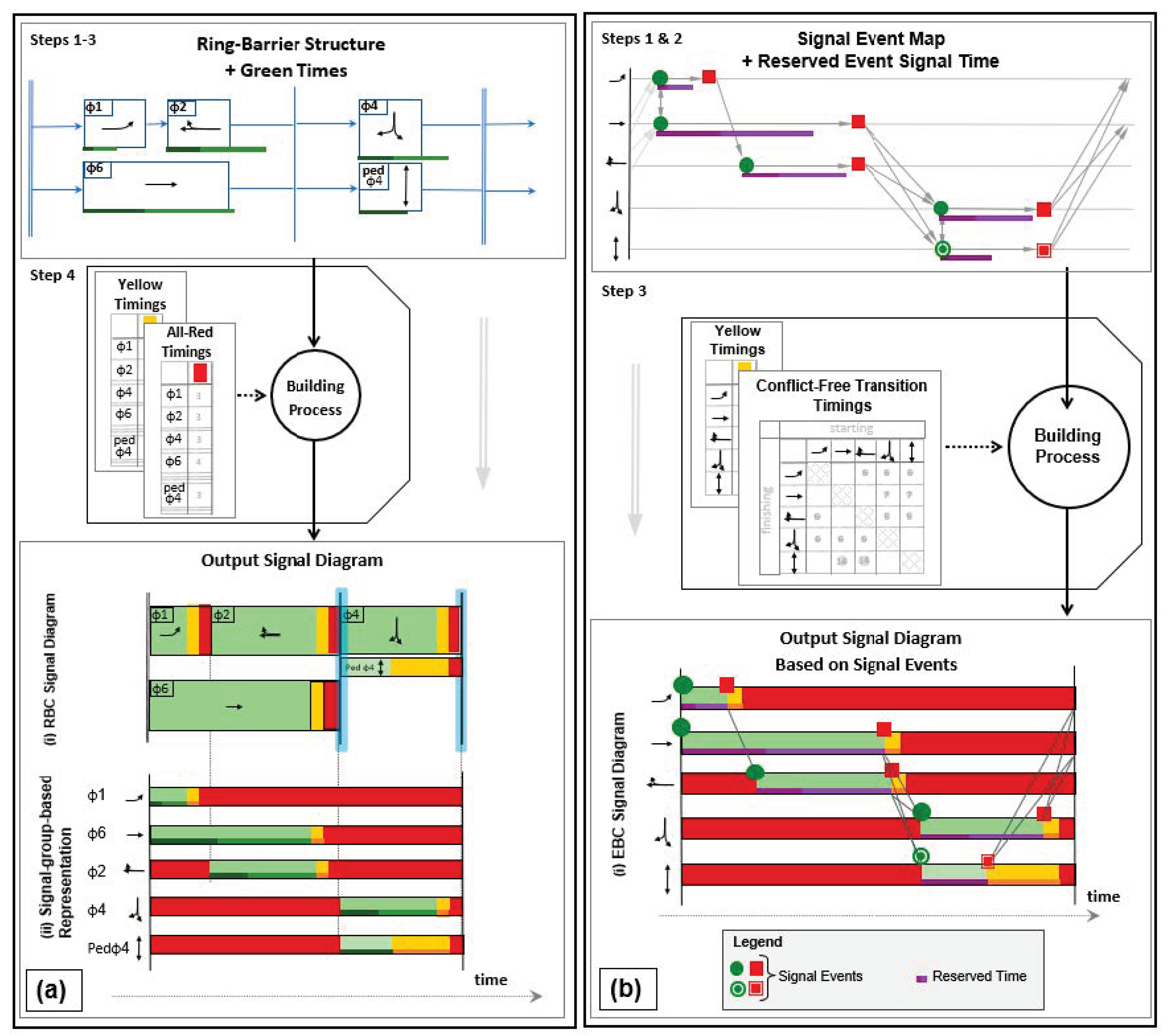
- A ring-barrier structure is defined to propose precedence relations between different movements based on potential conflicts.
- Phase green times are defined (such as minimum green, maximum green, etc.).
- Constant duration intervals (such as yellow change and red clearance) for each phase are defined.
- Master clock settings are defined, in the case of coordinated operations (configuring coordination timing settings such as offsets and splits).
- Define a signal event map comprising precedence relations between signal events. Each signal event specifies the activation of a particular traffic signal for the designated signal group (depicted as green circles or red squares in Figure 3b-i).
- Specify signal event reserved times—the time duration after activating a signal event reserved exclusively for that event—preventing the switch to other signals (represented by the purple line in Figure 3b-i).
- Determine constant time intervals, such as yellow-change timings, and intervals within the “intergreen matrix” based on conflicting movements. It should be noted that the constant intervals between the conflicting movements are another flexibility of the EBC over traditional NEMA-based controllers (RBC). For instance, the EBC can alter yellow timings after one phase depending on what phase will start after that.
- Establish coordination timing settings, including the synchronization time point for a signal event (synchronization time point indicates the specific moment in the cycle when the signal events are synchronized to start). In this context, the signal event should be activated precisely at that designated point (similar to offset in RBC with some additional capabilities such as achieving the synchronization point by adjusting the reserved time).
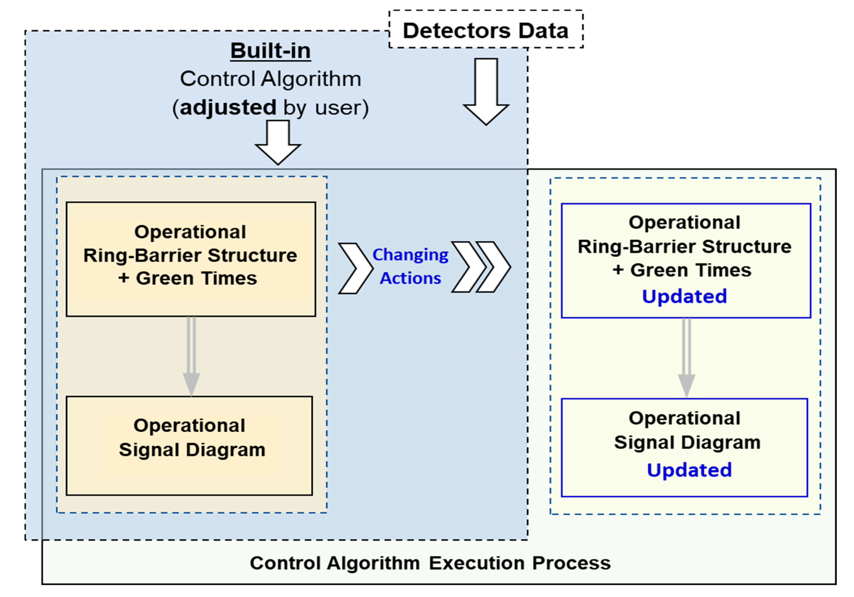
- Develop the foundational fixed-time control, as mentioned earlier.
- Activate and fine-tune the built-in algorithm capable of adjusting basic operational timings through common “changing actions”, including
- Modifying green interval durations (e.g., shortening/lengthening).
- Omitting phases.
- Predefined algorithms are integrated into the system.
- Changing actions are not directly accessible to a signal professional.
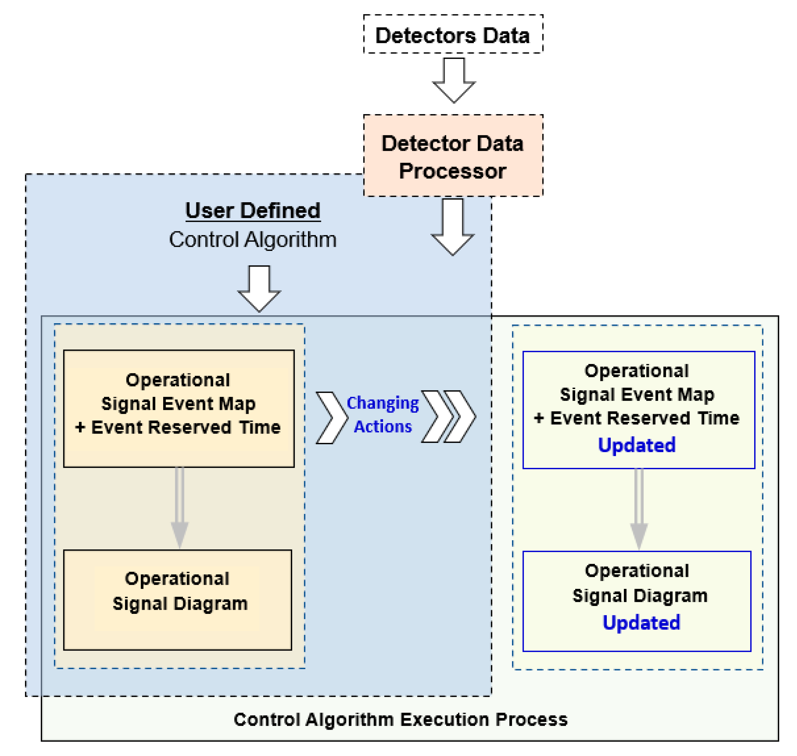
- Condition blocks that determine “when to change” the signal diagram by adjusting the corresponding signal event map.
- Execution blocks that decide “what to change”—specifying the modifications to be applied to the operational signal diagram.
- RBC is restricted to a barrier, which requires the signal professional to go beyond the traditional features of the controller to develop flexible logic based on the desired conditions.
- RBC’s functionalities are restricted to the built-in algorithms, and signal professionals are required to only input parameters but cannot change the predefined algorithm.
- Expressiveness: The degree to which a programming language allows a programmer to communicate their intentions and logic clearly and efficiently.
- Simplicity: The ease with which a programmer can comprehend and utilize the fundamental concepts and principles of a programming language.
- Brevity: The quality of conciseness of code written in a programming language.
3.2. EBC Overall Programming Workflow
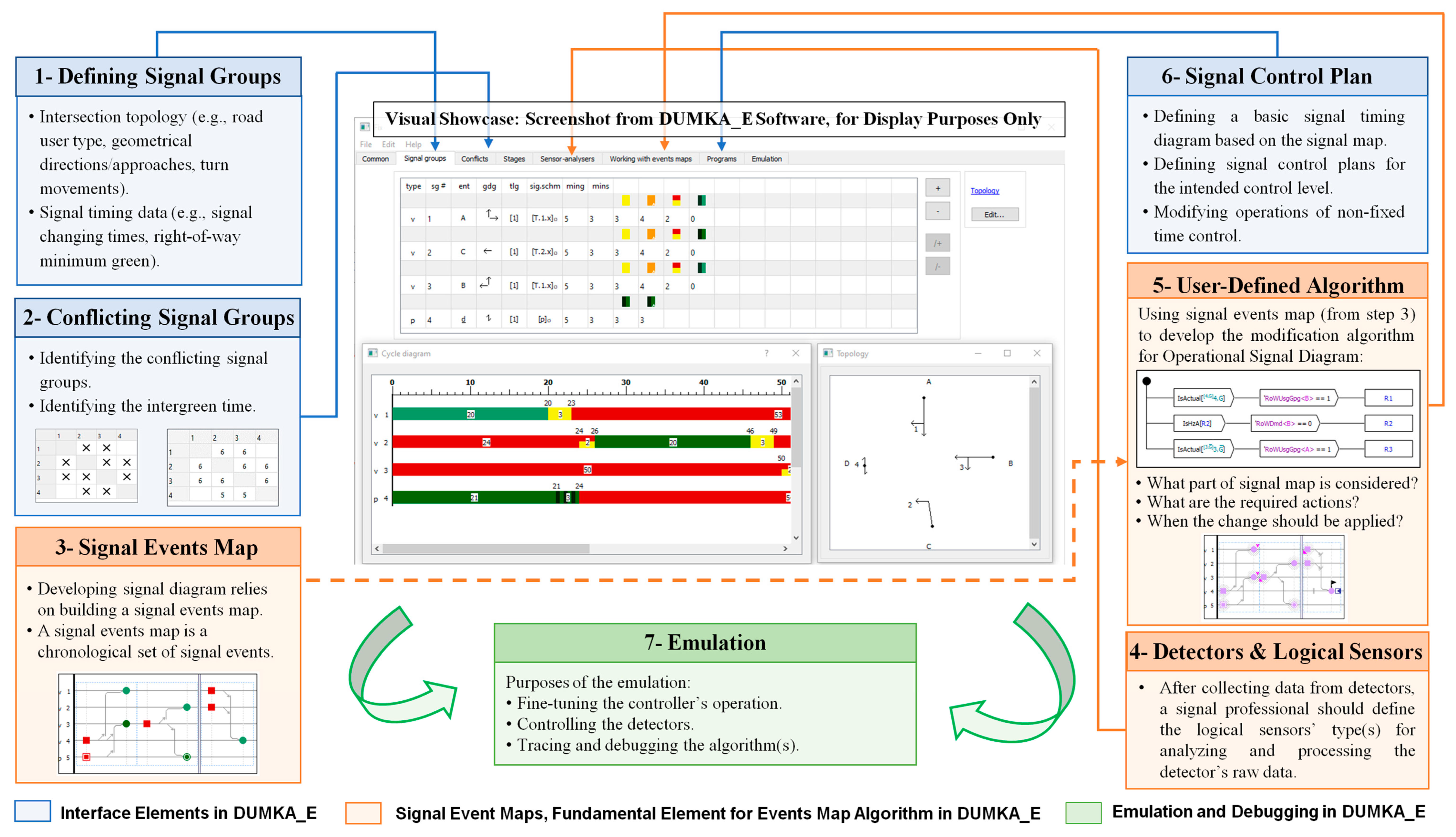
- Step 1:
- Defining Signal Groups: To establish well-defined signal groups, it is necessary to provide qualitative data (e.g., road user type, geometrical directions/approaches, etc.) and quantitative data (e.g., signal phase changing times, minimum greens, etc.).
- Step 2:
- Defining Conflicting Signal Groups: To prevent potential conflicts, it is crucial to meticulously define signal groups with conflicting rights of way. Additionally, careful consideration should be given to the intergreen times, the duration between the end of the right-of-way for one signal group, and the commencement of the right-of-way for the conflicting group.
- Step 3:
- Defining Signal Events Map: Constructing a signal events map hinges on the creation of a map detailing every signal event. This map is a chronological compilation of signal events linked by precedence relations based on their occurrences in a timely manner.
- Step 4:
- Defining Detector Data Processor (if needed): Defining the detector data processor (logical sensor) is a step that involves the postprocessing of detection data and the preprocessing of controller data. This step takes place only if there are physical detectors installed in the field. It interprets detectors’ values and prepares them for use as high-level data in the controller logic, such as the two examples: (i) the right-of-way demand analyzer or (ii) the right-of-way gap analyzer explained below.
- “Right-of-Way-Demand-Detector”: This detector data processor outputs zero if, at the moment, there are no unserved road users in the detection zone; otherwise, it outputs 1.
- “Right-of-Way-Usage-Gap-Out-Detector”: This detector data processor reports a 0 if, during the green phase, there is no gap exceeding the given threshold value for traffic related to the specified signal group; otherwise, it outputs 1.
- Step 5:
- Defining User-Defined Algorithm: This section offers a set of actions to modify the specified operational signal diagram and to implement a desired algorithm. Based on the signal events map and the desired algorithm, the following information should be specified:
- The part of the signal event map that is under consideration for flexible changes (e.g., phase 1 gaps out, and the unused green time is transferred to phase 2).
- The actions that are intended to be applied (e.g., early green, red truncation, etc.)
- The moment when the changes should be applied to the signal event map.
- Step 6:
- Defining Signal Control Plan: Defining the signal control plan is another important section of the process in EBC DUMKA_E. It provides the signal professional an opportunity to determine a basic signal timing diagram based on the signal map. Additionally, in the case of a non-fixed-time control, it is possible to make further operational modifications (e.g., adaptive behavior algorithms).
- Step 7:
- Emulating the Controller’s Performance: EBC DUMKA_E can emulate any of the developed control logics. The emulation is helpful for the following purposes: fine-tuning operations of the controller, observing detection status, and tracing and debugging the algorithm (if needed) before implementing it.
- (1)
- When to change the parameters.
- (2)
- How to change the corresponding parameters on the signal event map.
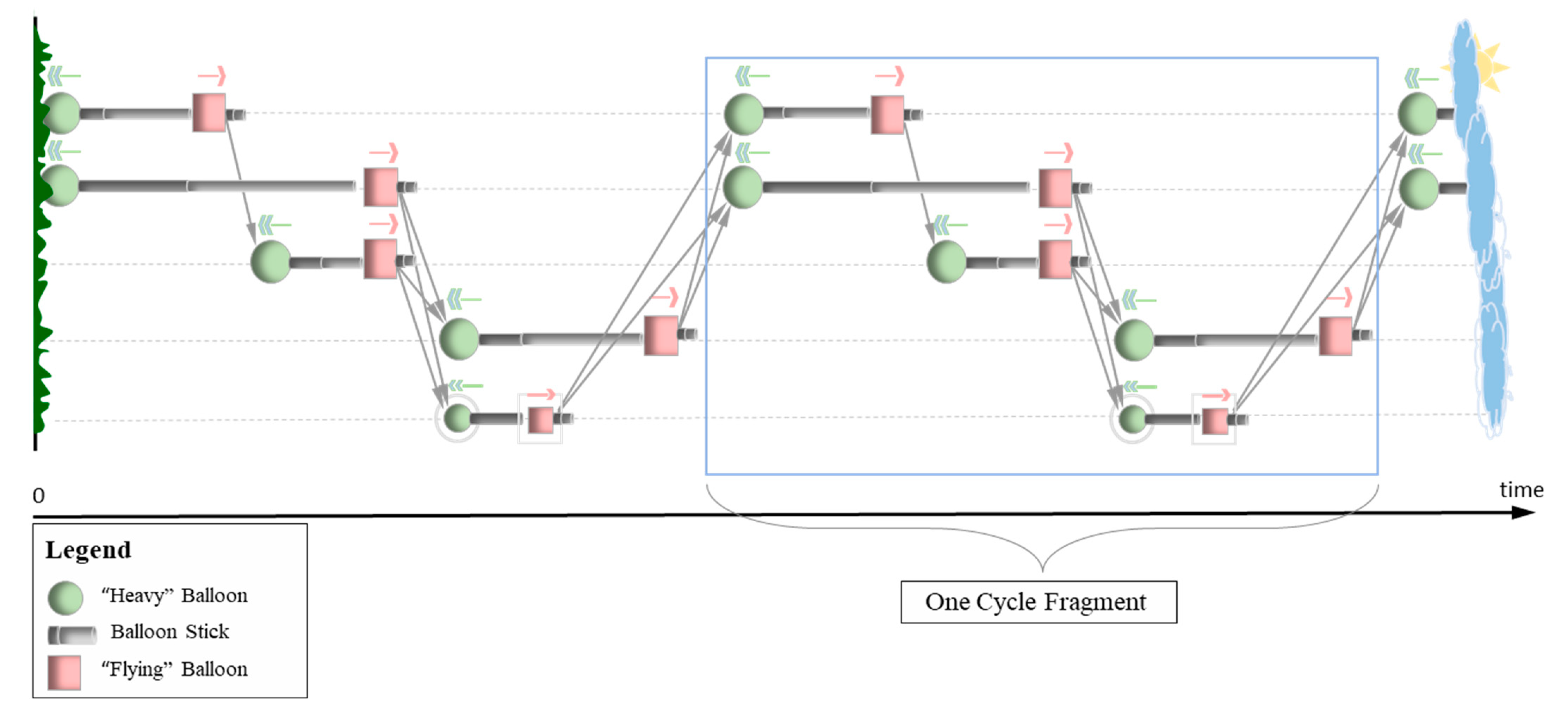
3.3. EBC Building Process, Methodology and Concept
- A green round balloon, heavier than air, tends to descend towards the ground.
- A pink square balloon, designed to be lighter than air (e.g., filled with helium), tends to ascend upwards (flying).
- A vertical stick, composed of two segments, with the lower end affixed to the balloon.
- Imaginary directed connections between these elements enforce specific spatial constraints.
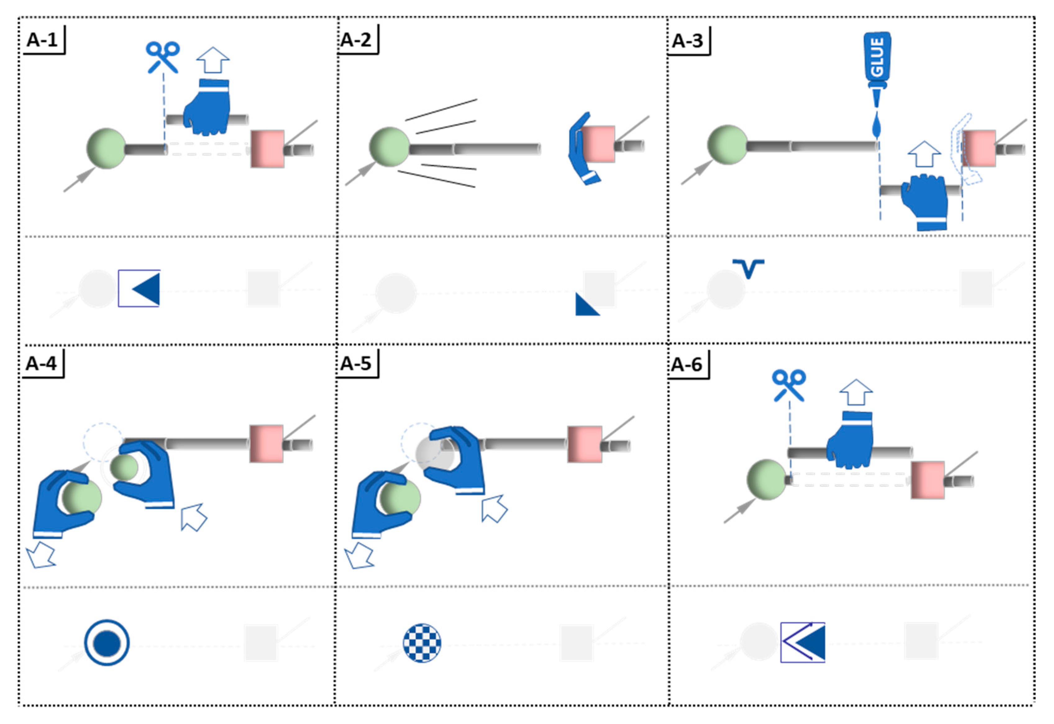
- A-1
- Shorten the balloon stick to its minimum length.
- A-2
- Manually stabilize a balloon to prevent it from descending during transitions between equilibrium states.
- A-3
- Lengthen a balloon stick to its maximum length without disrupting the equilibrium state.
- A-4
- Alter the size of the balloon and/or switch the balloon type from “heavy” to “flying” and vice versa.
- A-5
- Change the balloon to transparent (invisible).
- A-6
- Minimize the balloon stick to its utmost minimum value.
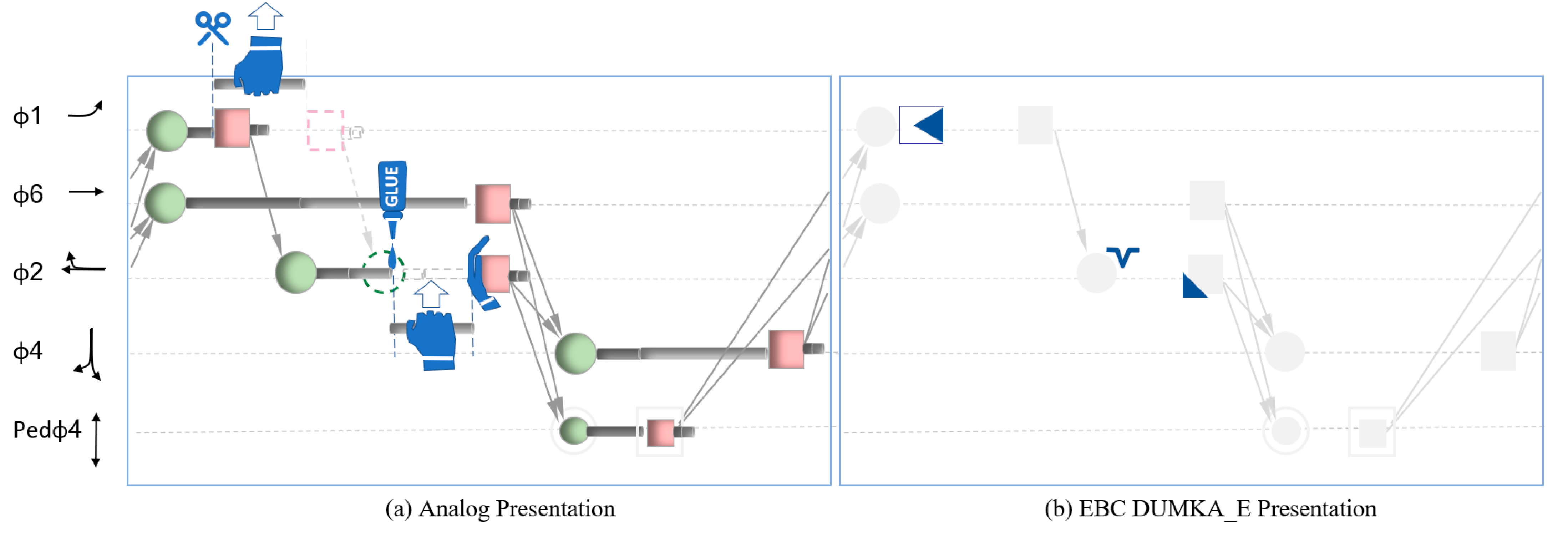
- Modification 1:
- Shortening the green time for one signal group to its minimum value and reallocating the unused time to the green time of another signal group, thereby maintaining the cycle length.
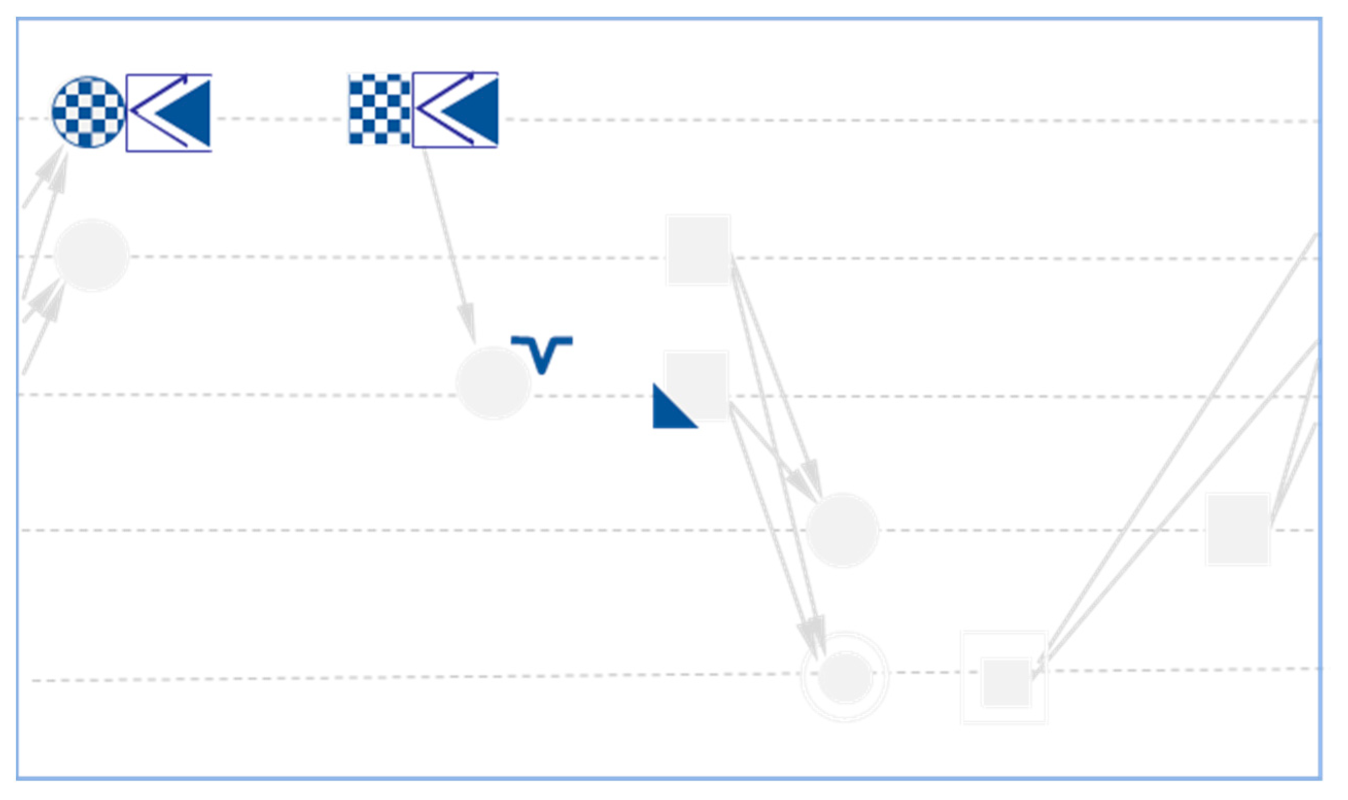
- Modification 2:
- Skipping the green activation for one signal group and reallocating the unused time to the green time of another signal group, thereby maintaining the cycle length.
- Define “when to change” as an if-then flowchart (Figure 11).
4. Experimental Set-Up
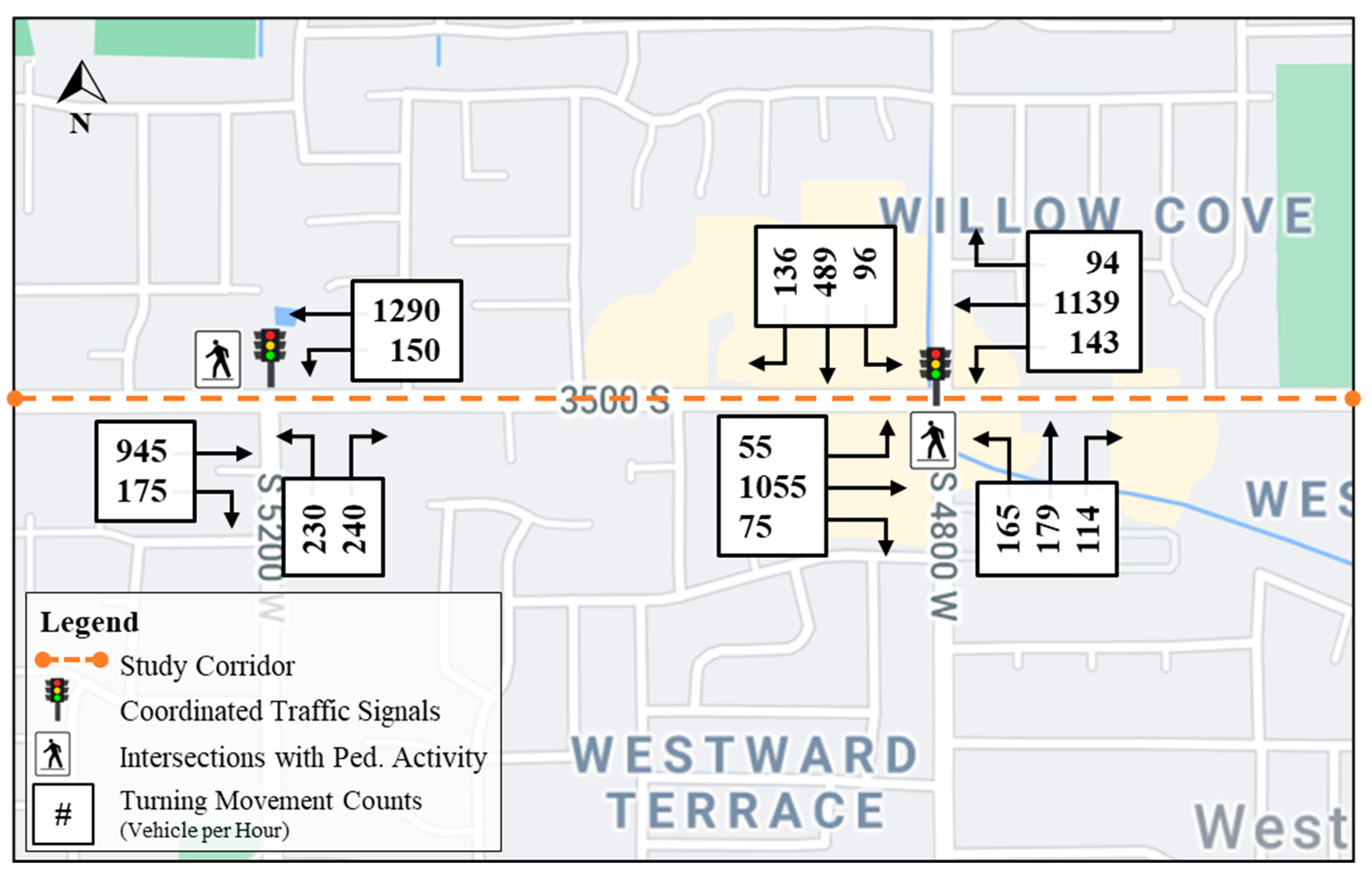
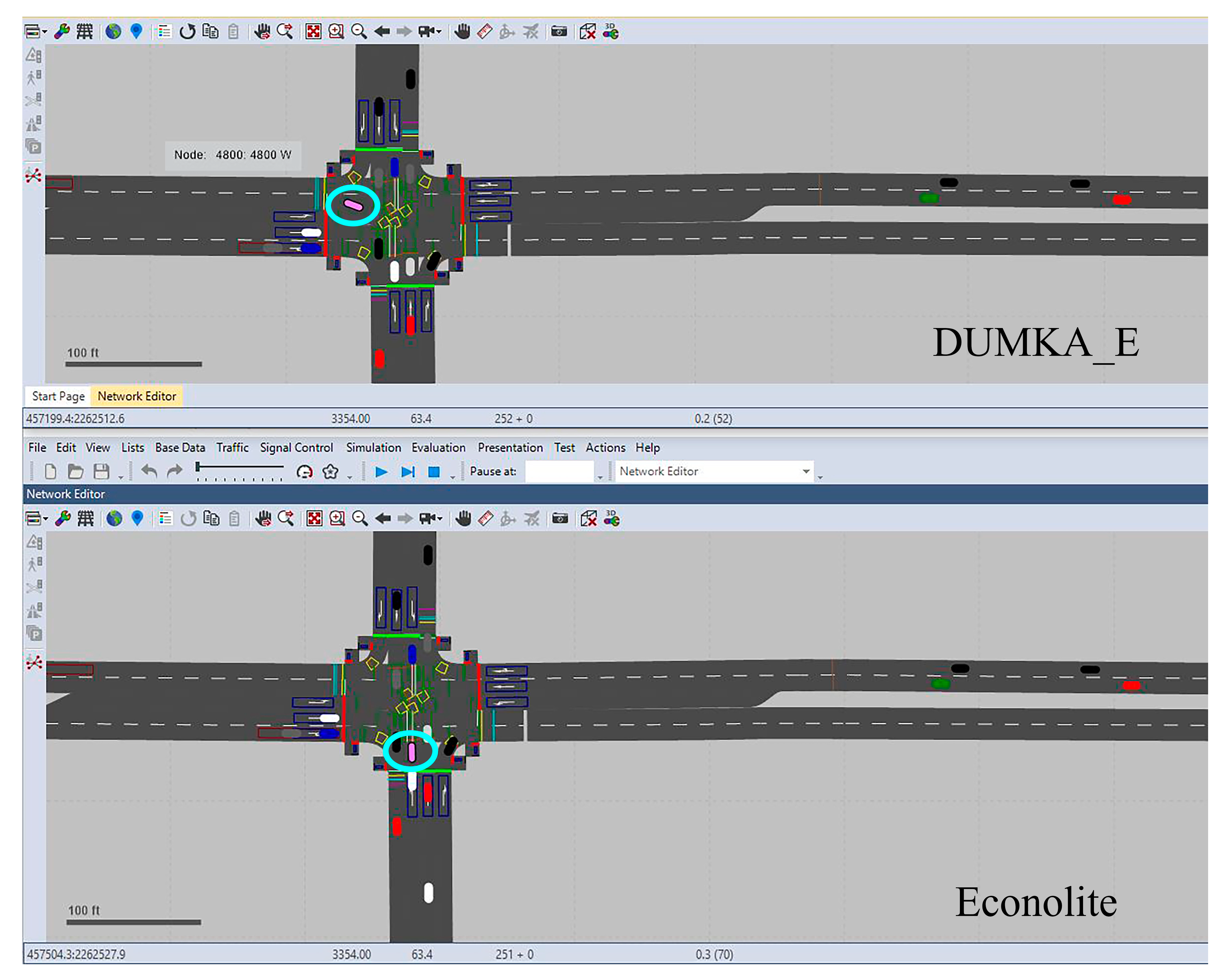
4.1. Simulation Testbed
4.2. Experimental Design
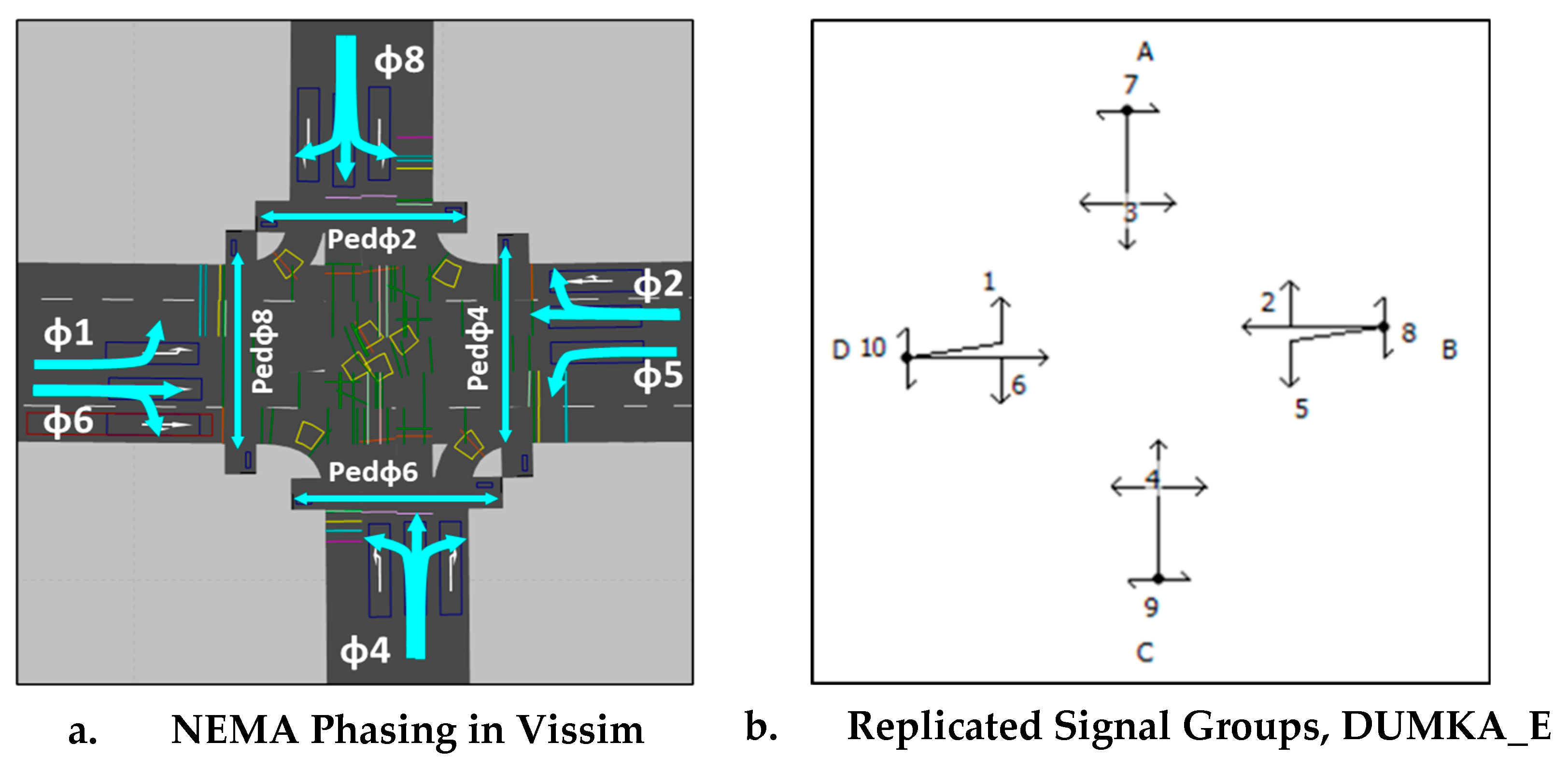
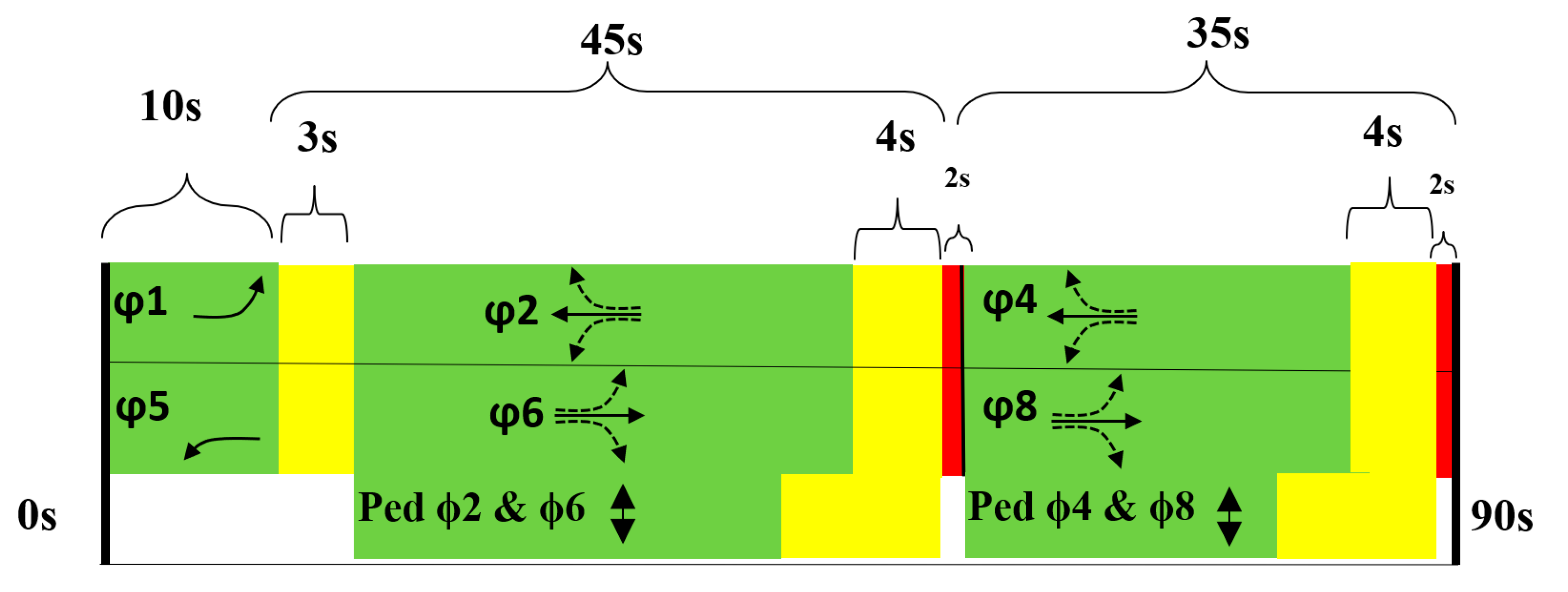
4.2.1. Replicating RBC Operations through EBC/DUMKA_E
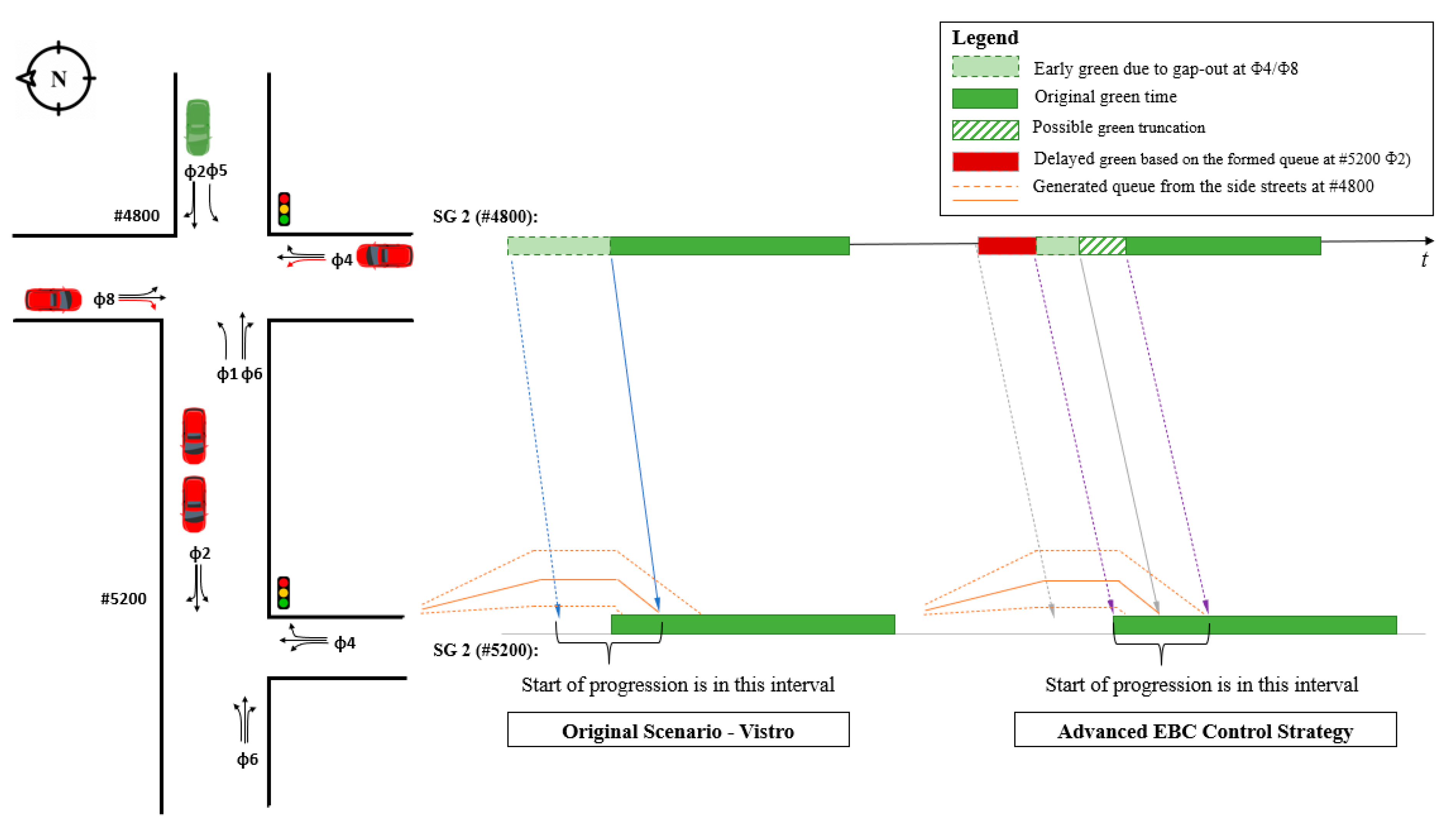
4.2.2. Advanced EBC Control Strategy for Coordinated Phase Initialization
5. Results and Discussion
5.1. Replicating RBC Operations through EBC DUMKA_E
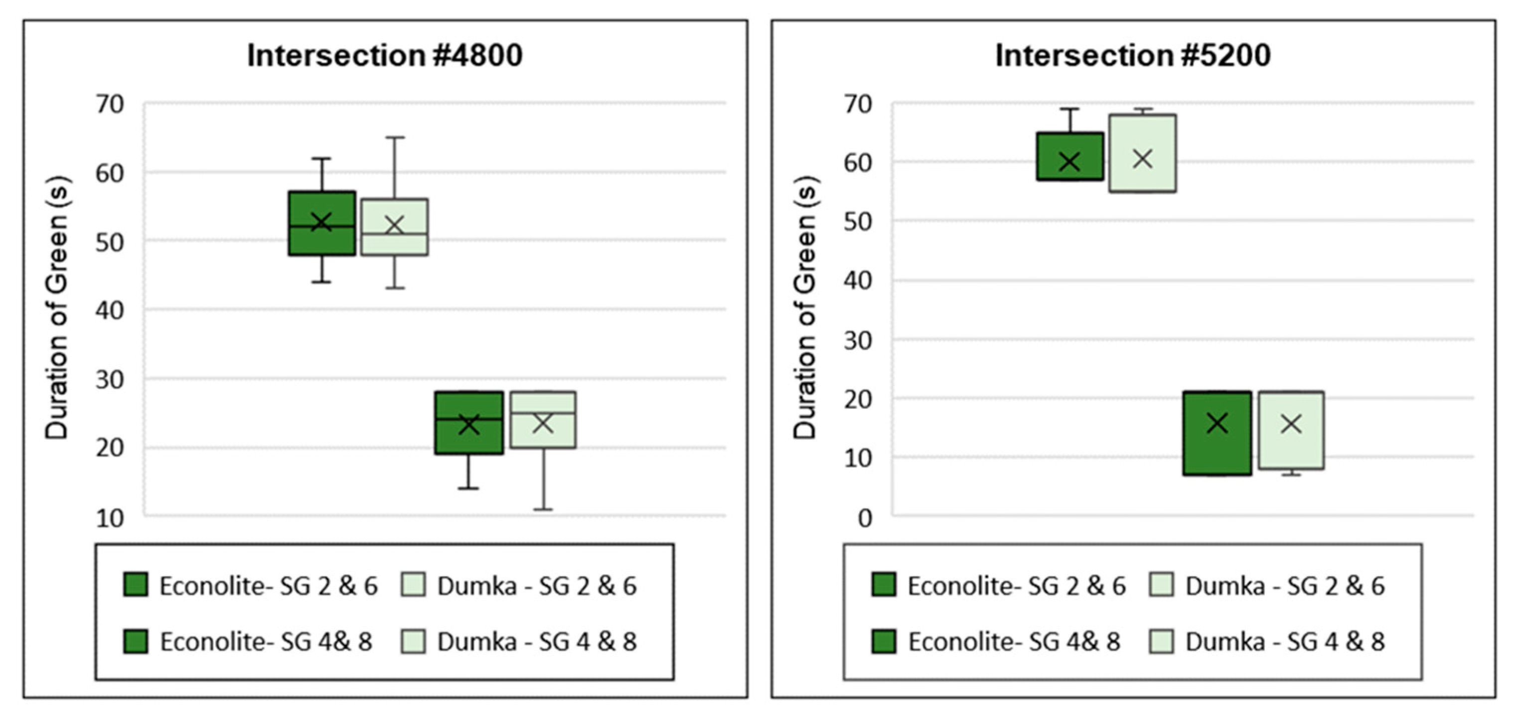
5.1.1. Duration of Green
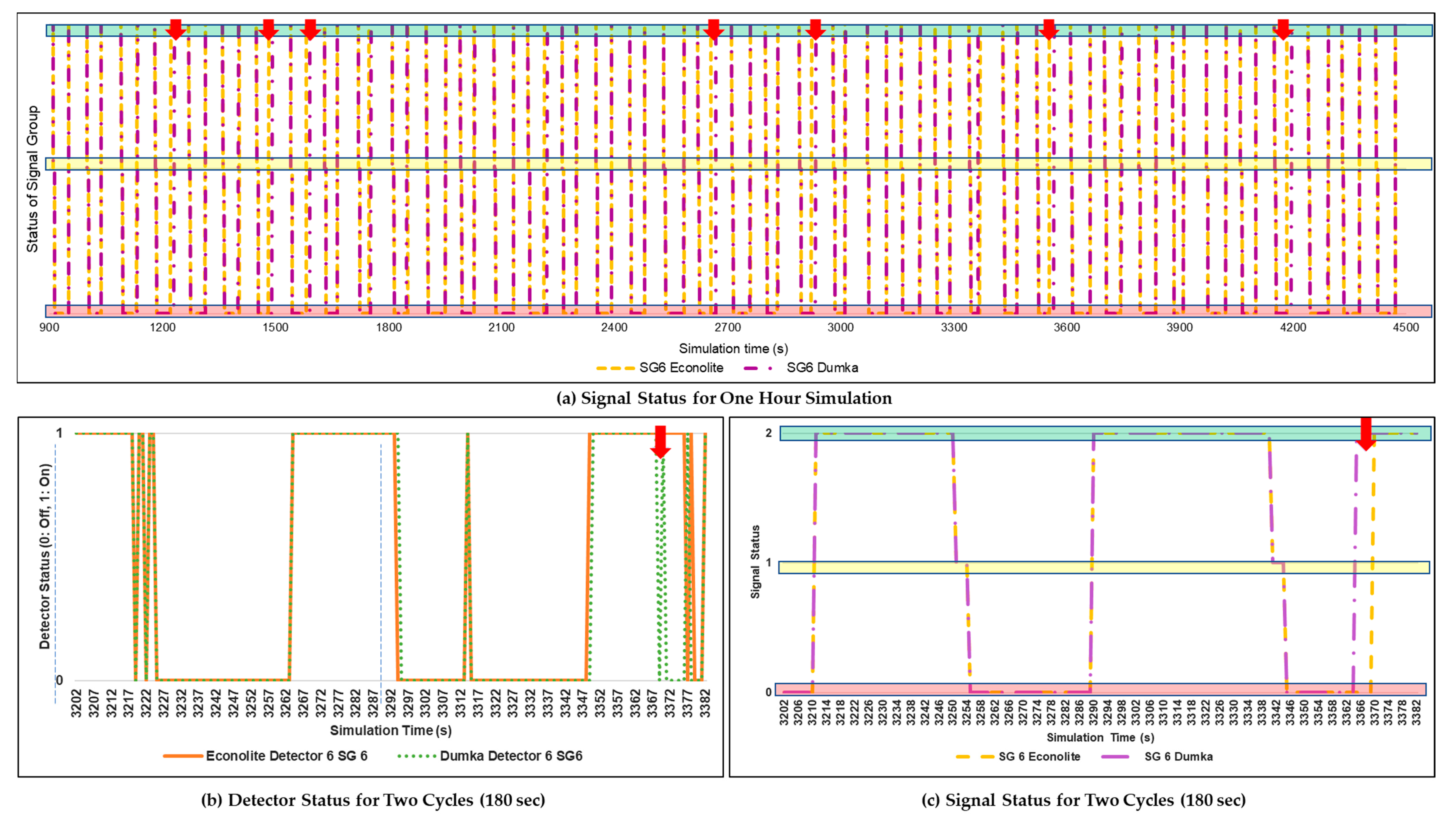
5.1.2. Detection Inconsistency
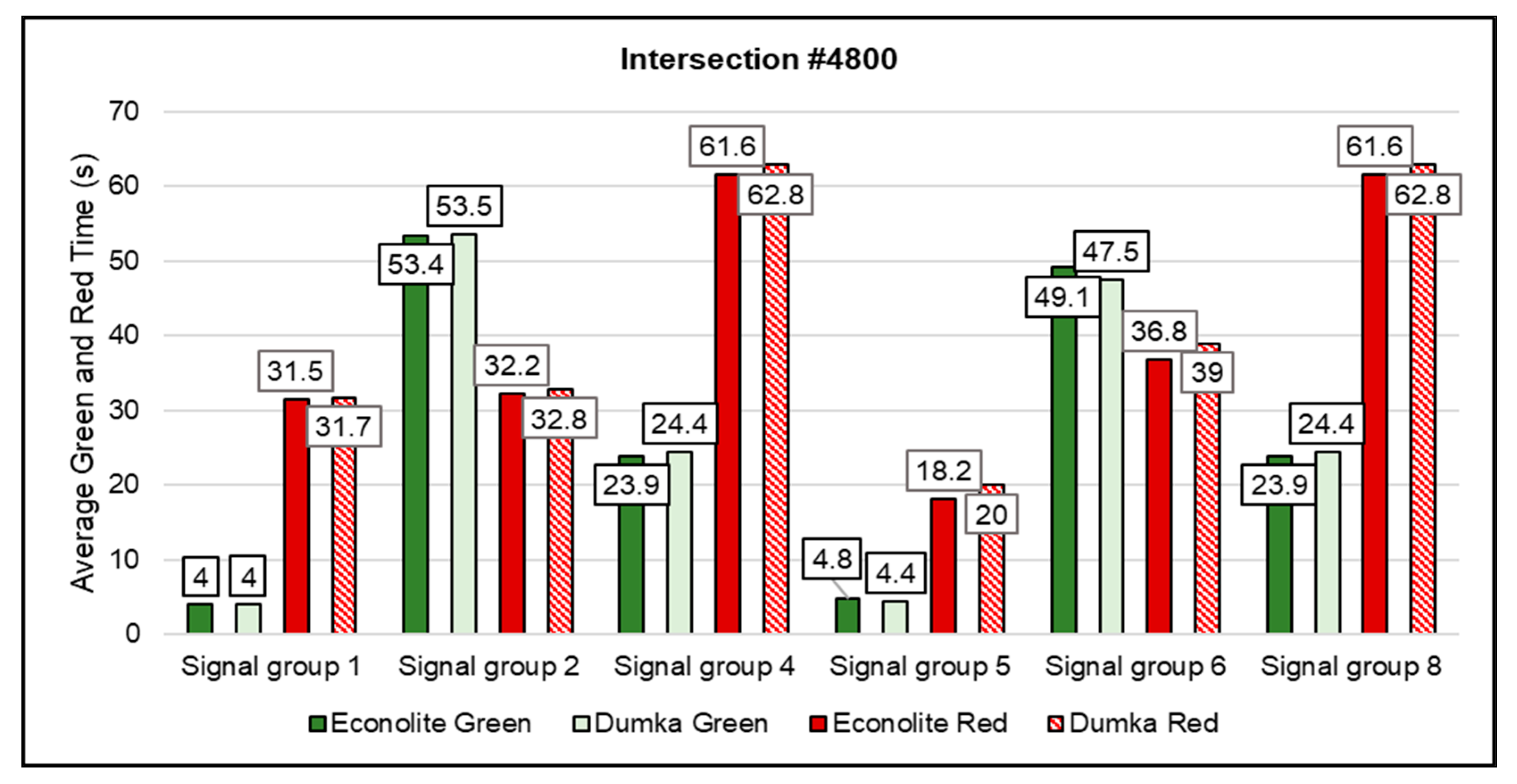
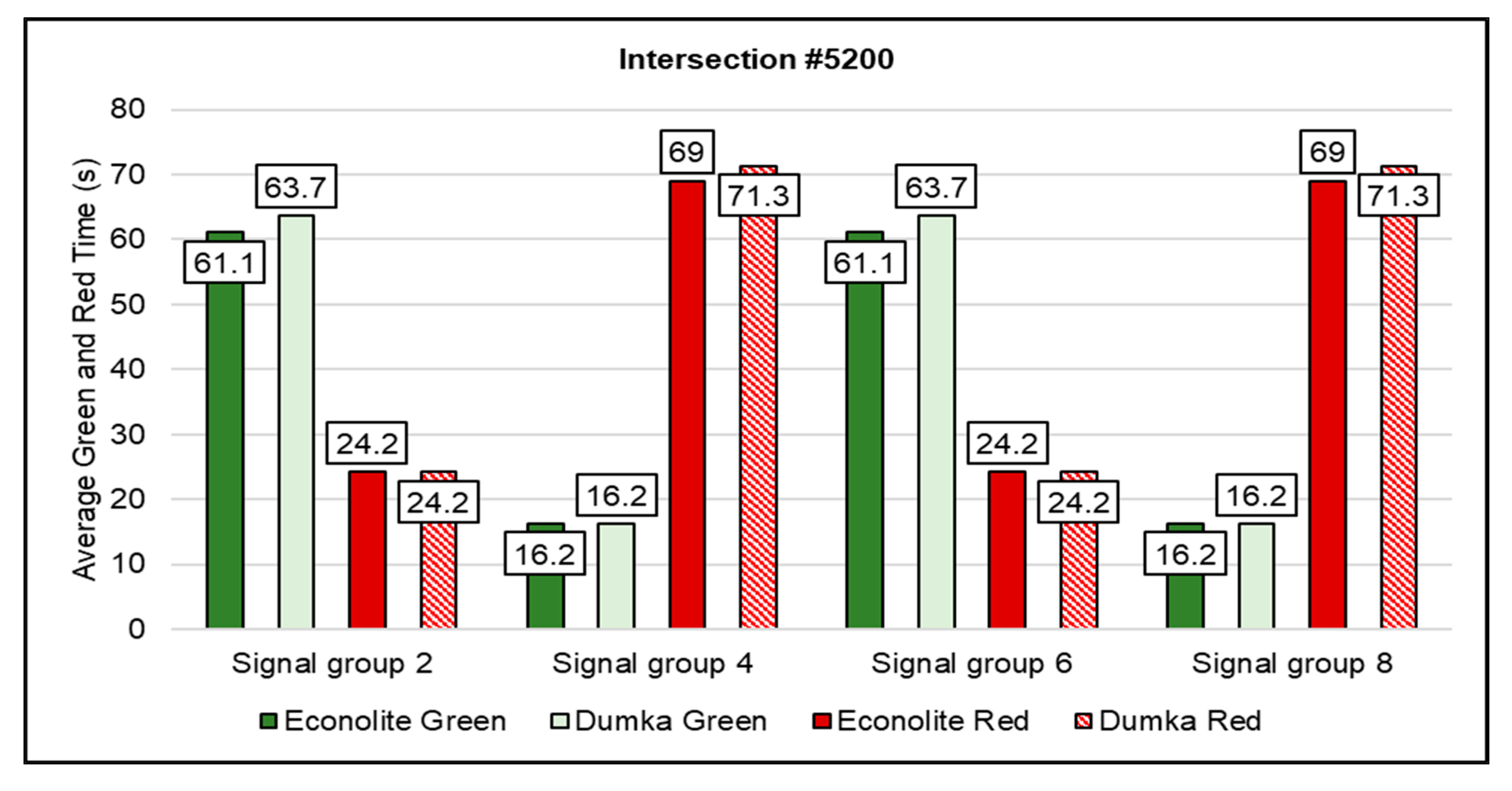
5.1.3. Average Green and Red Time
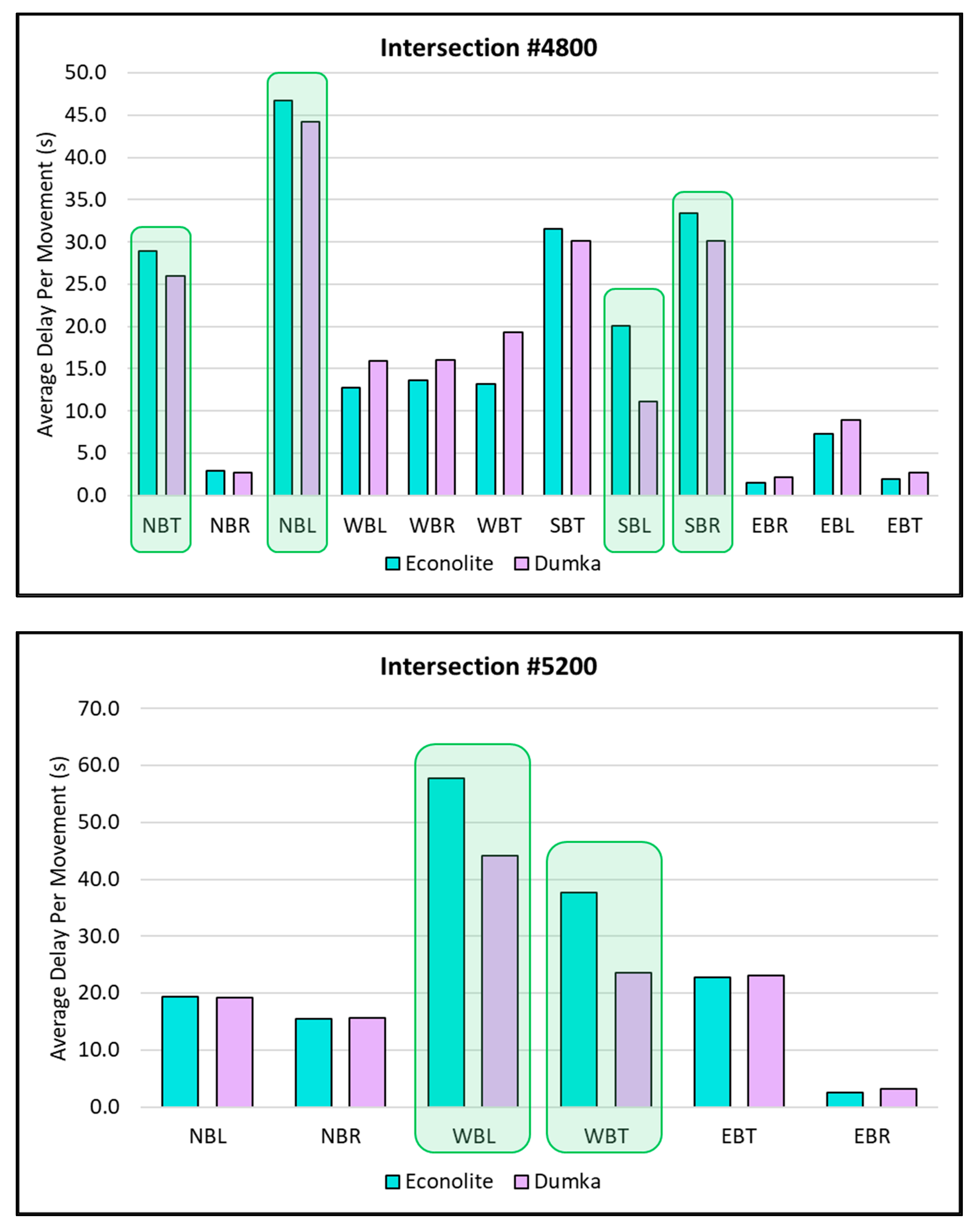
5.2. Advanced EBC Control Strategy for Coordinated Phase Initialization
Average Delay per Movement
6. Conclusions
Author Contributions
Funding
Data Availability Statement
Conflicts of Interest
References
- Retting, R.A.; Chapline, J.F.; Williams, A.F. Changes in crash risk following re-timing of traffic signal change intervals. Acid. Anal. Prev. 2002, 34, 215–220. [Google Scholar] [CrossRef] [PubMed]
- Zegeye, S.K.; De Schutter, B.; Hell, H. Reduction of travel times and traffic emissions using model predictive control. In Proceedings of the American Control Conference, St. Louis, MO, USA, 10–12 June 2009. [Google Scholar]
- Koonce, P.; Rodegerdts, L. Traffic Signal Timing Manual; FHWA-HOP-08-024; Federal Highway Administration: Washington, DC, USA, 2008. [Google Scholar]
- Lin, S.; De Schutter, B.; Xi, Y.; Hellend, H. Integrated Urban Traffic Control for the Reduction of Travel Delays and Emissions. IEEE Trans. Intell. Transp. Syst. 2013, 14, 1609–1619. [Google Scholar] [CrossRef]
- World Health Organization. Global Status Report on Road Safety 2018; World Health Organization: Geneva, Switzerland, 2019. [Google Scholar]
- Park, B.; Yun, I.; Ahn, K. Stochastic Optimization for Sustainable Traffic Signal Control. Int. J. Sustain. Transp. 2009, 3, 263–284. [Google Scholar] [CrossRef]
- Urbanik, T.; Beaird, S.; Gettman, D.; Head, L.; Bullock, D.; Smaglik, E.; Campbell, R.; Ablett, M. Traffic Signal State Transition Logic Using Enhanced Sensor Information; National Cooperative Highway Research Program Transportation Research Board: Washington, DC, USA, 2003. [Google Scholar]
- He, Q.; Head, K.L.; Ding, J. Multi-modal traffic signal control with priority, signal actuation and coordination. Transp. Res. Part C 2014, 46, 65–82. [Google Scholar] [CrossRef]
- Luker, M.; Signal Controller Peer-to-Peer Communications. 16 January 2016. Available online: https://docs.lib.purdue.edu/atspmw/2016/Presentations/9/ (accessed on 22 November 2023).
- Johnson, J. ASC/3 Logic Processor Programming. Econolite, Reference: AN2068, 2007. Available online: http://www.signalcontrol.com/tech_papers/econolite/AN2068%20ASC3%20Logic%20Processor%20Programming.pdf (accessed on 28 November 2023).
- PTV AG. PTV Vissim 2022 User Manual; PTV Group: Karlsruhe, Germany, 2022. [Google Scholar]
- Econolite Control Products, Inc. Advanced System Controllers ASC/3 Programming Manual; Econolite: Anaheim, CA, USA, 2007. [Google Scholar]
- Electrical and ITS Engineering. Programming Guide Econolite Cobalt Controller; British Columbia Ministry of Transportation and Infrastructure: Coquitlam, BC, Canada, 2019. [Google Scholar]
- PTV Group. Ring Barrier Controller (RBC) User Manual Vissim; PTV Group: Karlsruhe, Germany, 2014. [Google Scholar]
- Wang, Q. Street Traffic Signal Optimal Control for NEMA Controllers. Doctoral Dissertation, Virginia Polytechnic Institute and State University, Blacksburgh, VA, USA, 2019. [Google Scholar]
- Zlatkovic, M.; Stevanovic, A.; Martin, P.; Tasic, I. Evaluation of Transit Signal Priority Options for Future Bus Rapid Transit Line in West Valley City, Utah. Transp. Res. Rec. 2012, 2311, 176–185. [Google Scholar] [CrossRef]
- Zlatkovic, M.; Stevanovic, A.; Martin, P.T. Development and Evaluation of Algorithm for Resolution of Conflicting Transit Signal Priority Requests. Transp. Res. Rec. 2012, 2311, 167–175. [Google Scholar] [CrossRef]
- Zlatkovic, M.; Stevanovic, A.; Zhou, X.; Tasic, I.; Ostojic, M. 400 South Corridor Assessment; Mountain-Plains Region; University Transportation Center sponsored by the U.S. Department of Transportation: Washington, DC, USA, 2017.
- Zlatkovic, M.; Martin, P.T.; Stevanovic, A. Predictive Priority for Light Rail Transit. Transp. Res. Rec. J. Transp. Res. Board 2011, 2259, 168–178. [Google Scholar] [CrossRef]
- Furth, P.G.; Koonce, P.J.; Miao, Y.; Peng, F. Mitigating Right-Turn Conflict with Protected Yet Concurrent Phasing for Cycle Track and Pedestrian Crossings. Transp. Res. Rec. 2014, 2438, 81–88. [Google Scholar] [CrossRef]
- Furth, P.G.; Razavi, S. Leading Through Intervals versus Leading Pedestrian Intervals: More Protection with Less Capacity Impact. Transp. Res. Rec. 2019, 2673, 152–164. [Google Scholar] [CrossRef]
- Wang, A.; Tian, Z. Leveraging Fully Actuated Signal Coordination and Phase Reservice to Facilitate Signal Timing Practices. Transp. Res. Rec. 2022, 2677, 240–251. [Google Scholar] [CrossRef]
- Furth, P.; Muller, T.H.; Salomons, M.; Bertulis, T.; Koonce, P.J. Barrier-Free Ring Structures and Pedestrian Overlaps in Signalized Intersection Control. Transp. Res. Rec. 2012, 2311, 132–141. [Google Scholar] [CrossRef]
- Zlatkovic, M.; Kergaye, C. Development of crash modification factors for continuous flow intersections. J. Road Traffic Eng. 2018, 64, 5–11. [Google Scholar] [CrossRef]
- Gavric, S.; Sarazhinsky, D.; Stevanovic, A.; Dobrota, N. Development and Evaluation of Non-traditional Pedestrian Timing Treatments for Coordinated Signalized Intersections. Transp. Res. Rec. 2022, 2677, 460–474. [Google Scholar] [CrossRef]
- Pappis, C.P.; Mamdani, E.H. A Fuzzy Logic Controller for a Trafc Junction. IEEE Trans. Syst. Man, Cybern. 1977, 7, 707–717. [Google Scholar] [CrossRef]
- Nakatsuyama, H.; Nishizuka, N.N. Fuzzy Logic Phase Controller for Traffic Junctions in the One-way Arterial Road. IFAC Proc. Vol. 1984, 17, 2865–2870. [Google Scholar] [CrossRef]
- Chiu, S. Adaptive traffic signal control using fuzzy logic. In Proceedings of the Intelligent Vehicles ‘92 Symposium, Detroit, MI, USA, 29 June–1 July 1992. [Google Scholar]
- Beauchamp-Baez, G.; Rodriguez-Morales, E. A Fuzzy Logic Based Phase Controller for Traffic Control. In Proceedings of the 6th International Fuzzy Systems Conference, Barcelona, Spain, 5 July 1997. [Google Scholar]
- Niittymaki, J.; Kikuchi, S. Application of Fuzzy Logic to the Control of a Pedestrian Crossing Signal. Transp. Res. Rec. 1998, 1651, 30–38. [Google Scholar] [CrossRef]
- Murat, Y.S.; Cakici, Z.; Yaslan, G. Use of Fuzzy Logic Traffic Signal Control Approach as Dual Lane Ramp Metering Model for Freeways. In Soft Computing in Industrial Applications; Springer: Cham, Switzerland, 2014. [Google Scholar]
- Mulandi, J.; Stevanovic, A.; Martin, P.T. Cross-evaluation of signal timing optimized by various traffic simulation and signal optimization tools. Transp. Res. Rec. 2010, 2192, 147–155. [Google Scholar] [CrossRef]


| Flexibility to: | Stage-Based Traffic Control | Signal Group-Based Traffic Control | ||
|---|---|---|---|---|
| Ring-and-Barrier Control (NEMA) | Interval-Based Control | Event-Based Control | ||
| 1–Define Pretimed (Cyclic) Signal Diagram |  |  |  | |
| Highly limited to comply with stage-interstage structure. | * Limited to comply with ring-barrier structure | |||
| 2–Modify the Pretimed (Cyclic) Signal Diagram While Operating | | | | |
| Highly limited–Signal groups are constrained by stages and interstages. | * Limited–Phases are needed to comply with the ring-barrier structure. | * Limited to modify only some part of signal intervals (e.g., early start) | ||
| 3–Define the Algorithm for Modifying the Pretimed (Cyclic) Signal Diagram | | | | |
| Algorithm presented in the form of flow charts consists of stages and interstages. | Limited to predefined/built-in algorithms only. | Limited to predefined/built-in algorithms only. | ||
Disclaimer/Publisher’s Note: The statements, opinions and data contained in all publications are solely those of the individual author(s) and contributor(s) and not of MDPI and/or the editor(s). MDPI and/or the editor(s) disclaim responsibility for any injury to people or property resulting from any ideas, methods, instructions or products referred to in the content. |
© 2024 by the authors. Licensee MDPI, Basel, Switzerland. This article is an open access article distributed under the terms and conditions of the Creative Commons Attribution (CC BY) license (https://creativecommons.org/licenses/by/4.0/).
Share and Cite
Ardalan, T.; Sarazhinsky, D.; Dobrota, N.; Gavric, S.; Stevanovic, A. Overview and Modeling Capabilities of an Event-Based Signal Controller. Symmetry 2024, 16, 157. https://doi.org/10.3390/sym16020157
Ardalan T, Sarazhinsky D, Dobrota N, Gavric S, Stevanovic A. Overview and Modeling Capabilities of an Event-Based Signal Controller. Symmetry. 2024; 16(2):157. https://doi.org/10.3390/sym16020157
Chicago/Turabian StyleArdalan, Taraneh, Denis Sarazhinsky, Nemanja Dobrota, Slavica Gavric, and Aleksandar Stevanovic. 2024. "Overview and Modeling Capabilities of an Event-Based Signal Controller" Symmetry 16, no. 2: 157. https://doi.org/10.3390/sym16020157
APA StyleArdalan, T., Sarazhinsky, D., Dobrota, N., Gavric, S., & Stevanovic, A. (2024). Overview and Modeling Capabilities of an Event-Based Signal Controller. Symmetry, 16(2), 157. https://doi.org/10.3390/sym16020157