Article

Modeling of Satellite-to-Underwater Integrated FSO-PON System Using NOMA-VLC

by
Vivek Arya
1,*,
Meet Kumari
2,
Hamza Mohammed Ridha Al-Khafaji
3,* and
Syed Alwee Aljunid
4
1
Department of Electronics and Communication Engineering, FET, Gurukula Kangri (Deemed to be University), Haridwar 249404, Uttarakhand, India
2
Department of Electronics and Communication Engineering, Chandigarh University, Mohali 140413, Punjab, India
3
Biomedical Engineering Department, Al-Mustaqbal University College, Hillah 51001, Babil, Iraq
4
Faculty of Electronic Engineering Technology, Universiti Malaysia Perlis, Arau 02600, Perlis, Malaysia
*
Authors to whom correspondence should be addressed.
Symmetry 2023, 15(3), 739; https://doi.org/10.3390/sym15030739
Submission received: 4 February 2023 / Revised: 3 March 2023 / Accepted: 13 March 2023 / Published: 16 March 2023
(This article belongs to the Section Physics)

Abstract

:
In recent years, optical wireless communication has promised several benefits over radio frequency communication in atmospheric, deep space and underwater communications. Satellite-to-underwater communication technology can be applied to commercial, naval, scientific and engineering operations because of its high data rate, high security, long-reach and low cost. In this paper, a high-speed, long-reach integrated free space optics (FSO)-passive optical network (PON) system using non-orthogonal multiple access visible light communication (NOMA-VLC) is proposed. It poses a 10/2.5 Gbps per channel bit rate for satellite-to-underwater applications. Numerically calculated results provide the splitter power budget of −35 dBm in the downlink and −32 dBm in the uplink. Additionally, a receiver sensitivity of 23 dB in the downlink and 10 dB in the uplink direction can be obtained in the system using a modified new zero cross-correlation (MNZCC) code under clear environment conditions. Again, the simulative analyses indicate that the suggested system supports 290 underwater devices successfully and offers a high 10 dBm signal-to-noise ratio over 10 km FSO, 100 km fiber and 5 m VLC range. Moreover, it provides a signal-to-noise ratio of 39 dB, with −9 dBm received optical power at 300 fields of view under fiber-wireless channels’ impairments. We argue that the suggested system is a symmetric system adapted to different link distances and which offers improved receiver sensitivity and high received optical power at a 10−9 bit error rate (BER). The comparative analysis shows the advantages of the suggested system over previously reported works.

1. Introduction

With current advancements in fifth-generation (5G) networks, recent conventional networks are undergoing tremendous growth in the number of wireless consumers for several services in numerous scenarios, such as rural, urban and remote areas. As a solution to achieve a heterogeneous global network, satellite systems have been incorporated into underwater communications systems. Due to the increasingly large footprint, satellite-to-underwater communication offers wide and extensive wireless connectivity for several fixed as well as mobile users. Presently, it is extensively acknowledged that independent ongoing communication systems cannot cope with the growing traffic demands of several services. In this respect, a new configuration of satellite-to-underwater network has lately been realized [1,2].
Conversely, free space optics (FSO) communication has obtained huge consideration over the past twenty years. FSO have various benefits over existing microwave and radio frequency (RF) communication systems, such as huge bandwidth, unregulated spectrum, license-free operation, high transmission rate, long-reach transmission, re-usability with respect to wavelengths and equipment, exemption from electromagnetic interference (EMI) and high security. FSO are eminently suitable for numerous contexts, such as high-speed trains, unmanned aerial vehicles, indoor/outdoor local area networks (LANs), as well as wide area networks (WANs), building-to-building, deep-space and satellite communications. They sustain a higher transmission rate from Gbps to Tbps [3,4,5].
FSO underwater applications, called underwater optical wireless communication (UOWC), have been researched extensively. They transmit the data to industry, scientific and military communities. They are also involved in areas such as environmental monitoring, pollution monitoring, live video streaming, offshore exploration, maritime archaeology, port security, oil control and maintenance, imaging, oceanography, tactical surveillance and disaster precautions in UOWC. Due to their high transmission rate, short/long-range wireless links, low latency as well as less power consumption, UOWC has become an elegant substitute technology for conventional acoustic and RF in underwater communications [3]. Moreover, because of pioneering space technology and elaborated space-based instruments, FSO usher in a modern era of satellite communications. Taking into account practical atmosphere factors, the viability of an optical satellite-underwater link was proposed and verified [1].
Furthermore, by 2023, it is expected that there will be more than 13.1 billion wireless inter-connected devices, driving a remarkable growth in worldwide connectivity. The current RF spectrum is inadequate for managing such huge traffic. Visible light communication (VLC) ranging from 430 THz to 790 THz has developed as a potential candidate for 5G and even beyond 5G networks. VLC offers various advantages, such as ease of use, compact size, high durability, high power efficiency and no EMI radiation. In addition to this, it has a wide range of uses, such as light-fidelity (Li-Fi), healthcare, vehicular communication, door localization and underwater communication. Apart from these benefits, the VLC system is restricted in operation because of the light emitting diode (LED) bandwidth constraint operated in the MHz range. For this reason, various multiple-access technologies, such as code division multiple access (CDMA), orthogonal division multiple access (OFDM) and interleave division multiple access (IDMA), have in recent years been utilized with VLC systems. However, these multiple access schemes have a complex receiver design and affect the clipping noise. To suppress the above restrictions, non-orthogonal multiple access (NOMA) is utilized to operate in a corresponding frequency band as well as a time block with a distinct power allocation among the end users. NOMA, a current multiple-access method which offers enhanced spectral efficiency, lower outrage possibility and increased capacity, has attracted much attention from scientists and scholars. In NOMA, the transmitter consists of superposition coding (SC) to multiplex the input signals from multiple users by allocating different power levels on the basis of their channel state information (CSI). With respect to the decoding, successive interface cancellation (SCI), a multiple customers detection approach is utilized at the receiver [6,7]. UOWCs performance is presently limited to short distances. Thus, even if sea communication links will become inexpensively available, extended work needs to be carried out on optical systems as well as methodologies for broadband transmission of light signals over long-haul distances. Furthermore, for distinct environmental conditions in land-to-underwater communication, multi-robot links could be employed. In addition to this, the UOWC channel incorporates limitations in restricted bandwidth as well as distance. Hence, considerable efforts have been carried out to enhance the data throughput as well as speed for integrated fiber-wireless links. Here, routing data as well as controlling relay on the ground surface employing optical fiber are necessary. Additionally, information transmission is carried out through diverse underwater devices incorporating VLC links to speed up communication and improve mobility [8]. Moreover, to enhance the transmission range as well as the data rate for long-haul UOWC high-speed communication, hybrid passive optical network VLC (PON-VLC) can be used for land-to-underwater scenarios.
Thus far, PON has been employed to fulfill the enormous bandwidth demands of users globally. Next generation PON stage 2 (NG-PON2) supported time and wavelength divisions. Multiplexing PON (TWDM-PON) has been well-liked as well as known as the foremost technique by scientists, researchers, industries, governments, etc. because of its beneficial features. Minimum energy consumption, cost-effectiveness and ‘pay-as-you-grow’ are its main features. Again, land-to-underwater communication requires adequate security from threats that appear because of the rise in number of wireless-connecting devices or objects (such as drivers, ships, submarines, sensors etc.) in water. As the TWDM-PON channels’ spectral range is not sufficient to control the ever-increasing traffic in the near future, hybrid wavelength division multiplexing and optical code division multiple access (WDM-OCDMA) offer flexibility, security as well as full asynchronous data communication in UOWC [9,10].
In short, a satellite-to-undersea-based hybrid PON-FSO system utilizing VLC allows high-speed, long-reach and secure communication for many connected devices in satellite-to-undersea scenarios [11,12,13]. In this paper, TWDM-PON using a hybrid WDM-OCDMA multiplexing technique with FSO and NOMA-VLC links is recommended and investigated. Here, a modified new zero cross-correlation (MNZCC) OCDMA code is employed in the system.

1.1. Related Work

Recently, an FSO-VLC system has been reported to enhance the distance as well as the rate of transmission in satellite to UOWC communication. Rima Deka and Sanya Anees presented a cooperative RF-FSO-VLC model utilizing decode-and-forward (DF) relays. The results showed that the performance of the system was badly influenced by the pointing errors, atmospheric turbulence and RF fading. However, the system’s performance can be enhanced by employing heterodyne detection at the receiver. Moreover, the system’s capacity decreases under the influence of high pointing errors, atmospheric turbulence and with the increase in the number of LEDs [14]. They also presented a cooperative VLC-FSO-VLC system under the impact of double generalized Gamma (DGG) distributed climate turbulence, Rayleigh distributed pointing errors and Lambertian radiation pattern. The results showed that the proposed system employing a coherent binary phase shift keying (CBPSK) modulation scheme is more efficient than other modulation schemes [15]. P. Pesek et al. experimentally demonstrated a hybrid FSO-VLC system using an m-carrier with less amplitude and phase modulation (CAP) to conquer the bandwidth bottleneck of last-mile access networks. The results show that, under the impact of clear channel conditions, the system using 10-CAP provides 40% enhancement compared to 2-CAP over 1 m VLC and 500 m FSO links [16]. Anshul Vats et al. demonstrated a three-hop hybrid VLC-FSO-VLC system by following Gamma-Gamma (GG) fading statics and Lambertian emission for FSO and VLC links, respectively. It is observed that system errors increase under atmospheric turbulence ranging from weak to strong [17]. L. Bhargava Kumar and Prabu Krishnanb proposed DF multi-hop-based FSO-UOWC for high-speed island connectivity. The results showed that the proposed design is useful in coastal atmospheres where the climate varied from rainy to clear or hazy days [3]. Xiaoyu Liu et al. studied a satellite-aerial-terrestrial network (SATN) employing an amplify-and-forward protocol in a hybrid RF-FSO system. The suggested system provides the same performance as the optimum channel state information (CSI)-based zero-forcing scheme [1]. Nancy Alshaer et al. analyzed the performance of the earth-to-satellite FSO system, considering the merged effect of beam wandering and atmospheric turbulence using M-ary phase shift keying (MPSK). The results showed that adaptive schemes enhance spectral efficiency four times as much as the non-adaptive method at a bit error rate (BER) of 10−2. Additionally, a 1 × 4 single input multiple output (SIMO) systems attains a threshold BER of 5 dB diminution in signal-to-noise ratio (SNR) compared to a 1 × 2 SIMO system and a 10 dB diminution in SNR compared to a SISO system [18]. Huaicong Kon et al. proposed and investigated multi-user asymmetric FSO/RF links for the satellite to unmanned aerial vehicles using GG distributed turbulence. The numerical results showed that the proposed technique reaches an adequate compromise between service fairness and system capacity [19].

1.2. Motivations

As discussed above, FSO-VLC is introduced in [14,15,16,17], while FSO-UOWC and RF-FSO systems are presented in [3] and [1], respectively. Moreover, the earth-to-satellite FSO system is analyzed in [18] and FSO/RF link for satellite-to-unmanned aerial vehicles has been investigated in [19]. However, a hybrid PON-FSO model incorporating VLC for long hauls and high bandwidth under the impact of different fiber and water impairments has not been investigated yet for satellite-to-underwater applications. Therefore, in this paper, a hybrid FSO-PON system using NOMA-VLC considering fiber impairments and different types of ocean water has been modeled, investigated and presented.
Here, the FSO system is utilized to connect satellite-to-earth stations. The proposed PON was designed using integrated TWDM-PON with WDM-OCDMA incorporating an MNZCC code from land-to-underwater for >100 Gbps data rate. Additionally, >100 km fiber transmission distance was also used to enhance the system’s security. Also, NOMA-VLC was utilized with red, green and blue (RBG) underwater LEDs to effectively reduce the system cost as well as to provide EMI-free transmission.

1.3. Contributions

The contributions of this paper are explained as follows:
  • Although the hybrid FSO-PON system is a promising solution for 6G long-haul networks, a satellite-to-underwater-based hybrid FSO-PON using a NOMA-VLC system still has not been addressed in terms of data privacy or security scenarios in the recent literature;
  • A NOMA-VLC system has been utilized with a hybrid FSO-PON system employing MNZCC OCDMA code, where the justifiable secure communication is carried over PON, FSO and VLC links, simultaneously;
  • The broadcasting information transmission in water undergoes turbulence and scattering with absorption losses. Thus, to attract more insightful recommendations about the suggested system, three distinct ocean water types, namely clear, coastal and turbid harbor, are studied;
  • Additionally, the effect of UOWC VLC link losses, fiber impairments like nonlinearities, noise, attenuation, dispersion etc., are also measured through numerical and simulation analyses;
  • The designed model is verified through a comparison of its performance with existing works.
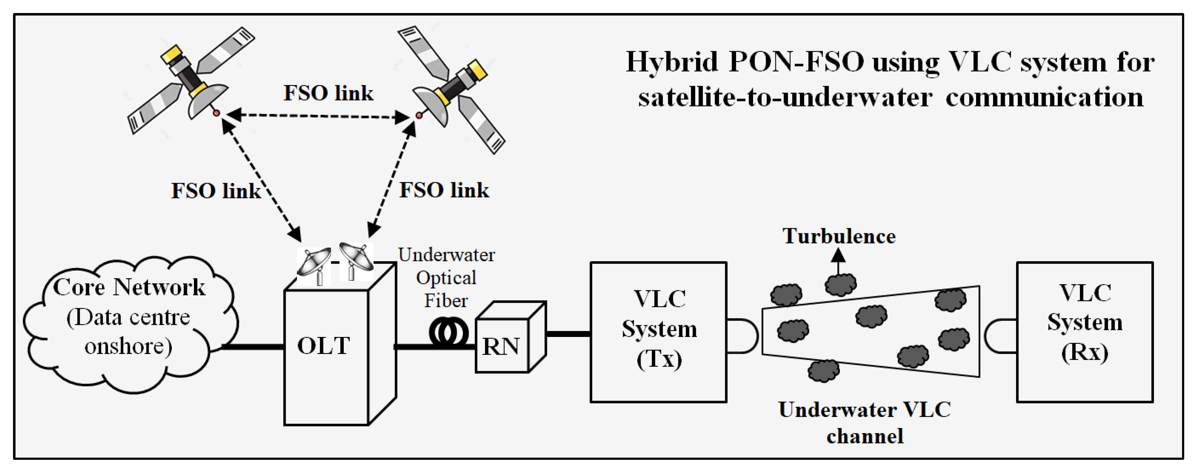
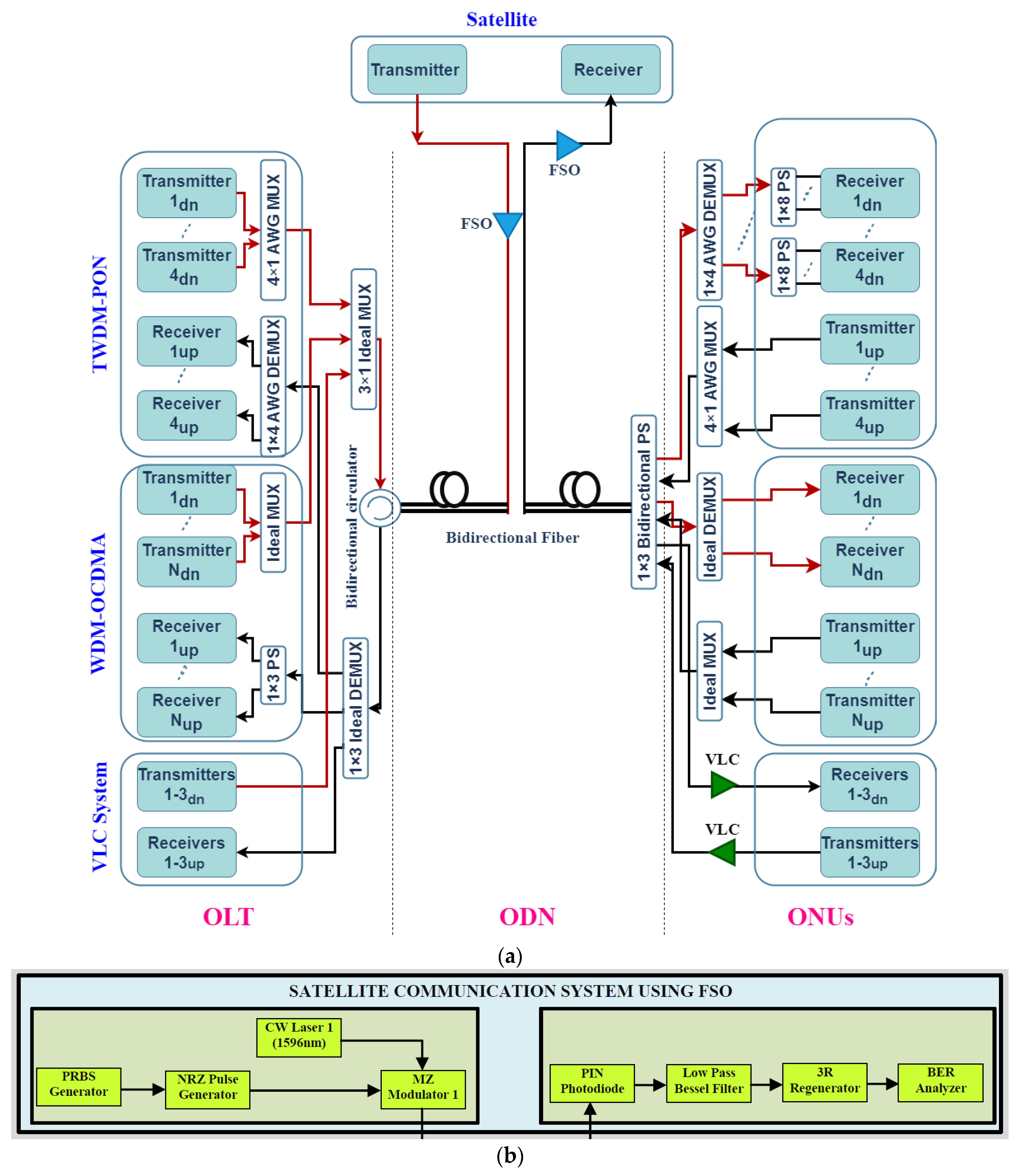
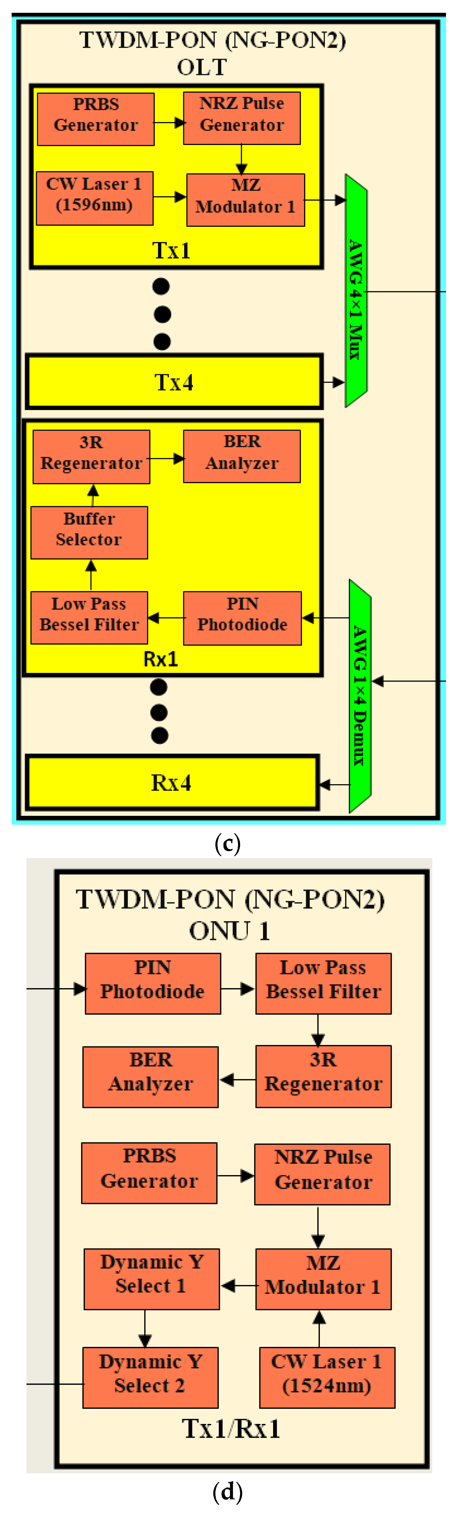
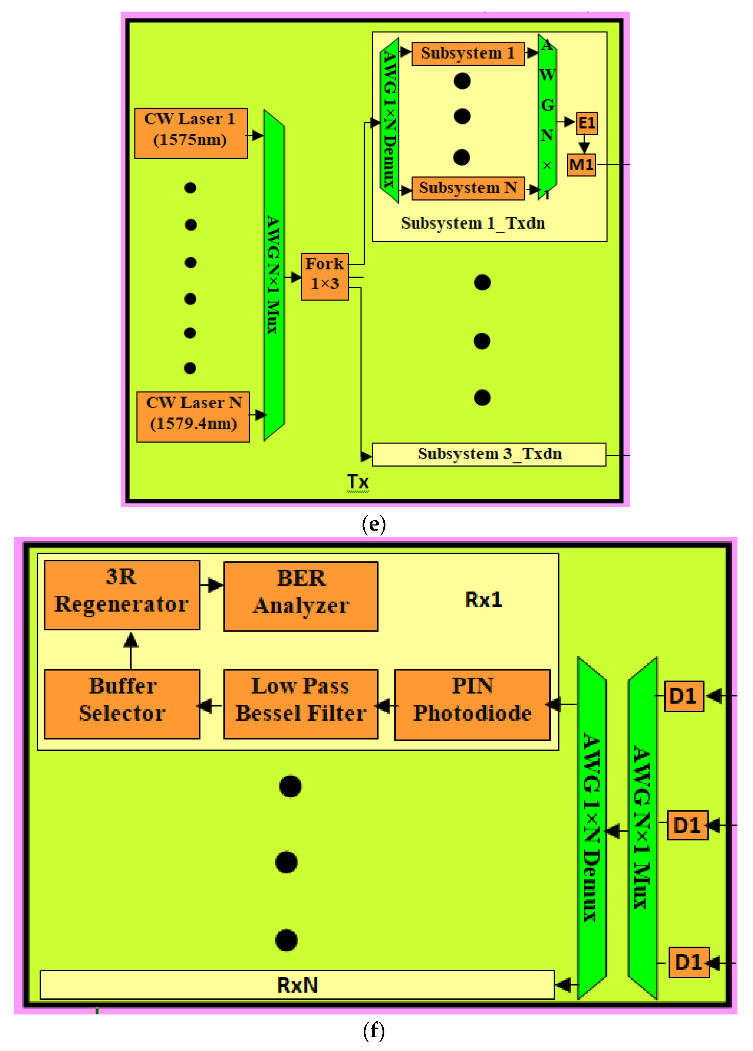
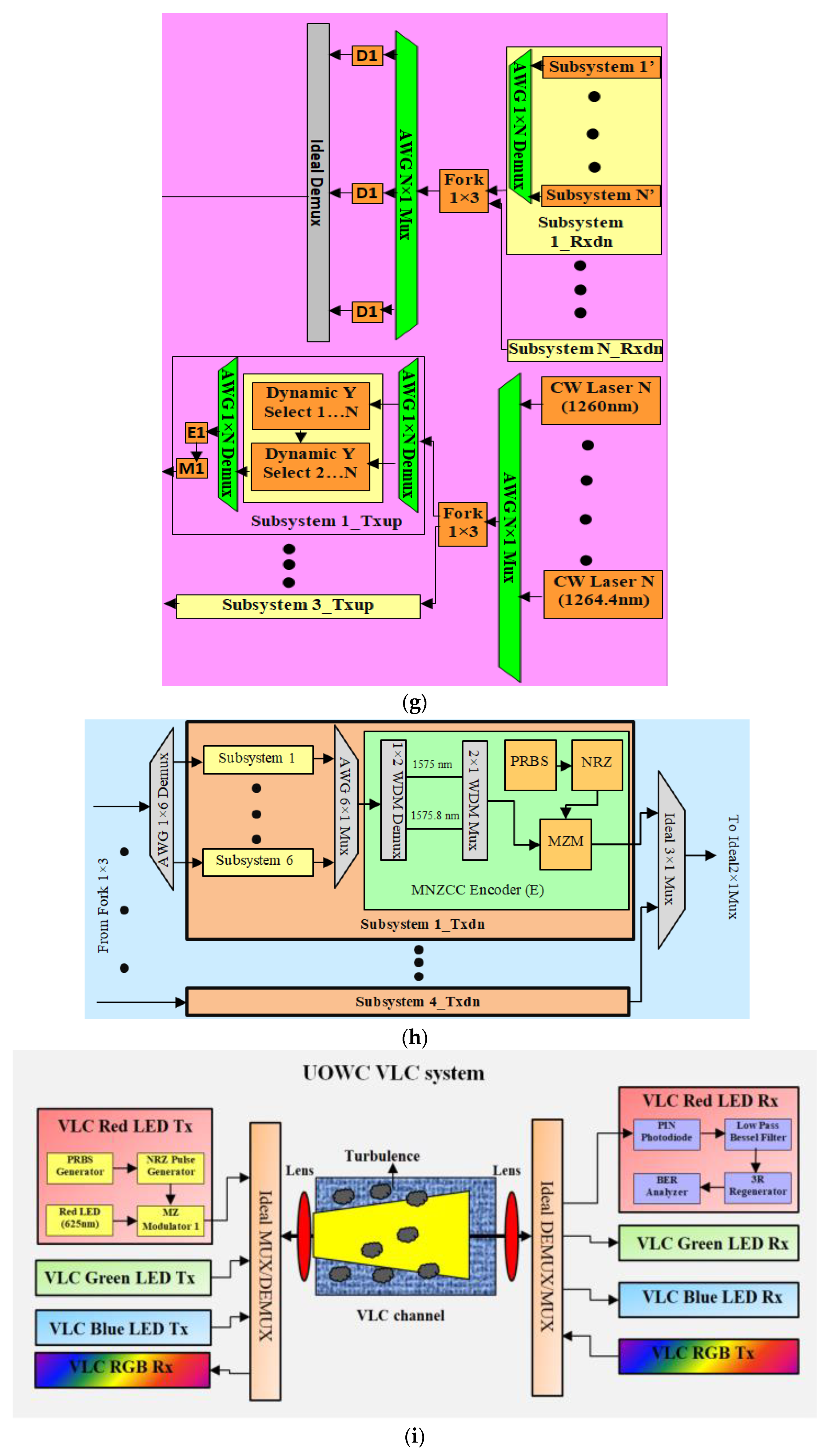
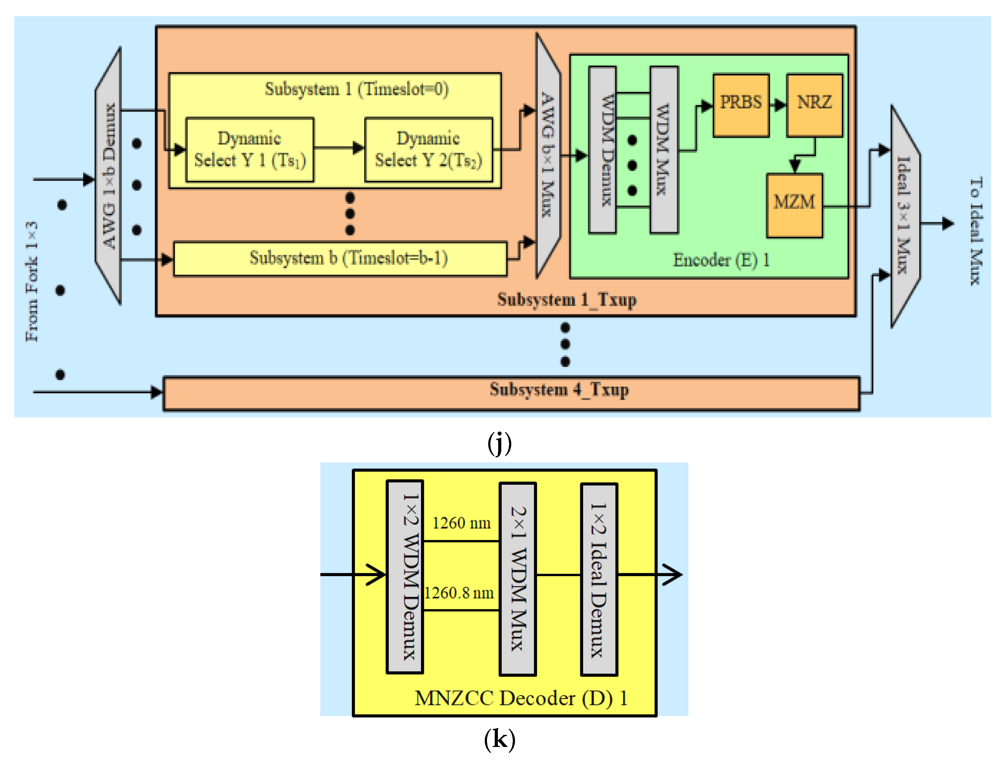
The novelty behind this work is to design a satellite-to-underwater optical communication model, which permits a platform for developing Internet access to various satellite-to-land-to-undersea devices distinct communication environments and channels facing difficult and vital challenges. For this, a hybrid PON-FSO system using a VLC for the long-haul as well as high bandwidth has been proposed. The designed model’s performance is measured under the impact of different fiber and water impairments with different OCDMA codes. The numerical and simulation results show that the proposed design offers >100 Gbps data rate, >100 km fiber transmission distance and enhances the communication security from satellite-to-underwater. It helps to fulfil long-haul, high-speed, mobile, secure and cost-effective desires of connected devices in distinct oceans on earth. Furthermore, it offers potential applications that support many end users, long-haul transmission with a high transmission rate and security in numerous satellite-to-underwater scenarios.
In this paper, the suggested system design is illustrated in Section 2. Section 3 presents the numerical analysis of the suggested design. Section 4 shows the results along with the discussion and the conclusion follows it in Section 5.

2. System Design

As demonstrated in Figure 1, the wireless optical signals, i.e., the FSO links, are transferred from an optical transmitter (Tx) located in a defined optical receiver (Rx) at an optical line terminal (OLT) over the vacuum in space as well as different climate conditions in earth’s atmosphere suitable for satellite-to-earth station communications. For this, an unconstrained line of sight (LOS) is required between the Txs and Rxs for transmission [20].

2.1. Downstream Design

Figure 2a illustrates the block diagram illustrating the suggested design employing four subsystems, viz. satellite, TWDM-PON, WDM-OCDMA as well as VLC. Figure 2b illustrates the satellite communication system using FSO links employing on-off keying modulation scheme. It indicates that the FSO links that carry the data from an earth station to the satellite in orbit. Here, at the earth station (Tx side), the incoming optical signal from a continuous wave (CW) laser diode (LD) is modulated with a pseudo-random bit sequence non-return to zero (PRBS-NRZ) digital signals through Mach-Zehnder modulator (MZM). Then an adequate signal is passed through modulated GG FSO turbulence channel towards the satellite and vice versa [21,22,23]. After this, at the satellite (Rx side), the optical signals are converted into electrical signals using a photodetector (PD). Then the low-pass Bessel filter (LPF) is used to filter out the noises from the original information [24,25,26]. A 3R regenerator is used to regenerate the distorted signal followed by the BER analyzer to analyze the system performance w.r.t. quality-factor (QF), BER, eye diagrams and eye height [26,27,28,29,30,31].
Figure 2c shows that, after receiving the satellite data from the satellite using FSO links from the communication system at an OLT/central office (CO) onshore data center at TWDM-PON design, four optical wavelengths (1596–1598.4 nm with 0.8 spectral widths) originated from CW LDs sources at an input power (Pin) of 10 dB. Then these optical wavelengths were modulated with PRBS-NRZ digital signals utilizing MZM and multiplexed by 4 × 1 array waveguide grading multiplexer (AWG MUX) at an aggregate data rate of 40 Gbps (=4 × 10 Gbps), as shown in Figure 2a. After this, these multiplexed signals passed through a series of bidirectional components viz. optical distribution network (ODN) viz. an optical circulator (OC), an ideal MUX, a bidirectional single-mode fiber (SMF) and a NOMA-VLC channel in UOWC to provide the data signals to the different underwater devices. To distribute these inputs signals, the 1 × 2 bidirectional power splitter (PS) followed by an AWG de-multiplexer (DEMUX) were utilized. It offered the TWDM design incorporating four sets of 1 × 8 power splitters (PSs) to support 32 underwater sea devices which are also known optical network units (ONUs), as shown in Figure 2d. Downlink Rx section consists of PIN PD, LPF, 3R regenerator and BER analyzer [21,22,23,24,25].
Figure 2e illustrates the WDM-OCDMA consisting of CO and ONUs with six pairs of Txs/Rxs as per MNZCC the code for three end users. The MNZCC code design for three downstream and upstream users is tabulated in Table 1.
WDM-OCDMA design incorporating MNZCC code can assist a maximum of 18 ONUs. Six wavelengths (1575–1577 nm with spectral width 0.4 nm) produced from six CW LDs were initially passed via 3 × 6 ONUs MUX, succeeded by 6 × 1 AWG MUX then sent to a 1 × 3 fork corresponding to three OCDMA coded groups for three subsystems as illustrated in Figure 2e. Each coded group incorporated a 1 × 6 AWG DEMUX, six subsystems as well as one encoder (E) for an underwater device. Subsystems 1 to 6 were utilized for modulating the multi-wavelength signal of OCDMA channels. A subsystem comprising PRBS, NRZ and MZM modulator components is shown in Figure 2h [25,32]. Then, the coded signals are multiplexed through a 6 × 1 AWG MUX. The signals spread to the MNZCC encoder, which incorporated the code design using a 1 × 2 WDM DEMUX along with 2 × 1 WDM MUX. In addition to this, incoming coded input modulation was performed using PRBS-NRZ and MZM components for each user. Three output signals from each encoder were forwarded to a 3 × 1 Ideal MUX as well as a 2 × 1 ideal MUX. Then the signals passed through three bidirectional components of the ODN section for full-duplex transmission. The downlink signals at the Rx side are distributed into three parts by using a 1 × 3 ideal DEMUX, as shown in Figure 2g. It is then forwarded to three OCDMA decoders (D1–D3) followed by a 6 × 1 AWG MUX as well as a 1 × 3 fork. For decoding, different types of WDM DEMUXs as well as WDM MUXs combinations were considered. Additionally, 1 × 2 ideal DEMUX along with a 6 × 1 MUX and 1 × 3 fork components were utilized [11,33].
Figure 2i illustrates the NOMA-VLC system based on RGB LEDs for UOWC using three red, green and blue LEDs to offer the required bandwidth and small beam divergence. For the downlink UOWC VLC system, NRZ-OOK modulation was incorporated to modulate three input LED (red, green and blue) signals. After that, the signals were multiplexed using a 1 × 3 ideal MUX to transmit over ODN and VLC channels. The VLC signal was transmitted through a sea channel considering primarily weak turbulence, scattering as well as absorption losses employing a lens at the transmitter as well as receiver sides to center the incoming light in the water channel [11,33].

2.2. Upstream Design

Figure 2d depicts the TWDM design incorporating 32 undersea devices transmitting aggregate 10 Gbps NRZ-PRBS data signals by modulating four CW LDs which generated four UP wavelengths (1527.2 nm–1529.6 nm with 0.8 nm spectral width) at Pin = 0 dBm using an MZM modulator. Furthermore, two Y-cascaded dynamic selects devices were employed with distinct switching times (0–1.6 ns) for all UP wavelengths. The received signals were forwarded to an Ideal MUX followed by AWG MUX at a remote node (RN). Then, on the OLT side, bidirectional SMF was used to receive the incoming signals. Following this, these signals passed through AWG DEMUX and passed to the CO side [11,33]. The receiver section for the uplink is presented in Figure 2c.
The -OCDMA design incorporated six wavelengths (1260–1262.4 nm with spectral width = 0.4 nm) that were originated as well as modulated with NRZ-PRBS combinations. Six wavelengths led to a 6 × 1 AWG MUX, a 1 × 3 fork and three subsystems, as shown in Figure 2g. Each Subsystem incorporated a 6 × 1 AWG DEMUX and six different subsystems for defined time switching of optical signals using two continuous dynamic selects, as defined in [11,33]. After passing across the 3 × 1 ideal MUX and ODN sections, the signals were recognized and examined at a CO part in the receiver section, as shown in Figure 2f [32,33]. The decoder section, which utilizes the MNZCC code, is shown in Figure 2k. In addition, the UP transmission in the NOMA-VLC section and satellite communication FSO system comprises similar components, such as the DN in the NOMA-VLC section and the DN satellite FSO system, respectively. The reverse VLC and FSO channels were used in the ODN section, as shown in Figure 2i. Table 2 tabulates the integrated FSO-SMF-VLC link parameters used.

3. Numerical Analysis
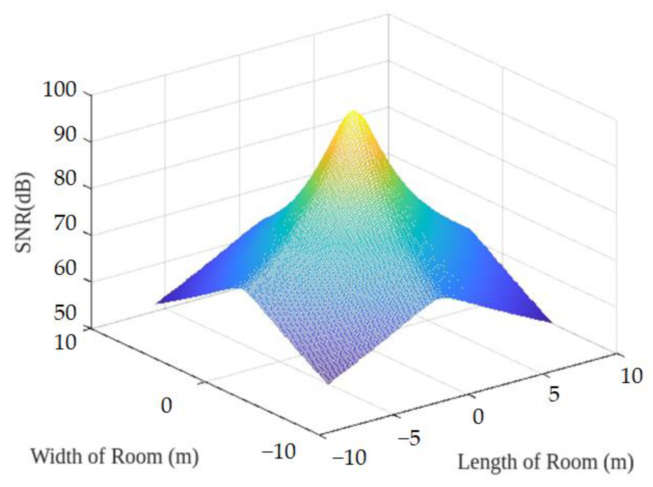
The hybrid FSO-PON using the NOMA-VLC system is numerically measured considering fiber CD, ISI, FWM, noise, VLC losses and VLC beam divergence.

3.1. Channel Model

The hybrid FSO-PON system is designed with the GG model. The GG channel distribution is described as [34,35]:
f s a s a = 2 xy x + y 2 Γ x Γ y . s a x + y 2 1 J x y 2 xys a 1 2
where s a is atmospheric turbulence, Γ(.) represents Gamma function, J x y is the modified Bessel function having order (x − y). Additionally, x and y represent the numbers of large as well as small-scale effective eddies, respectively, which are given for a spherical wave as [34,35,36]:
x = 1 exp 0.49 a 0 2 1 + 0.18 d 2 + 0.56 a 0 12 5 7 6 1
and
y = 1 exp 0.51 a 0 2 1 + 0.18 d 2 + 0.56 a 0 12 5 5 6 1 + 0.90 d 2 + 0.62 d 2 a 0 12 5 5 6 1
where a 0 2 and d represent the optical wave number and diameter of the spherical wave, respectively. The exp indicates exponential function.

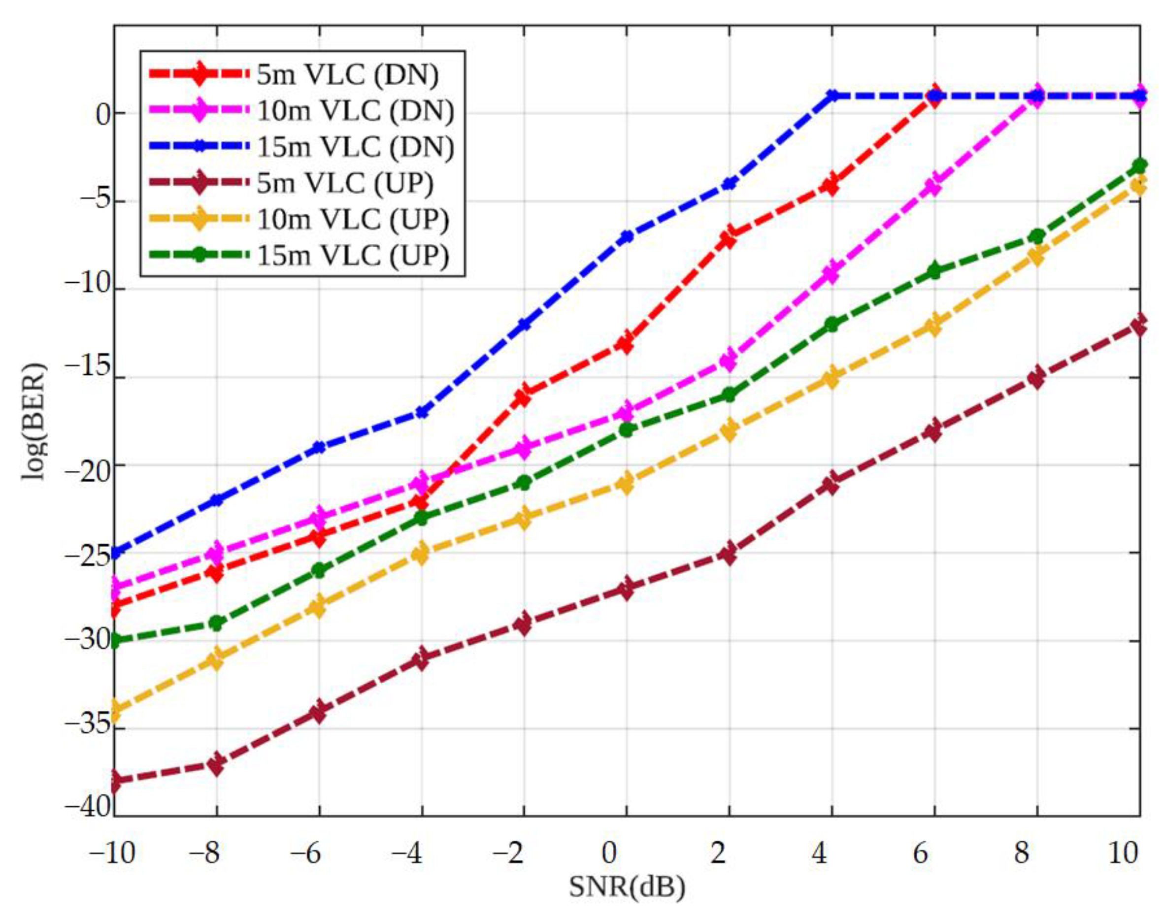
3.2. BER Performance Analysis

The light waves propagating in the oceanic medium undergo attenuation and signals’ broadening in the polarization, temporal, spatial and angular domains. These attenuated and broadened signals are input wavelengths dependents and derive absorption as well as light signals multi-scattering by water molecules or marine organic matter/minerals. Therefore, the aquatic channel extinction coefficient, y λ is regulated by absorption and two scattering coefficients viz. α λ and β λ as [37]:
y λ = α λ + β λ
Table 3 presents the conventional values of absorption and scattering in distinct kinds of water at the different operating wavelength ( λ ) ranges.
As the turbidity increases drastically, y λ rises in 0.1 m−1 to 2 m−1 range from clear water to turbid water. The propagation loss factor, L s λ , l for length l is given as [37]:
L s λ , l = e y λ l
Moreover, considering the LOS link in the VLC system, i.e., the transmitter transferring the light beam in a specific direction to the receiver, the received optical signal ( P r ) , obtained via multiplication of launch power with telescope losses is described as [37]:
P r = P t µ t µ r L p λ , l λ , d c o s Ω A c o s Ω 2 π d 2 1 c o s Ω 0
where P t means Tx power, µ t indicates Tx optical efficiency, µ r means Rx optical efficiency, d implies upright distance in Tx and Rx, Ω means angle in Tx and Rx trajectory, A means beam divergence angle and Ω 0 indicates the receiver aperture area. Furthermore, to evaluate the system BER performance under the direct-detection OOK modulation technique, the BER is presented as [37]:
B E R = 1 2 e r f c d 1 T d 0 T 2 d 1 T 1 / 2 + d 2 T 1 / 2
Here, d 1 = d d + d b g + d s and d 0 = d d + d b g , where d d and d b g indicate the additive noise sources due to dark counts as well as background illumination correspondingly. Also, e r f c presents an error function.
Again, the proposed work performance can be evaluated by measuring system BER, which relies on an SNR ratio. The output SNR at PD includes prime noise sources such as shot, thermal and dark currents in the system. In view of a Gaussian distribution of noise, S N R 0 in the absence of turbulence regimes at the receiver side is expressed as [39]:
S N R 0 = P t 2 h f B η P t + h f η e 2 4 K T B R n
where h, f, η and B imply the Plank’s constant, frequency, PD quantum efficiency as well as receiver filter bandwidth, respectively; e, Rn and K represent the electronic charge, input noise resistance and Boltzmann constant, respectively. However, in the presence of turbulence regimes, the mean SNR S N R can be presented as [39]:
S N R = S N R 0 P t 0 P t + k 0 2 D r S N R 0 2
where P t 0 is the signal optical power without turbulence and P t implies the mean of Pt. Moreover, the error probability is described as [39]:
P e = P ( 1 0 ) P 0 + P ( 0 1 ) P 1
Where P 0 and P 1 mean the binary ‘0’ and ‘1’ probability, respectively. Again, P ( 0 1 ) and P ( 1 0 ) imply the conditional probabilities. Assuming the transmitter is sending ‘0’s and ‘1’s with the alike probability of ½, P e is written as [39]:
P e = 1 2 P ( 1 0 ) + P ( 0 1 )
Also, the Gaussian distribution for both binary ‘0’ and ‘1’ signals along with noise, the P e or BER without turbulence is [39]:
B E R 0 = 1 2 S N R 0 2 2
Though, without taking turbulence regimes, FSO link BER is [39]:
B E R F S O = 1 2 0 p I s erfc S N R s 2 2 i s d s
where p I s implies irradiance probability distribution with a signal strength of s. Again, i s is the signal current mean value. By using Meijer G-function using e z = G 1 , 0 1 , 0 z 0 expression, erfc in Equation (13) is given as [40]:
erfc y = 1 π G 1 , 2 2 , 0 y 0 , 1 2
and for the FSO, the link average BER is expressed as:
B E R F S O = 1 2 0 f h a h a   e r f c S N R s 2 2 i s d s
Furthermore, the BER performance of TWDM-PON is represented as [41]:
B E R T W D M P O N = 1 2 e r f c S N R 0 2
Finally, the BER performance of integrated PON-FSO utilizing VLC link can be evaluated as [41]:
B E R t = B E R T W D M P O N + 1 C r B E R F S O
where C r represents the channel correlation coefficient from 0 and 1, which is utilized to determine the performance of the system for distinct channels reception at the PD receiver end for distinct turbulence conditions. As C r increases, the system output diminishes because of channels overlapping at the reception side. From Equations (7), (15) and (16) for the proposed system, the total BER with GG fading for FSO channels with C r = 0.1 is evaluated as [42]:
B E R T o t a l = 1 2 e r f c S N R 0 2 + 1 2 0 f h a h a   e r f c S N R s 2 2 i s d s + 1 2 e r f c d 1 T d 0 T 2 d 1 T 1 / 2 + d 2 T 1 / 2

3.3. Impact of Losses

  • Geometric loss (GL): GL in FSO links rises owing to the transmitted beam spreading between transmitter and receiver. However, smaller transmitter divergences and larger receiver apertures over an FSO link range (Z in km) and divergence ( θ in mrad) cause minimum GL. In general, GL (in dB) is given as [11,43,44,45]:
    G L   d B = 10 log D r D t + Z θ 2
    where D t (in meters) indicates the transmitter aperture diameters.
  • Chromatic dispersion (CD): In the fiber-VLC link the CD, d F i b e r in (ps/nm) at a referred wavelength of 1550 nm is presented as below [46]:
    d F i b e r = l d + c λ 1550
    where l , d   and   c present SMF length followed by dispersion and slope coefficient of different wavelengths. The calculated dispersion at 100 km fiber, 10 km FSO and 10 m VLC range at 10/2.5 Gbps transmission rate are tabulated in Table 4.
In Table 4, the measured positive values indicate the faster progress of short wavelengths than long wavelengths and vice versa for negative values. Therefore, the maximum sustainability attained in downstream (tolerance range = 1176 ps/nm) as well as upstream (tolerance range = 18,817 ps/nm) fiber range is ≤100 km and >100 km respectively over integrated fiber-VLC link.
  • Impact of ISI: ISI owing to the existence of overlapped contiguous bit intervals optical pulses, cause pulse broadening represented as Δb as [46]:
    Δ b = d l Δ λ
    where Δ λ indicates the pulse spectral line width. As for TWDM-PON as well as WDM-OCDMA, Δ λ is 0.8 nm and 0.4 nm, respectively, while for FSO and VLC systems, the ISI can be neglected.
Table 5 tabulates the measured Δ λ over 10–110 km fiber distance along with 10 km FSO and 10 m VLC range analogous to the DN transmission (highly affected than uplink) at 10 Gbps data rate.
It is noted that the values of Δ λ rise as fiber length increases, resulting in a degradation in system performance.
  • Impact of FWM: The full range of FWM wavelengths ( λ F W M ) for i wavelength links in the proposed system is presented as [47]:
    λ F W M = i 2 2 i 1
Here, hybrid TWDM-PON produces three FWM wavelengths, while the WDM-OCDMA produces a maximum of four for the MNZCC code. A larger number of wavelengths is caused by more FWM noise in the system. As in FSO and VLC systems, only single and three wavelengths are used, respectively. Hence, produces minimum FWM noise. Additionally, with increasing the transmission rate, the FWM side lobes rise, which results in degrades in system performance.
  • Channel noise and beam divergence in VLC: Table 6 and Table 7 show the comparisons of the proposed system with integrated fiber-VLC link (50 km fiber + 10 km FSO + 10 m VLC), having Tx and Rx aperture diameter of 10 cm and 20 cm, respectively for downstream and upstream transmission, respectively.
It is depicted that, with the rise in beam divergence, the Tx and Rx losses rise simultaneously and system performance diminishes for both uplink as well as downlink data transmission. The best system performance may be attained for uplink-integrated FSO-PON using VLC with minor beam divergence as well as losses w.r.t. high Pr, optimum SNR and low BER.

3.4. Sensitivity of Receiver

Receiver sensitivity (RS) at the receiver side is presented as the lowest tolerable value of received signals strengths is [48]:
R S = R S dB I L t o t a l + P P > 32.5   dBm
where I L t o t a l and P P represent total insertion loss as well as power penalty, respectively. The insertion loss for DS and UP such as I L d n and I L u p are given as [48]:
I L d n dB = I L M Z M + M U X + C i r c u l a t o r + D E M U X
and
I L u p dB = I L D y n a m i c Y + M U X + C i r c u l a t o r
Thus, the calculated R S d n and R S u p for DS and UP transmission, respectively, over 10 km in 16 × 10/10 Gbps TWDM-PON is given as [48]:
I L d n dB = 3 + 2 + 1 + 3 = 9   dB
R S d n = 24 9 + 2 = 35 > 32.5   dBm
I L u p dB = 3 + 2 + 1 = 6   dB
R S u p = 24 6 + 2 = 32 > 32.5   dBm
Table 8 summarizes the system performance parameters QF, BER, RS and OSNR obtained for TWDM-PON using MNZCC code at 1596 nm for DS and 1527 nm for UP channels operating at symmetric 10 Gbps per channel rate. The suggested system is a symmetric system for diverse link distances with acceptable log (BER) of −9. The obtained RS for DS and UP transmission easily achieve minimum value sensitivity conditions endorsed by ITU-T 989.2 [48,49].

3.5. Power Budget

In the proposed work, PB can be evaluated as [48]:
A dB = α L + α s n s + α c n c
where α , α s and α c denote the fiber attenuation, splices’ attenuation and connectors’ attenuation, correspondingly. L , n s and n c denote the length of the fiber, number of splices and number of connectors correspondingly.
The total obtained attenuation, A dB in the system with no splices loss is [48]:
A dB = 0.2 50 + 10 = 20   dB
Also, PB is calculated below [48]:
P B dB = T r a n s m i t t e d   P o w e r R S
For the, DS and UP, the P B is given as below [48]:
P B d n dB = 10 36 = 46   dB
and
P B u p dB = 0 33 = 33   dB
Insertion loss produced due to splitter because of n s p l i t t e r s , number of splitters is measured as [48]:
P L s p l i t t e r = 10   log 1 / n s p l i t t e r s
P L s p l i t t e r = 10 log 1 / 128 = 21   dB
Thus, splitter power budget ( S P B ) with Link Margin, L m d B = 3   dB is given as [48]:
S P B = P B A t o t a l L m
For D/S and U/S, the S P B d n and S P B u p are given in Equations (38) and (39), respectively, as [48]:
S P B d n = P B d n A t o t a l L m = 46 20 3 = 23   dB
and
S P B u p = P B u p A t o t a l L m = 33 20 3 = 10   dB

3.6. Impact of Channels

To calculate the performance of the proposed system using distinct OCDMA codes, gain G and noise figure N F together play an important role. Thus, G and N F are described as [50,51]:
G = 10 l o g 10 P o P i dB = P o d B P i dB
and
N F = 10 l o g 10 S N R i S N R o dB = S N R i dB S N R o dB
where SNRi means input SNR respectively.
Table 9 tabulates the comparisons of integrated FSO-PON using NOMA-VLC system with seven codes in terms of G , N F , P i , output power ( P o ), input OSNR (OSNRi) and output OSNR (OSNRo) for various DN wavelengths over 10 km FSO, 10 km fiber and 10 m VLC transmission range for 300 devices in the satellite-to-underwater network.
The tabulated values in Table 9 reveal that the MNZCC code performs best in the proposed design at a 10 Gbps data rate over 10 km fiber and 10 m VLC range.

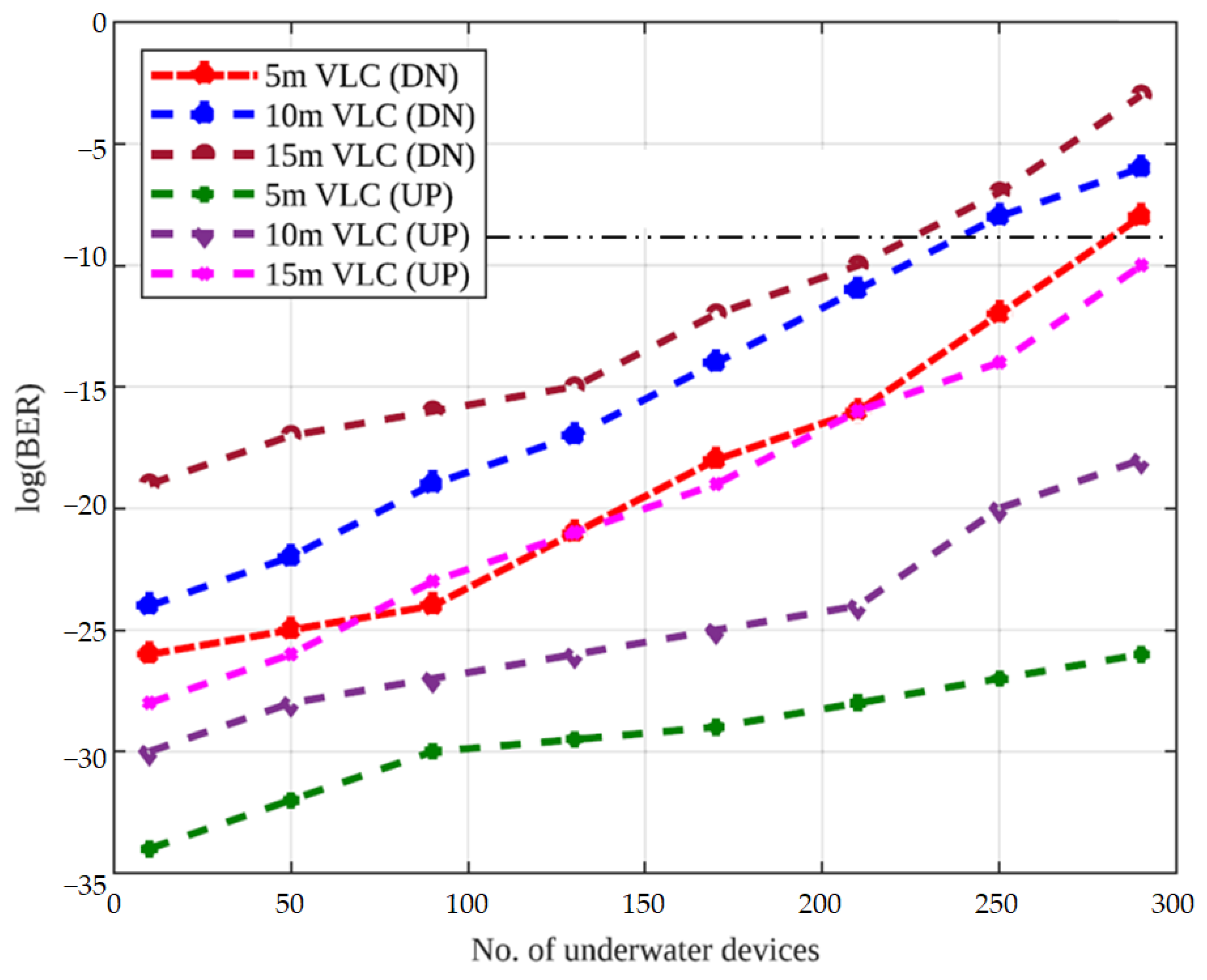
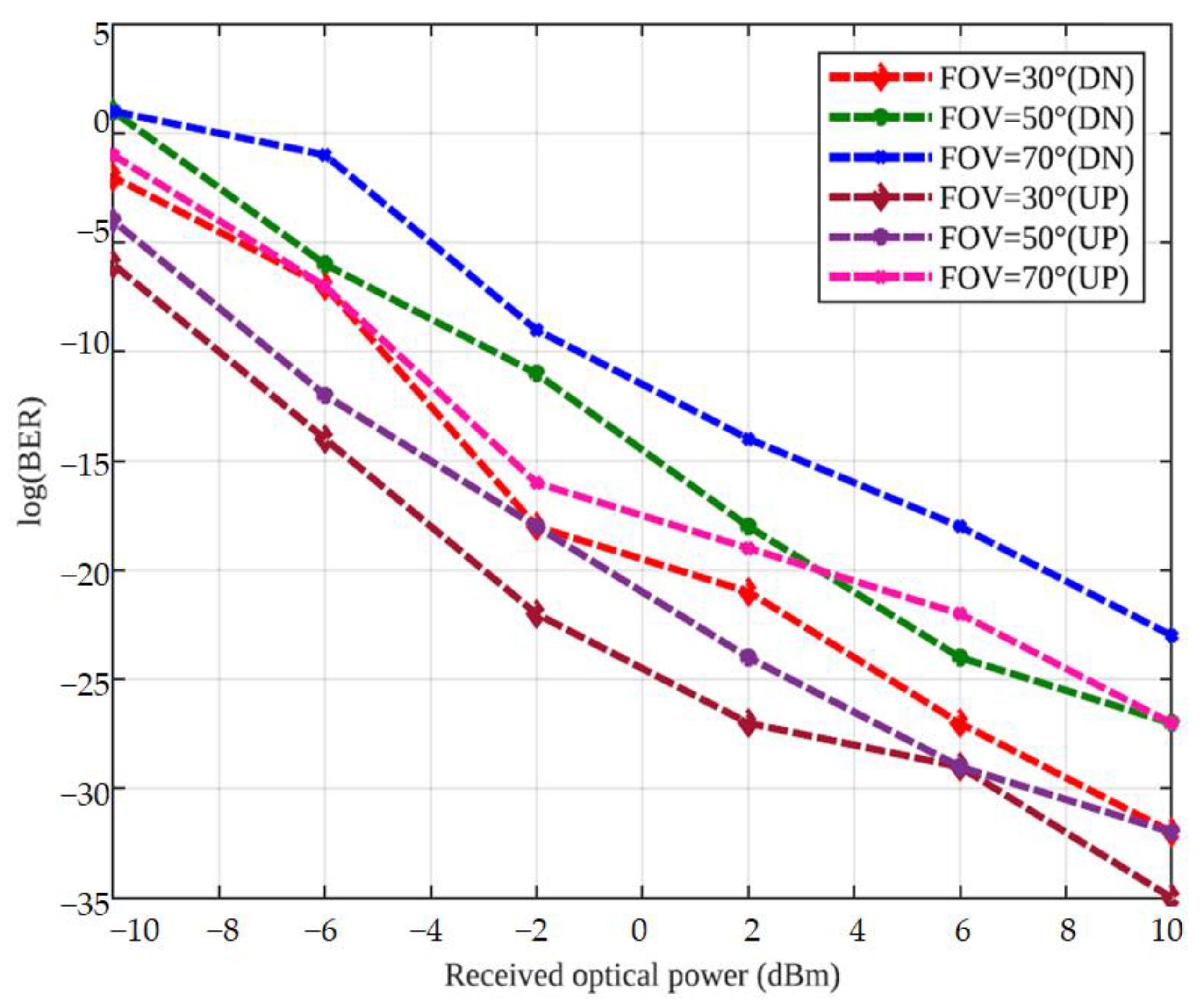
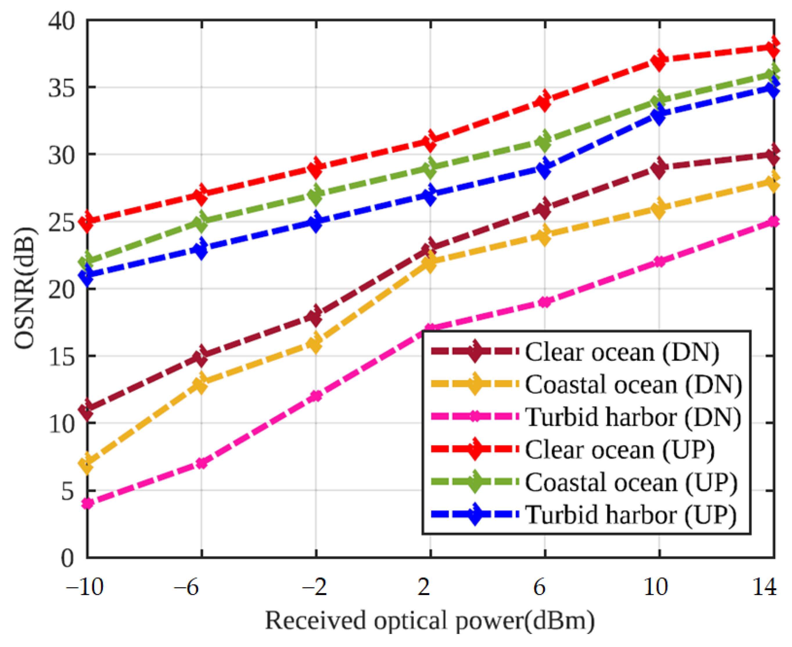
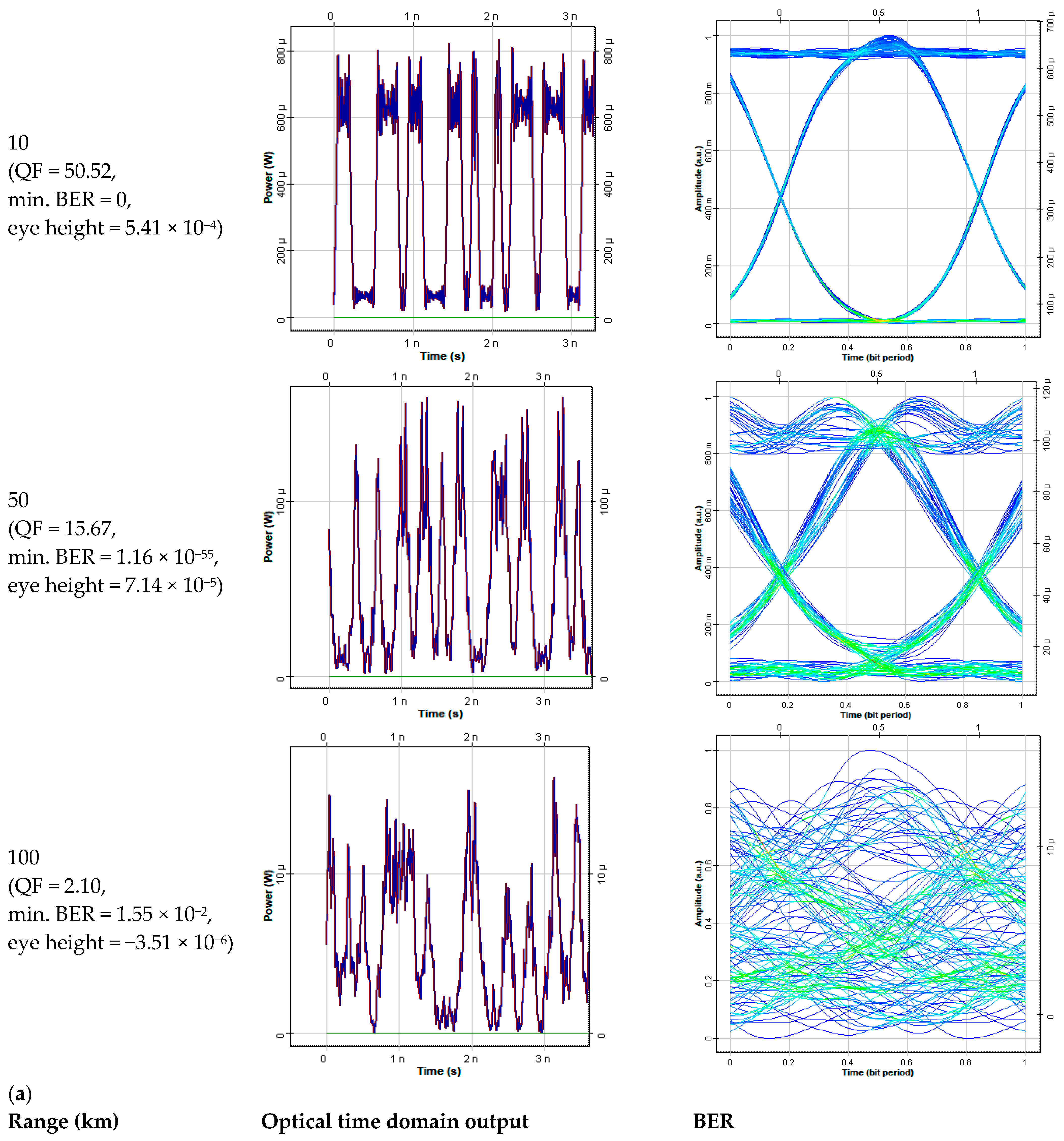
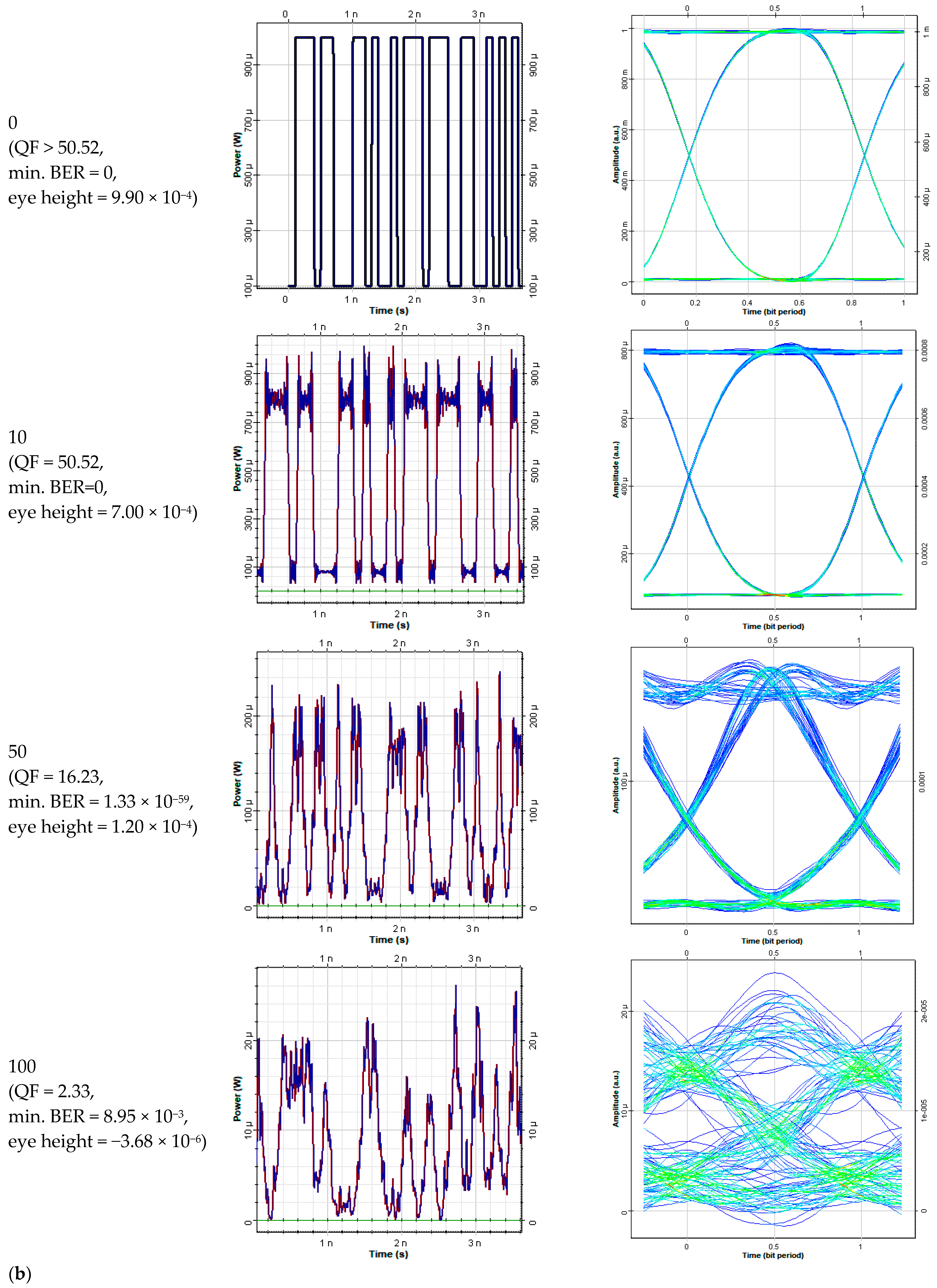
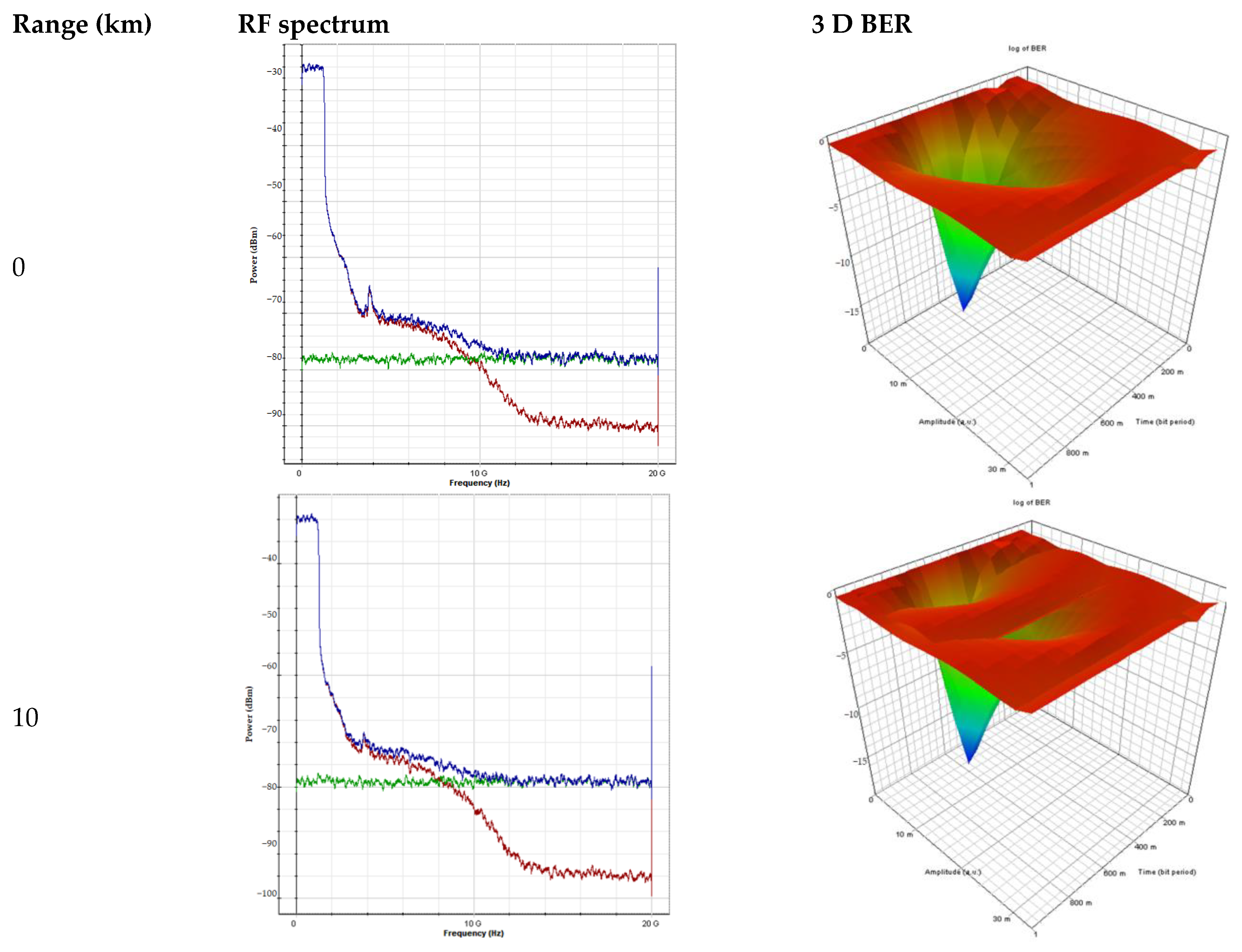
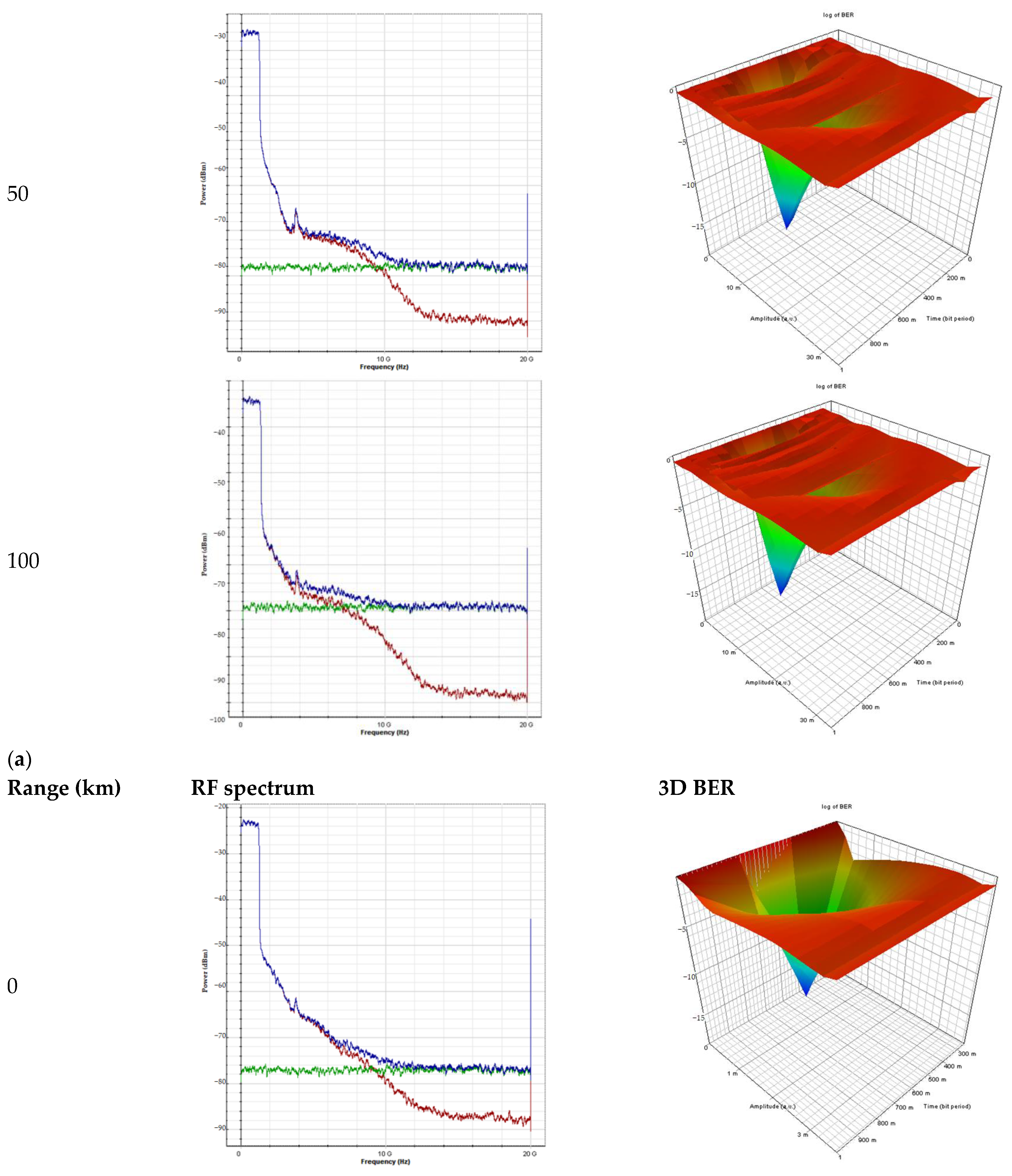
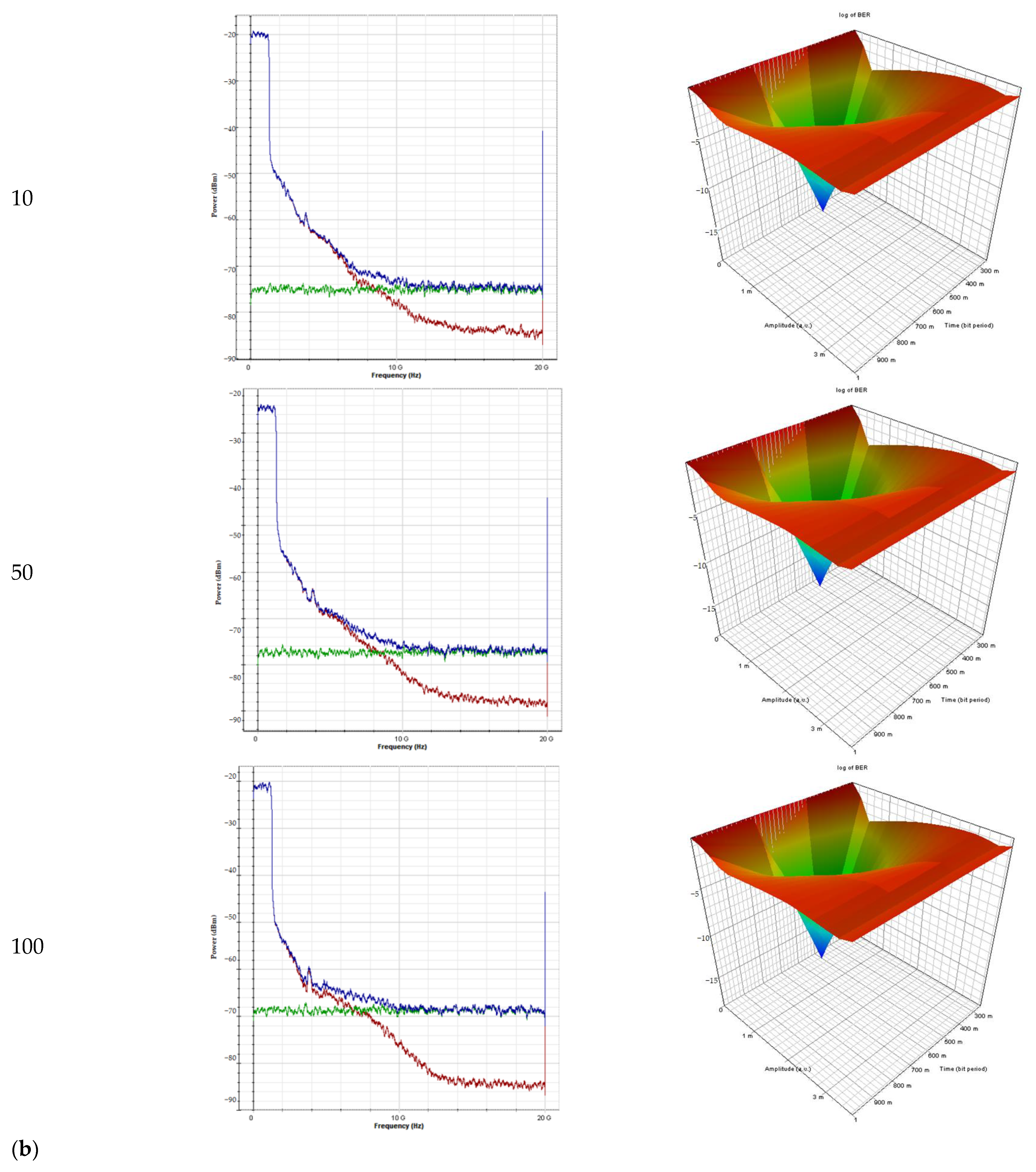
4. Results and Discussion

This section shows the derived BER expressions for three users of MNZCC code employed in a hybrid FSO-PON system with NOMA-VLC evaluated in OptiSystem 15.0 and MATLABTM r2022a software. Table 2 tabulates the system configuration parameters for the result analysis. The various hypotheses considered for the simulation work of the proposed systems are given below:
  • For performance analysis, the effect of fiber, FSO and VLC channels deteriorations, such as ISI, CD, FWM, noise (thermal, shot etc.), beam divergence as well as geometric loss, are considered;
  • To measure the performance in PON, FSO and VLC, various different DN and UP wavelengths are selected, i.e., 1596 nm (DN) and 1527.2 nm (UP) for TWDM-PON; 1575 nm (DN) and 1260 nm (UP) for WDM-OCDMA; 1550 nm (both DN and UP) for FSO; and 625 nm, 525 nm and 455 nm (both DN and UP) for NOMA-VLC channels with 0.2 power allocation coefficient;
  • The environmental conditions for satellite-to-land communication using FSO links and underwater VLC links are considered as clear, except otherwise stated;
  • PD’s FOV in NOMA-VLC is considered as 500, except when otherwise stated.
Figure 3 shows the SNR distribution of the VLC system in length, breadth and width (15 m, 15 m, 15 m) dimension of the receiver section in UOWC.
The log (BER) curves for the satellite-to-underwater proposed system are plotted against the SNR for varied DN and UP VLC ranges (5–15 m) in Figure 4. The fiber and FSO ranges are considered 100 km and 10 km, respectively, with varied VLC ranges under the impact of Clear Ocean. It shows that the BER curves improve as the SNR decreases. The BER performance of the UP VLC channel is superior to DN transmission. This is due to the fact that power (Pin = 0 dBm per channel) and data rate (=2.5 Gbps per channel) allocated to upstream channels are lesser than those of the downstream channels. The figure also presents that better performance of the 5 m VLC range followed by 10 m and 15 m for both DN and UP channels. The obtained SNR values for DN transmission are −1, 1 and 4 dB for DN. For UP transmission, these are 10, 8 and 6 dB over for 5, 10, and 15 m VLC ranges, respectively, considering an acceptable log (BER) of −9. This is due to the propagation of light underwater effects diminishes by scattering, absorption and turbulence effects. Thus, the incoming optical signals underwater undergo scattering and absorption losses as it strikes the water molecules as well as particles, owing to which there is a loss in signal intensity and, hence, degrades the system performance [1].
Figure 5 presents the log (BER) performance with different numbers of underwater connected devices of the bidirectional 10/2.5 Gbps per wavelength hybrid FSO-PON system utilizing NOMA-VLC over varied VLC underwater range from 5 to 15 m, fixed 100 kmfiber range and 10 km FSO range in clear ocean water. The VLC range changes from 5 to 15 m for different underwater devices. The performance of the DN and UP transmission diminishes in terms of an increase in log (BER) values. Additionally, the number of underwater devices increases from 10 to 290. The system performance again decreases for all varied VLC ranges. However, VLC transmission in the UP direction shows better performance than the DN direction for all varied VLC ranges. The maximum supportable underwater devices for UP and DN transmission over 5, 10 and 15 m VLC ranges are 280, 250 and 201. For DN, more than 290 for UP transmission, respectively, resulting in a minimum log (BER) of −9. Therefore, the maximum supportable underwater devices for UP and DN links are more than 290 and 280, respectively, over a 5 m VLC range. The system performance decreases primarily due to the presence of fiber impairments, such as ISI, FWM etc., that increase the fiber nonlinearities and noise.
Figure 6 presents the BER performance analysis for the suggested system utilizing distinct values of FOV angles, considering 10 km FSO, 100 km fiber and 5 m VLC ranges in the clear ocean for both DN and UP transmissions. The BER of the considered system increases from −35 to 0, with an increase in FOV from 300 to 700. At the minimum acceptable log (BER) of −9, the ROP for 300, 500 and 700 is 2, 4 and 5 dBm in DN, while ROP for 300, 500 and 700 is 9, 8 and 5 dBm in UP. Thus, UP shows better performance w.r.t. DN, out of which 300 FOV with high ROP shows the best performance followed by 500 and 700.
Figure 7 presents the OSNR (dB) versus ROP (dBm) of the proposed hybrid FSO-PON system incorporating NOMA-VLC over 100 km fiber range, 10 km FSO range and 5 m VLC range in the clear ocean, coastal ocean and turbid harbor water types for both DN and UP transmission. It is clearly measured that, as the water type changes from clear ocean to coastal ocean and then to turbid harbor, the performance of the FSO-fiber-VLC links in DN and UP direction degrades in terms of decrease in OSNR for different ROPs values. Furthermore, the ROP increase from −10 to 14 dBm and the OSNR values for different water types improves from 4 to 38 dB. Moreover, UP transmission shows better performance than DN for all water types, having superior performance under clear ocean water, followed by the coastal ocean and turbid harbor, respectively. Thus, the maximum achieved OSNR for the clear ocean, coastal ocean and turbid harbor is 39, 36 and 35 dB, respectively, at an ROP of 14 dBm in the UP direction. While in the DN direction, the maximum achieved OSNR for the clear ocean, coastal ocean and turbid harbor is 30, 27 and 25 dB, respectively, at 14 dBm ROP. It signifies that the maximum obtained OSNR in UP direction clear ocean underwater condition is 39 dB. In addition, the major cause of the decrease in system performance for ROP and OSNR is, again, the presence of fiber impairments as well as FSO link losses.
Figure 8a,b depicts the performance of the suggested system over variable fiber ranges in terms of output optical time domain (OTD), along with corresponding eye patterns for DN and UP channels, correspondingly. It is clear that the timing diagrams of signals at ONUs become distorted with the increase in SMF distance. This owes to the presence of fiber impairments and noise in SMF. Again, the clear timing diagram is obtained for back-to-back transmission and it illustrates the best performance out of the other diagrams. Out of all the channels, uplink channels show better performance than downlink channels.
Moreover, the respective eye patterns over 0, 10, 50 and 100 km fiber length are also depicted in Figure 8a for downlink and in Figure 8b for uplink to support the above discussions. As the eye-opening diminishes, i.e., eye distortion increases, BER improves and QF decrease with the improvement in fiber length. The better performance can be seen for uplink channels.
Figure 9a,b presents the performance of the proposed system over variable fiber distance in terms of RF spectra and its respective 3D BER patterns for DN and UP received signals, respectively. The fiber distance increases from back-to-back to 100 km and the RF spectra become distorted and comprise low output power. Again, UP transmission (minimum ROP = −95 dBm) shows a better performance than DN transmission (minimum ROP = −100 dBm) over various fiber lengths. The 3D BER patterns for both DN and UP (Figure 9a,b) present that data transmission in UP outperforms DN by providing clear and fewer ripples BER patterns.
From Table 10 and Table 11, it is shown that the suggested system utilizing the MNZCC code has better performance than other codes and system designs, respectively. In the recommended system, the MNZCC code has less code weight and length, a maximum number of connected devices and zero cross-correlation properties. Additionally, regarding the rate and distance of transmission, the recommended design provides a maximum fiber transmission distance of 100 km, with 10 km FSO and 15 m VLC range at a traffic rate of 10/2.5 Gbps to support more than 250 simultaneous devices in both UP and DN directions.
Moreover, the practical realization of the proposed work adds complexity to the CO side, as it would also be “natural” as well as less expensive to simply establish the TWDM-WDM channels on FSO-VLC using OCDMA codes. Furthermore, separate input light sources and modulators were required to generate a single wavelength signal in the PON-FSO-VLC system. This increases the system configuration cost and complexity. In addition to this, the proposed work’s complexity highly depends on the OCDMA code sequence length, internet of underwater communication and multi-beam satellite communication. Thus, to reduce the system’s complexity, reasonable input laser sources with modulators, 1D-based MNZCC code with suitable code length, line of sight single beam underwater and satellite communication are considered. Table 11 shows the complexity level of the proposed work ranges from moderate to high depending on various factors stated above. For the proposed work, stable low power consumption and cost-effective design are realized from sea-to-space communication.
Table 12 illustrates the comparisons of the integrated FSO-PON system using NOMA-VLC, considering gain ( G ), noise figure ( N F ), P i , output power ( P o ), input OSNR (OSNRi) and output OSNR (OSNRo) for distinct DN/UP wavelengths.

5. Conclusions

A hybrid TWDM-WDM-PON incorporating OCDMA employing NOMA-VLC is incorporated to offer a faithful FSO-fiber-VLC link for satellite-to-undersea under the impact of different water types in oceans, fiber impairments and noise. It is concluded that the design model offers 10 km FSO, 100 km fiber and 5 m VLC range successfully with 10 dBm SNR for 290 connected devices. In addition to this, OSNR and received power of 39 dB and −9 dBm, respectively, are obtained at a minimum BER limit of 10−9. Moreover, uplink transmission outperforms the downlink with an optimum performance less than 300 field of view. The best achieved receiver sensitivity, splitter power budget, gain and noise figure values are −32 dB, 10 dB, −1 dB and 1 dB, respectively. Moreover, compared with existing works regarding the codes and system design, the proposed system design depicts superior performance.

Author Contributions

Conceptualization, V.A., M.K. and H.M.R.A.-K.; methodology, V.A., M.K., H.M.R.A.-K. and S.A.A.; software, V.A., M.K., H.M.R.A.-K. and S.A.A.; validation, V.A., M.K., H.M.R.A.-K. and S.A.A.; formal analysis, V.A., H.M.R.A.-K. and S.A.A.; investigation, V.A. and M.K.; resources, V.A., H.M.R.A.-K. and S.A.A.; writing—original draft preparation, V.A., M.K. and H.M.R.A.-K.; writing—review and editing, V.A., M.K. and H.M.R.A.-K.; visualization, M.K., H.M.R.A.-K. and S.A.A.; supervision, S.A.A.; project administration, H.M.R.A.-K. All authors have read and agreed to the published version of the manuscript.

Funding

This research received no external funding.

Data Availability Statement

All data are available in this paper.

Conflicts of Interest

The authors declare no conflict of interest.

References

  1. Liu, X.; Lin, M.; Kong, H.; Ouyang, J.; Zhu, W.P. Performance Analysis of Mixed FSO-RF Transmission in Multiuser Satellite–Aerial–Terrestrial Networks. Opt. Commun. 2021, 496, 127141. [Google Scholar] [CrossRef]
  2. Fayad, A.; Cinkler, T.; Rak, J.; Jha, M. Design of Cost-Efficient Optical Fronthaul for 5G/6G Networks: An Optimization Perspective. Sensors 2022, 22, 9394. [Google Scholar] [CrossRef]
  3. Kumar, L.B.; Krishnan, P. Multi-Hop Convergent FSO-UWOC System to Establish a Reliable Communication Link between the Islands. Opt. Commun. 2020, 474, 126107. [Google Scholar] [CrossRef]
  4. Shi, Y.; Armghan, A.; Ali, F.; Aliqab, K.; Alsharari, M. Enriching Capacity and Transmission of Hybrid WDM-FSO Link for 5G Mobility. Photonics 2023, 10, 121. [Google Scholar] [CrossRef]
  5. Aboelala, O.; Lee, I.E.; Chung, G.C. A Survey of Hybrid Free Space Optics (FSO) Communication Networks to Achieve 5G Connectivity for Backhauling. Entropy 2022, 24, 1573. [Google Scholar] [CrossRef]
  6. Dixit, V.; Kumar, A. BER Analysis of Dynamic FOV Based MIMO-NOMA-VLC System. AEU-Int. J. Electron. Commun. 2021, 142, 153989. [Google Scholar] [CrossRef]
  7. Pradhan, J.; Holey, P.; Kappala, V.K.; Das, S.K. Performance Analysis of ACO-OFDM NOMA for VLC Communication. Opt. Quantum Electron. 2022, 54, 531. [Google Scholar] [CrossRef]
  8. Irawan, A.; Abas, M.F.; Hasan, N. Robot Local Network Using TQS Protocol for Land-to-Underwater Communications. J. Telecommun. Inf. Technol. 2019, 1, 23–30. [Google Scholar] [CrossRef]
  9. Hsu, C.-H.; Jiang, S.-Y.; Hsieh, S.-E.; Yeh, C.-H.; Lai, Y.-T.; Chen, L.-Y.; Liaw, S.-K.; Chow, C.-W. Hybrid Self-Protected Fiber-FSO WDM-PON System with Fiber Breakage Prevention. Photonics 2022, 9, 822. [Google Scholar] [CrossRef]
  10. El-Nahal, F.; Xu, T.; AlQahtani, D.; Leeson, M. A Bidirectional Wavelength Division Multiplexed (WDM) Free Space Optical Communication (FSO) System for Deployment in Data Center Networks (DCNs). Sensors 2022, 22, 9703. [Google Scholar] [CrossRef]
  11. Kumari, M.; Sharma, R.; Sheetal, A. Performance Analysis of High Speed Backward Compatible TWDM-PON with Hybrid WDM–OCDMA PON Using Different OCDMA Codes. Opt. Quantum Electron. 2020, 52, 482. [Google Scholar] [CrossRef]
  12. Butt, R.A.; Idrus, S.M.; Zulkifli, N.; Waqar Ashraf, M. Comprehensive Bandwidth Utilization and Polling Mechanism for XGPON. Int. J. Commun. Syst. 2018, 31, e3475. [Google Scholar] [CrossRef]
  13. Morsy, M.A.; Alsayyari, A.S. Performance Analysis of Coherent BPSK-OCDMA Wireless Communication System. Wirel. Netw. 2020, 26, 4491–4505. [Google Scholar] [CrossRef]
  14. Deka, R.; Verma, A.; Anees, S. Performance Analysis of Decode-and-Forward Based Hybrid RF/FSO-VLC System. In Proceedings of the 2019 IEEE International Conference on Advanced Networks and Telecommunications Systems (ANTS), Goa, India, 16–18 December 2019; pp. 1–5. [Google Scholar] [CrossRef]
  15. Deka, R.; Anees, S. Performance Analysis of DF Based Mixed VLC-FSO-VLC System. In Proceedings of the IEEE 92nd Vehicular Technology Conference (VTC2020-Fall), Bangalore, India, 19–24 July 2020. [Google Scholar]
  16. Pesek, P.; Zvanovec, S.; Chvojka, P.; Ghassemlooy, Z.; Haigh, P.A. Demonstration of a Hybrid FSO/VLC Link for the Last Mile and Last Meter Networks. IEEE Photonics J. 2019, 11, 1–7. [Google Scholar] [CrossRef]
  17. Vats, A.; Aggarwal, M.; Ahuja, S. Outage and Error Analysis of Three Hop Hybrid VLC/FSO/VLC–Based Relayed Optical Wireless Communication System. Trans. Emerg. Telecommun. Technol. 2019, 30, e3544. [Google Scholar] [CrossRef]
  18. Alshaer, N.; Ismail, T.; Nasr, M.E. Enhancing Earth-to-Satellite FSO System Spectrum Efficiency with Adaptive M-Ary PSK and SIMO in Presence of Scintillation and Beam Wander. AEU-Int. J. Electron. Commun. 2020, 125, 153366. [Google Scholar] [CrossRef]
  19. Kong, H.; Lin, M.; Zhu, W.P.; Amindavar, H.; Alouini, M.S. Multiuser Scheduling for Asymmetric FSO/RF Links in Satellite-UAV-Terrestrial Networks. IEEE Wirel. Commun. Lett. 2020, 9, 1235–1239. [Google Scholar] [CrossRef]
  20. Chaudhry, A.U.; Yanikomeroglu, H. Free Space Optics for Next-Generation Satellite Networks. IEEE Consum. Electron. Mag. 2021, 10, 21–31. [Google Scholar] [CrossRef]
  21. Kachhatiya, V.; Prince, S. Four-Fold Increase in Users of Time-Wavelength Division Multiplexing (TWDM) Passive Optical Network (PON) by Delayed Optical Amplitude Modulation (AM) Upstream. Opt. Fiber Technol. 2016, 32, 71–81. [Google Scholar] [CrossRef]
  22. Mostafa, S.; Mohamed, A.E.A. Performance Evaluation of SAC-OCDMA System in Free Space Optics and Optical Fiber System Based on Different Types of Codes. Wirel. Pers. Commun. 2017, 96, 2843–2861. [Google Scholar] [CrossRef]
  23. Rashidi, C.B.M.; Aljunid, S.A.; Ghani, F.; Fadhil, H.A.; Anuar, M.S. New Design of Flexible Cross Correlation (FCC) Code for SAC- OCDMA System. Procedia Eng. 2013, 53, 420–427. [Google Scholar] [CrossRef] [Green Version]
  24. Wei, Z.; Shalaby, H.M.H.; Ghafouri-Shiraz, H. Modified Quadratic Congruence Codes for Fiber Bragg-Grating-Based Spectral-Amplitude-Coding Optical CDMA Systems. J. Light. Technol. 2001, 19, 1274–1281. [Google Scholar]
  25. Cao, Y.; Gan, C. A Scalable Hybrid WDM/OCDMA-PON Based on Wavelength-Locked RSOA Technology. Optik 2012, 123, 176–180. [Google Scholar] [CrossRef]
  26. Hussein, T.; Aljunid, S.A.; Adnan, H.; Ahmad, R.A.; Saad, N.M. Optical Fiber Technology Development of a New Code Family Based on SAC-OCDMA System with Large Cardinality for OCDMA Network. Opt. Fiber Technol. 2011, 17, 273–280. [Google Scholar] [CrossRef]
  27. Samanta, S.; Maity, G.K.; Mukhopadhyay, S. All-Optical Walsh-Hadamard Code Generation Using. In Proceedings of the 2019 Devices for Integrated Circuit (DevIC), Kalyani, India, 23–24 March 2019; pp. 515–518. [Google Scholar] [CrossRef]
  28. Rashidi, C.B.M.; Anuar, M.S.; Aljunid, S.A. Study of Direct Detection Technique for Zero Cross Correlation Code in OCDMA. In Proceedings of the International Conference on Computer and Communication Engineering (ICCCE’10), Kuala Lumpur, Malaysia, 11–12 May 2010; pp. 11–13. [Google Scholar] [CrossRef]
  29. Panda, S. Effect of SHIFTZCC Codes for Optical CDMA System. World Sci. News 2017, 67, 365–389. [Google Scholar]
  30. Bhanja, U.; Panda, S. Comparison of Novel Coding Techniques for a Fixed Wavelength Hopping SAC-OCDMA. Photonic Netw. Commun. 2017, 33, 179–193. [Google Scholar] [CrossRef]
  31. Nisar, K.S.; Sarangal, H.; Thapar, S.S. Performance Evaluation of Newly Constructed NZCC for SAC-OCDMA Using Direct Detection Technique. Photonic Netw. Commun. 2019, 37, 75–82. [Google Scholar] [CrossRef]
  32. Gan, C.Q.; Cao, Y.N. Novel Architecture of WDM/OCDMA-PON Based on SSFBG and Wavelength Re-Modulation Technology. J. Shanghai Univ. 2011, 15, 96–100. [Google Scholar] [CrossRef]
  33. Kumari, M.; Sharma, R.; Sheetal, A. A Hybrid Next-Generation Passive Optical Network and Visible Light Communication for Future Hospital Applications. Optik 2021, 242, 166978. [Google Scholar] [CrossRef]
  34. Yeh, C.H.; Xie, Y.R.; Luo, C.M.; Chow, C.W. Integration of FSO Traffic in Ring-Topology Bidirectional Fiber Access Network with Fault Protection. IEEE Commun. Lett. 2020, 24, 589–592. [Google Scholar] [CrossRef]
  35. Yousif, B.B.; Elsayed, E.E.; Alzalabani, M.M. Atmospheric Turbulence Mitigation Using Spatial Mode Multiplexing and Modified Pulse Position Modulation in Hybrid RF/FSO Orbital-Angular-Momentum Multiplexed Based on MIMO Wireless Communications System. Opt. Commun. 2019, 436, 197–208. [Google Scholar] [CrossRef]
  36. Huszaník, T.; Turán, J.; Ovseník, Ľ. Simulation of Downlink of 10G-PON FTTH in the City of Košice. Carpathian J. Electron. Comput. Eng. 2018, 11, 33–39. [Google Scholar] [CrossRef] [Green Version]
  37. Arnon, S. Underwater Optical Wireless Communication Network. Opt. Eng. 2010, 49, 015001. [Google Scholar] [CrossRef]
  38. Spagnolo, G.S.; Cozzella, L.; Leccese, F. A Brief Survey on Underwater Optical Wireless Communications. In Proceedings of the MetroSea 2020-TC19 International Workshop on Metrology for the Sea, Naples, Italy, 5–7 October 2020; pp. 79–84. Available online: https://www.imeko.org/publications/tc19-Metrosea-2020/ (accessed on 3 February 2023).
  39. Majumdar, A.K. Free-Space Laser Communication Performance in the Atmospheric Channel. J. Opt. Fiber Commun. Rep. 2005, 2, 345–396. [Google Scholar] [CrossRef]
  40. Lim, W. BER Analysis of Coherent Free Space Optical Systems with BPSK over Gamma-Gamma Channels. J. Opt. Soc. Korea 2015, 19, 237–240. [Google Scholar] [CrossRef] [Green Version]
  41. Nguyen, T.V.; Nguyen, H.T.; Le, H.C.; Nguyen, N.D.; Dang, N.T. Performance Analysis of Gigabit-Capable Mobile Backhaul Networks Exploiting TWDM-PON and Fso Technologies. In Proceedings of the International Conference on Advanced Technologies for Communications, Hanoi, Vietnam, 12–14 October 2016; pp. 180–185. [Google Scholar] [CrossRef]
  42. Bai, F.; Su, Y.; Sato, T. Performance Analysis of RoFSO Links with Diversity Reception for Transmission of OFDM Signals under Correlated Log-Normal Fading Channels. J. ICT Stand. 2014, 2, 129–150. [Google Scholar] [CrossRef] [Green Version]
  43. Jose, S.; Korevaar, E.; Schuster, J.; Willebrand, H. Understanding the Performance of Free-Space Optics [Invited]. J. Opt. Netw. 2003, 2, 178–200. [Google Scholar]
  44. Kumari, M.; Sharma, R.; Sheetal, A. Performance Analysis of Long-Reach 40/40 Gbps Mode Division Multiplexing-Based Hybrid Time and Wavelength Division Multiplexing Passive Optical Network/Free-Space Optics Using Gamma-Gamma Fading Model with Pointing Error under Different Weather Conditions. Trans. Emerg. Telecommun. Technol. 2021, 32, e4214. [Google Scholar] [CrossRef]
  45. Kumari, M.; Arya, V. Investigation of High-Speed Hybrid WDM-OCDMA-PON System Incorporating Integrated Fiber-FSO Link under Distinct Climate Conditions. Opt. Quantum Electron. 2022, 54, 775. [Google Scholar] [CrossRef]
  46. Agrawal, B.G.P.; Agrawal, G. Applications of Nonlinear Fiber Optics; Elsevier Science: Amsterdam, Netherlands, 2010; ISBN 9780080568768. [Google Scholar]
  47. Ghosh, C.; Priye, V. Suppression of Four-Wave Mixing in a 22 × 10 Gbps Dense Wavelength Division Multiplexed System by Linearly Chirped Fiber Bragg Gratings. Opt. Quantum Electron. 2019, 51, 5. [Google Scholar] [CrossRef]
  48. Pagare, R.A.; Kumar, S.; Mishra, A. Design and Analysis of Hybrid Optical Distribution Network for Worst-Case Scenario of E2-Class Symmetric Coexistence 80 Gbps TWDM NG-PON2 Architecture for FTTX Access Networks. Optik 2021, 228, 166168. [Google Scholar] [CrossRef]
  49. Cherifi, A.; Jellali, N.; Najjar, M.; Aljunid, S.A.; Bouazza, B.S. Development of a Novel Two-Dimensional-SWZCC–Code for Spectral/Spatial Optical CDMA System. Opt. Laser Technol. 2019, 109, 233–240. [Google Scholar] [CrossRef]
  50. De Moura, U.C.; Oliveira, J.R.F.; Oliveira, J.C.R.F.; Cesar, A.C. EDFA Adaptive Gain Control Effect Analysis over an Amplifier Cascade in a DWDM Optical System. In Proceedings of the SBMO/IEEE MTT-S International Microwave and Optoelectronics Conference Proceedings, Rio de Janeiro, Brazil, 4–7 August 2013. [Google Scholar] [CrossRef]
  51. Lavrinovica, I.; Porins, J. Noise Figure Analysis of EDFA with Different Pumping Configurations in 40 Gbit/s 8 Channel DWDM Transmission System. In Proceedings of the 2015 Advances in Wireless and Optical Communications, RTUWO 2015, Riga, Latvia, 5–6 November 2015. [Google Scholar] [CrossRef]
  52. Abd, T.H.; Aljunid, S.A.; Fadhil, H.A. A New Technique for Reduction the Phase Induced Intensity Noise in SAC-OCDMA Systems. J. Opt. Commun. 2011, 32, 263–267. [Google Scholar] [CrossRef]
  53. El-Mottaleb, S.A.A.; Fayed, H.A.; Ismail, N.E.; Aly, M.H.; Rizk, M.R.M. MDW and EDW/DDW Codes with AND Subtraction/Single Photodiode Detection for High Performance Hybrid SAC-OCDMA/OFDM System. Opt. Quantum Electron. 2020, 52, 239. [Google Scholar] [CrossRef]
  54. Al-Khafaji, H.M.R.; Aljunid, S.A.; Fadhil, H.A. Spectral Efficiency of Unipolar SAC-OCDMA System Considering Noise Effects. In Proceedings of the 2011 IEEE Symposium on Industrial Electronics and Applications, Langkawi, Malaysia, 25–28 September 2011; pp. 218–222. [Google Scholar] [CrossRef]
  55. Kumawat, S.; Ravi Kumar, M. Generalized Optical Code Construction for Enhanced and Modified Double Weight like Codes without Mapping for SAC-OCDMA Systems. Opt. Fiber Technol. 2016, 30, 72–80. [Google Scholar] [CrossRef]
  56. Cantono, M.; Mecozzi, A.; Curri, V.; Gaudino, R. Optimal Polarization Launch for Raman Depletion Minimization in GPON and TWDM-PON Coexistence. In Proceedings of the Optical Fiber Communication Conference, OFC 2015, Los Angeles, CA, USA, 22–26 March 2015. [Google Scholar] [CrossRef]
  57. Mandal, G.C.; Mukherjee, R.; Das, B.; Patra, A.S. Next-Generation Bidirectional Triple-Play Services Using RSOA Based WDM Radio on Free-Space Optics PON. Opt. Commun. 2018, 411, 138–142. [Google Scholar] [CrossRef]
  58. Mandal, G.C.; Mukherjee, R.; Das, B.; Patra, A.S. A Full-Duplex WDM Hybrid Fiber-Wired/Fiber-Wireless/Fiber-VLC/Fiber-IVLC Transmission System Based on a Self-Injection Locked Quantum Dash Laser and a RSOA. Opt. Commun. 2018, 427, 202–208. [Google Scholar] [CrossRef]
  59. He, J.; Dong, H.; Deng, R.; Shi, J.; Chen, L. WDM-CAP-PON Integration with VLLC System Based on Optical Frequency Comb. Opt. Commun. 2016, 374, 127–132. [Google Scholar] [CrossRef]
Figure 1. Schematic diagram of integrated FSO-PON using VLC system for satellite-to-underwater communication.
Symmetry 15 00739 g001
Figure 2. Block diagram of (a) integrated PON-FSO system with VLC, (b) satellite communication system; TWDM-PON (c) Tx section for downlink and Rx section for uplink, (d) Rx section for downlink and Tx section for uplink; WDM-OCDMA (e) Tx section for downlink, (f) Rx section for uplink, (g) Rx section for downlink and Tx section for uplink, (h) Tx section with MNZCC code in downlink; (i) full-duplex UOWC NOMA-VLC system using RGB LEDs; (j) Tx timing section in WDM-OCDMA for uplink; (k) MNZCC decoder design.
Symmetry 15 00739 g002aSymmetry 15 00739 g002bSymmetry 15 00739 g002cSymmetry 15 00739 g002dSymmetry 15 00739 g002e
Figure 3. SNR distribution in VLC receiver range (15 m, 15 m, 15 m).
Symmetry 15 00739 g003
Figure 4. log (BER) performance of bidirectional 10/2.5 Gbps per wavelength hybrid PON-FSO system utilizing NOMA-VLC over varied VLC rang in open ocean for DN and UP.
Symmetry 15 00739 g004
Figure 5. BER performance of integrated PON-FSO system incorporating NOMA-VLC over varied VLC range in Open Ocean for different no. of active undersea devices.
Symmetry 15 00739 g005
Figure 6. log (BER) analysis of bidirectional 10/2.5 Gbps per wavelength hybrid PON-FSO system under clear ocean for varied field of view.
Symmetry 15 00739 g006
Figure 7. OSNR versus received optical power of the hybrid FSO-PON system VLC under Clear Ocean, coastal ocean and turbid harbor for DN and UP transmission.
Symmetry 15 00739 g007
Figure 8. Output OTD as well as eye diagrams of (a) downlink as well as and (b) uplink received data signals over back-to-back, 10, 50 and 100 km fiber length.
Symmetry 15 00739 g008aSymmetry 15 00739 g008bSymmetry 15 00739 g008c
Figure 9. RF spectra and 3D BER pattern of (a) downlink and (b) uplink received signals at back-to-back, 10, 50 and 100 km fiber length.
Symmetry 15 00739 g009aSymmetry 15 00739 g009bSymmetry 15 00739 g009c
Table 1. MNZCC code construction for three users [23,24,26,27,28,29,30,31].
CodeMNZCC
λdnup (nm)U1U2U3
1575/1260001
1575.4/1260.4010
1575.8/1260.8100
Table 2. Proposed SMF-VLC-FSO link parameters [11,33].
ChannelParametersValue
SMFFiber Range0–100 km
Attenuation0.2 dB/km
Temperature300 K
Dispersion17 ps/nm/km
Dispersion slope0.075 ps/nm2/k
UOWCVLC Range1–15 m
Beam divergence angle1108 mrad
AttenuationClear ocean0.21 dB/m
Coastal ocean0.39 dB/m
Turbid harbor11 dB/m
Aperture diameterTransmitter10 cm
Receiver20 cm
Location co-ordinates(15, 10, 5) m;
(12, 8, 3) m;
(5, 10, 15) m
FSOLossAdditional2 dB
Transmitter2.5 dB
Receiver2.5 dB
Beam divergence 2 mrad
Scintillation modelGamma-GammaYes
Geometric lossYes
Table 3. Conventional values of scattering as well as absorption in distinct kinds of water [38].
Type of Water λ (nm) α λ   ( m 1 ) β λ   ( m 1 ) y λ   ( m 1 )
Clear ocean450–5000.120.050.16
Coastal ocean520–5700.190.230.35
Turbid harbor550–6000.381.842.21
Table 4. Measured dispersion of proposed hybrid PON-VLC system for distinct wavelengths.
λ (nm) CD (ps/nm)
DNTWDM-PON15961100
15751180
FSO1550700
VLC625320
525560
455187
UPTWDM-PON1527.2990
1260−180
FSO1550550
VLC625−250
525−240
455−210
Table 5. Measured ISI in hybrid PON-VLC system for different fiber lengths.
l (km) Δ λ (ps)
1023
3039
5045
7056
9067
11077
Table 6. Analysis of an integrated PON-FSO-VLC link for DN.
Beam Divergence (mrad)Loss (dB)TWDM-PONWDM-OCDMA
TxRxPr
(dBm)
SNR
(dB)
log (BER)Pr
(dBm)
SNR
(dB)
log (BER)
2110.98106−340.90102−30
3220.92104−310.88100−28
4330.89100−290.8497−26
5440.8499−270.8094−21
6550.7294−220.7791−17
Table 7. Analysis of an integrated PON-FSO-VLC link for UP.
Beam Divergence (mrad)Loss (dB)TWDM-PONWDM-OCDMA
TxRx Pr
(dBm)
SNR
(dB)
log (BER)Pr
(dBm)
SNR
(dB)
log (BER)
2111.20108−380.95105−33
3221.12107−360.92103−31
4331.03104−320.88101−29
5440.98102−290.8698−27
6550.8899−260.8295−22
Table 8. Measured RS (dBm), log (BER), OSNR and Q-factor for DS and UP TWDM PON using 2D MNZCC code at 1596 nm wavelength channel operating for varied transmission distance.
TransmissionDNUP
Distance (km)104070100130104070100130
Transmitted power (dBm)101010101000000
Received power (dBm)−20−24−28−33−38−16−20−23−26−30
RS (dBm)−36−40−44−49−54−33−37−40−44−47
OSNR(dB)74696459548984797469
log(BER)−24−16−12−41−29−24−17−11−4
Q-Factor11.59.58.53.5016.512.510.58.53.5
Table 9. Comparisons of proposed work utilizing distinct DN and UP channels.
Transmission
Channel
Wavelength (nm)G
(dB)
NF
(dB)
Pi
(dB)
OSNRi
(dB)
Po
(dB)
OSNRo
(dB)
Hybrid TWDM-WDM-OCDMA PON1596 (DN)−2.52.571105.5107
1527.2 (UP)−2271105.5108
1575 (DN)−32.57.51105107
1260 (UP)−3.527.51086107
VLC systemRed (DN)−32.531032101
Green (DN)−2.52.57.51107106
Blue (DN)−3.52.5399−292
Red (UP)−2.525.51114107
Green (UP)−2.525.51085105
Blue (UP)−2.522.51022100
FSO1550 (DN)−1.533.598−193
1550 (UP)−1.5241103106
Table 10. Comparisons of proposed work using MNZCC code with other codes.
Ref.CodeConnected DevicesCode WeightLength of CodeCross-Correlation
[52]Dynamic cyclic shift (DCS)30430<1
[11]Modified quadratic congruence (MQC) 684121
[53]Modified double weight (MDW)916301
[23]Flexible cross-correlation (FCC)304101
[27]Hadamard301632≤1
[54]Zero cross-correlation (ZCC)484200
[55]Enhanced double weight (EDW)10430<1
Proposed systemMNZCC290130
Table 11. Comparisons of proposed work with other systems design in the recent literature.
Ref.Highest Data Rate (Gbps)Maximum
Fiber Length (km)
Maximum FSO Range (km)Maximum VLC Range (m)System Complexity
Level
[56]10/2.520not definednot definedModerate
[57]10/1.25not defined0.05not definedModerate
[58]10/2.550not defined10High
[16]0.0126not defined0.051High
[59]1020not defined4.5High
Proposed system10/2.51001015Moderate to high
Table 12. Measured performance of hybrid FSO-PON system using NOMA-VLC over 10 km fiber + 10 km FSO + 10 m VLC range for 300 devices in DS and UP links rate in the open ocean.
Wavelength (nm)G
(dB)
NF
(dB)
Pi
(dB)
OSNRi
(dB)
Po
(dB)
OSNRo
(dB)
1596 (DN)−2.5371096106
1527.2 (UP)−22.571096106
1575 (DN)−337.51095.5106
1260 (UP)−3.52.581106.5107
1550 (DN)−1.51.561055103
1550 (UP)−1161055103
Red (DN)−33398−591
Green (DN)−2.535103−3101
Blue (DN)−22.54.51123106
Red (UP)−3361012.5100
Green (UP)−32.54.51083105
Blue (UP)−2251103.5107
Disclaimer/Publisher’s Note: The statements, opinions and data contained in all publications are solely those of the individual author(s) and contributor(s) and not of MDPI and/or the editor(s). MDPI and/or the editor(s) disclaim responsibility for any injury to people or property resulting from any ideas, methods, instructions or products referred to in the content.

