1. Introduction
Liquid crystals (LC) can be considered as a specific class of soft materials showing high sensitivity to the action of external forces. The simplest class of LC—nematic liquid crystals—are characterized by the long-range tensor order parameter Q
ij. It includes director
, which describes the preferential direction of the long molecular axes, and the scalar order parameter, expressed as a function of the angle declination of the long axis of the individual molecule from
, averaged for a large number of molecules. Due to the thermal motion, centrosymmetric ordering is realized, even for the polar molecules, which means that the director can be considered as a continuous axis of the rotational symmetry where the directions
and −
are equivalent to each other. The absence in nematic liquid crystals of the long-ranged translation order results in a high fluidity of LC, similar to that of isotropic liquids. At the same time, such object shows a high degree of anisotropic properties, which is typical for crystals. The combination of the physical properties of crystals and liquids is of special importance for practical applications. In particular, the usage of nematic liquid crystals in the modern display industry is based on a high-sensitivity LC director, preliminarily controlled by specially treated solid surfaces, to the action of electric fields [
1]. As the technical parameters of LC devices drastically depend on the interaction of liquid crystal media with solid surfaces, a significant amount of effort has been paid to obtain surfaces with a perfectly controlled direction of the surface orientation of LC (easy axis) and strength of the interaction (anchoring strength) [
2]. The well-known procedure of surface treatment, most used in the display industry, is a rubbing of solid polymer layers formed on glass substrates to obtain a planar type of surface orientation with a well-defined easy axis direction in the plane of the LC layer and a high value of anchoring force. Though such surface treatment has some problems, such as the arising of surface charges, it provides long-term stability of the technical parameters of LC displays, which is of great importance for the operation of LCDs.
Among the different methods of surface treatment developed over the last few decades, photo-alignment technology based on the illumination of photosensitive solid layers by polarized light or UV irradiation provides control of both the surface direction and the anchoring strength, which is of special interest for practical applications [
3]. In particular, it makes it possible to realize micro-pattering of a surface and is also applicable for curved surfaces, which can be used, for example, in different photonic devices [
4]. Moreover, there is a possibility to change the surface orientation of the LC, not only before, but also after filling the plane capillary with a liquid crystal. In this case, the secondary illumination of photosensitive surfaces with the new direction of the polarization plane results in azimuth rotation of the surface direction to the new state. Such a relatively slow process (gliding of an easy axis) has been intensively studied over the last few decades and has found practical applications in optical rewritable technology [
4,
5,
6].
Photo-aligned surfaces were also used [
7] for the investigation of the shear flows of LC in plane capillaries induced by the pressure gradient (Poiseuille flow). In general, the shear flows of nematics demonstrate non-Newtonian behavior, in particular the dependence of the apparent shear viscosity on the shear rate [
8]. Traditionally, strong magnetic fields are used at shear viscosity measurements to suppress the orientational action of flow and surfaces [
9]. In this case, liquid crystals can be considered as conventionally Newtonian fluids with a shear viscosity dependent on the field-induced orientation of the director, relative to the flow velocity and velocity gradient [
10]. It provides the measurements of three principal shear viscosities of LC (Miesowicz viscosities), which can be expressed via three different combinations of Leslie coefficients entering into the hydrodynamics of the liquid crystals. The given orientation of LC needed for anisotropic shear viscosity measurements can also be achieved by the use of the stabilizing action of the inner surfaces in thin plane capillaries [
8].
The interaction of liquid crystals with the solid surface plays the key role in another type of shear flow, induced by wetting phenomena, taking place in the vicinity of the liquid–solid boundary [
11]. In the case of one such solid surface, capillary flow manifests itself in the form of a spreading of the droplet placed on the surface. The spreading of liquid droplets over surfaces of various types includes different physical processes [
11,
12,
13,
14]. Usually, this phenomenon is described in terms of the motion of a contact line and a precursor film arising on the periphery of the droplet, which has a nanometer thickness in the case of isotropic liquids. Therefore, the motion of a precursor film can be considered as the flow of a liquid, which involves the complicated processes of molecular absorption and desorption, taking place at a nanometer scale. At the same time, the motion of the contact line can be described, taking into account the transformation of the initial potential energy of the droplet in the gravity field to the surface energy, arising due to an increase in the square of the liquid–gas interface and the dissipation of energy due to the viscous flow of the liquid. While the spreading of isotropic droplets over surfaces of different types has been investigated in detail, there are only rare experiments and theoretical investigations on the spreading of liquid crystalline droplets [
15,
16,
17,
18,
19,
20]. In particular, the influence of specific flow instability was observed at the spreading of LC droplets over isotropic surfaces [
17]. It has also been shown that polarizing microscopy provides details of the motion dynamics of the contact and precursor lines, as well as changes in the droplet’s profile at spreading over the polymer surface with submicron relief, obtained by mechanical stamping [
20].
The second type of capillary flow takes place due to the interaction of liquid media with the internal surfaces of a capillary after being filled with a liquid. As in the case of droplet spreading, the dynamical behavior of such flow depends on the values of the contact angle and surface tension coefficient, describing liquid–gas interactions. The results of a detailed investigations of the particular case of a capillary flow—a capillary rise of isotropic Newtonian liquids in vertically oriented capillaries of different cross sections—are presented in [
21,
22,
23].
Recently, a capillary rise of a nematic liquid crystal in plane capillaries with photo-aligned internal surfaces providing different surface orientations of the LC relative to the capillary flow direction was investigated [
24]. Contrary to the mechanical rubbing of the surface, the photo-alignment technique did not induce changes in the submicron relief of the surfaces, which made it possible to study the pure influence of the orientation on the parameters, describing the capillary rise. It was found that the changes in the direction of the surface orientation induced only a minor (approximately 10%) influence on the stationary level of the capillary rise, which was assigned to the weak anisotropy of the contact angle. At the same time, the dynamics of the capillary rise showed higher sensitivity to the direction of the surface orientation, which could be explained by changes in the effective shear viscosity coefficient. The additional application of the electric field suppressed the orientational action of the flow and surfaces, which made it possible to describe the dynamics of the capillary rise in the approximation of conventionally Newton liquid with the maximal value of the shear viscosity.
In this paper, we present the results of experimental investigations of the orientational structure and capillary shear flows of a nematic liquid crystal interacting with photo-profiled polymer surfaces. Such surfaces are generated during the irradiation of azobenzene-containing polymer films with modulated light [
25]. The azobenzene molecules attached covalently as side chains to a polymer backbone implement two processes during irradiation: (1) alteration of the surface energy, and thus the wettability of the surface due to photo-isomerization between less polar
trans- and more polar
cis-isomers, (2) generation of surface relief gratings (SRG) due to the alignment of the azobenzene groups perpendicular to the electrical field vector and the corresponding generation of local stresses within the polymer film. The latter is realized using two-beam interference lithography, where one generates a periodic local distribution of intensity and/or polarization of incident light. In this way, local ordering of the azobenzene side groups results in re-orientation of the polymer backbone, accompanied by the generation of local stresses, which are then released through macroscopic deformation of the polymer film. The topography of the polymer film mimics the interference pattern and forms a sinusoidally shaped grating of periodicity equal to the optical one [
26,
27]. By adjusting the irradiation conditions, one can easily control the periodicity and the height of the inscribed grooves [
28]. Moreover, depending on the nature of the interference pattern used for inscribing the SRG, one expects different orientations of the polymer chains along the grating period [
27]. In the case of illumination with homogeneous light, the topography of the film stays flat, but the surface energy changes drastically, making it possible to manipulate the motion of both isotropic and nematic droplets placed on the surface [
29].
This paper is organized as follows. Firstly, we describe the technology of the formation of submicron relief on polymer surfaces and the parameters of that submicron relief on the samples used in the experiments. The results of the measurements of the polymer’s optical anisotropy and boundary LC orientation, as well as anchoring strength, which characterize the interaction between the liquid crystal and the surface, are then presented. In the next section, we describe the results of investigations of the dynamics of capillary shear flows, arising both at the spreading of LC droplets over anisotropic photo-profiled surface and the filling of a horizontally oriented plane capillary with a liquid crystal, with the same type of surface treatment. The experimental results are analyzed and compared with those obtained previously after the investigation of the spreading of LC droplets over a mechanically profiled surface and a capillary flow in plane capillaries with photo-aligned surfaces.
2. Materials and Methods
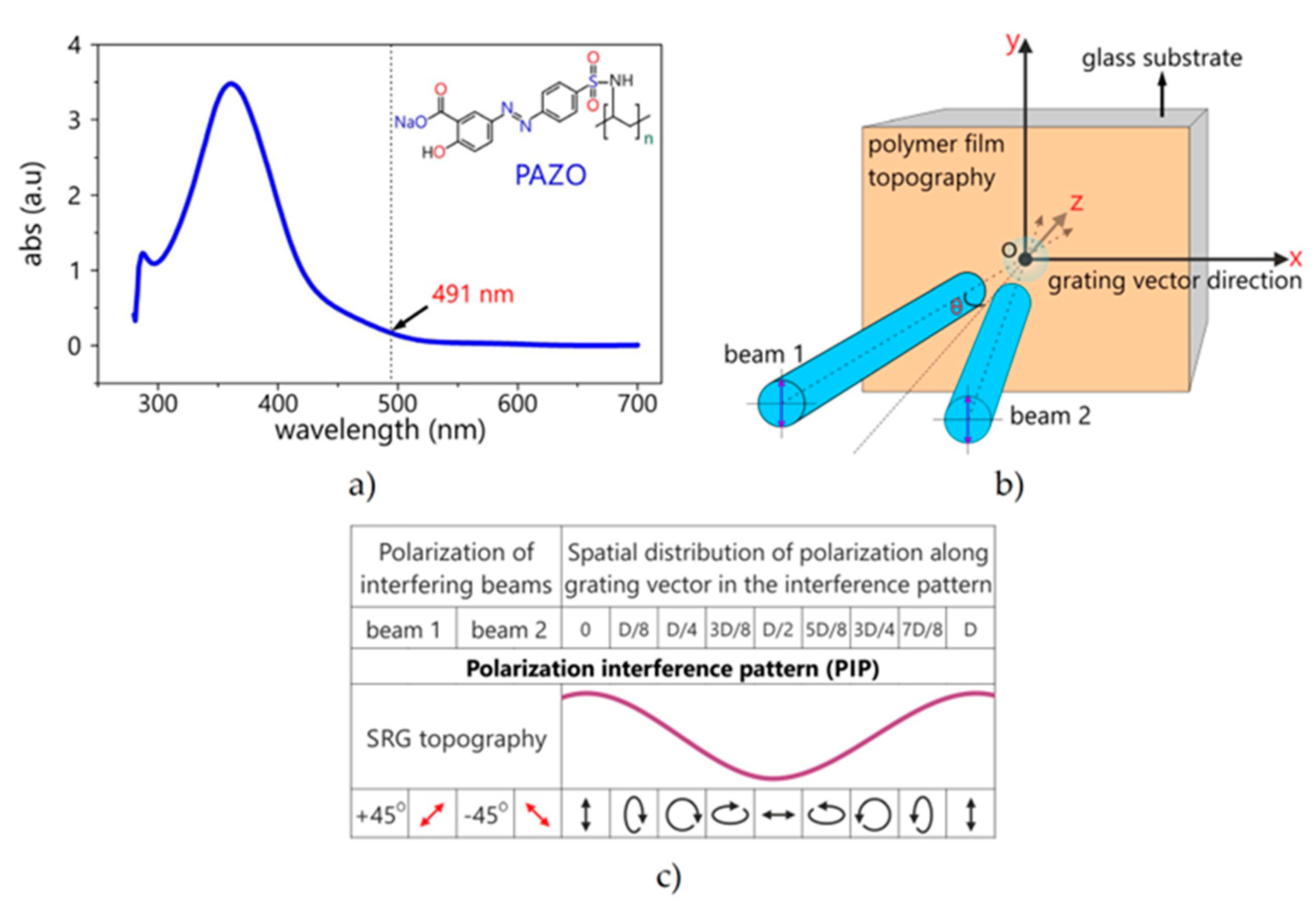
In our work, we use a polymer of high molecular weight with the azobenzene molecules covalently attached to it as the side chains PAZO (pol{1-[4–(3-carboxy-4-hydroxyphenylazo) benzenesulfonamido]-1,2-ethanediyl,sodiumsalt}). The chemical structure and absorption spectrum are presented in
Figure 1a. The samples were pieces of square glass (20 × 20 mm) with a thin layer of PAZO (1.1 μm) deposited by spin-coating technique.
The polymer surface was illuminated according to the technique described in [
25] using a ±45° polarization interference pattern. Thus, a round region with a light-induced periodic submicron relief was formed on the surface. The characteristics of the experimental samples with photo-induced relief are presented in
Table 1.
Figure 1c shows the interference pattern (±45°) used for inscription of the surface relief grating in the polymer films and the according distribution of the polarization of the electric field along the grating vector.
Figure 1b shows a diagram representing the principles of submicron relief formation in the interference area.
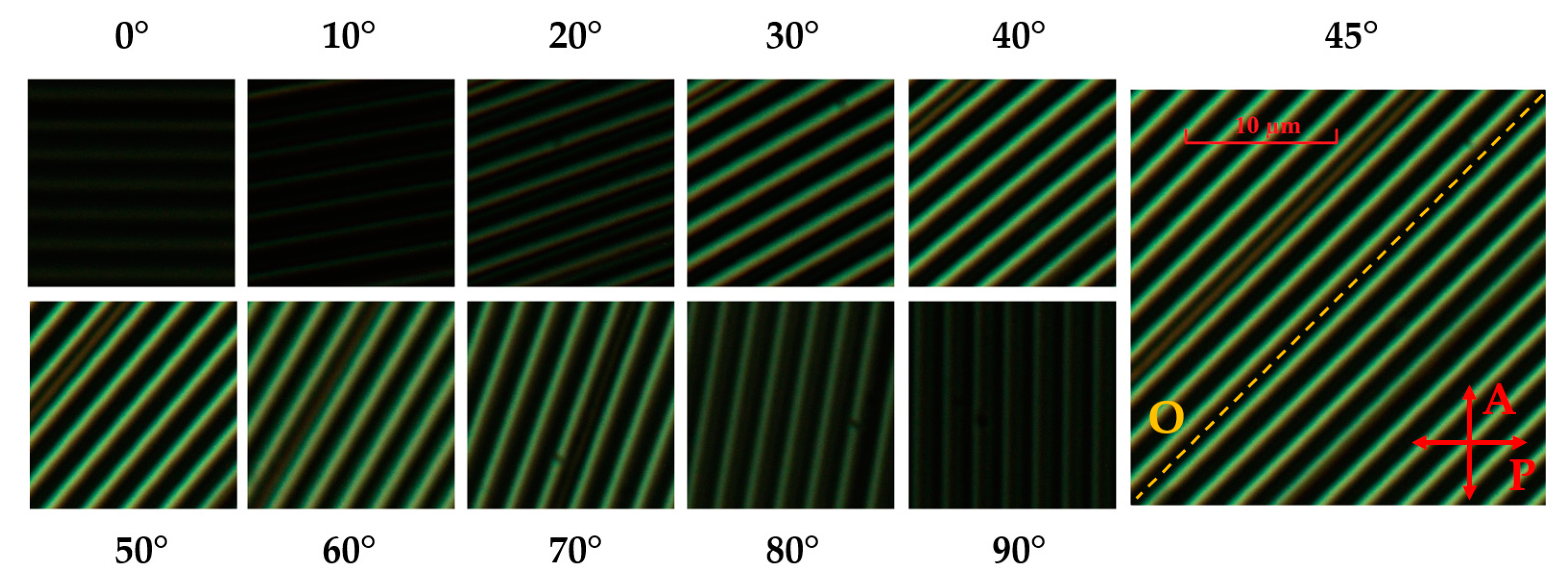
The technique described above leads to the formation of local opto-mechanical stress inside the polymer and deformation inside the layer, due to which the relief is formed. In order to determine the effect of this method of creating a relief on the optical properties of the polymer, the exposed samples were examined using the technique of polarization microscopy. The samples were placed between the crossed polarizer and the analyzer. In this case, the sample was initially oriented in the direction of the grooves along the direction of the polarizer transmission plane. The sample was then rotated counterclockwise. After that, the position of the relief relative to the polarizer and analyzer was determined, at which the maximum light transmission was observed.
Thus, it is shown in
Figure 2 that, after exposure, the PAZO polymer becomes optically anisotropic, and the optical axis becomes parallel to the direction of the grooves.
Previously [
20], it has been shown that the surface orientation of the LC was co-directional with the direction of the grooves when interacting with a relief formed by mechanical stamping (
l = 0.74 μm,
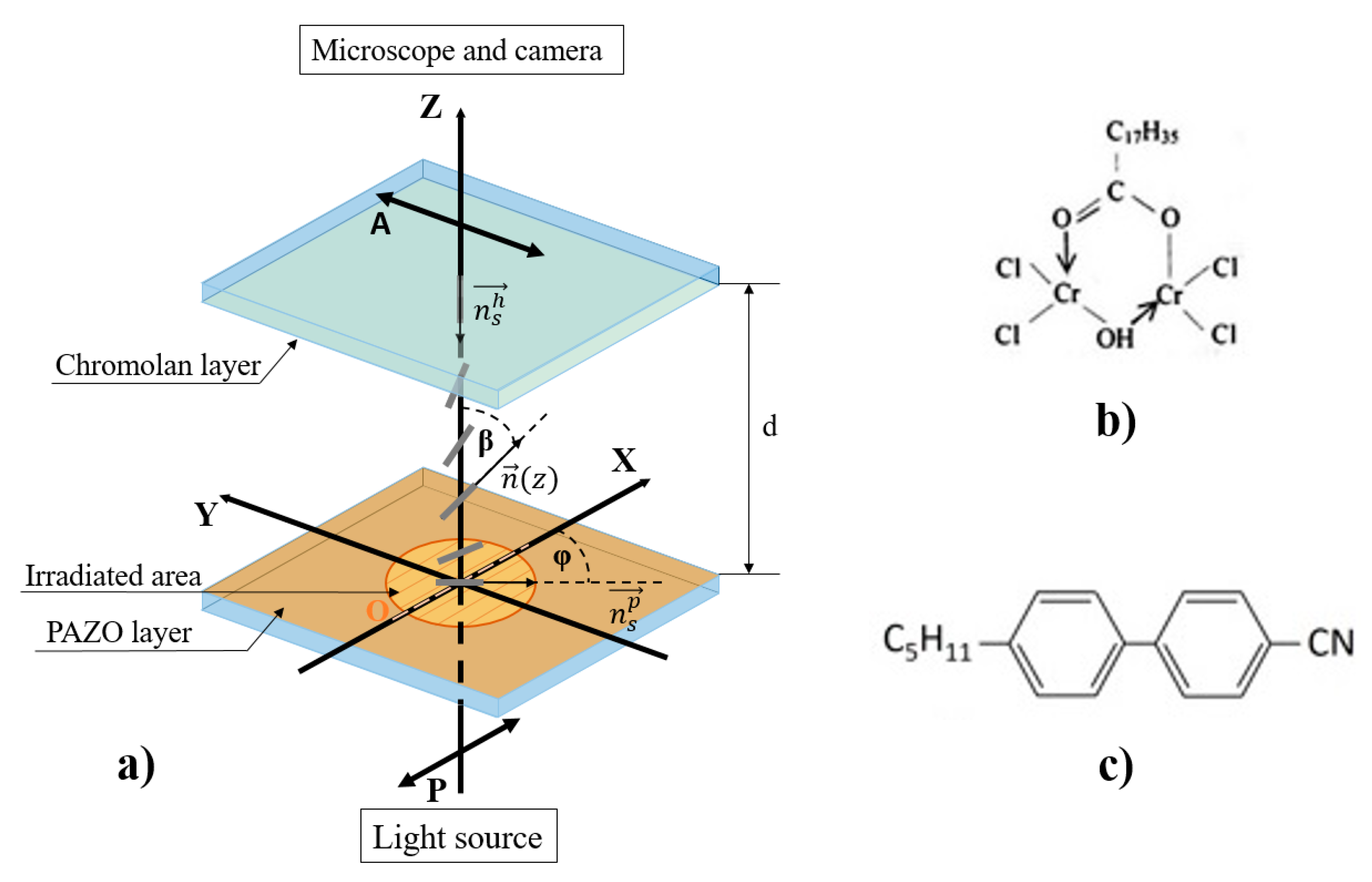
h = 0.15 μm). To check how the LC is oriented on the PAZO surface (both oriented and not), a simple sandwich-like cell was assembled. In this cell (
Figure 3a), on one of the surfaces there is a region with a photo-induced relief, and the other surface has a homeotropic surface orientation (the preferential direction of the long axes of the molecules—the director (
)—is oriented normally with the substrate surface). The gap between the pieces of glass was set by film spacers. The sealing and adjustment of the relative position of the plates was carried out using special clamps. The capillary gap was controlled by the spectrophotometric method.
The homeotropic orientation was created using 0.5% chromolane (chrome stearoyl chloride,
Figure 3b) solution in isopropanol, which was spin-coated onto the glass surface and then dried at 100 °C. After the cell was assembled, it was filled with nematic liquid crystal 5CB (4-cyano-4′-pentylbiphenyl,
Figure 3c) in the isotropic phase and slowly cooled. Thus, inhomogeneities, associated with the filling of the cell by LC, did not arise. Further studies were carried out at room temperature,
T = 23 ± 0.5 °C.
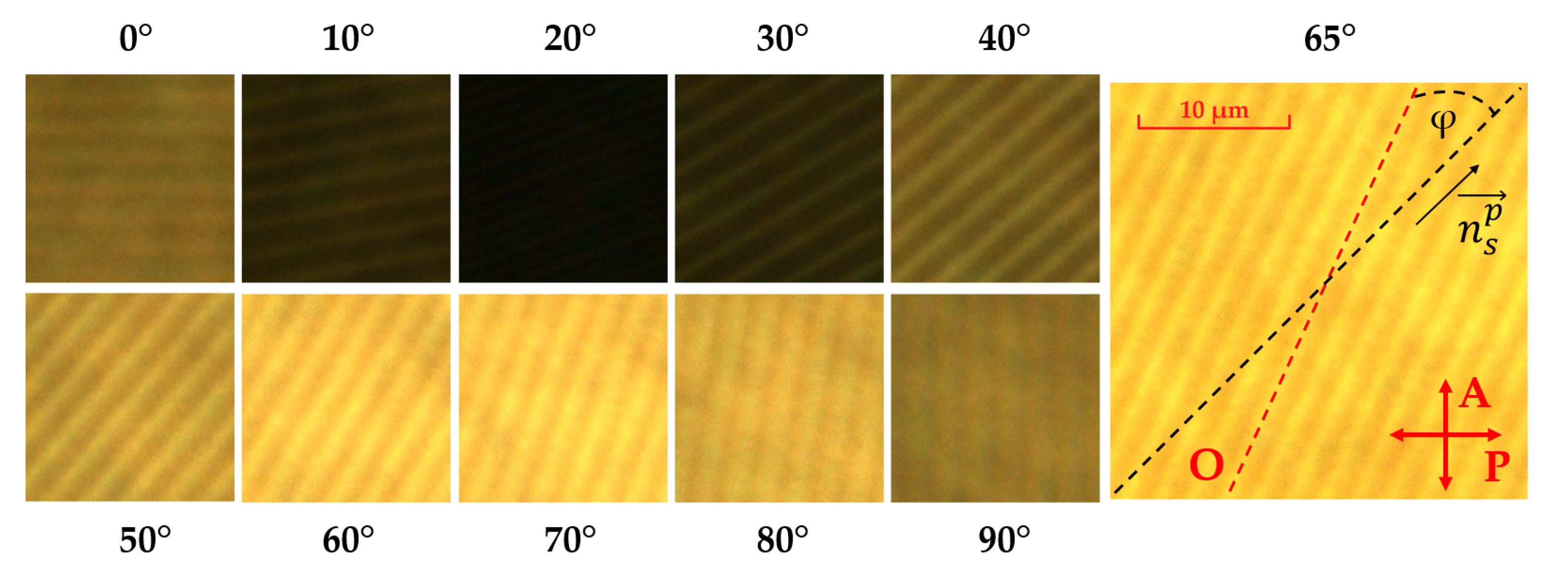
The polarization optical microscopy method described above was also used to determine the surface orientation of the LC on the irradiated PAZO and on the one that was not irradiated. The resulting images are shown in
Figure 4.
The presented images clearly show that the darkest image is observed when the cell is rotated by 20°, and the brightest image is observed when it is rotated by 65°. This indicates that the resulting orientation, , on the exposed PAZO surface is shifted at an angle φ ≈ 20° relative to the direction of the grooves. It becomes clear that, in addition to the orienting effect of the grooves, the orientation of the long polymer chains, which are capable of orienting LC, plays an important role.
To measure the anchoring strength of nematic 5CB at the photo-profiled polymer surface, we prepared wedge-like LC cells consisting of two glass plates (reference and tested plates). The reference glass plate was spin-coated with polyimide and rubbed to provide strong anchoring conditions. The tested plate was sample 2. The glass plates with corresponding polymer layers were aligned and sandwiched to provide coincidence of rubbing directions with grooves. A Mylar spacer placed between the glass plates along only one side of the LC cell formed a variable thickness of the LC cell, ranging from 2 to 5.5 μm. The assembled cell was filled with nematic 5CB in an isotropic phase and then slowly cooled to room temperature for DLS measurements.
The anchoring strength of the nematic 5CB on the photo-induced submicron relief surfaces was measured based on a dynamic light scattering technique [
30]. For this purpose, we used a photon correlation spectrometer Photocor Complex (LLC Photocor, Russia) to register the autocorrelation function of light intensity fluctuations. In this case, the LC cell was placed and kept in a thermostat of the spectrometer at a temperature of
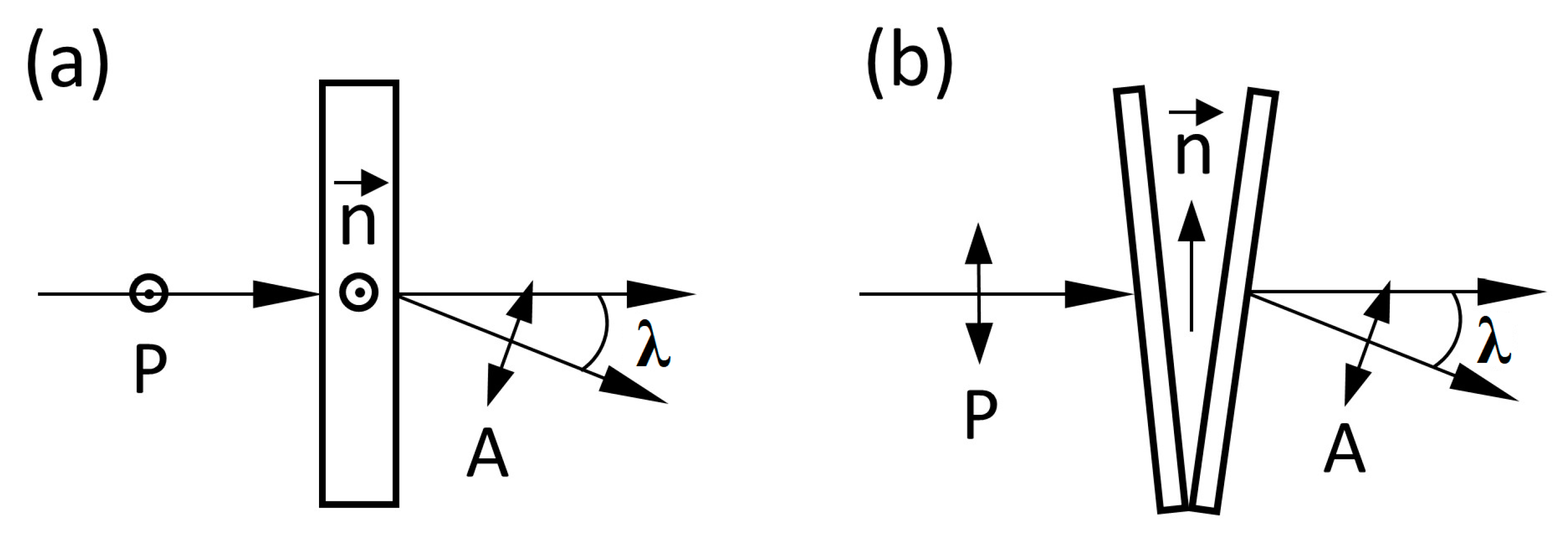
T = 26 °C for 2 h. After incubation, laser light, passing through the LC cell from the side of the reference substrate, was detected by a photomultiplier at a small light scattering angle, λ = 2°. Analysis of the autocorrelation functions was performed using Dyna LS software (LLC Photocor, Moscow, Russia), providing determination of relaxation time, τ, of the autocorrelation function corresponding to the relaxation time of the nematic director fluctuations. We registered autocorrelation function at different values of nematic thickness using two geometries (
Figure 5) allowing us to extract both the azimuthal and polar anchoring energies of 5CB at the photo-profiled polymer surfaces.
We measured the anchoring energy of nematic 5CB at the photo-profiled polymer surfaces using the dynamic light scattering method, which required no external fields acting on the LC.
Director fluctuations in a bulk NLC can be described by overdamped sinusoidal waves. In unlimited samples, two types of eigenmodes are present: the first one is a combination of splay and bend elastic deformations, and the second a combination of twist and bend deformations. For very thin samples (few microns) and small scattering angles (few degrees), the fundamental mode gives the dominant contribution to the scattered light. The relaxation time of the fundamental mode for infinitely strong anchoring conditions depends only on viscoelastic constants and the sample thickness of the LC [
30]:
where
γ is the rotational viscosity of LC,
d is the LC cell thickness, and
K is the nematic elastic module.
To describe strong finite or weak anchoring conditions, the extrapolation length is usually introduced, which is the ratio of the elastic constant to the anchoring strength, L = K/W, where W is the anchoring energy. For azimuthal anchoring, La = K22/Wa, and for polar, Lp = K11/Wp, where Wa (Wp) is the azimuthal (polar) anchoring strength and K22 (K11) is the twist (splay) LC elastic moduli.
In the case of strong (finite) anchoring, the extrapolation length is much smaller than the sample thickness (
L << d), and Equation (1) reads as:
For weak anchoring conditions, the extrapolation length,
L >> d, and the relaxation time of the fundamental mode can be written as:
Therefore, measuring the autocorrelation function using a photon correlation spectrometer, we derived the relaxation time, τ, and estimated the azimuthal/polar anchoring energy of 5CB at the photo-profiled polymer surfaces.
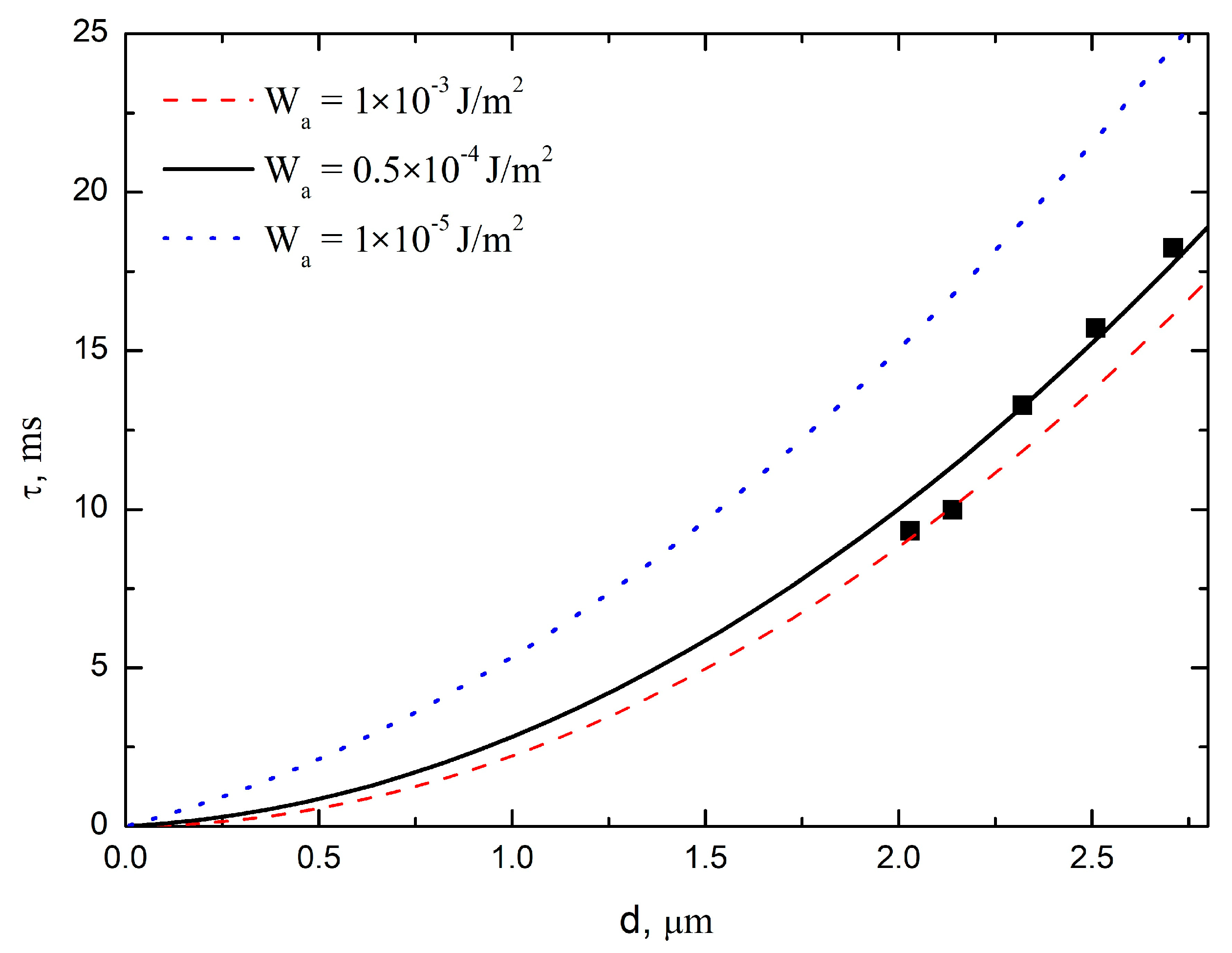
Figure 6 shows the experimental dependence of relaxation time,
τ, on nematic thickness, measured with the geometry depicted in
Figure 5a.
Previously reported results showed that two types of anchoring conditions yielded different dependencies of the relaxation time on sample thickness (linear dependence for weak, and quadratic dependence for strong anchoring) [
30].
Figure 6 shows a quadratic dependence of
τ(d), which indicates strong anchoring conditions. Fitting of the presented data using Equation (2) allowed estimation of the azimuthal anchoring strength in the range of 0.5 × 10
−4 J/m
2 …1 × 10
−3 J/m
2. This corresponds to a relatively strong azimuthal anchoring strength of nematic 5CB at submicron relief.
Figure 7 shows the dependence of relaxation time on nematic thickness, measured using the geometry shown in
Figure 5b.
Figure 7 shows that polar anchoring strength is in the range of 0.5 × 10
−4 J/m
2 … 1 × 10
−3 J/m
2, where best fitting took place at
Wp = 0.5 × 10
−4 J/m
2.
The presented data indicate that the photo-profiled PAZO film provides a strong azimuthal/polar anchoring strength of nematic 5CB, which is similar to traditional rubbed polymer aligning layers [
33].
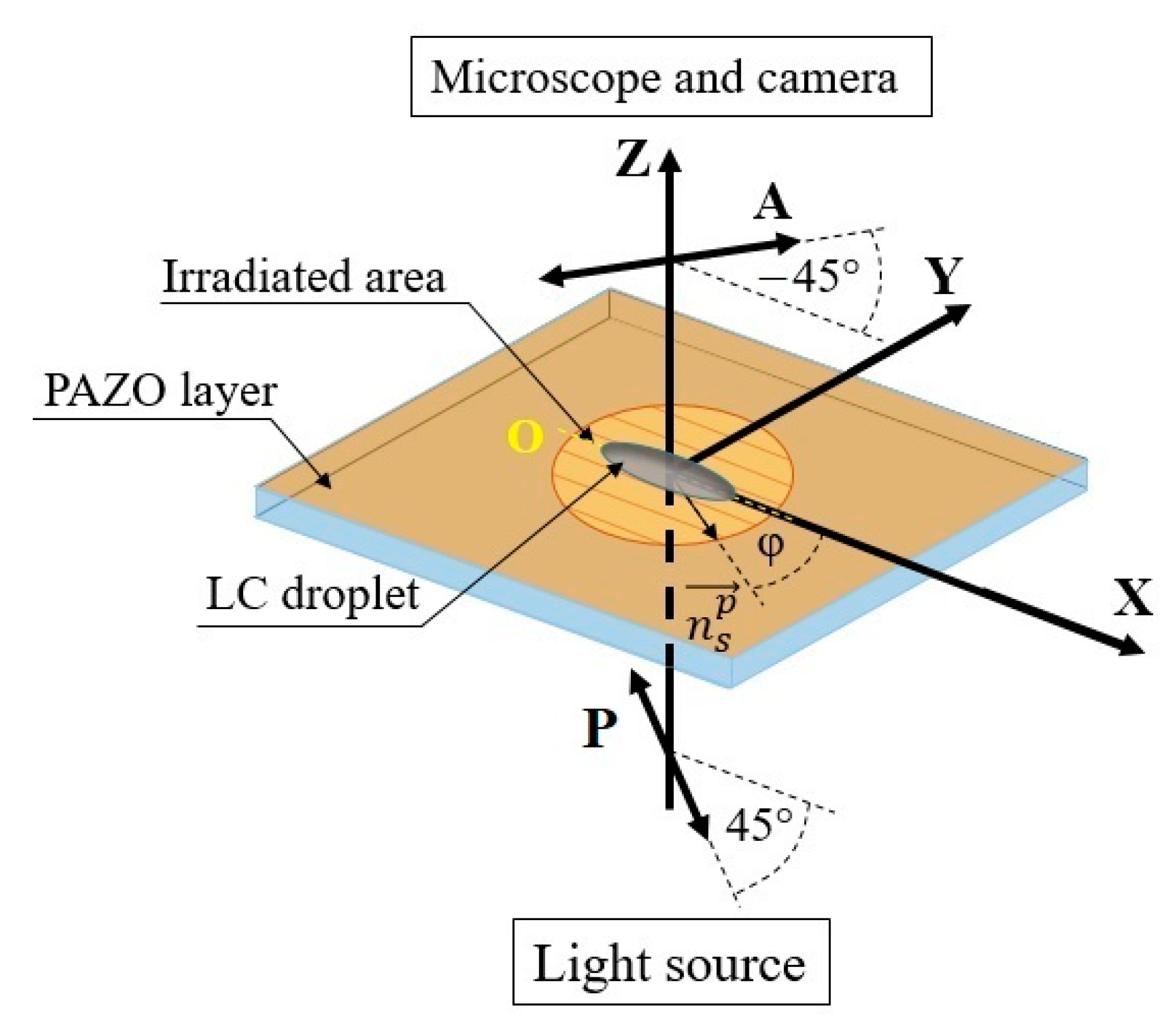
Investigation of the droplets’ spreading over the photo-profiled polymer surfaces was carried out with the help of the polarizing microscopy technique, similar to that used previously for registration of the spreading of LC droplets over the mechanically stamped submicron relief [
20].
Figure 8 shows a schematic representation of the position of the drop on the surface of the submicron relief. The sample was illuminated with monochromatic polarized light (semiconductor laser,
λ = 650 nm), which provided more correct calculations of the local thickness of the LC layer in comparison with the use of white light [
20]. The crossed polarizers were oriented at an angle 45°, relative to the direction of the submicron relief. The droplets of 5CB with an initial diameter of less than 1 mm were deposited on the submicron relief surface with a micropipette. The microscopic images of the spreading droplets were registered by a digital video camera. Studies were carried out at room temperature,
T = 23 ± 0.5 °C.
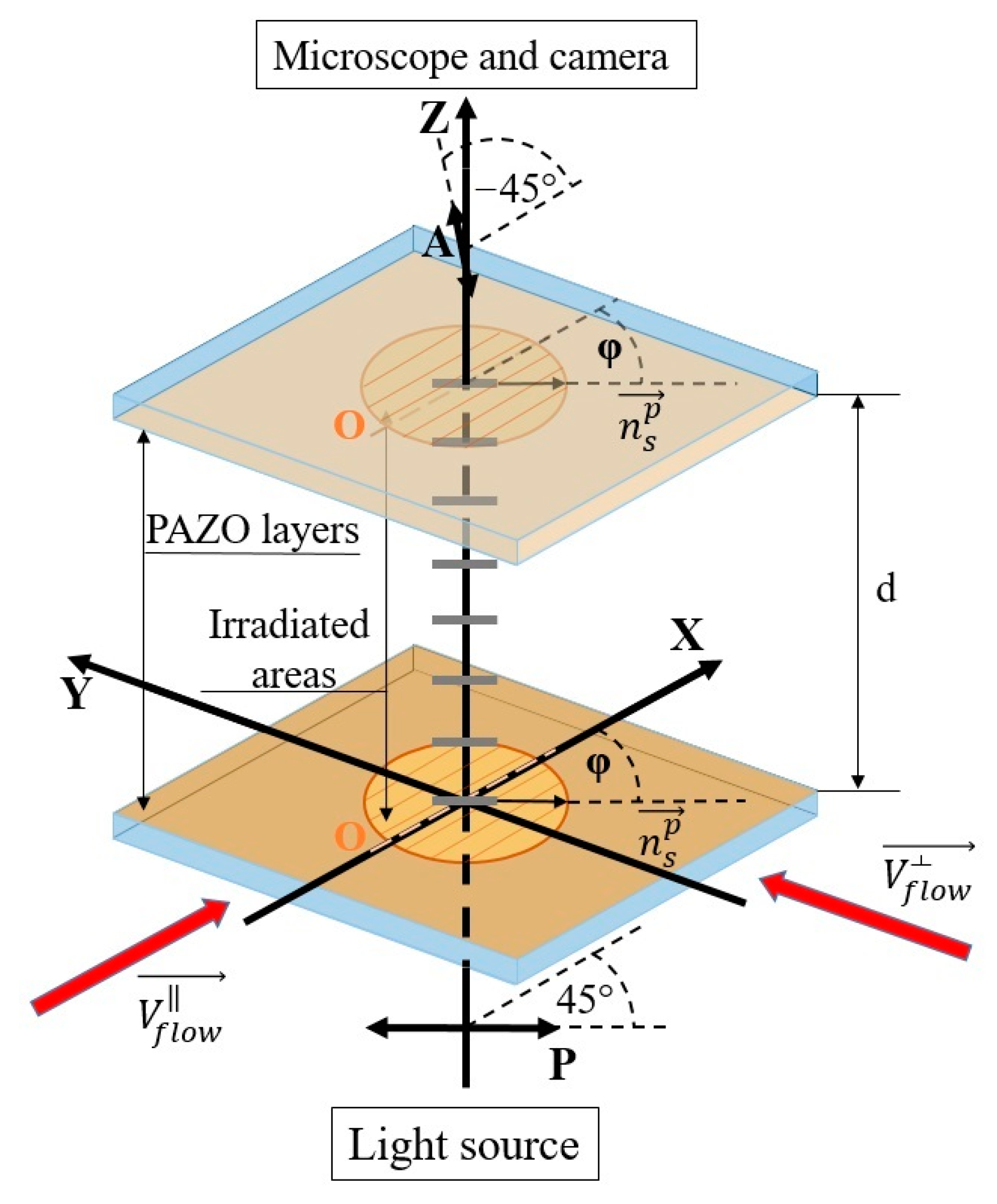
In experiments with a capillary shear flow in a plane capillary, the cells with a construction similar to that shown in
Figure 3a were used. The main difference is the use of the photo-profiled inner surfaces on both substrates with the single direction of a relief, as shown in
Figure 9.
The design feature of the cell provided measurements of the effective viscosity of LC at different values of the capillary gap at different orientations (parallel and perpendicular) of the flow direction relative to the direction of the submicron relief. The cell was formed by two flat glass plates with a submicron relief of the same height and period (samples 3 and 4), the gap between them was set by film spacers. The sealing and adjustment of the relative position of the plates was carried out using special clamps. The capillary gap was controlled by the spectrophotometric method at the edges of the capillary and in areas close to the illuminated area.
The scheme of the experiment is similar to that described in [
34]; the main difference is that the capillary consists of three regions: a region without a relief at the beginning, a region with a relief, and a region without a relief at the end. Thus, it was possible to observe the movement of the contact line under the action of capillary forces in the cell, where the relief was oriented along flow direction (
) and across flow direction (
).
The capillary flow arose after a portion of the LC was brought into contact with the open edge of the capillary. The instantaneous polarizing images of the cell with the moving meniscus were recorded by a digital camera. The processing of such images was used to study the dynamics of a capillary flow of an LC interacting with the anisotropic photo-profiled surfaces. All experiments were carried out at room temperature, T = 23 ± 0.5 °C.
3. Results and Discussion
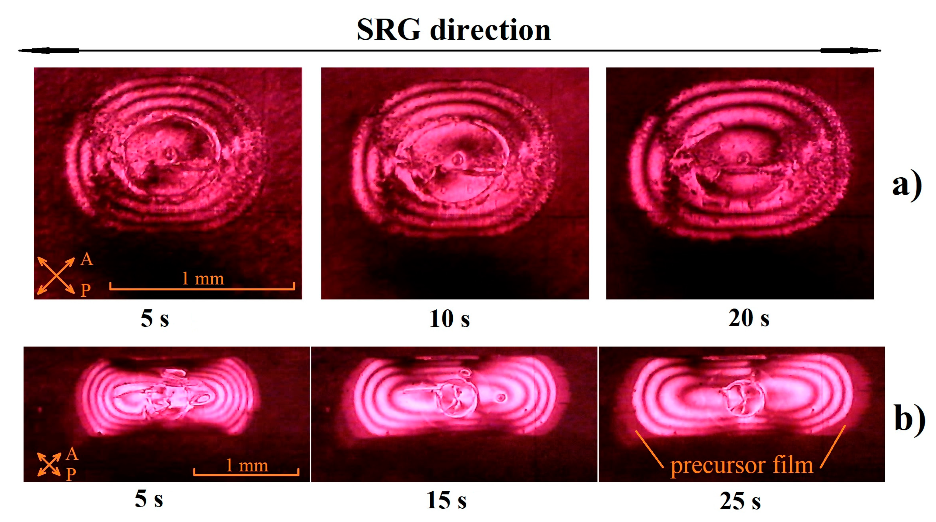
The examples of the instant interference images of the droplets for the two experimental cells, with essentially different heights of the submicron relief, are shown in
Figure 10. The analysis of the obtained images provided calculation of the local thickness of the LC layer in the vicinity of a contact line.
In order to determine the local thickness (
d) in an LC drop, we took into account the dynamic correlation spectroscopy results presented above, which confirmed a rather strong planar anchoring of LC with the photo-induced relief. Similar to the assumption used in [
20], the homeotropic orientation is assigned to the air–LC interface (
Figure 11). For such a homeoplanar orientation of LC, the simple expression for the polar angle,
β, as a function of the
z coordinate can be obtained using one constant approximation,
K11 ≈
K33 =
K (
Kii (
i = 1…3) is the Frank elastic constants):
The non-zero values of the polar angle result in a phase difference, Φ, between extraordinary (e) and ordinary (o) rays:
where
; the local difference between the extraordinary
n(
β) and ordinary (
n0) refractive indexes, with
n(
β) expressed as:
where
ne is the maximal value of the extraordinary refractive index.
In the case of a relatively weak optical anisotropy,
, one can obtain the next expression for the phase difference:
The intensity,
I, of polarized light passed through the LC layer can be expressed as:
where
I0 is the intensity of the input light. The presented expressions, (7) and (8), make it possible to restore the instant profiles of a droplet via the analysis of light intensity distribution in the interference pictures, as shown in
Figure 10. In particular, the values of the local thickness of LC film, corresponding to interference maxima or minima of the interference pictures, are expressed by Equation (7) or Equation (8):
where
k is the number of the extremum. The examples of the instant profiles of the spreading droplet are shown in
Figure 11b. The extrapolation of the curves, describing such profiles to the intersection with the surface of the polymer layer, provides determination of the position of a contact line as well as the instant value of a contact angle.
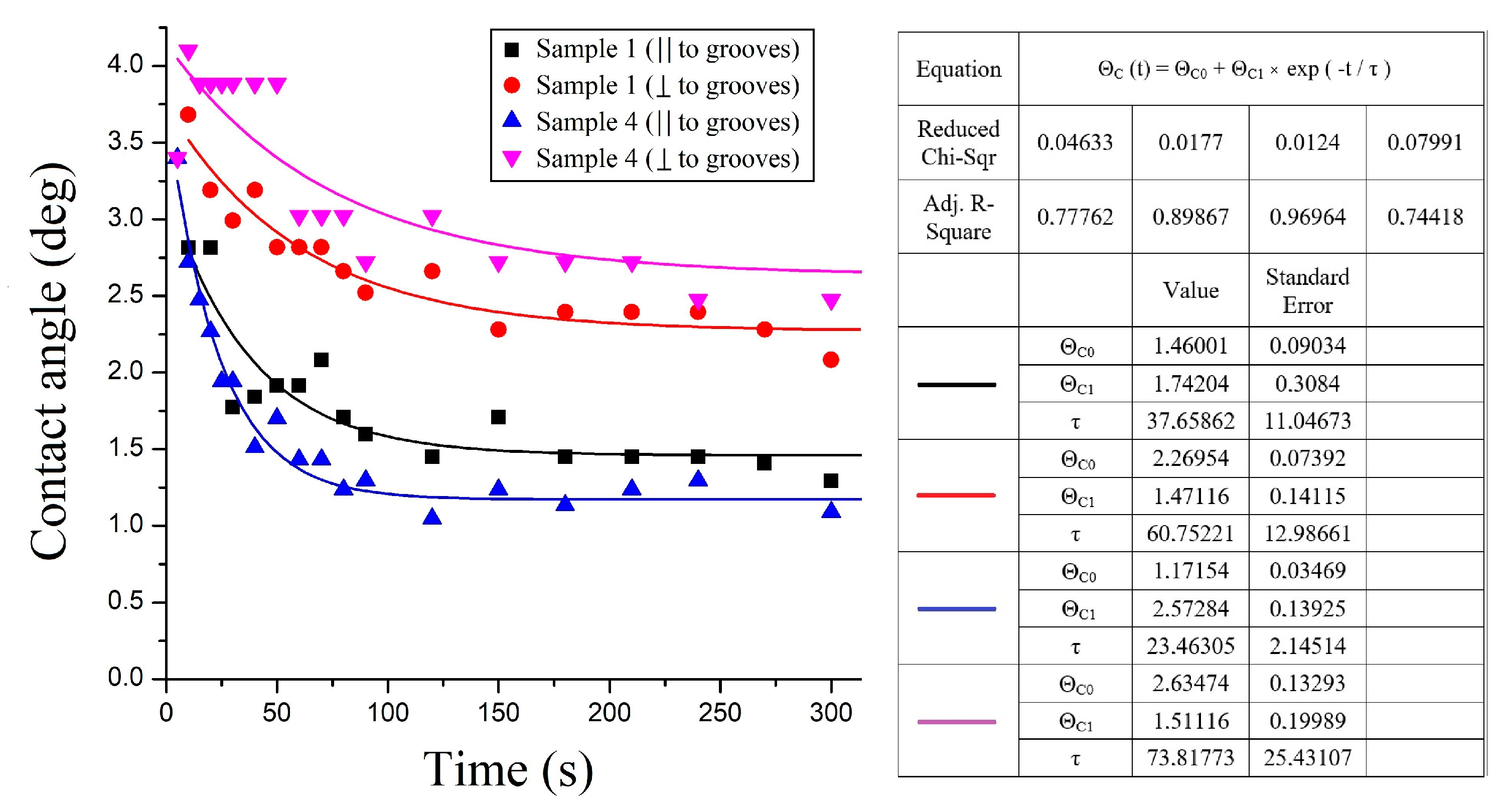
The dependences of the contact angle on time at two principal orientations of the flow velocity relatively to the direction of a relief (parallel and perpendicular to the groves) for the samples with the different values of the height of a relief are shown in
Figure 12. One can observe the relatively fast decreasing of the contact angle at the initial stage of spreading, slowly approaching to the stationary value at the final stage. The range of variation of this parameter with time from 3.0° to 1.5° in the direction of spreading parallel to the grooves is close to the range (from 5.0° to 2.2°) obtained at similar experiments with the spreading of an LC droplet over a mechanically stamped relief with the close value (approximately 150 nm) of the relief height. Comparison between the results obtained for different samples reveals the essential increase in the anisotropy of the dynamical contact angle with the increase in the height of a relief (see
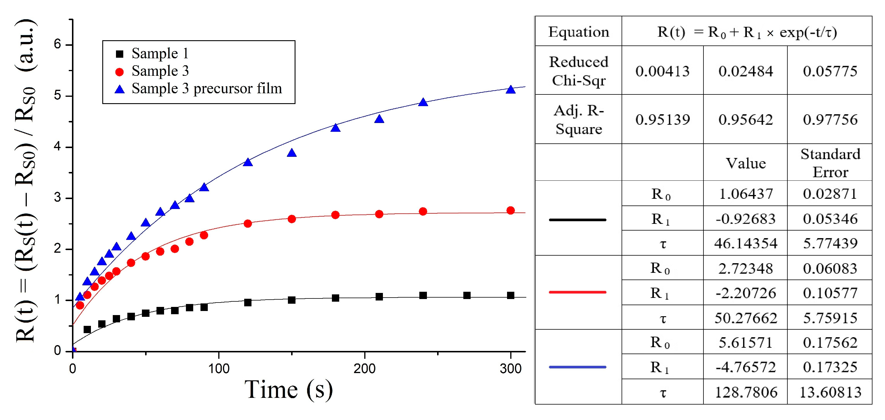
Figure 12). It is worth noting that the character of motion of the precursor line also strongly depends on the height of the relief. In particular, in the comparison with the relatively large distant between the positions of a contact and precursor lines, observed at spreading along the relief with large height, this distance is essentially lower at the spreading of the LC droplet over a relief with the smaller height, and in the photographs it almost does not differ from the movement of the contact line.
In the case of an LC drop spreading over the surface of a sample with a lower relief height (sample 1), the contact line moved in a direction perpendicular to the direction of the grooves only at the very beginning of spreading (the first few seconds), while for samples with a sufficiently large relief height (sample 3), spreading in the direction normal to the relief direction was not observed at all.
Figure 13 shows normalized to the initial droplet size time dependences of the displacement of the contact and precursor lines along the direction of the relief for samples 1 and 3.
A similar experiment on the spreading of an LC drop over the surface of an unexposed PAZO showed that the drop spreads as though it were an isotropic surface and does not have a preferred spreading direction. At the same time, interference fringes are observed in crossed polarizers along the direction of the analyzer and polarizer transmission planes, which makes it possible to similarly estimate the contact angle at the LC–PAZO interface. In our case, it turned out to be equal to 20° at the beginning of spreading and 15° at the end of spreading.
Using Equations (7) and (8), as well as digital image processing, the local thickness of the precursor film was determined using the ratio of the light intensities in the region of the precursor film and the region of maximum of interference. The value of the local thickness in the precursor film was equal to 1 µm near the main mass of the drop and 0.4 µm at the boundary of the precursor.
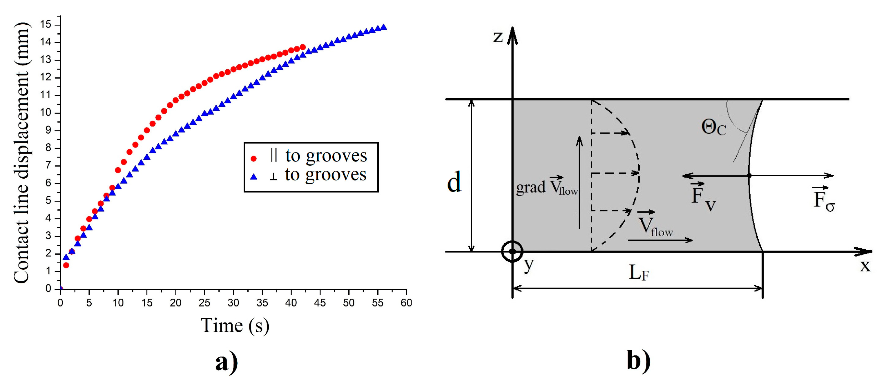
The results of the investigation of the dynamics of the capillary flow in plane capillaries were also obtained due to the processing of instant photos. The examples of such photos, taken at the usage of white polarized light, are presented in
Figure 14. The motion of the meniscus is well visualized, which makes it possible to determine the displacement of a contact line with time. The corresponding results for two orthogonal orientations of the capillary flow relative to the direction of a relief are shown in
Figure 15. The wide interference lines on the image can be assigned to the weak space variations of the thickness of the LC layer contacted with the relief surface. At the same time, there is no evidence of flow-induced changes of the initial orientation. This means that the photo-induced relief can be used for stabilization of LC orientation, which is important for shear viscosity measurements.
Therefore, when processing the data on the capillary flow in a cell with two photo-induced substrates (
Figure 14), we assumed, similarly to [
34], that LC is a conventional Newtonian liquid with a constant value of the shear viscosity coefficient (
η), which depends on the director’s orientation respective to the flow velocity direction and velocity gradient.
We also considered the contact angle as a constant value, which is time-independent. It holds at small values of the capillary number [
21]:
where
v =
dl/
dt is the velocity of the contact line and
σ is the surface tension coefficient.
Using the values
σ = 0.03 N/m and
η = 0.1 Pa s (maximal at corresponding temperature) for a 5CB liquid crystal [
10] and obtained value of
v < 10 mm/s at the initial stage of capillary flow, we obtain capillary number Ca = 0.003, which allows us to consider the contact angle as a constant.
The above-mentioned approximations make it possible to describe the displacement of the contact line in a horizontally oriented capillary. The pressure balance expression obtained by taking into account only the capillary (
Fσ) and the viscous (
Fv) forces, acting on the sample of LC (
Figure 15b), can be written as:
where
is the capillary pressure, and
is the pressure drop caused by viscosity losses during the laminar flow of a liquid through the plane capillary;
η is the shear viscosity of a liquid. This expression is derived with the help of the formula
Q =
dV/
dt, describing the volumetric flow rate of liquid during a steady Poiseuille flow through a capillary with a gap d, width
A, and length
L:
By inserting (13) and (14) into expression (12), it is simple to obtain the next differential equation for
LF(
t):
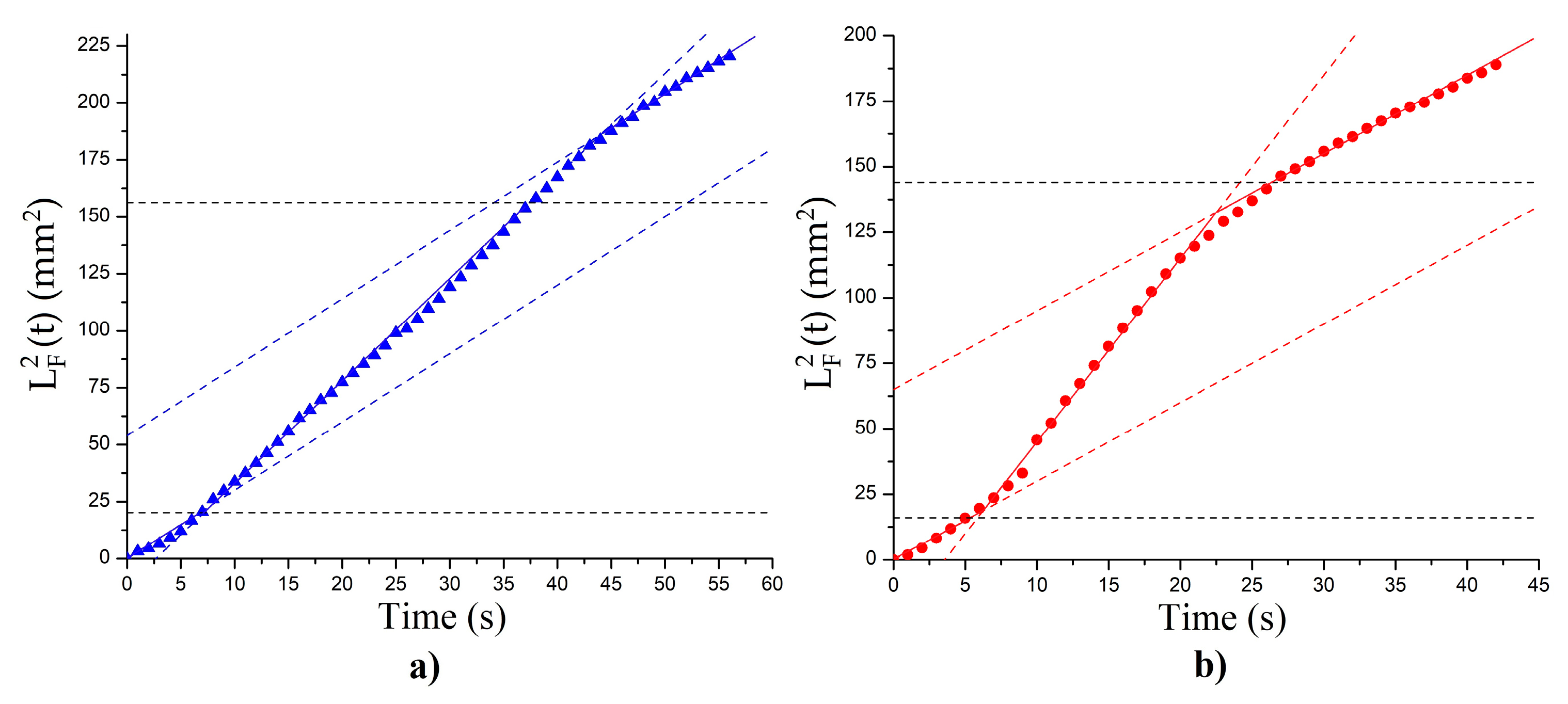
The solution of Equation (15) leads to the linear dependence of
on time, written as:
As can be seen in
Figure 16, three sections can be considered (the area before the relief, the area with the relief, the area after the relief). The corresponding values of the effective viscosity are 0.051 ± 0.004 Pa·s for the untreated areas before and after the relief (
Figure 16a,b). For the area with relief in the case when flow direction was parallel to the grooves orientation, the value of shear viscosity was equal to 0.024 ± 0.002 Pa·s (
Figure 16b). This is close to the minimum Miesowicz viscosity for the given temperature of the experiment (
η2 = 0.023 Pa·s [
10]) for the case when the director is oriented along the flow. For the case when the flow is directed perpendicular to the direction of the relief (
Figure 15a), an effective shear viscosity in the area with relief was 0.037 ± 0.002 Pa·s, which is close to the Miesowicz viscosity
η3 = 0.033 Pa·s, corresponding to the orientation of the director perpendicular to the flow plane. Thus, at small thicknesses of the LC layer, the surface stabilizes the orientational structure of the liquid crystal, which makes it possible to use the capillaries with photo-profiled surfaces at the experimental determination of anisotropic shear viscosities of liquid crystals.
Finally, we have to point out that, in spite of the general nature of the two types of capillary flow described above, they also demonstrate differences in dynamics. In particular, simple time dependence (17) for a contact line motion in plane capillaries does not hold for the anisotropic spreading of LC droplets. This may be connected with the different roles of free surfaces in the phenomenon, as mentioned above. In particular, the changes in the area of the free surface inside a capillary are connected only with the dynamic changes of the contact angle and can be neglected in our case. At the same time, such changes can essentially exceed the initial area of the free surface of the spherical droplet placed on the surface. This means that variation of the free surface area with time plays a key role in droplet spreading. Additionally, the influence of changes in the gravity energy of a droplet, taking place at spreading, also modifies the dynamics of spreading. The detailed analysis of anisotropic motion of the precursor line, registered in our experiments, demands the use of a mesoscopic or microscopic theoretical description. In particular, the performed molecular dynamical simulation of the kinetics of spreading of isotropic nano-droplets over submicron relief surfaces of different topologies [
35] made it possible to determine the time dependence of the precursor film displacement, similar to that shown in
Figure 15. We hope that the presented experimental results will also stimulate microscopic theoretical investigations for the spreading of LC droplets.
