Article

Design of MIMO Antenna with Double L-Shaped Structure for 5G NR

1
School of Electrical and Information Engineering, Anhui University of Science and Technology, Huainan 232001, China
2
School of Electrical and Communications Engineering, West Anhui University, Lu’an, 237012, China
3
School of Mechanical and Electrical Engineering, Huainan Normal University, Huainan 232001, China
*
Author to whom correspondence should be addressed.
Symmetry 2023, 15(3), 579; https://doi.org/10.3390/sym15030579
Submission received: 31 January 2023 / Revised: 18 February 2023 / Accepted: 21 February 2023 / Published: 23 February 2023
(This article belongs to the Special Issue Recent Advances in Antenna Array Technologies)

Abstract

:
To satisfy the demand for 5G communication to smartphone terminal antennas in element quantity and isolation, an eight-element wideband MIMO antenna set of high isolation level is proposed. Each antenna element in the array is a double-L antenna consisting of an L-shaped slot and an L-shaped 50 Ω microstrip line. The L slot is formed by adding an I-shaped open circuit directly to the side of the rectangular slot. In addition, the antenna arrays are located on the long bezels on both sides of the mobile phone motherboard, and the coupling feed is made in the frequency range of 3.6–4.7 GHz through the L-shaped microstrip line, so as to cover the 5G NR band (N77/N78/N79). Finally, the four element pairs (8 components) achieve isolation of greater than 11 dB, the performance frequency range is 3.6–4.7GHz, the return loss is −6 dB, the total efficiency is greater than 85%, and the envelope correlation coefficient is less than 0.08. Other MIMO performances are also calculated, the design process is discussed in detail, and one-handed grip mode and two-handed grip mode are discussed to demonstrate their stabilities in real-world applications.

1. Introduction

Because of the rapid advancement of science and technology, mobile communication has evolved from the 2G era to the 3G and 4G eras and is now gradually shifting to the new 5G era [1]. The prime focus of the research and development on 5G mobile terminal communication technology is to meet the needs of high-speed data transmission, low latency, ultra-high bandwidth, ultra-high capacity, and backward compatibility. The theoretical transmission speed of 5G mobile communication can reach up to 10 Gbps. High-speed transmission can provide fast data processing, high reliability, and paves the way for IoT (Internet of Things) big data transmission. Likewise, the fifth-generation New Radio (5G NR) communication system, the global 5G standard based on the new OFDM (Orthogonal Frequency Division Multiplexing) air interface design, 5G technology will achieve ultra-low latency and high reliability, which are an important foundation for the next generation of mobile technology. From the perspective of the development trend of 5G networks in recent years, 5G NR systems working in the N77/N78/N79 frequency bands will be widely used in mobile communications [2].
According to communication system theory, the larger the channel capacity, the higher the data transmission rate. In this regard, there are two main ways to improve the channel capacity: increase the channel bandwidth or increase the number of antenna systems. Since the channel bandwidth in a wireless communication system is often limited by the size of the carrier frequency, and the transmission power of the antenna cannot be increased easily, we mainly focus on the latter method for improving the channel capacity and use the MIMO antenna technology as the basis for our design [1]. Fundamentally, MIMO technology corresponds to an antenna unit that simultaneously receives the transmitted signal, and in MIMO systems, the multipath effect of the wireless communication system is used to increase the channel capacity, so that the transmission rate of the antenna can be improved. In addition, slot antennas, which are widely used in communication, need to be slit in the conductor surface because they have a low figure of merit and wide impedance bandwidth, and this paper is based on slot antennas.
Recently, several studies on MIMO antennas utilized in 5G NR (New Radio) operation bands have been done [3,4,5,6,7,8,9,10,11,12,13,14,15,16,17,18,19,20,21,22,23,24]. These studies proposed a number of antenna design methods, including the planar inverted-F antenna (PIFA), loop, monopole antenna, and inverted-F. In [2], we examined the two-antenna building block design consisting of a gap-coupled loop antenna and a loop antenna to improve isolation. The complex electromagnet environment made it such that the stronger the mutual coupling between the antennas, the greater the correlation and the worse the antenna radiation performance [25,26]. Therefore, under the premise of ensuring a good antenna radiation performance, decoupling of multi-band antenna arrays and antenna miniaturization to improve the compatibility with smartphones have become the next problems to be solved.
In view of the above discussion, this paper proposes a broadband eight-port slot antenna with high isolation suitable for 5G NR. Briefly, the antennas are designed using the approach of slotting the metal plate. In order to achieve broadband coverage with the impedance matching characteristics of the antenna, an open branch is added to one side of the rectangular slot to form an L-shaped slot. Furthermore, the L-shaped branch covering the 5G NR bands employs a coupled feeding scheme. The improved slot antenna has an ECC of less than 0.08 and a bandwidth of 3.6 GHz to 4.7 GHz.
The remainder of this paper is structured as follows. Section 2 discusses the design process and working mechanism of the MIMO system. In Section 3, the fabrication of the proposed MIMO antenna system and the corresponding simulated and measured performance results are presented. A comparison table is also included to highlight the advantages of the suggested design. Antenna performance in hand-held situations, including single-handset mode (SHM) and dual-handset mode (DHM), is covered in Section 4. Finally, Section 5 draws conclusions about this paper.

2. Design of Proposed MIMO Antenna

2.1. Antenna Geometry

The proposed eight-port MIMO antenna is shown in Figure 1a, and it has eight antenna units with numbers ranging from Ant1 to Ant8. On an FR4 substrate with copper cladding on both sides and a relative permittivity of 4.4, these antenna elements are arranged symmetrically. The size of the substrate used in this design is 150 × 75 × 0.8 mm3. Meanwhile, the dimensions of the proposed antenna are L1 = 4 mm, L2 = 10.9 mm, W1 = 2.5 mm, and W2 = 1 mm, as shown in Figure 1, indicating that the antenna can be easily used in a 5.9-inch 5G smartphone. Figure 1b shows the detailed structure of the antenna elements (taking Ant1 as an example). A feed strip printed in the shape of an L is used to feed the slot coupling. The feeding strip is divided into two sections, namely the vertical part with dimensions 13.4 × 2.5 mm2 (50 Ω feeders) and the horizontal stub with dimensions of 4 × 2.5 mm2. This antenna, unlike traditional closed-slot antennas, has an etched L-slot radiator with an open slot. The slot is divided into two parts in this case: horizontal slot and open branch slot. The horizontal slot’s length and width are 9 mm and 5 mm, respectively, on which the I-shaped open branch is etched. Furthermore, the open branch’s size is 4 mm 1 mm, and this extended open branch is used to increase the capacitance of the slot antenna, thereby improving the antenna’s impedance matching performance.

2.2. Design and Analysis

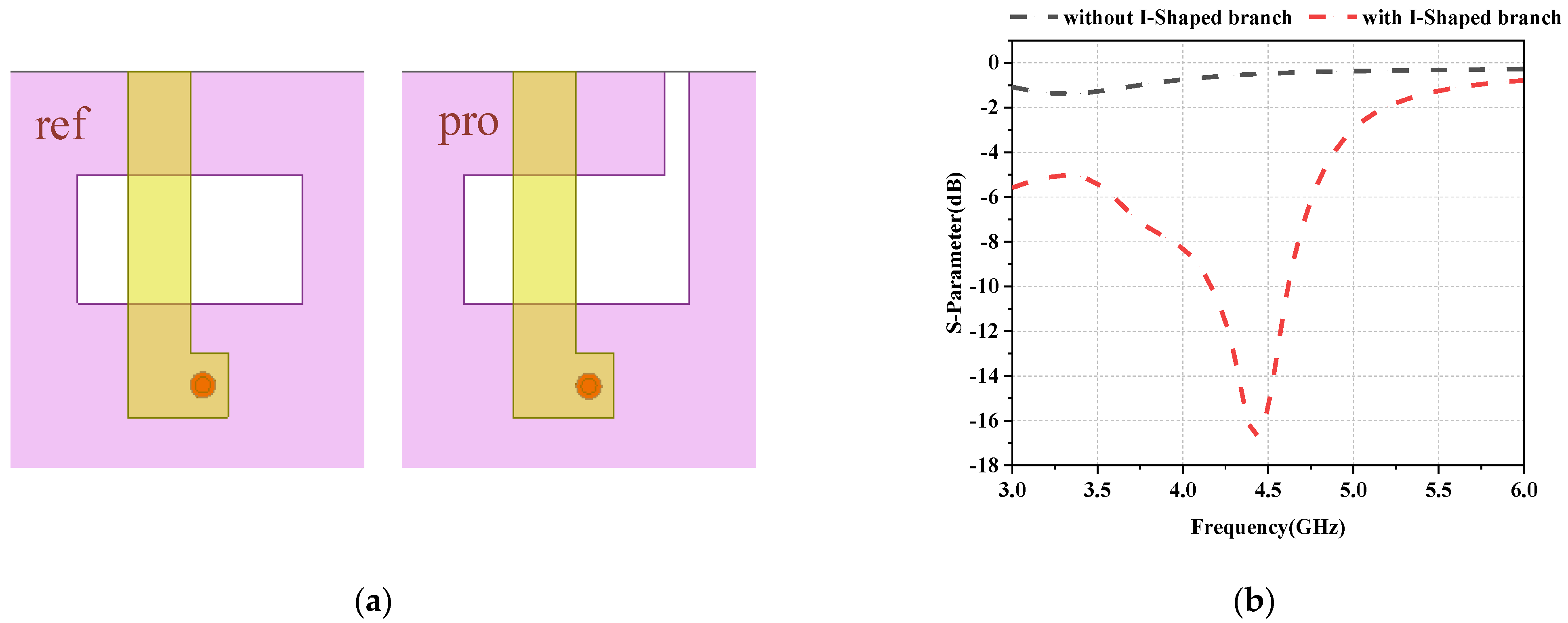
A rectangular slot is a popular antenna construction, however, unlike most other elongated rectangular slots, the width of the proposed rectangular slot is approximately 55% of its length. To verify the effect of adding an open branch on antenna capacitance, the comparison of the proposed L-slot to the rectangular slot is shown in Figure 2. When these two antenna elements are placed in the upper left corner (at the position of Ant1), the performance of the antenna elements is significantly different. As shown in Figure 2b, the impedance matching performance of the reference antenna element is extremely low. While in contrast, the proposed antenna element generates resonant modes at 4.4 GHz through the utility of an I-shaped open branch on one side of a rectangular slot, which exhibits superior impedance matching properties. It can be concluded that the addition of open circuit branches can increase the capacitance of the antenna, so the impedance matching performance of the antenna can achieve broadband coverage.

2.3. Current Distribution

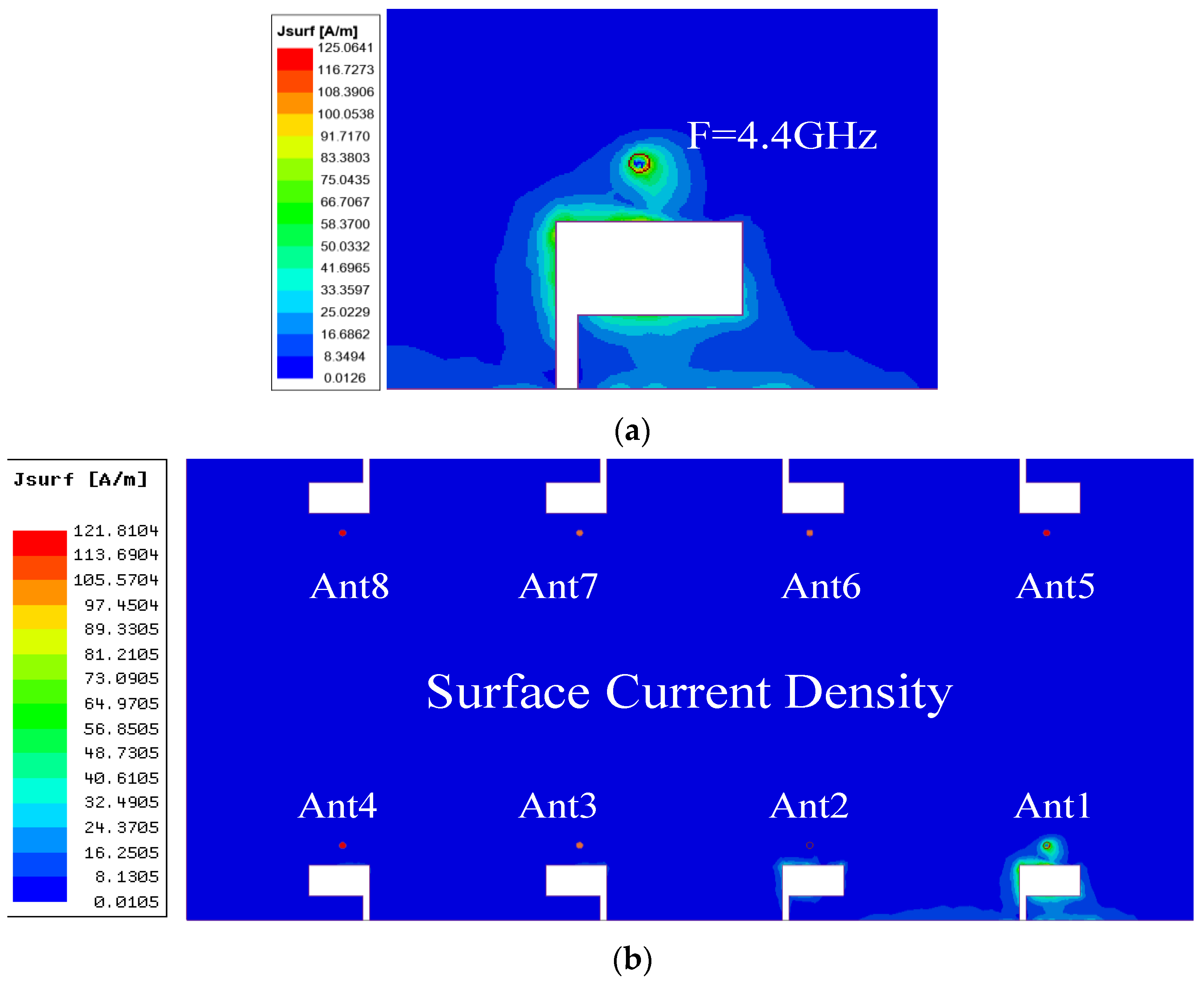
In MIMO antenna designs, antenna elements are usually placed farther away from each other, or decoupling structures are introduced, to avoid the inter-element coupling. Alternatively, a low coupling effect is achieved in the proposed MIMO design by simply yet rationally adjusting the layout of antenna elements to mitigate the need for additional decoupling structure. Figure 3 shows the current distribution of Ant1 when excited at 4.4 GHz, and the current distribution on the ground of the antenna visually illustrates the coupling effect between the antennas. The half side of the T-shaped slot, which has a length of 11 mm and is nearly one-third of the 4.4 GHz wavelength, is where the strong current is concentrated when the slot antenna runs at 4.4 GHz. This shows that the antenna functions in 0.33 resonant mode at 4.4 GHz (corresponding to 4.4 GHz wavelength). When one antenna element is activated, the current does not propagate to the surrounding antenna elements, according to the illustration. Essentially, the coupling between the antenna elements is reduced. In this design, by reducing the size of individual antenna elements, the distance between the antennas is increased, yielding high isolation.

3. Results and Discussion

Figure 4 depicts a fabricated prototype of the eight-element MIMO antenna system. To validate its effectiveness, the proposed design was simulated, fabricated, and tested. The simulations were performed using HFSS version 18, and the S-parameters of the fabricated prototype were measured using an Agilent Network Analyzer. Furthermore, the overall efficiency and radiation characteristics of the constructed system were evaluated in a microwave-shielded anechoic chamber.

3.1. S-Parameters and Antenna Efficiency

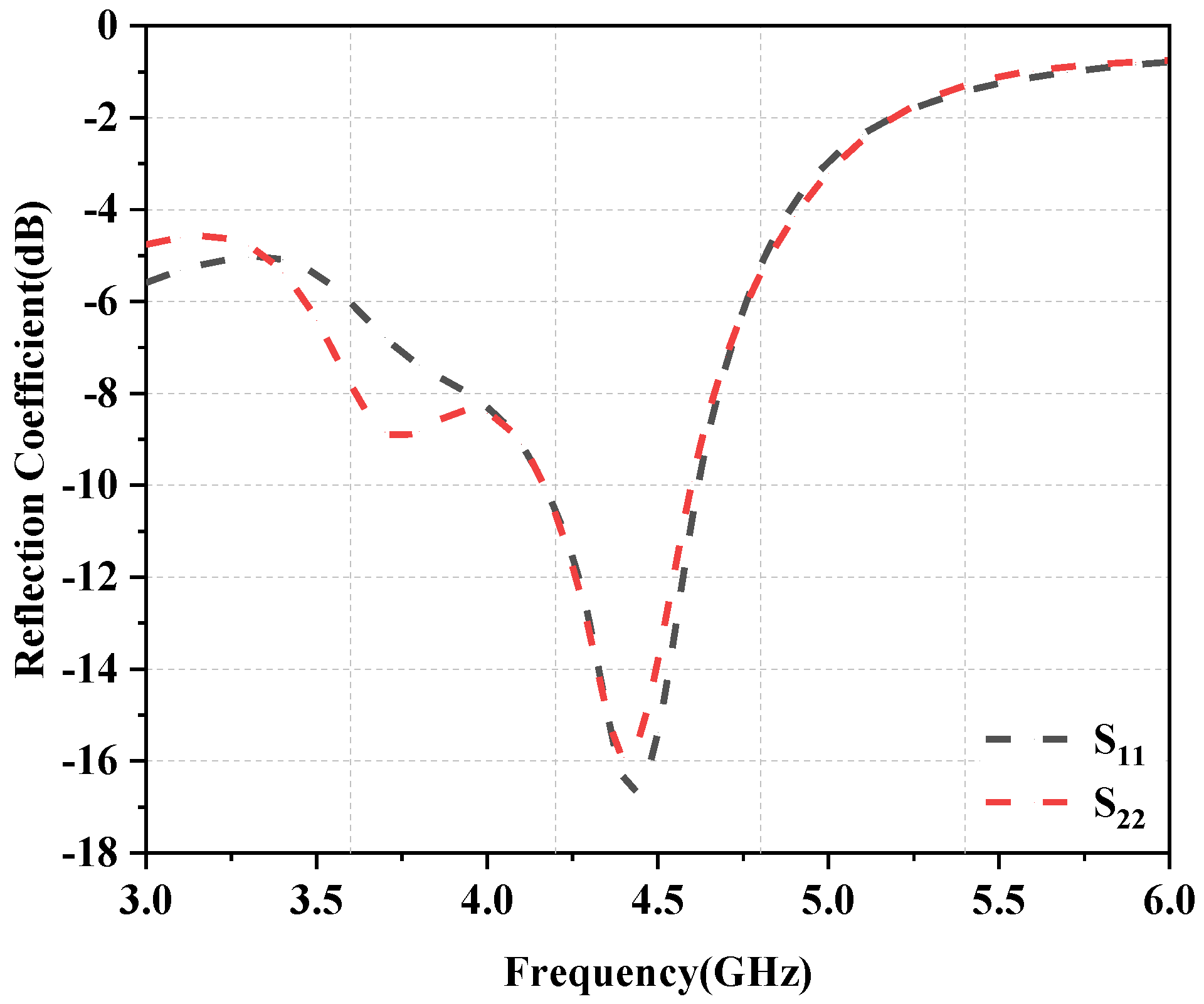
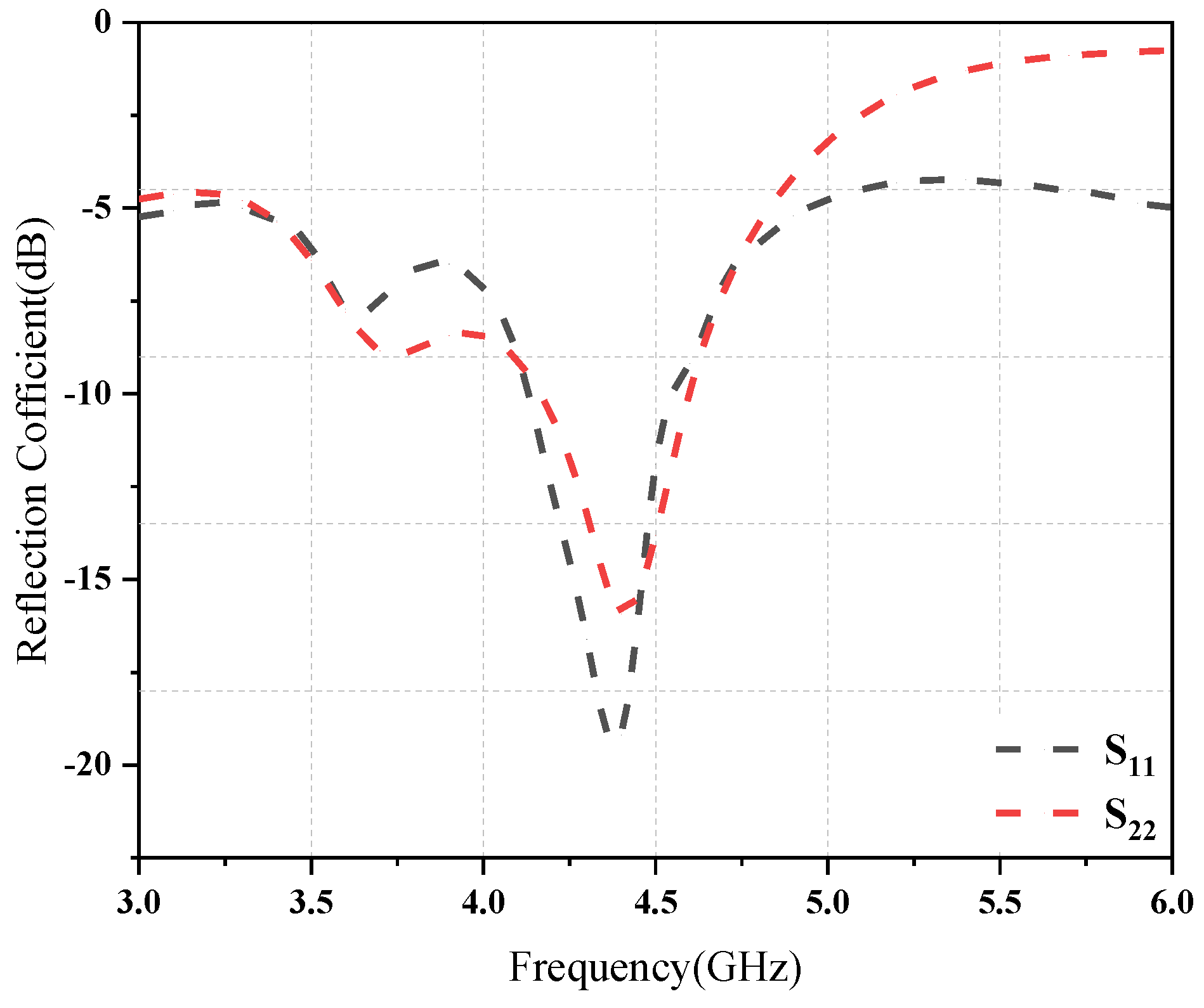
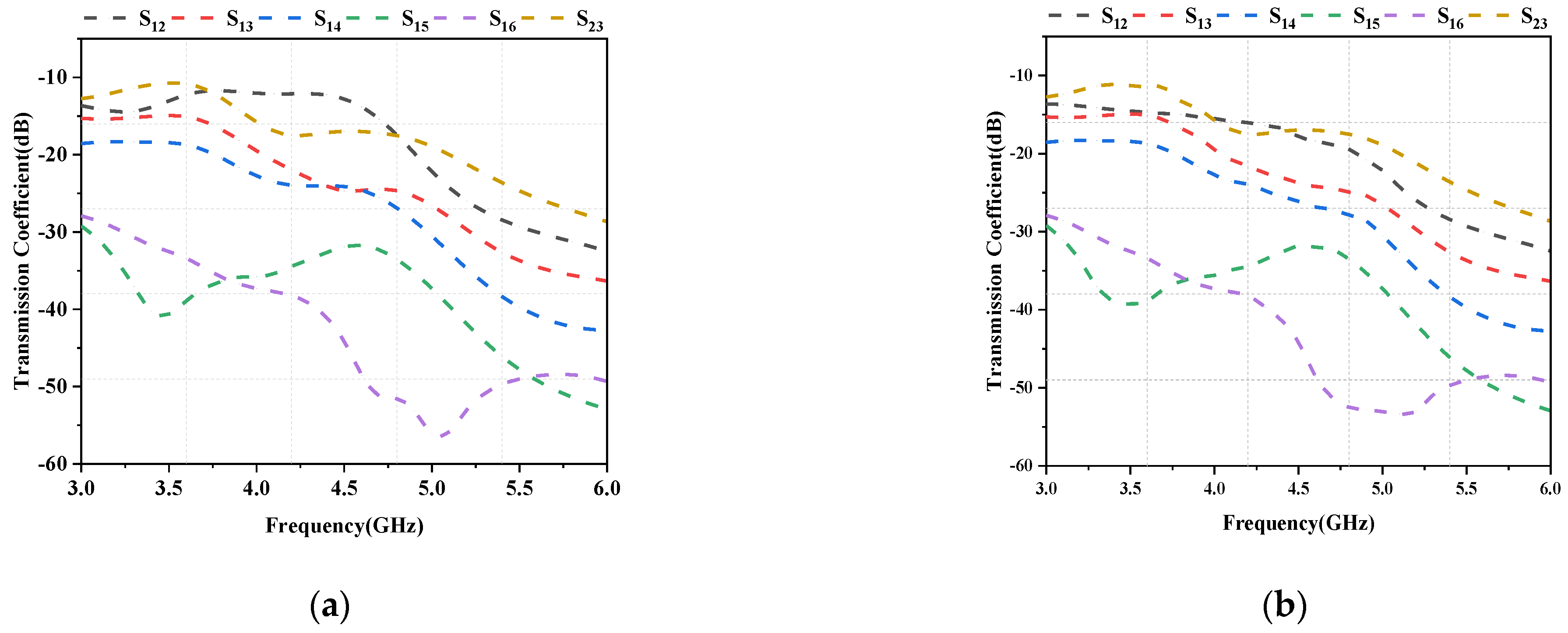
The simulated reflection coefficients for Ant1 and Ant2 are plotted as a function of frequency in Figure 5, and the reflection coefficients are greater than −6 dB in all operating frequency bands. Next, Figure 6 shows the measured reflection coefficient values for Ant1 and Ant2. As is evident from the figures, the simulation findings are quite similar to the test results. The proposed antenna exhibits near-ideal measured 6 dB impedance bandwidths (3:1 VSWR) of 5.71% (at 3400–3600 MHz), 5.40% (at 3600–3800 MHz), and 6.59% (at 4400–4700 MHz). Figure 7a shows the simulated coupling values for various antenna element combinations, while Figure 7b shows the corresponding measured values. The isolation amplitude is greater than 11 dB in the covered 5G NR band (N77/N78/N79).
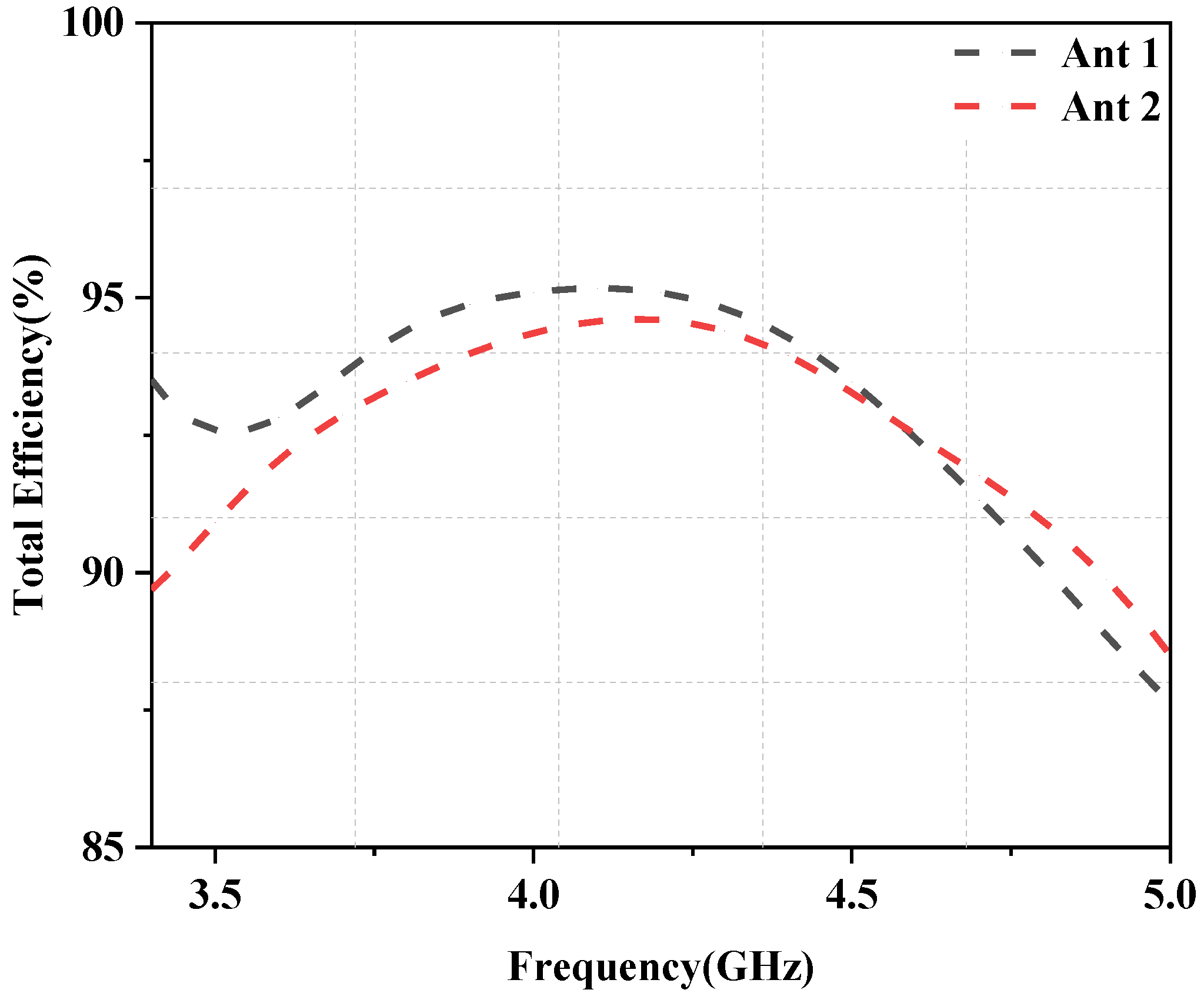
Figure 8 shows the planned antenna measurement setup in a microwave-protected far-field anechoic chamber. Meanwhile, the simulated radiation efficiency values for Ant1 and Ant2, which were found to be greater than 87%, are shown in Figure 9.

3.2. Radiation Patterns and Antenna Peak Gain

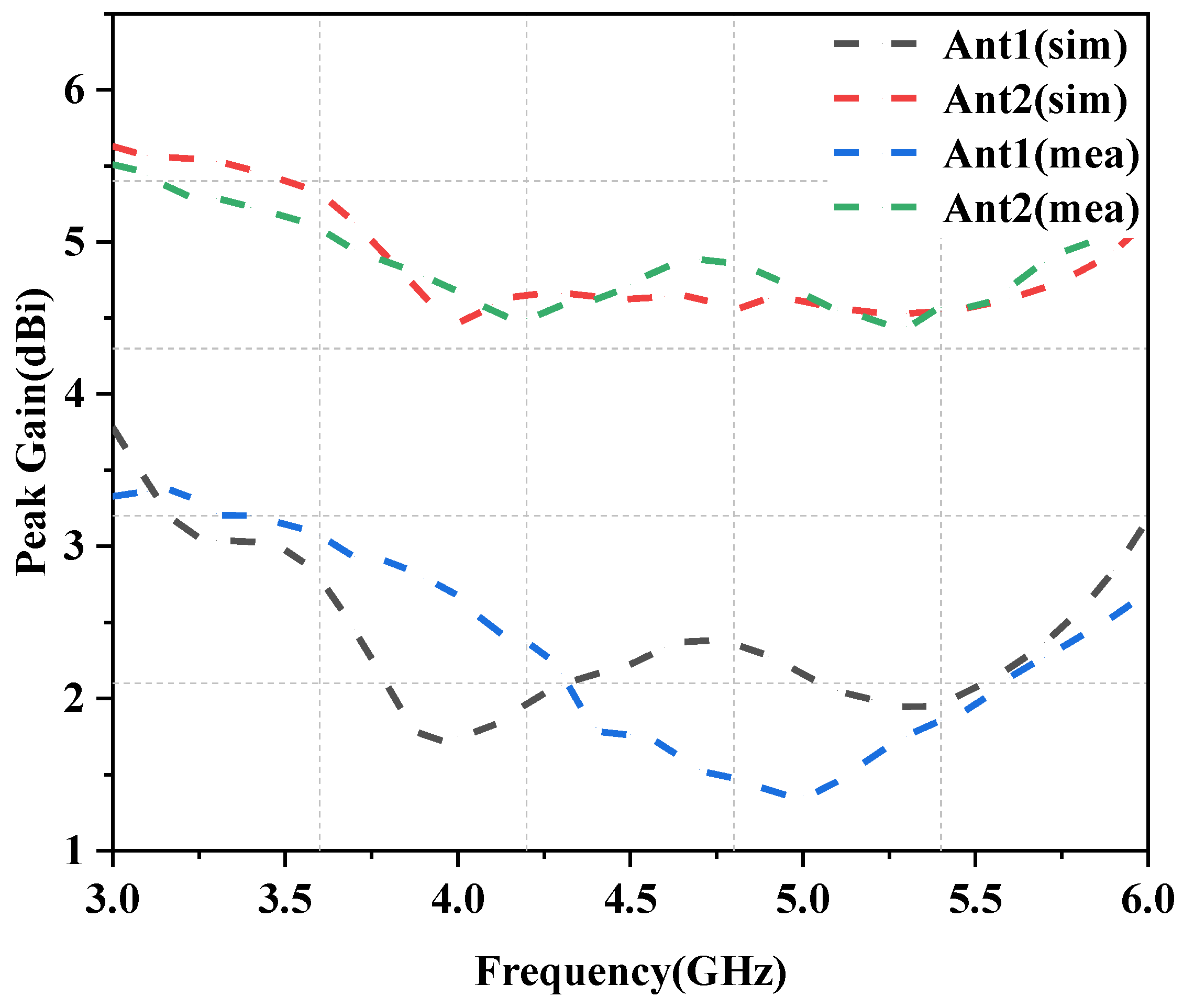
The computed gain of single antenna element is larger than 1.9 dBi in Figure 10, whereas the observed gain is greater than 1.5 dBi over the whole frequency range. In addition, the simulated and measured radiated efficiency of antennas 1 and 2 in the XOZ and YOZ planes are shown in Figure 11. It can be seen that for the XOZ radiation plane, the higher radiation gain directions of Ant1 and Ant2 are close to 90° and 270°, respectively. On the other hand, Ant1 and Ant2 can both efficiently generate an omnidirectional radiation pattern in the YOZ plane. However, due to the influence of the test environment, there are inevitably some errors between the simulation and actual measurement of the two-dimensional radiation pattern of the antenna.

3.3. Diversity and Multiplexing Performance

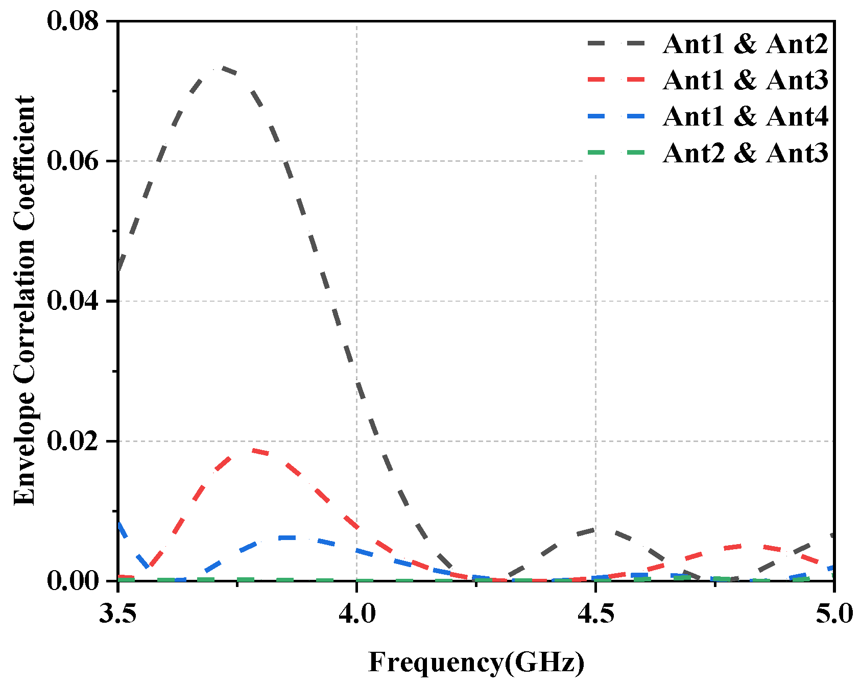
In general, the performance of MIMO antennas is primarily determined by the antenna elements’ diversity and multiplexing capabilities. As a result, it is critical to examine the multiplexing and diversity performance of MIMO antenna arrays in addition to the S-parameters and radiation characteristics. In this regard, the Envelope Correlation Coefficient (ECC) is the most important metric for estimating and validating antenna diversity characteristics, which can be calculated using Equation (1) [27]. It can be seen from Figure 12 that the calculated ECC value is less than 0.08 in the entire operating frequency range for the proposed design, thereby indicating a good diversity performance.
E C C = S 12 * S 12 + S 21 * S 22 2 1 S 11 2 S 21 2 1 S 22 2 S 12 2

3.4. Comparison with Existing 5G Smartphone Antennas

To verify the superiority of the proposed antenna array, we compared the proposed design with the several previously reported designs, as shown in Table 1. It can be concluded that the eight-element antenna proposed in this paper provides a wider bandwidth compared to the existing designs. Furthermore, the design presented in this article provides better isolation, ECC, and overall efficiency values, thus overcoming the bandwidth limitations at a lower cost. That is to say, the proposed design can not only be used for multi-band applications of 5G smartphones, but also adapt to the development of future 6G mobile communications.

4. Effect of User’s Hand

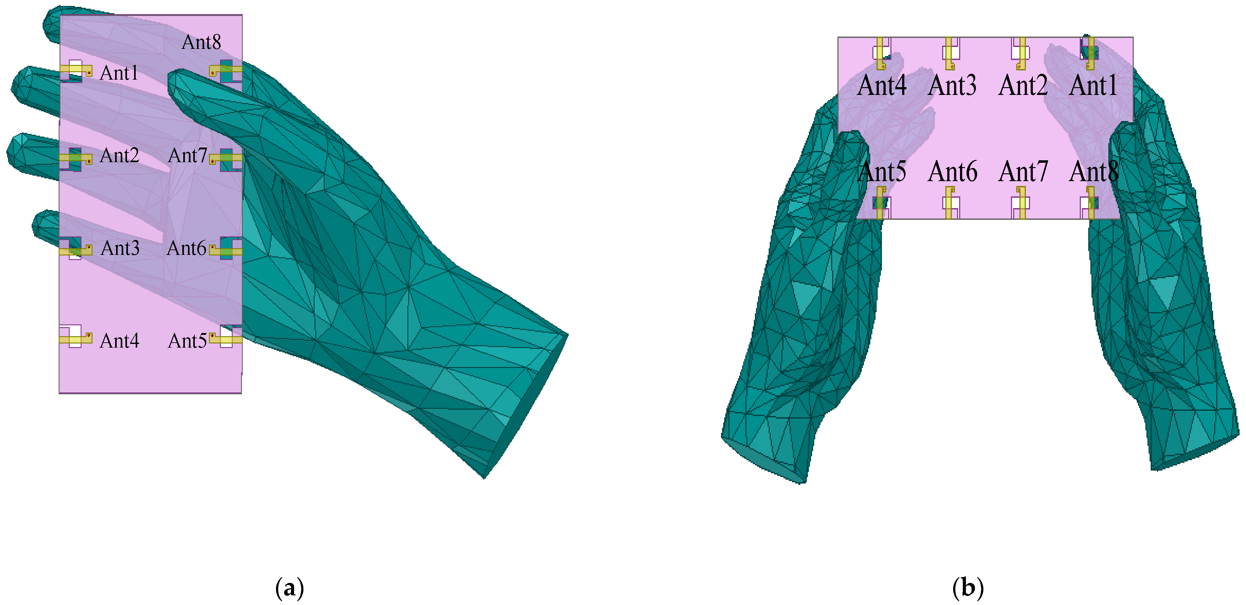
The practical antenna performance is discussed in this section. As depicted in Figure 13, the most commonly used operation modes of the antenna embedded in a smartphone are single-handset mode (SHM) and double-handset mode (DHM). The effect on the user’s head will not be discussed here because the operation is only for data transmission and not for call mode.
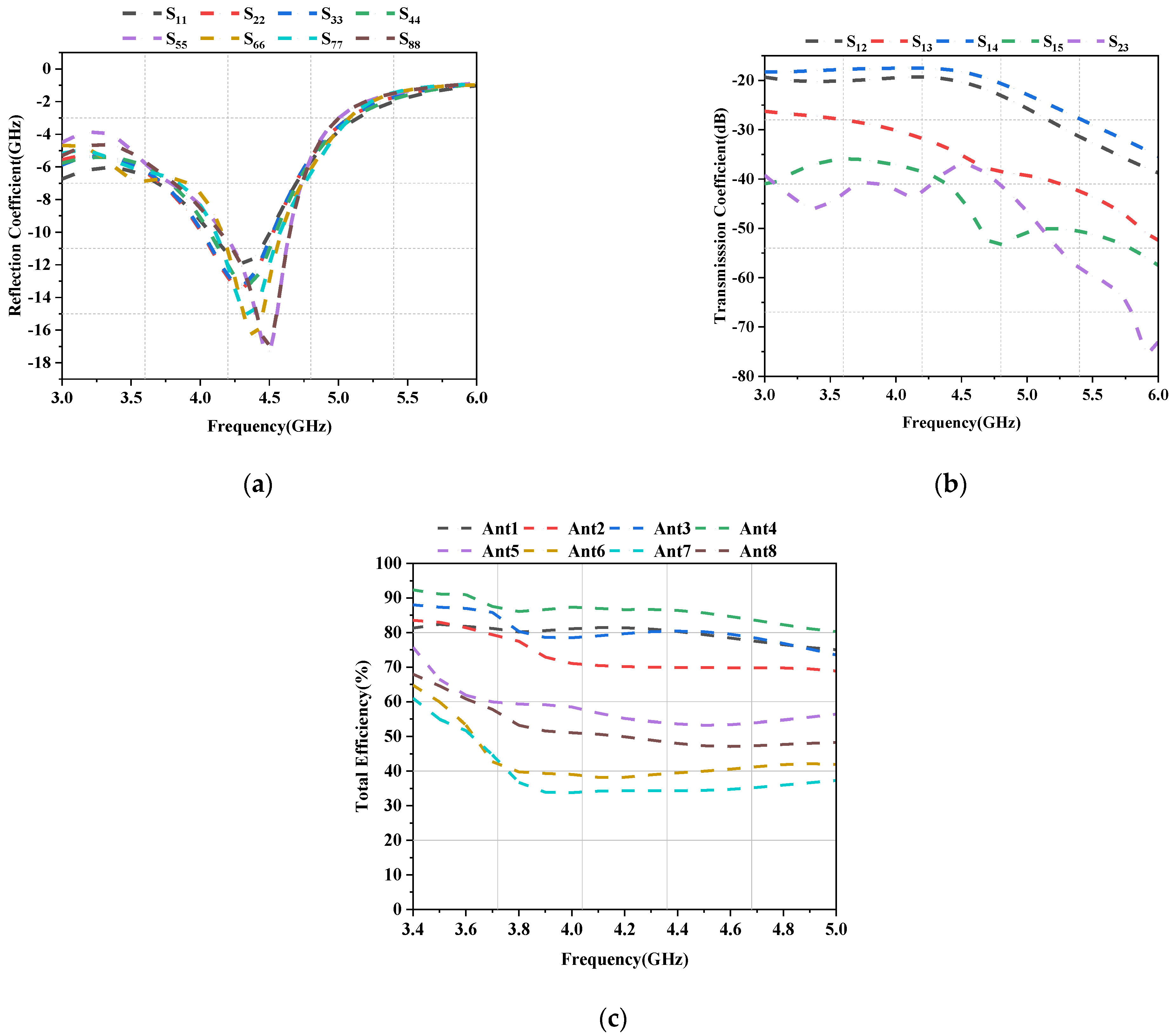
Figure 13a shows the hand configuration with the proposed antenna design in one-handed mode (SHM). Similarly, Figure 13b shows the proposed antenna design in two-handed mode (DHM). Because of their direct contact with the finger, Ant5, Ant6, Ant7, Ant8, and Ant2 exhibit high reflection coefficients under SHM, as shown in Figure 14a. In contrast, because they are farther away from the fingers and still operate in the 3.4–4.7 GHz band, Ant1, Ant3, and Ant4’s reflection coefficients are less affected. Ant1, Ant3, and Ant4’s reflection coefficients, on the other hand, are less affected because they are farther away from the fingers and still cover the 3.4–4.7 GHz band. Their reflection coefficient, however, is slightly higher than in the situation with no hand interference. Nonetheless, the isolation over the entire/desired operating band is greater than 10 dB for all antennas. Besides, as shown in Figure 14c, the radiation efficiency of Ant6 and Ant7 reduces to less than 65%, since the hand tissue can absorb electromagnetic waves. Similarly, Ant2 and Ant8 are also less efficient owing to their proximity to the palm. On the contrary, Ant1 and Ant4 are located far from the hand and hence show efficiency greater than 80%.
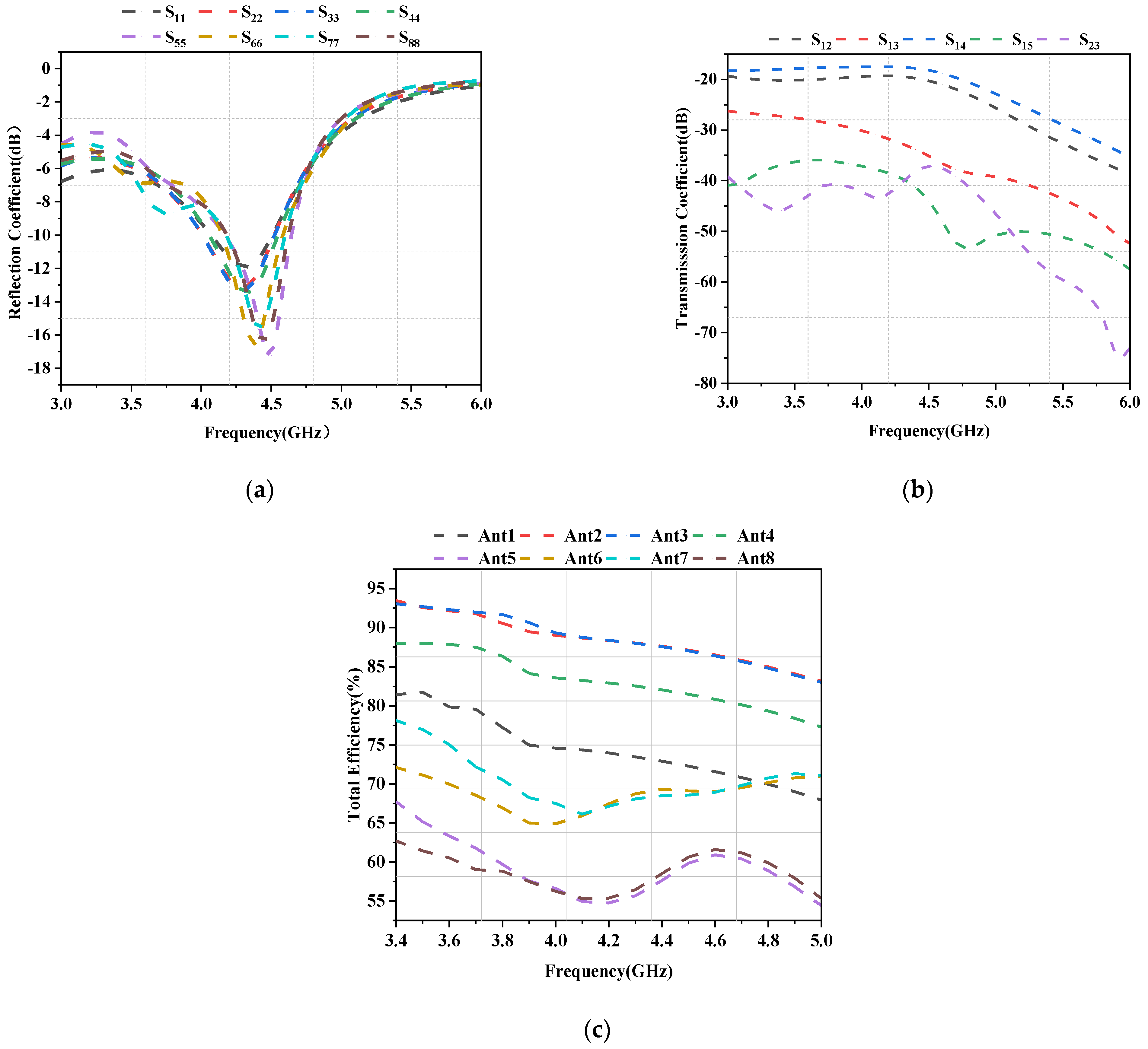
As shown in Figure 15a, only Ant5 and Ant8 are in direct contact with the fingers for DHM, while all other antenna elements are not. Ant5 and Ant8 have significantly higher reflection coefficients because they are covered by the thumb. The radiation efficiency of the antenna elements that are not in contact with the fingers or palm remains greater than 85% over the entire operating band, as shown in Figure 15b. However, for Ant5 and Ant8 that were in contact with the finger, the efficiency was significantly reduced, with a maximum efficiency of only around 60%.

5. Conclusions

This paper proposes an eight-port broadband antenna array with high isolation for mobile terminals operating in the 5G NR frequency band. The broadband characteristics of the antenna are achieved by forming an L-shaped open slot by adding an I-shaped open branch on one side of the metal plate’s rectangular slot. The proposed antenna array effectively covers the required frequency band (3.4–4.7 GHz), which corresponds to the N77/N78/N79 bands of 5G communication. The proposed antenna system offers suppressed mutual coupling (<−10 dB), high overall antenna efficiency (87%–96%), and an excellent envelope correlation coefficient (<0.08). This work also simulates the practical application scenarios of the proposed antenna array in the data transmission mode, revealing that the proposed design performs well in such scenarios. In addition, because the antenna has the characteristics of high frequency bandwidth efficiency, it can be used for 6G mobile communication and can better adapt to future communication development.

Author Contributions

Conceptualization, W.Y.; methodology, M.Y. and Z.W.; software, W.Y. and W.N.; validation, W.Y. and M.Y.; investigation, W.M.; writing—original draft preparation, W.Y.; writing—review and editing, W.Y. and W.M.; supervision, Z.W. All authors have read and agreed to the published version of the manuscript.

Funding

This work was supported in part by the Anhui Provincial Natural Science Foundation of China under Grant no. 2108085MF200, in part by the Natural Science Foundation of Anhui Provincial Education Department under Grant no. KJ2020A0307 and no. 2022AH051583, in part by the High-level Talents Research Funding Project of West Anhui University under Grant no. WGKQ2022009, in part by the Academic Funding Project for Distinguished Top Talents of Colleges and Universities in Anhui Province under Grant no. gxbjZD2021088, and in part by Graduate Innovation Fund of Anhui University of Science and Technology under Grant no. 2021CX2070.

Institutional Review Board Statement

Not applicable.

Informed Consent Statement

Not applicable.

Data Availability Statement

Not applicable.

Conflicts of Interest

The authors declare no conflict of interest.

References

  1. Agiwal, M.; Roy, A.; Saxena, N. Next Generation 5G Wireless Networks: A Comprehensive Survey. IEEE Commun. Surv. Tutor. 2016, 18, 1617–1655. [Google Scholar] [CrossRef]
  2. Chen, H.D.; Tsai, Y.C.; Sim, C.Y.D.; Kuo, C. Broadband eight-antenna array design for sub-6 GHz 5G NR bands metal-frame smartphone applications. IEEE Antennas Wirel. Propag. Lett. 2020, 19, 1078–1082. [Google Scholar] [CrossRef]
  3. Ren, A.D.; Liu, Y.; Yu, H.W.; Jia, Y.; Sim, C.Y.D.; Xu, A.Y. A High-Isolation Building Block Using Stable Current Nulls for 5G Smartphone Applications. IEEE Access 2021, 7, 170419–170429. [Google Scholar] [CrossRef]
  4. Cheng, B.; Du, Z.W. A Wideband Low-Profile Microstrip MIMO Antenna for 5G Mobile Phones. IEEE Trans. Antennas Propag. 2022, 70, 1476–1481. [Google Scholar] [CrossRef]
  5. Bait-Suwailam, M.M.; Almoneef, T.S.; Saeed, S.M. Wideband MIMO antenna with compact decoupling structure for 5G wireless communication applications. Prog. Electromagn. Res. Lett. 2021, 100, 117–125. [Google Scholar] [CrossRef]
  6. Ban, Y.L.; Li, C.; Sim, C.Y.D.; Wu, G.; Wong, K.L. 4G/5G multiple antennas for future multi-mode smartphone applications. IEEE Access 2016, 4, 2981–2988. [Google Scholar] [CrossRef]
  7. Cai, Q.; Li, Y.; Zhang, X.; Shen, W. Wide band MIMO antenna array covering 3.3–7.1 GHz for 5 G metal-rimmed smartphone applications. IEEE Access 2019, 7, 42070–42084. [Google Scholar] [CrossRef]
  8. Chang, L.; Yu, Y.; Wei, K.; Wang, H. Polarization-orthogonal co-frequency dual antenna pair suitable for 5G MIMO smartphone with metallic bezels. IEEE Trans. Antennas Propag. 2019, 67, 5212–5220. [Google Scholar] [CrossRef]
  9. Hu, W.; Liu, X.; Gao, S.; Wen, L.-H.; Qian, L.; Feng, T.; Xu, R.; Fei, P.; Liu, Y. Dual-band ten-element MIMO array based on dual-mode IFAs for 5G terminal applications. IEEE Access 2019, 7, 178476–178485. [Google Scholar] [CrossRef]
  10. Jaglan, N.; Gupta, S.D.; Kanaujia, B.K.; Sharawi, M.S. 10 element sub-6-GHz multi-band double-T based MIMO antenna system for 5G smartphones. IEEE Access 2021, 9, 118662–118672. [Google Scholar] [CrossRef]
  11. Jain, P.; Thourwa, A.; Sardana, N.; Kumar, S.; Gupta, N.; Singh, A.K. I-shaped metamaterial antenna for X-band applications. Prog. Electromagn. Res. Syrmposium-Spring PIERS 2017, 7, e22800. [Google Scholar]
  12. Jha, P.; Kumar, A.; De, A.; Jain, R.K. Modified CSRR based dual-band four-element MIMO antenna for 5G smartphone communication. Prog. Electromagn. Res. Lett. 2021, 101, 35–42. [Google Scholar] [CrossRef]
  13. Jiang, W.; Liu, B.; Cui, Y.; Hu, W. High-isolation eight-element MIMO array for 5Gsmartphone applications. IEEE Access 2019, 19, 34104–34112. [Google Scholar] [CrossRef]
  14. Liu, D.; Luo, Q.H.J.; Zhang, M.; Wen, H.L.; Wang, B.; Wang, J. An extremely low-profile wideband MIMO antenna for 5G smartphones. IEEE Trans. Antennas Propag. 2019, 67, 5772–5780. [Google Scholar] [CrossRef]
  15. Parchin, N.O.; Basherlou, H.J.; Yasir Al-Yasir, I.A.; Sajedin, M.; Rodriguez, J.; Abd-Alhameed, R.A. Multi-mode smartphone antenna array for 5G massive MIMO applications. In Proceedings of the 14th European Conference on Antennas and Propagation (EuCAP), Copenhagen, Denmark, 15–20 March 2020; pp. 1–4. [Google Scholar]
  16. Piao, H.; Jin, Y.; Qu, L. Isolated ground-radiation antenna with inherent decoupling effect and its applications in 5G MIMO antenna array. IEEE Access 2020, 8, 139892–139902. [Google Scholar] [CrossRef]
  17. Srinivasarao, G. Algorithm approach to multiple input multiple output (MIMO) systems. Int. J. Innov. Res. Comput. Commun. Eng. 2015, 3, 11918–11924. [Google Scholar]
  18. Wong, K.L.; Tsai, C.Y.; Lu, J.Y. Two asymmetrically mirrored gap-coupled loop antennasas a compact building block for eight-antenna MIMO array in the future smartphone. IEEE Trans. Antennas Propag. 2017, 65, 1765–1778. [Google Scholar] [CrossRef]
  19. Yuan, X.T.; Chen, Z.; Gu, T.; Yuan, T. A wideband PIFA-pair-based MIMO antenna for 5G smartphones. IEEE Antennas Wirel. Propag. Lett. 2021, 20, 371–375. [Google Scholar] [CrossRef]
  20. Zhang, X.; Li, Y.; Wang, W.; Shen, W. Ultra-wideband 8-port MIMO antenna array for 5G metal-frame smartphones. IEEE Access 2019, 7, 72273–72282. [Google Scholar] [CrossRef]
  21. Zhao, A.; Ren, Z. Size reduction of self-isolated MIMO antenna system for 5G mobile phone applications. IEEE Antennas Wirel. Propag. Lett. 2019, 18, 152–156. [Google Scholar] [CrossRef]
  22. Zhao, A.; Ren, Z. Wideband MIMO antenna systems based on coupled-loop antenna for 5GN77/N78/N79 applications in mobile terminals. IEEE Access 2019, 7, 93761–93771. [Google Scholar] [CrossRef]
  23. Zhao, X.; Yeo, S.P.; Ong, L.C. Decoupling of inverted-F antennas with high-order modes of ground plane for 5G mobile MIMO platform. IEEE Trans. Antennas Propag. 2018, 66, 4485–4495. [Google Scholar] [CrossRef]
  24. Sun, L.B.; Feng, H.; Li, Y.; Zhang, Z. Compact 5G MIMO mobile phone antennas with tightly arranged orthogonal-mode pairs. IEEE Trans. Antennas Propag. 2018, 66, 6364–6369. [Google Scholar] [CrossRef]
  25. Ramachandran, A.; Pushpakaran, S.V.; Pezholil, M.; Kesavath, V. A Four Port MIMO Antenna using Concentric Square Ring Patches Loaded with CSRR for High Isolation. IEEE Antennas Propag. Lett. 2016, 15, 1196–1199. [Google Scholar] [CrossRef]
  26. Li, Z.; Du, Z.; Takahashi, M.; Saito, K.; Ito, K. Reducing Mutual Coupling of MIMO Antennas With Parasitic Elements for Mobile Terminals. IEEE Trans. Antennas Propag. 2012, 60, 473–481. [Google Scholar] [CrossRef]
  27. Sharawi, M.S. Printed multi-band MIMO antenma systems and their performance metrics [wireless corner]. IEEE Antennas Propag. Mag. 2013, 55, 218–232. [Google Scholar] [CrossRef]
  28. Jaglan, N.; Gupta, S.D.; Sharawi, M.S. 18 Element Massive MIMO/Diversity 5G Smartphones Antenna Design for Sub-6 GHz LTE Bands 42/43 Applications. IEEE Open J. Antennas Propag. 2021, 2, 533–545. [Google Scholar] [CrossRef]
  29. Li, Y.; Sim, C.Y.D.; Luo, Y.; Yang, G. Metal-frame-integratedeight-element multiple-input multiple-output antenna array in the longterm evolution bands 41/42/43 for fifth generation smartphones. Int. J. RF Microw. Comput.-Aided Eng. 2019, 29, e21495. [Google Scholar] [CrossRef] [Green Version]
  30. Barani, I.R.R.; Wong, K.L.; Zhang, Y.X.; Li, W.Y. Low-profile wideband conjoinedopen-slot antennas fed by grounded coplanar waveguides for 4 × 4 5G MIMO operation. IEEE Trans. Antennas Propag. 2020, 68, 2646–2657. [Google Scholar] [CrossRef]
  31. Chen, S.C.; Chou, L.C.; Hsu, C.I.G.; Li, S.M. Compact sub-6-GHz four- element MIMO slot antenna system for 5G tablet devices. IEEE Access 2020, 8, 154652–154662. [Google Scholar] [CrossRef]
  32. Wong, K.L.; Lin, B.W.; Lin, S.E. High-isolation conjoined loop multi-input multi-output antennas for the fifth-generation tablet device. Microw. Opt. Technol. Lett. 2019, 61, 111–119. [Google Scholar] [CrossRef] [Green Version]
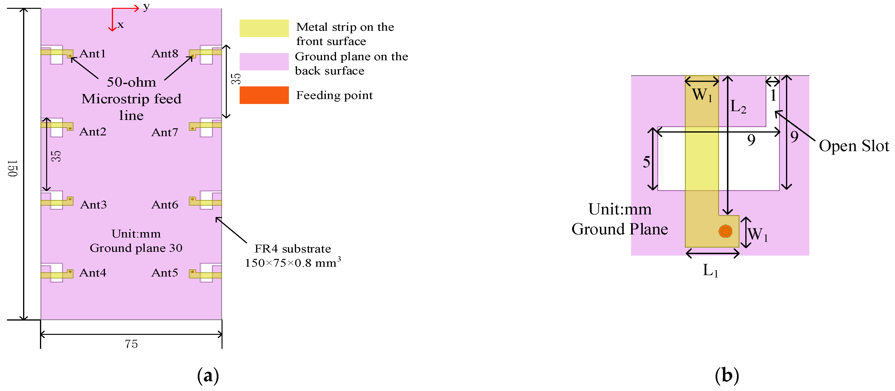
Figure 1. Geometry of the proposed MIMO antenna system. (a) Perspective view. (b) Detailed structure of the slot antenna element (taking Ant1 as an example).
Symmetry 15 00579 g001
Figure 2. Design evolution of the antenna element structure. (a) The structure of the reference and proposed antenna. (b) The comparison of the reflection coefficient between the reference and proposed antenna elements.
Symmetry 15 00579 g002
Figure 3. Surface electric current on the antenna ground plane when Ant1 is excited at 4.4 GHz. (a) Local current distribution. (b) Overall current distribution.
Symmetry 15 00579 g003
Figure 4. Fabricated prototype of the proposed eight-port MIMO antenna system.
Symmetry 15 00579 g004
Figure 5. Simulated reflection coefficient variation with frequency for Ant1 and Ant2.
Symmetry 15 00579 g005
Figure 6. Variation of measured reflection coefficient values with frequency Ant1 and Ant2.
Symmetry 15 00579 g006
Figure 7. Coupling among different antenna pairs. (a) Simulated values of coupling among different antenna pairs. (b) Measured values of coupling among different antenna pairs.
Symmetry 15 00579 g007
Figure 8. Testing environment of the proposed antenna in an anechoic chamber.
Symmetry 15 00579 g008
Figure 9. The total efficiency of Ant1 and Ant2.
Symmetry 15 00579 g009
Figure 10. Simulated (Sim) and Measured (Mea) peak gain values of Ant1 and Ant2.
Symmetry 15 00579 g010
Figure 11. Simulated and measured radiation characteristics at 4.4 GHz. (a) Ant1. (b) Ant2.
Symmetry 15 00579 g011
Figure 12. The calculated Envelope Correlation Coefficient of the proposed MIMO antenna system.
Symmetry 15 00579 g012
Figure 13. Two application scenarios for a hand-held smartphone. (a) SHM. (b) DHM. The practical antenna performance is discussed.
Symmetry 15 00579 g013
Figure 14. Simulated parameters under SHM. (a) Reflection coefficient. (b) Transmission coefficient. (c) Total efficiency.
Symmetry 15 00579 g014
Figure 15. Simulated parameters under DHM. (a) Reflection coefficient. (b) Transmission coefficient. (c) Total efficiency.
Symmetry 15 00579 g015
Table 1. Performance comparison of various state of the art 5G antennas.
ReferencesBandwidth (GHz)Isolation (dB)ECCTotal Efficiency (%)
[6]3.4–3.6(−10 dB)>10<0.262–78
[17]3.4–3.6(−6 dB)>10<0.1540–52
[28]3.3–3.8(−10 dB)>18<0.0187–93
[29]2.496–2.69, 3.4–3.8(−6 dB)>10.5<0.244–46
[30]3.3–4.2(−6 dB)>9.5<0.0640–58
[31]3.4–3.6(−6 dB)>11<0.2340–53
[32]3.3–4.2(−6 dB)>12<0.150–77
[8]3.4–3.6(−6 dB)>12.7<0.1329.2–54
Proposed3.4–4.7(−6 dB)>11<0.0887–96
Disclaimer/Publisher’s Note: The statements, opinions and data contained in all publications are solely those of the individual author(s) and contributor(s) and not of MDPI and/or the editor(s). MDPI and/or the editor(s) disclaim responsibility for any injury to people or property resulting from any ideas, methods, instructions or products referred to in the content.