

Modern Active Voltage Control in Distribution Networks, including Distributed Generation, Using the Hardware-in-the-Loop Technique

 ,
, 
Abstract
:1. Introduction
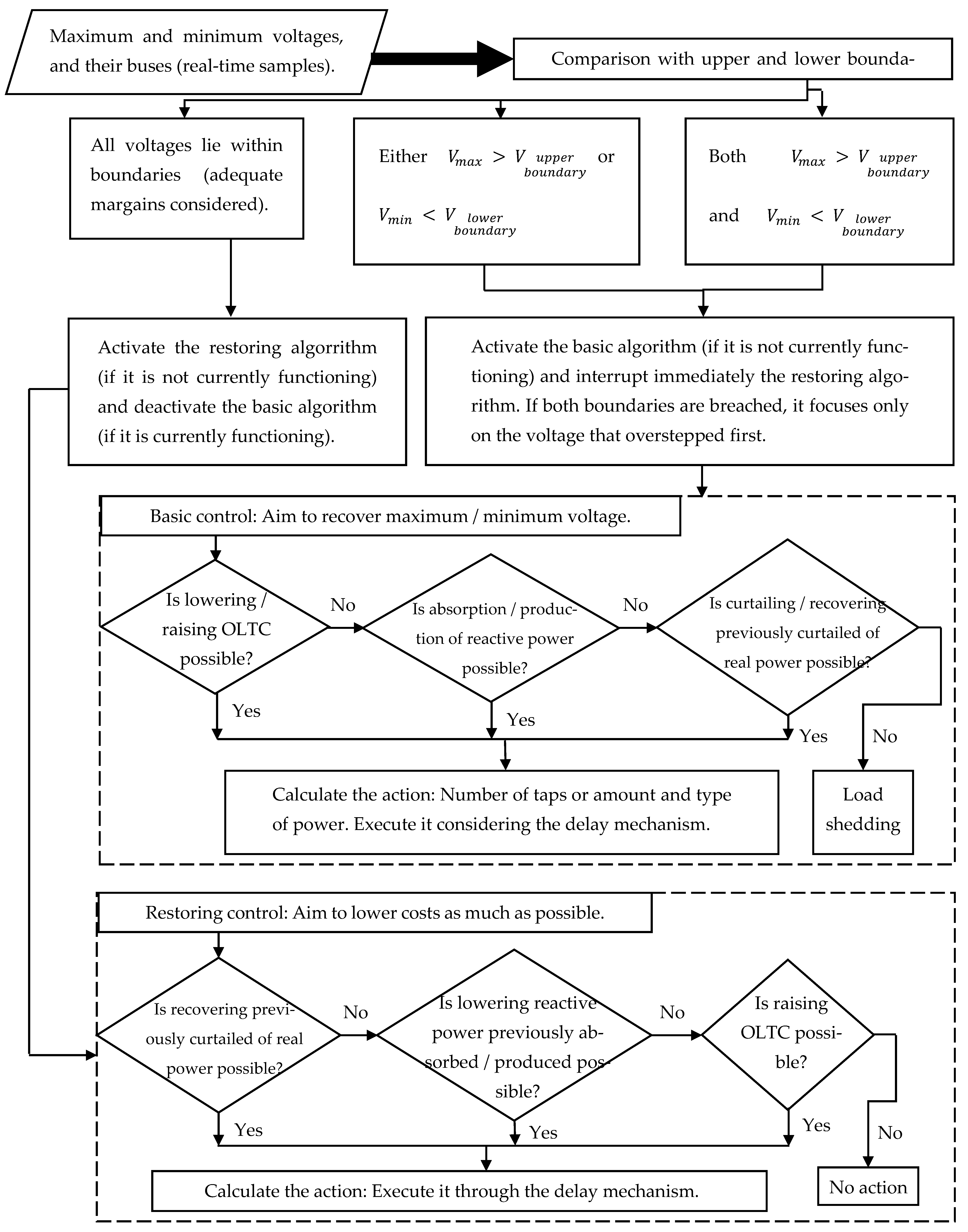
2. Coordinated Control Algorithm
- On-load Tap Changer (OLTC): Utilizing the OLTC of the primary transformer is the simplest and cheapest way to regulate the network voltages, with no cost of high infrastructure for communication links or huge power losses through the network. However, it is inefficient in some cases, where the difference between the extreme (maximum and minimum) voltage of the network is close to the difference between the predefined limits. In these cases, when the maximum voltage exceeds the upper limit of the network and the OLTC decreases the whole network voltage, the minimum voltage of the network will decrease below the network’s lower limit, causing the OLTC to be in a state of successive ups and downs. This problem is solved by deactivating the OLTC in case the other extreme voltage is too close to its limit [34]. Another adaptive OLTC voltage control focused only on the correction of the false image of the network load that has not taken the influence of DG into consideration [35]. In some networks, DNOs prefer to utilize other control tools before the OLTC for mechanical purposes [36].
- Reactive Power Control Using DGs: DG units receive orders from the coordinated control algorithm to absorb or generate some reactive power within their limits. It is more efficient than the OLTC, although it requires a communication network among the DNO and DG units and highly increases network losses. However, it is still cost worthy, considering that normally the cost of losses is much less than the cost of curtailed energy of DGs. Voltage control loss factors were proposed as means of understanding the interactions between reactive power flows, losses, and curtailment [37].
- Curtailing the Real Power of DGs: This tool, like the one before it, depends on a system of communication between DNO and DG units. It is regarded to be the most efficient method for maintaining the network voltages within limits (as proven in [11]). However, since it is the most expensive, it ought to be employed as the last choice after all other alternatives have been exhausted.
- OLTC: the OLTC is regarded as inaccessible for control if the other extreme network voltage is too near to the other boundary by less than a single tap step added to a reasonable margin. Otherwise, the desired number of taps is computed so that the overstepped voltage returns within boundaries. Consequently, it is actuated after a preset delay period of time to skip short voltage variations.
- Absorption or production of reactive powers from DG units: The voltage sensitivities of the buses of extreme voltages with regard to all of the reactive power controllable units are estimated beforehand [39]. The highest sensitivity unit (i.e., lowest reactive power that is needed from it) to the node of the overstepped voltage is picked, provided that this unit has not reached its full capacity of reactive power and will not lead other voltages to cross the other boundary simultaneously. The quantity desired to be absorbed/produced by this unit is estimated, and the requisite quantity is subsequently implemented after a predefined delay period. In case the stated conditions are not fulfilled, then this tool is deemed unavailable for voltage regulation.
- Curtailment of active power produced by DGs: It is similar to the preceding one except that it functions for the real powers of DGs, which only the DNO is capable of lowering. If the network cannot maintain all voltages within boundaries, even if no real power is injected into the network in any way, load shedding is the only alternative left in this situation.
- Both the basic and restoring control parts possess their own time delay. When activating a control part and deactivating the other one, it must wait for a preset time delay for the purpose of bypassing transient and rapid voltage surges.
- The DNO must wait after each decision for its special time delay. It ought to examine its implications in the network before deciding the next action. That time delay is prescribed based on the number of taps, mechanical activation time of the OLTC, time constants of generators, and the quantity of power upgrading.
- If a decision has been proven to be insufficient after its delay time, the system performs the next step immediately and does not apply the time delays of basic and restoring parts. The purpose is to prevent the risk of an extreme voltage violation for an extended period of time. The procedure is repeated until the regulation of all voltages for the basic part, or the optimal situation for restoring the part is achieved.
- In case a voltage boundary breach occurred during the application of a restoring control, the restoring control is immediately stopped, and the basic control restarts functioning.
3. Real-Time Simulations
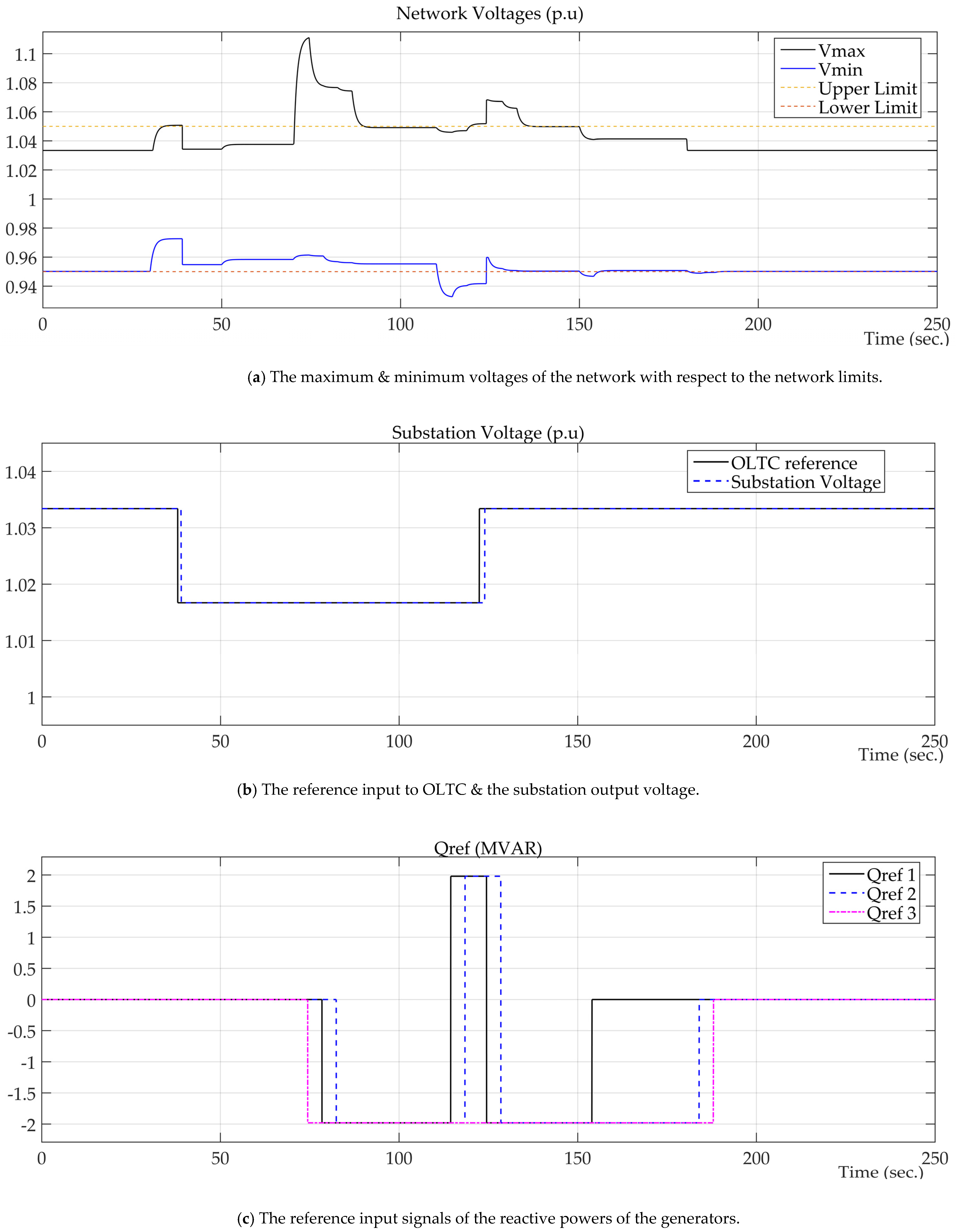
- The control algorithm would not tend to recover the maximum voltage until the minimum voltage is restored within limits first (the first event to occur is handled first.)
- The option of the OLTC is not unavailable anymore, as the maximum voltage has overstepped the upper limit already. When such a scenario occurs (a violation of both limits at the same time), the algorithm obviously cannot regulate both voltages at the same time without causing instability in the system. The voltage control algorithm is set to regulate the voltage violated limits, first neglecting its implications to the other extreme voltage, then regulating the latter voltage afterward.
- Time delays in both the algorithm and the connection of HIL components are apparent. For example, when the maximum voltage of the network exceeded its upper limit at t = 70.34 s., the first control action was taken at t = 74.43 s. after a period of time slightly larger than the 4 s. set for the delay of the basic control algorithm.
- Power losses may be relatively high in some instants. They increased from 186.27 kW in case of no contribution of DG units, to 801.72 kW (a steady state value at t = 89.83 s) in case of the maximum possible contribution of real powers from DG units and their full capacity of reactive power absorption. However, they are negligible compared to the real powers enabled by DG units (16.20 MW), which may be stored in energy storage systems or transported and sold to other MV networks, as the simulations emulate the case of maximum generation/minimum load (the worst case for voltage regulation algorithms).
4. Novelty/Contributions of the Article
- i.
- The basic part of the control algorithm was modified such that if the two extreme voltages of the network violate their limits simultaneously at a certain instant the basic control tends to restore the voltage violating first (regardless of the implications of its actions on the other voltage), and then it tends to restore the other one. That boosted the network’s stability and prevented stalling of the system or even the occurrence of wrong actions that may cause unjustified losses. This is considered a major breakthrough since no publications, as far as the authors know, discussed such severe cases, as they often cause the traditional algorithms to get stuck and lead to instability of the network.
- ii.
- The restoring control is modified to check if it is possible to restore any action performed by the basic control, totally or partially, to lower the running cost (due to a disconnection of a certain source or an increase in network loads). Thus, the proposed algorithm guaranteed that more curtailed active power and absorbed reactive power would be restored.
- iii.
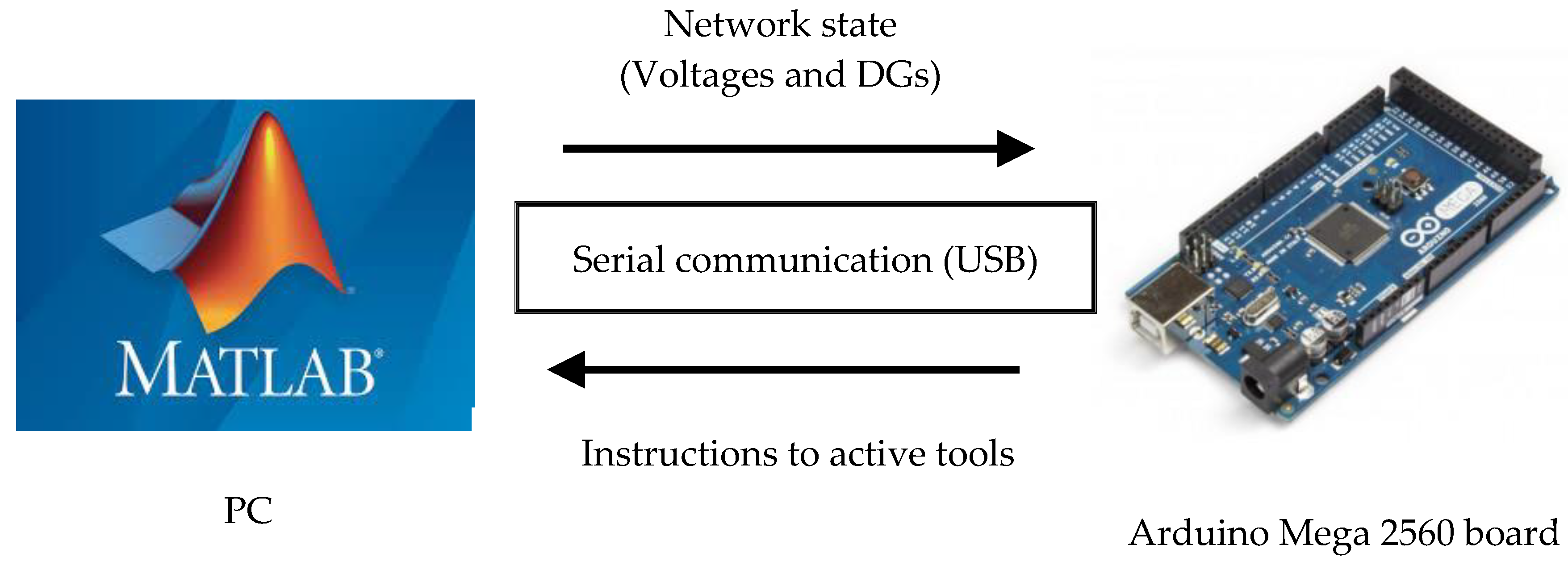
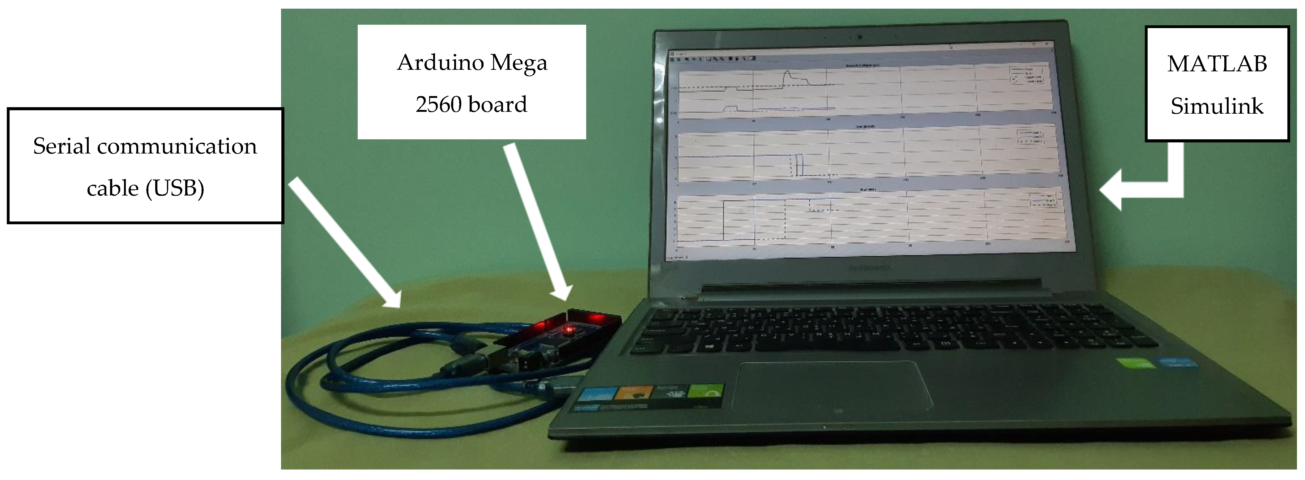
- Implementation of the HIL technique has proven the ability of the system to handle its actions at the right time, demonstrating its reliability and robustness.
5. Conclusions
Author Contributions
Funding
Institutional Review Board Statement
Informed Consent Statement
Data Availability Statement
Conflicts of Interest
Nomenclature
| DG | Distributed Generation |
| DNO | Distribution Network Operator |
| HIL | Hardware-In-the-Loop |
| MATLAB | Matrix Laboratory |
| OLTC | On-load Tap Changer |
Appendix A

| Node | Pload (kW) | Qload (kVAR) |
|---|---|---|
| 1 | 0 | 0 |
| 2 | 100 | 60 |
| 3 | 90 | 40 |
| 4 | 120 | 80 |
| 5 | 60 | 30 |
| 6 | 60 | 20 |
| 7 | 200 | 100 |
| 8 | 200 | 100 |
| 9 | 60 | 20 |
| 10 | 60 | 20 |
| 11 | 45 | 30 |
| 12 | 60 | 35 |
| 13 | 60 | 35 |
| 14 | 120 | 80 |
| 15 | 60 | 10 |
| 16 | 60 | 20 |
| 17 | 60 | 20 |
| 18 | 90 | 40 |
| 19 | 90 | 40 |
| 20 | 90 | 40 |
| 21 | 90 | 40 |
| 22 | 90 | 40 |
| 23 | 90 | 50 |
| 24 | 420 | 200 |
| 25 | 420 | 200 |
| 26 | 60 | 25 |
| 27 | 60 | 25 |
| 28 | 60 | 20 |
| 29 | 120 | 70 |
| 30 | 200 | 600 |
| 31 | 150 | 70 |
| 32 | 210 | 100 |
| 33 | 60 | 40 |
References
- Jenkins, N.; Allan, R.; Crossley, P.; Kirschen, D.; Strbac, G. System studies. In Embedded Generation; The Institution of Electrical Engineers: London, UK, 2000. [Google Scholar]
- Niemczyk, J.; Sus, A.; Borowski, K.; Jasiński, B.; Jasińska, K. The Dominant Motives of Mergers and Acquisitions in the Energy Sector in Western Europe from the Perspective of Green Economy. Energies 2022, 15, 1065–1081. [Google Scholar] [CrossRef]
- Etchebehere, V.S.; Lima, J.W.M. Locational Tariff Structure for Radial Network Fixed Costs in a DER Context. IEEE Access 2022, 10, 597–607. [Google Scholar] [CrossRef]
- Wong, S.; Bhattacharya, K.; Fuller, J.D. Long-Term Effects of Feed-In Tariffs and Carbon Taxes on Distribution Systems. IEEE Trans. Power Syst. 2010, 25, 1241–1253. [Google Scholar] [CrossRef]
- Anzalchi, A.; Sarwat, A. Analysis of Carbon Tax as an Incentive Toward Building Sustainable Grid with Renewable Energy Utilization. In Proceedings of the 2015 Seventh Annual IEEE Green Technologies Conference, New Orleans, LA, USA, 15–17 April 2015. [Google Scholar]
- Marcelo, J.A.; Rupolo, D.; Mantovani, J.R.S. A New Approach to Determine a Distribution Network Usage Fee for Distributed Generators. In Proceedings of the 2021 IEEE PES Innovative Smart Grid Technologies Europe (ISGT Europe), Espoo, Finland, 18–21 October 2021. [Google Scholar]
- Trebolle, D.; Gómez, T. Reliability Options in Distribution Planning Using Distributed Generation. IEEE Lat. Am. Trans. 2010, 8, 557–564. [Google Scholar] [CrossRef]
- Jain, N.; Singh, S.N.; Srivastava, S.C. A Generalized Approach for DG Planning and Viability Analysis Under Market Scenario. IEEE Trans. Ind. Electron. 2013, 60, 5075–5085. [Google Scholar] [CrossRef]
- Santos, L.L.C.; Canha, L.N.; Bernardon, D.P.; Neto, N.K.; Pressi, R.A. Mapping of energetic potential in Southern Brazil to insertion of DG in distribution systems. In Proceedings of the 2015 IEEE PES Innovative Smart Grid Technologies Latin America (ISGT LATAM), Montevideo, Uruguay, 5–7 October 2015. [Google Scholar]
- Kulmala, A.; Repo, S.; Järventausta, P. Coordinated voltage control in distribution networks including several distributed energy resources. IEEE Trans. Smart Grid 2014, 5, 2010–2020. [Google Scholar] [CrossRef]
- Liew, S.N.; Strbac, G. Maximising penetration of wind generation in existing distribution networks. IEE Proc.-Gener. Transm. Distrib. 2002, 149, 256–262. [Google Scholar] [CrossRef]
- Dutta, A.; Ganguly, S.; Kumar, C. Model Predictive Control based Coordinated Voltage Control in Active Distribution Networks utilizing OLTC and DSTATCOM. In Proceedings of the 2020 IEEE International Conference on Power Electronics, Drives and Energy Systems (PEDES), Jaipur, India, 16–19 December 2020. [Google Scholar]
- Sun, X.; Qiu, J.; Yi, Y.; Tao, Y. Cost-Effective Coordinated Voltage Control in Active Distribution Networks With Photovoltaics and Mobile Energy Storage Systems. IEEE Trans. Sustain. Energy 2022, 13, 501–513. [Google Scholar] [CrossRef]
- Chamana, M.; Chowdhury, B.; Jahanbakhsh, F. Distributed Control of Voltage Regulating Devices in the Presence of High PV Penetration to Mitigate Ramp-Rate Issues. IEEE Trans. Smart Grid 2018, 9, 1086–1095. [Google Scholar] [CrossRef]
- Othman, M.M.; Ahmed, M.H.; Salama, M.M.A. A Coordinated Real-Time Voltage Control Approach for Increasing the Penetration of Distributed Generation. IEEE Syst. J. 2020, 14, 699–707. [Google Scholar] [CrossRef]
- Zhang, Y.; Zhang, Q.; Wang, H.; Yu, D. Hierarchical Coordinated Voltage Correction Scheme for Active Distribution Network. In Proceedings of the 2020 IEEE 4th Conference on Energy Internet and Energy System Integration (EI2), Wuhan, China, 30 October–1 November 2020. [Google Scholar]
- Tshivhase, N.; Hasan, A.N.; Shongwe, T. An Average Voltage Approach to Control Energy Storage Device and Tap Changing Transformers under High Distributed Generation. IEEE Access 2021, 9, 108731–108753. [Google Scholar] [CrossRef]
- Jiao, W.; Chen, J.; Wu, Q.; Li, C.; Zhou, B.; Huang, S. Distributed Coordinated Voltage Control for Distribution Networks With DG and OLTC Based on MPC and Gradient Projection. IEEE Trans. Power Syst. 2022, 37, 680–690. [Google Scholar] [CrossRef]
- Mohiuddin, S.M.; Qi, J. Optimal Distributed Control of AC Microgrids With Coordinated Voltage Regulation and Reactive Power Sharing. IEEE Trans. Smart Grid 2022, 13, 1789–1800. [Google Scholar] [CrossRef]
- Nandasiri, N.; Pang, C.; Aravinthan, V. Marginal levelized cost of energy bases optimal operation of distribution system considering photovoltaics. In Proceedings of the 2017 North American Power Symposium (NAPS), Morgantown, WV, USA, 17–19 September 2017. [Google Scholar]
- Shigenobu, R.; Yona, A.; Senjyu, T. Demand response considering participation rate in smart grid: Two level optimal management for DisCo and customers. In Proceedings of the 2017 17th International Conference on Control, Automation and Systems (ICCAS), Jeju, Republic of Korea, 18–21 October 2017. [Google Scholar]
- Stanelytė, D.; Radziukynas, V. Analysis of Voltage and Reactive Power Algorithms in Low Voltage Networks. Energies 2022, 15, 1843–1868. [Google Scholar] [CrossRef]
- Gu, M.; Meegahapola, L.; Wong, K.L. Coordinated Voltage and Frequency Control in Hybrid AC/MT-HVDC Power Grids for Stability Improvement. IEEE Trans. Power Syst. 2021, 36, 635–647. [Google Scholar] [CrossRef]
- Han, H.; Li, Q.; Lv, Z. Multi-level Voltage Interaction Control in Active Distribution Network Based on MPC. In Proceedings of the 2019 Chinese Automation Congress (CAC), Hangzhou, China, 22–24 November 2019. [Google Scholar]
- Guo, Y.; Wu, Q.; Gao, H.; Huang, S.; Zhou, B.; Li, C. Double-Time-Scale Coordinated Voltage Control in Active Distribution Networks Based on MPC. IEEE Trans. Sustain. Energy 2020, 11, 294–303. [Google Scholar] [CrossRef]
- Kou, P.; Liang, D.; Gao, R.; Liu, Y.; Gao, L. Decentralized Model Predictive Control of Hybrid Distribution Transformers for Voltage Regulation in Active Distribution Networks. IEEE Trans. Sustain. Energy 2020, 11, 2189–2200. [Google Scholar] [CrossRef]
- Maharjan, S.; Khambadkone, A.M.; Peng, J.C. Robust Constrained Model Predictive Voltage Control in Active Distribution Networks. IEEE Trans. Sustain. Energy 2021, 12, 400–411. [Google Scholar] [CrossRef]
- Hou, Z.; Liu, Y.; Yan, J.; Liao, Y.; Miao, C.; Zhao, R. Voltage control strategy of AVC system based on Data Mining. In Proceedings of the 2022 14th International Conference on Measuring Technology and Mechatronics Automation (ICMTMA), Changsha, China, 15–16 January 2022. [Google Scholar]
- Ping, B.; Zhang, X.; Song, Q.; Yu, Y.; Wu, N.; Ji, X. Voltage control strategy for integrated medium and low voltage distribution network based on active-reactive power coordination optimization. In Proceedings of the 2020 Chinese Automation Congress (CAC), Shanghai, China, 6–8 November 2020. [Google Scholar]
- Sun, X.; Qiu, J.; Tao, Y.; Ma, Y.; Zhao, J. Coordinated Real-Time Voltage Control in Active Distribution Networks: An Incentive-Based Fairness Approach. IEEE Trans. Smart Grid 2022, 13, 2650–2663. [Google Scholar] [CrossRef]
- Gerdroodbari, Y.Z.; Razzaghi, R.; Shahnia, F. Decentralized Control Strategy to Improve Fairness in Active Power Curtailment of PV Inverters in Low-Voltage Distribution Networks. IEEE Trans. Sustain. Energy 2021, 12, 2282–2292. [Google Scholar] [CrossRef]
- Yu, P.; Wan, C.; Sun, M.; Zhou, Y.; Song, Y. Distributed Voltage Control of Active Distribution Networks With Global Sensitivity. IEEE Trans. Power Syst. 2022, 37, 4214–4228. [Google Scholar] [CrossRef]
- Fahmy, B.N.; Soliman, M.H.; Talaat, H.E.A. Active Voltage Control in Distribution Networks including Distributed Generations using Hardware-in-the-Loop Technique. In Proceedings of the 2019 21st International Middle East Power Systems Conference (MEPCON), Cairo, Egypt, 17–19 December 2019. [Google Scholar]
- Kulmala, A.; Repo, S.; Järventausta, P. Active voltage level management of distribution networks with distributed generation using on load tap changing transformers. In Proceedings of the Power Tech, 2007 IEEE Lausanne, Lausanne, Switzerland, 1–5 July 2007. [Google Scholar]
- Švenda, G.; Simendić, Z. Adaptive on-load tap-changing voltage control for active distribution networks. Electr. Eng. 2022, 104, 1041–1056. [Google Scholar] [CrossRef]
- Giacomuzzi, S.; Langwasser, M.; Carne, G.D.; Buja, G.; Liserre, M. Smart transformer-based medium voltage grid support by means of active power control. CES Trans. Electr. Mach. Syst. 2020, 4, 285–294. [Google Scholar] [CrossRef]
- Deakin, M.; Morstyn, T.; Apostolopoulou, D.; McCulloch, M.D. Voltage control loss factors for quantifying DG reactive power control impacts on losses and curtailment. IET Gener. Transm. Distrib. 2022, 16, 2049–2062. [Google Scholar] [CrossRef]
- Meerimatha, G.; Kesavarao, G.; Sreenivasulu, N. A Novel Distribution System Power Flow Algorithm using Forward Backward Matrix Method. IOSR J. Electr. Electron. Eng. 2015, 10, 46–51. [Google Scholar]
- Conti, S.; Raiti, S.; Vagliasindi, G. Voltage sensitivity analysis in radial MV distribution networks using constant current models. In Proceedings of the 2010 IEEE International Symposium on Industrial Electronics, Bari, Italy, 4–7 July 2010. [Google Scholar]


| Time (s) | Vmax (p.u) | Vmin (p.u) | OLTC Ref. | Vss (p.u) | Pref (MW) | Qref (MW) | Ploss (kW) | ||||
|---|---|---|---|---|---|---|---|---|---|---|---|
| DG1 | DG2 | DG3 | DG1 | DG2 | DG3 | ||||||
| 0.00 | 1.033400 | 0.950164 | 1.0334 | 1.0334 | 0.00 | 0.00 | 0.00 | 0.00 | 0.00 | 0.00 | 186.27 |
| 30.01 | 1.033400 | 0.950398 | 1.0334 | 1.0334 | 6.00 | 0.00 | 0.00 | 0.00 | 0.00 | 0.00 | 184.45 |
| 33.89 | 1.050005 | 0.972217 | 1.0334 | 1.0334 | 6.00 | 0.00 | 0.00 | 0.00 | 0.00 | 0.00 | 217.78 |
| 38.00 | 1.050722 | 0.972651 | 1.0167 | 1.0334 | 6.00 | 0.00 | 0.00 | 0.00 | 0.00 | 0.00 | 222.59 |
| 39.00 | 1.034271 | 0.954817 | 1.0167 | 1.0167 | 6.00 | 0.00 | 0.00 | 0.00 | 0.00 | 0.00 | 230.23 |
| 50.01 | 1.034308 | 0.954855 | 1.0167 | 1.0167 | 6.00 | 6.00 | 0.00 | 0.00 | 0.00 | 0.00 | 230.34 |
| 69.97 | 1.037571 | 0.958392 | 1.0167 | 1.0167 | 6.00 | 6.00 | 0.00 | 0.00 | 0.00 | 0.00 | 292.77 |
| 70.01 | 1.037603 | 0.958428 | 1.0167 | 1.0167 | 6.00 | 6.00 | 6.00 | 0.00 | 0.00 | 0.00 | 293.60 |
| 70.34 | 1.050374 | 0.959376 | 1.0167 | 1.0167 | 6.00 | 6.00 | 6.00 | 0.00 | 0.00 | 0.00 | 363.32 |
| 74.43 | 1.111057 | 0.961428 | 1.0167 | 1.0167 | 6.00 | 6.00 | 6.00 | 0.00 | 0.00 | −1.98 | 857.86 |
| 78.75 | 1.077556 | 0.959709 | 1.0167 | 1.0167 | 6.00 | 6.00 | 6.00 | −1.98 | 0.00 | −1.98 | 976.50 |
| 83.22 | 1.075382 | 0.956471 | 1.0167 | 1.0167 | 6.00 | 6.00 | 6.00 | −1.98 | −1.98 | −1.98 | 1048.58 |
| 87.51 | 1.057947 | 0.955625 | 1.0167 | 1.0167 | 6.00 | 6.00 | 4.20 | −1.98 | −1.98 | −1.98 | 878.75 |
| 89.83 | 1.049988 | 0.955362 | 1.0167 | 1.0167 | 6.00 | 6.00 | 4.20 | −1.98 | −1.98 | −1.98 | 801.72 |
| 110.01 | 1.049076 | 0.955115 | 1.0167 | 1.0167 | 0.00 | 6.00 | 4.20 | −1.98 | −1.98 | −1.98 | 790.69 |
| 110.29 | 1.048322 | 0.949761 | 1.0167 | 1.0167 | 0.00 | 6.00 | 4.20 | −1.98 | −1.98 | −1.98 | 729.14 |
| 114.47 | 1.045909 | 0.932724 | 1.0167 | 1.0167 | 0.00 | 6.00 | 4.20 | 1.98 | −1.98 | −1.98 | 697.21 |
| 118.70 | 1.048015 | 0.940633 | 1.0167 | 1.0167 | 0.00 | 6.00 | 4.20 | 1.98 | 1.98 | −1.98 | 591.13 |
| 119.44 | 1.050030 | 0.941211 | 1.0167 | 1.0167 | 0.00 | 6.00 | 4.20 | 1.98 | 1.98 | −1.98 | 575.12 |
| 123.00 | 1.051768 | 0.941708 | 1.0334 | 1.0167 | 0.00 | 6.00 | 4.20 | 1.98 | 1.98 | −1.98 | 568.03 |
| 124.00 | 1.068187 | 0.959811 | 1.0334 | 1.0334 | 0.00 | 6.00 | 4.20 | 1.98 | 1.98 | −1.98 | 550.40 |
| 124.52 | 1.068173 | 0.959664 | 1.0334 | 1.0334 | 0.00 | 6.00 | 4.20 | −1.98 | 1.98 | −1.98 | 549.99 |
| 128.55 | 1.066865 | 0.952039 | 1.0334 | 1.0334 | 0.00 | 6.00 | 4.20 | −1.98 | −1.98 | −1.98 | 624.49 |
| 132.58 | 1.061454 | 0.950706 | 1.0334 | 1.0334 | 0.00 | 6.00 | 3.36 | −1.98 | −1.98 | −1.98 | 667.21 |
| 136.44 | 1.049993 | 0.950303 | 1.0334 | 1.0334 | 0.00 | 6.00 | 3.36 | −1.98 | −1.98 | −1.98 | 581.01 |
| 150.01 | 1.049718 | 0.950261 | 1.0334 | 1.0334 | 0.00 | 0.00 | 3.36 | −1.98 | −1.98 | −1.98 | 578.51 |
| 150.11 | 1.048874 | 0.949928 | 1.0334 | 1.0334 | 0.00 | 0.00 | 3.36 | −1.98 | −1.98 | −1.98 | 567.26 |
| 154.13 | 1.040971 | 0.947281 | 1.0334 | 1.0334 | 0.00 | 0.00 | 3.36 | 0.00 | −1.98 | −1.98 | 495.19 |
| 155.68 | 1.041271 | 0.950035 | 1.0334 | 1.0334 | 0.00 | 0.00 | 3.36 | 0.00 | −1.98 | −1.98 | 444.10 |
| 180.01 | 1.040835 | 0.950745 | 1.0334 | 1.0334 | 0.00 | 0.00 | 0.00 | 0.00 | −1.98 | −1.98 | 431.49 |
| 180.58 | 1.033400 | 0.949966 | 1.0334 | 1.0334 | 0.00 | 0.00 | 0.00 | 0.00 | −1.98 | −1.98 | 329.88 |
| 184.60 | 1.033400 | 0.949168 | 1.0334 | 1.0334 | 0.00 | 0.00 | 0.00 | 0.00 | 0.00 | −1.98 | 282.40 |
| 188.62 | 1.033400 | 0.949810 | 1.0334 | 1.0334 | 0.00 | 0.00 | 0.00 | 0.00 | 0.00 | 0.00 | 213.11 |
| 189.43 | 1.033400 | 0.950011 | 1.0334 | 1.0334 | 0.00 | 0.00 | 0.00 | 0.00 | 0.00 | 0.00 | 193.08 |
| 194.73 | 1.033400 | 0.950164 | 1.0334 | 1.0334 | 0.00 | 0.00 | 0.00 | 0.00 | 0.00 | 0.00 | 186.29 |
| 250.00 | 1.033400 | 0.950164 | 1.0334 | 1.0334 | 0.00 | 0.00 | 0.00 | 0.00 | 0.00 | 0.00 | 186.27 |
Disclaimer/Publisher’s Note: The statements, opinions and data contained in all publications are solely those of the individual author(s) and contributor(s) and not of MDPI and/or the editor(s). MDPI and/or the editor(s) disclaim responsibility for any injury to people or property resulting from any ideas, methods, instructions or products referred to in the content. |
© 2022 by the authors. Licensee MDPI, Basel, Switzerland. This article is an open access article distributed under the terms and conditions of the Creative Commons Attribution (CC BY) license (https://creativecommons.org/licenses/by/4.0/).
Share and Cite
Fanos, B.N.F.; Soliman, M.H.; Talaat, H.E.A.; Attia, M.A. Modern Active Voltage Control in Distribution Networks, including Distributed Generation, Using the Hardware-in-the-Loop Technique. Symmetry 2023, 15, 90. https://doi.org/10.3390/sym15010090
Fanos BNF, Soliman MH, Talaat HEA, Attia MA. Modern Active Voltage Control in Distribution Networks, including Distributed Generation, Using the Hardware-in-the-Loop Technique. Symmetry. 2023; 15(1):90. https://doi.org/10.3390/sym15010090
Chicago/Turabian StyleFanos, Beshoy Nabil Fahmy, Mohammad H. Soliman, Hossam E. A. Talaat, and Mahmoud A. Attia. 2023. "Modern Active Voltage Control in Distribution Networks, including Distributed Generation, Using the Hardware-in-the-Loop Technique" Symmetry 15, no. 1: 90. https://doi.org/10.3390/sym15010090
APA StyleFanos, B. N. F., Soliman, M. H., Talaat, H. E. A., & Attia, M. A. (2023). Modern Active Voltage Control in Distribution Networks, including Distributed Generation, Using the Hardware-in-the-Loop Technique. Symmetry, 15(1), 90. https://doi.org/10.3390/sym15010090