Abstract
Power electronics-based converters have been widely used in several applications, specifically electric propulsion systems. Ongoing advancements in converters have led to high-gain Quadratic Boost Converters (QBC) which control Permanent Magnet Synchronous Motor (PMSM) drive. In this work, a novel scheme is employed, particularly a three-phase inverter between QBC and PMSM operated by a dual-mode controller strategy. Precisely, the novelty of this work is to use the quadratic boost converter to control the PMSM drive by applying different control strategies. This work also demonstrates the simulation of two different current control strategies applied to a Semi-Converter (SC) fed QBC based on PMSM-based EV. It also presents the strategy, inquiry, and model of SC-based QBC three-phase inverter (TPI) fed PMSM with symmetrical operated PI (Proportional Integral), FOPID (Fractional Order Proportional Integral Derivative), and PR (Proportional Resonant) controllers. The simulated results offer a significant improvement in PMSM parameters compared with the PI-PI framework, notably voltage, speed, and torque against source disturbances. Further, the PR-PR control approach provides better time-domain parameters than the PI-PI control strategy (including the least rise time (Tr) of 1.15 s, peak time (Tp) of 2.38 s, settling time (Ts) of 4.12 s, and steady-state error (Ess) of 4.89 s). Furthermore, the experimental module is designed to test the effectiveness of the proposed control strategies and was found to be more advantageous in dual mode symmetric PR-PR controlled SC-based QBC-TPI fed PMSM.
1. Introduction
1.1. Background
Owing to the incessant growth of populations and industries, the consumption proportion of power upsurges speedily every year which upsets the environmental features [1,2,3]. Precisely, fossil fuel-based power production raises greenhouse gas releases that disturb climatic circumstances owing to pollution elements [4,5,6]. Among the releases, carbon dioxide (CO2) is a noteworthy contaminant that causes severe variations in the earth’s atmosphere comportment [5,6,7]. Also, the consequence of pollution on earth and the fast usage of fossil oils deliver a sturdy impulse for the development and progression of electric vehicles (EVs). The expansions in hybrid electric vehicles (HEV) provide the best quick fix near the strictness of the problem on earth. HEVs not only decrease the release of pollution but also decrease fuel costs for customers with their enhanced driving choice and dynamic features sustaining ecological regulations. Power electronics-based converting techniques have been widely used in numerous applications. For instance, renewable power generation schemes, sources likely fuel cells and solar arrays, and other sources (notably battery banks) typically have stumpy-output-voltage scales regarding the nominal necessities of grid-tied inverters [8].
Hypothetically, the conventional boost converter (CBC) has an immeasurable voltage gain by snowballing the duty sequence of the main switch; consequently, it is a significant applicant for step-up junctures. Nevertheless, the voltage tension of the main switch matches the output voltage, which shows a high voltage grade switch with which an augmented price and great on-resistance are mandatory. Furthermore, when an exceedingly high duty cycle is employed, the efficacy and gain of CBC will decline radically owing to the equivalent series resistance of the inductor and reverse recovery concern of the output diode. Taking the above motives into account, the application of CBC is imperfect for those not requiring a high voltage adaptation ratio [9]. In novel switching, table [10] is implemented to achieve a reduced torque ripple. It will give satisfactory performance and reduces acoustic noise and mechanical vibrations [11,12]. Recently, a Matrix Converter fed DTC (MC-DTC) has become used in many industrial applications because of its inherent features, such as maintaining the power factor nearer to the unity and providing flexible, simultaneous control of the torque and flux [13]. To attain a high-voltage gain with an appropriate duty cycle, numerous voltage lift methods, containing switch-capacitor and switch-inductor assemblies, have been examined [14,15,16,17].
1.2. Literature Review
Considering all the needs for advanced power conversion techniques, a robust literature review is carried out using several articles from leading publishers such as IEEE, IET, Elsevier, Springer, MDPI, etc. Some of the notable reports are illustrated in Table 1.
Table 1.
Literature review relating to the converting techniques.
Based on the literature report, it is inferred that there are several converting techniques available for effective power conversion using several control strategies. Also, to the best of the author’s knowledge, none of the researchers applied SC-QBC-TPI fed PMSM drives for dual mode PI, FOPID, and PR controllers, particularly dynamic responses. Therefore, this work investigates the control strategies that can be effectively adapted for power conversion in electric power trains with a better dynamic response.
1.3. Objectives and Contributions
The objectives of this work focus on the integrated control strategy technique for a power converter which has a single-line objective to enhance the dynamic responses of the QBC-TPI fed PMSM drive using the PR controller. Based on this objective, the contributions of this work are listed as follows:
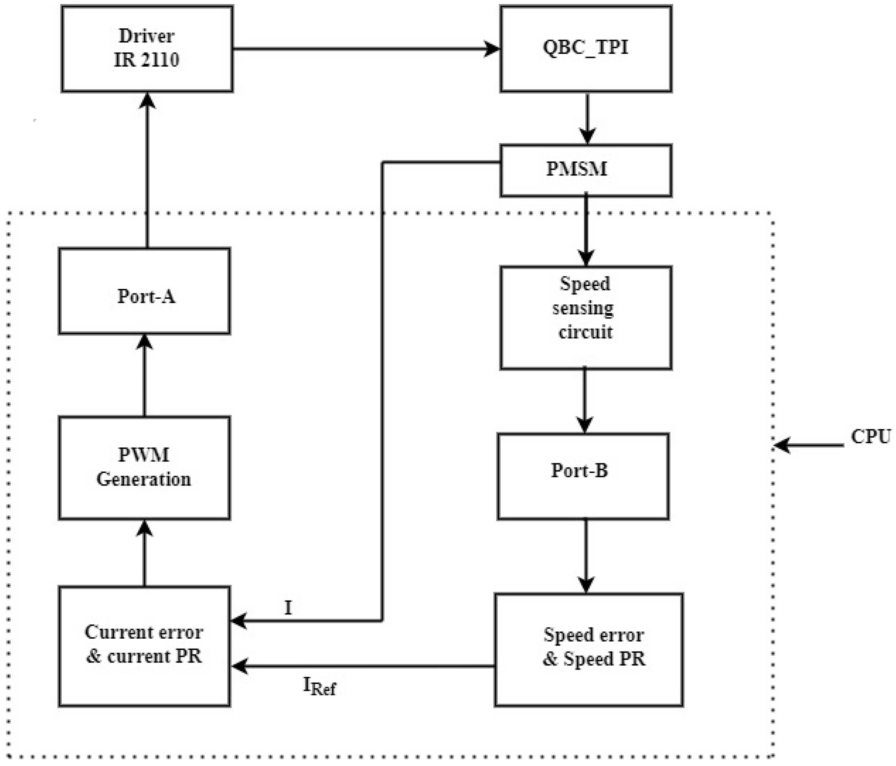
- Switched capacitor three-phase quadratic boost converter for the PMSM drive is designed.
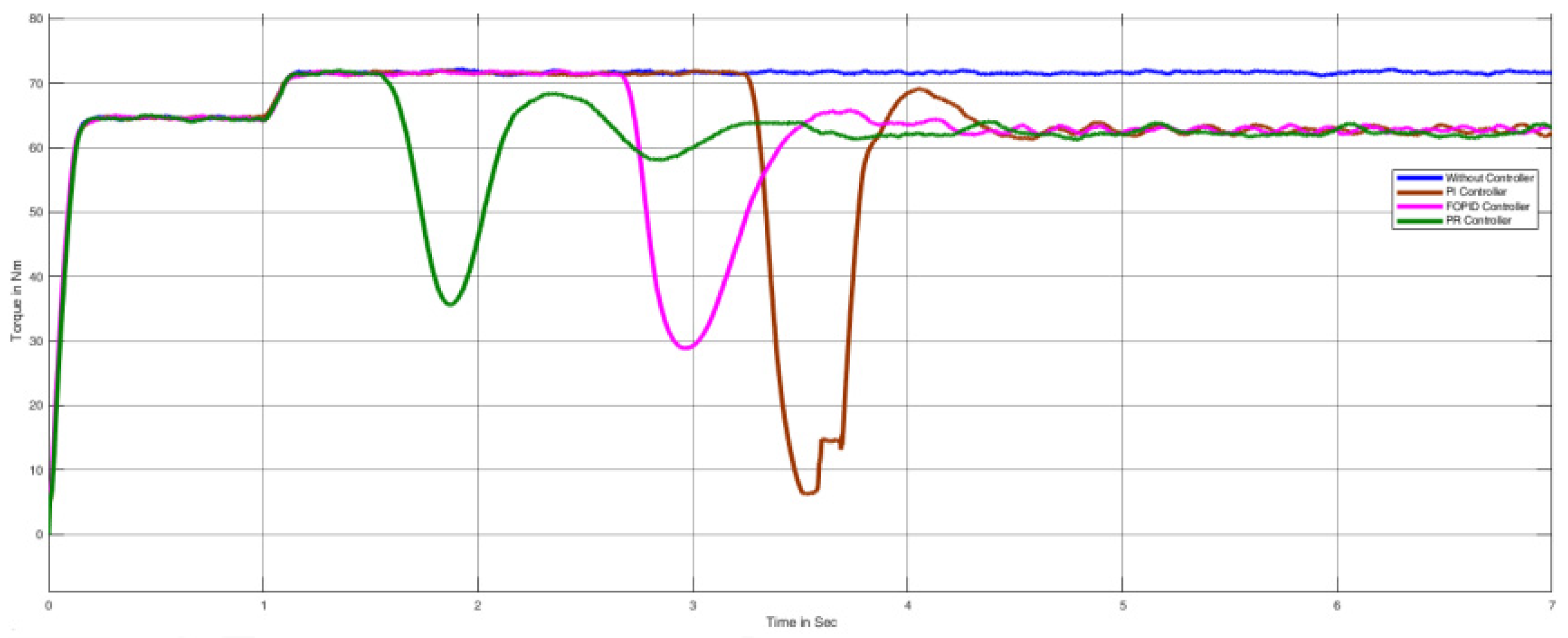
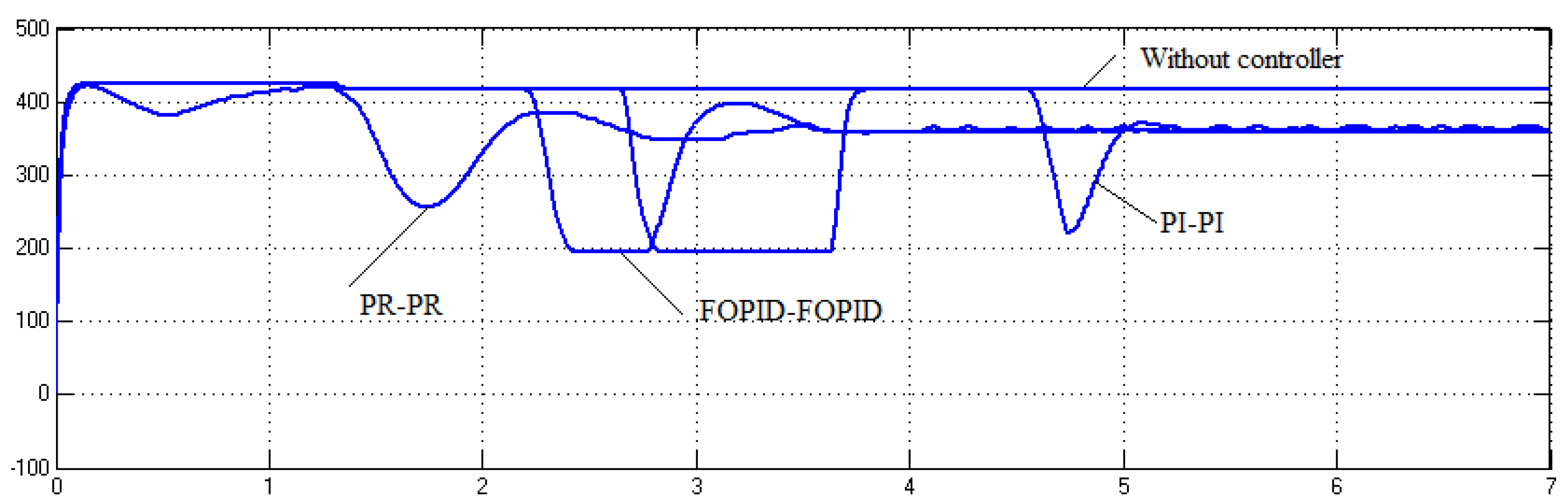
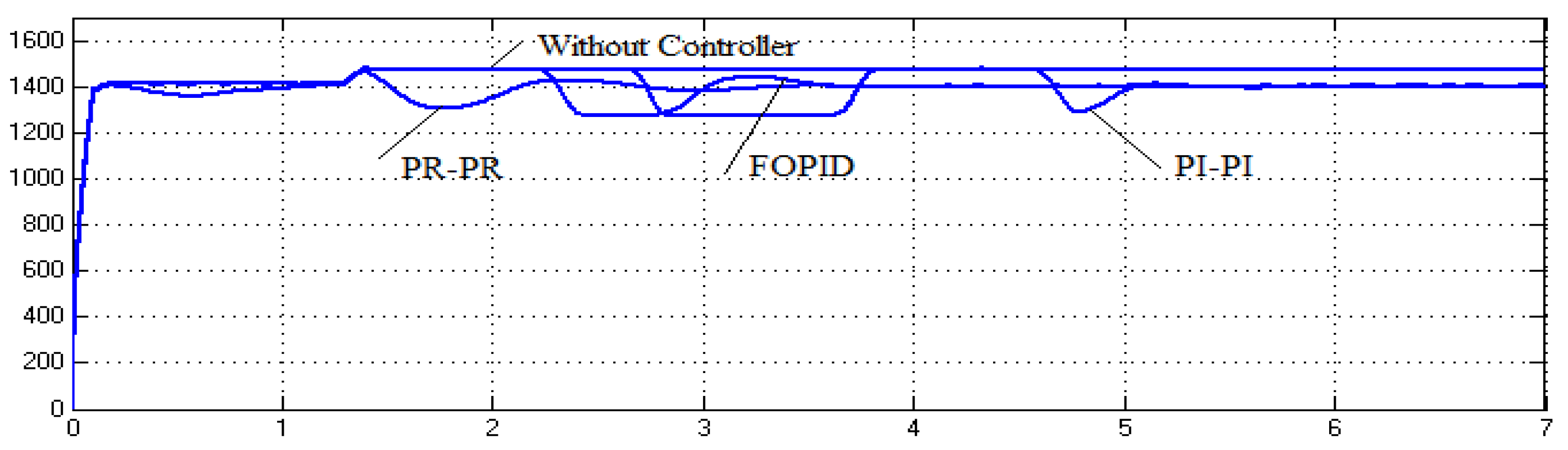
- Integrated PMSM-based PI-PI, FOPID-FOPID, and PR-PR controllers are developed using the SIMULINK platform.
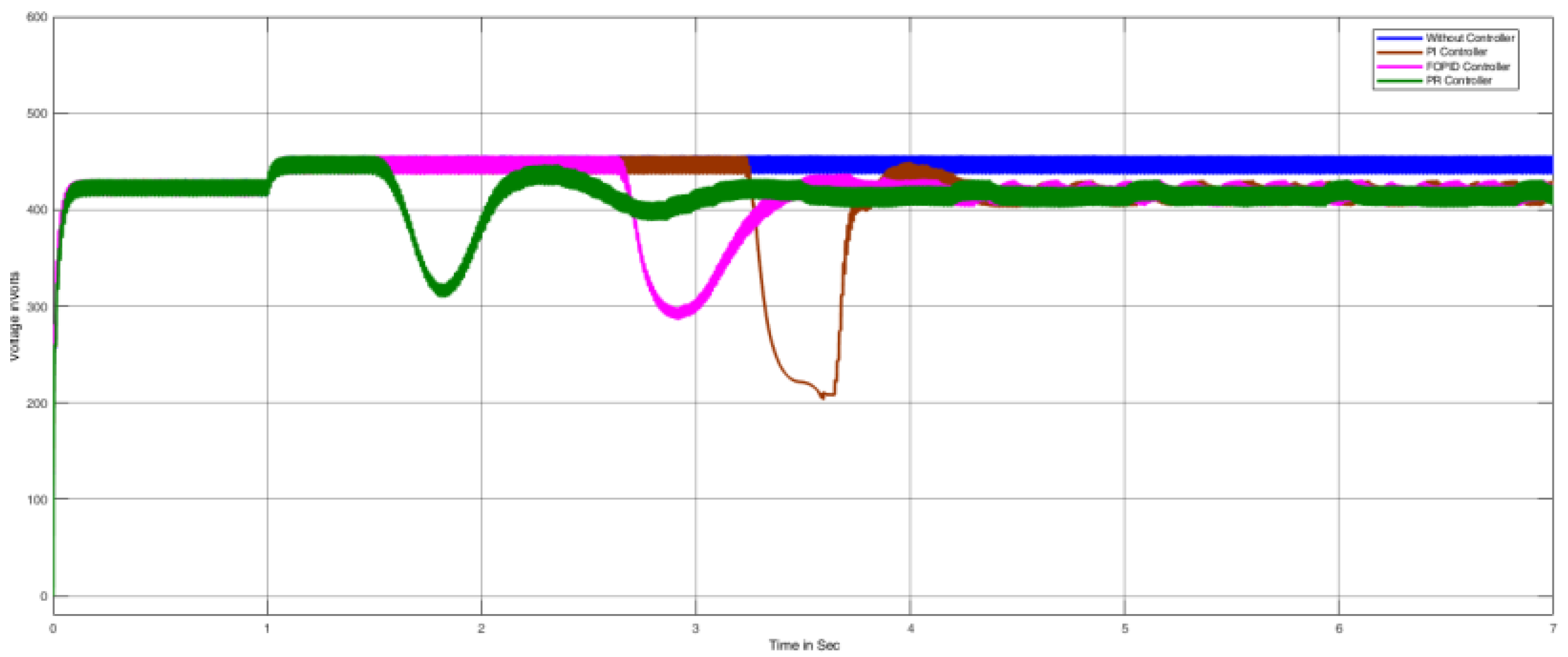
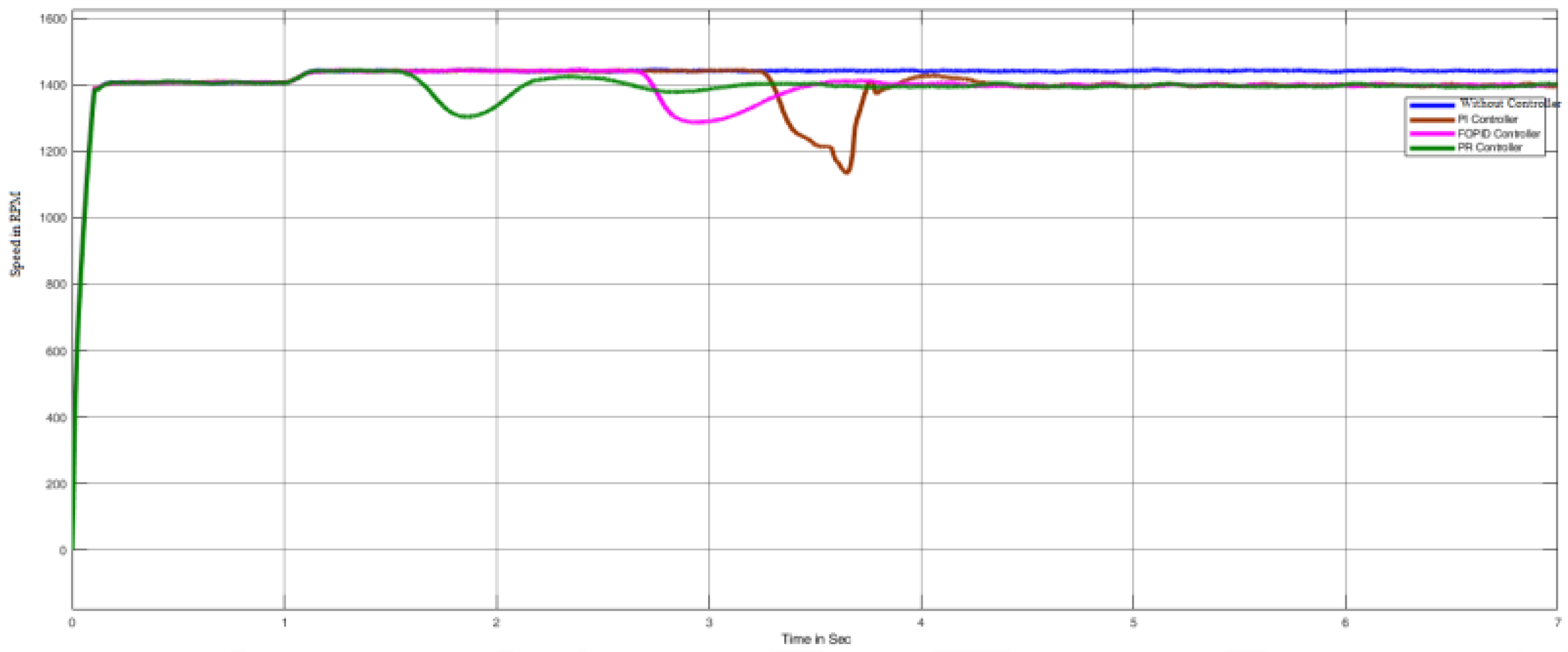
- The characteristic features of the proposed design are assessed, namely input voltage, the voltage across QBC, and the speed and torque of the electric motor.
- A simulation study is carried out for both open-loop and closed-loop systems.
- Illustrated the dynamic responses of the considered case’s likely time-domain parameters.
- Developed the hardware prototype of the proposed model and assessed its characteristics.
1.4. Organization of the Article
The rest of the work is organized as follows: Section 2 demonstrated the problem formulation and proposed methodology. Consequently, Section 3 exemplifies the comprehensive results and discussions of the proposed approaches. Section 4 illustrates the experimental setup of the proposed model with outcomes. Subsequently, a comparative examination is carried out between several existing methodologies in Section 5 that can validate the effectiveness of the proposed method. Lastly, conclusions are derived in Section 6 grounded on the perceived consequences.
2. Problem Formulation and Proposed Methodologies
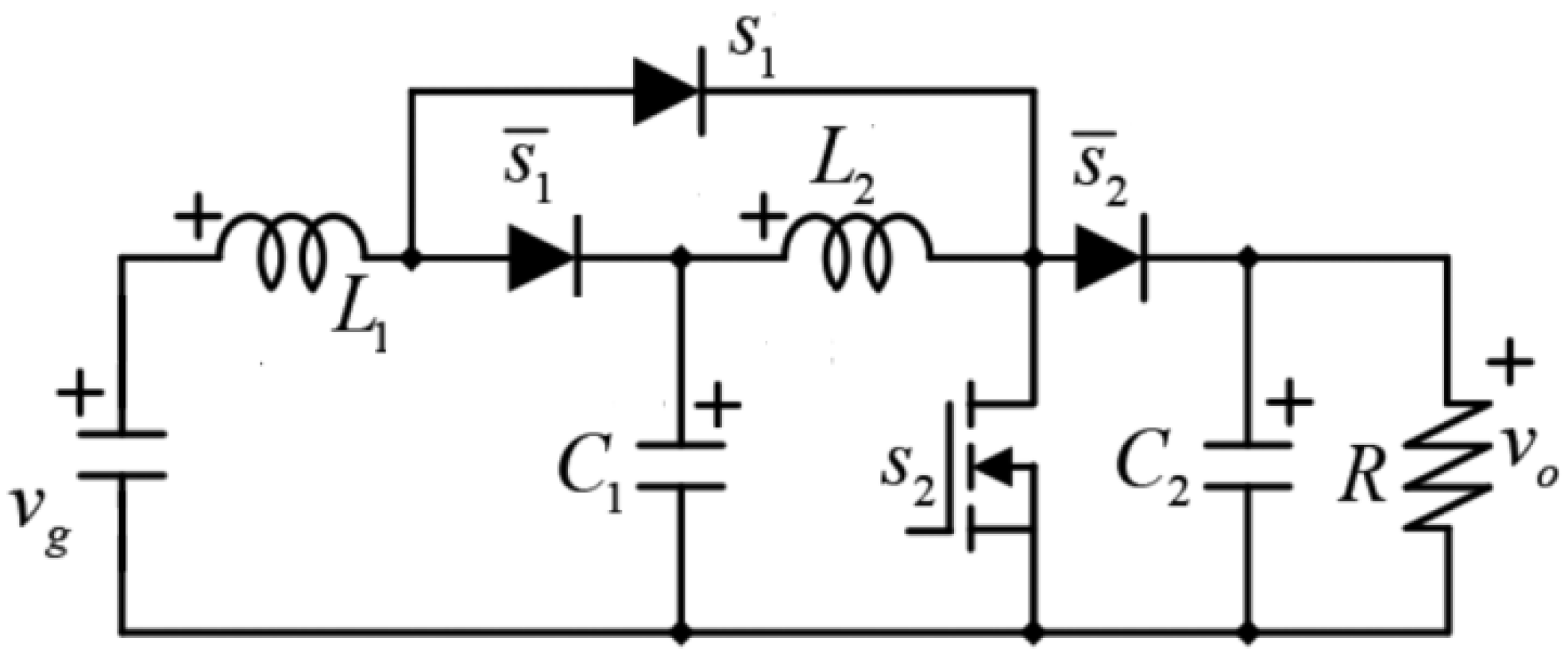
2.1. Design of QBC
In this section, the study procedure of the anticipated QBC topology is illustrated, which is depicted in Figure 1. Both transistors are commutated at a constant frequency using signals with the same duty cycle but shifted 180° between them. The diodes emphasize the complementary switching concerning transistors. The following descriptions prove how the anticipated converter and switching approach led to a substantial decrease in the energy storage of capacitors for a given output voltage ripple measurement and power rating regarding the conventional QBC [31].
Figure 1.
Proposed QBC topology.
Considering the complementarity of the switching signals by applying the traditional state averaging technique [32], the dynamic model of the proposed converter topology can be expressed. The formulation and the values of L1, L2, C1, and C2 of QBC are illustrated in Table 2.
Table 2.
Formulation and parameter values of QBC.
2.2. Proposed Methodologies
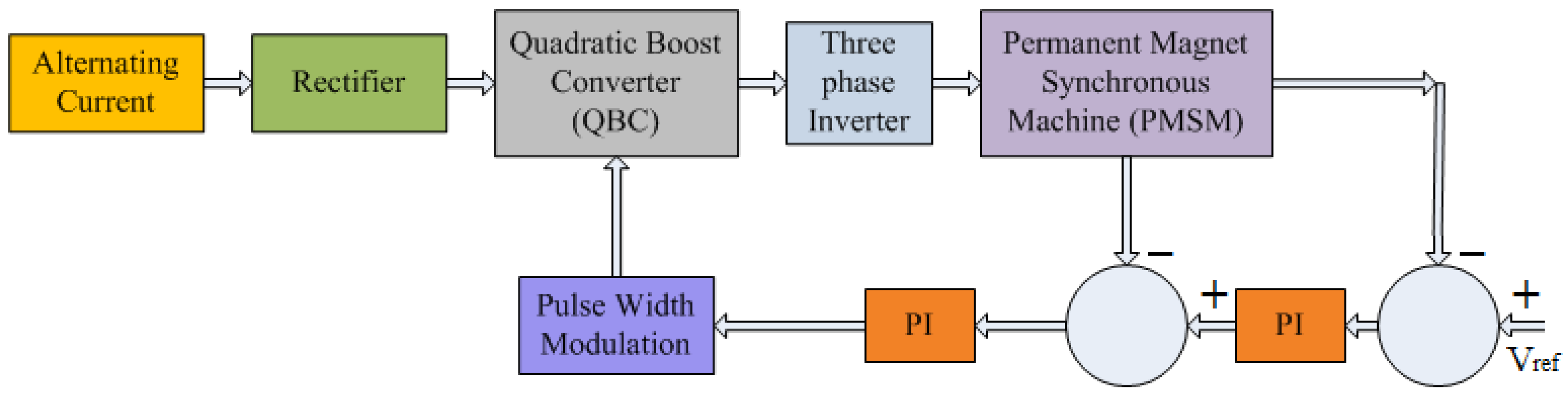
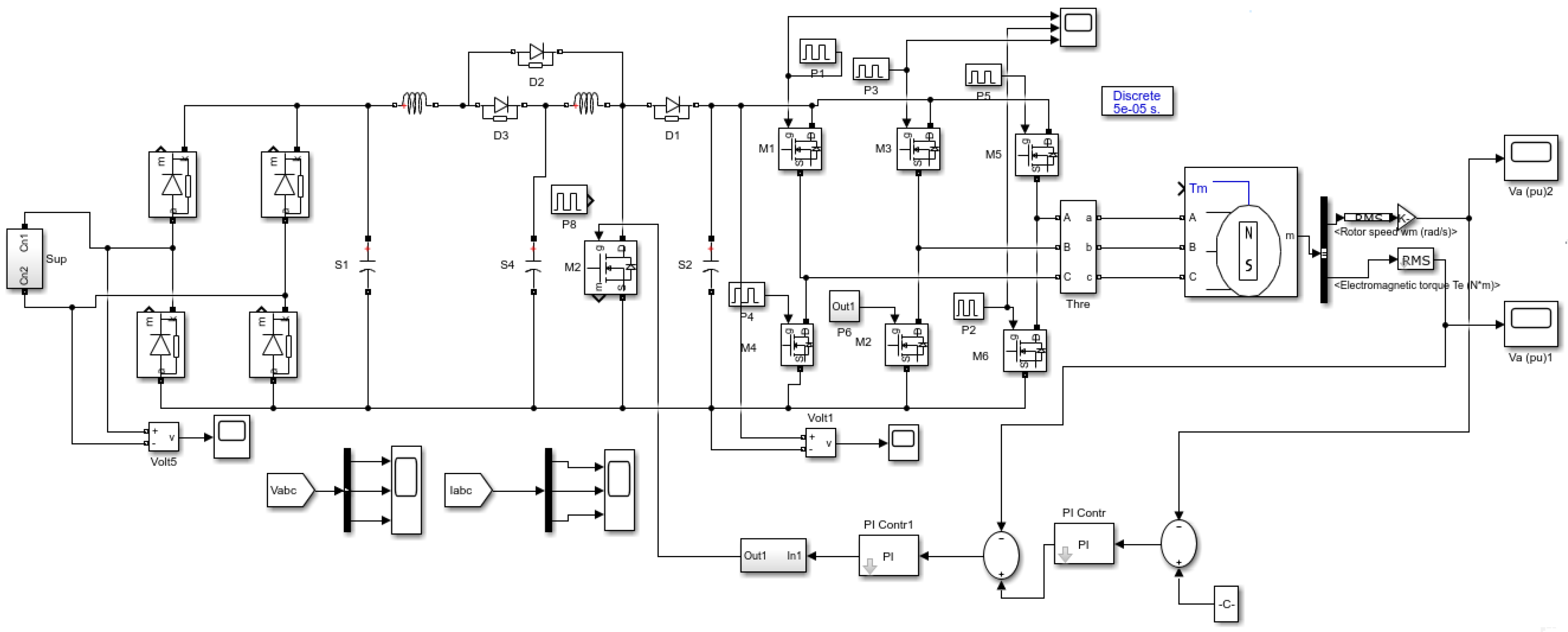
2.2.1. PI-PI Controlled QBC-TPI
The block diagram of the PI-PI controlled SC-QBC-TPI fed PMSM system is shown in Figure 2. QBC steps up the DC input to a rate prerequisite by the load even with a lesser duty ratio associated with the DC arrangement employing a boost converter and the output of QBC is inverted employing TPI. Then, the speed of the PMSM motor is detected, and it is related to the reference speed of the machine. Further, the speed error is set to the speed of the PI controller. Then, the output of the PI controller is compared with the actual current to get a current error. The current error is given to the current PI controller. The output of the current PI controller is applied to a comparator to yield an updated pulse signal to MOSFET switches.
Figure 2.
Block-Diagram of PI-PI controlled QBC-TPI fed PMSM drive system.
The output of the PI-PI controller is as follows:
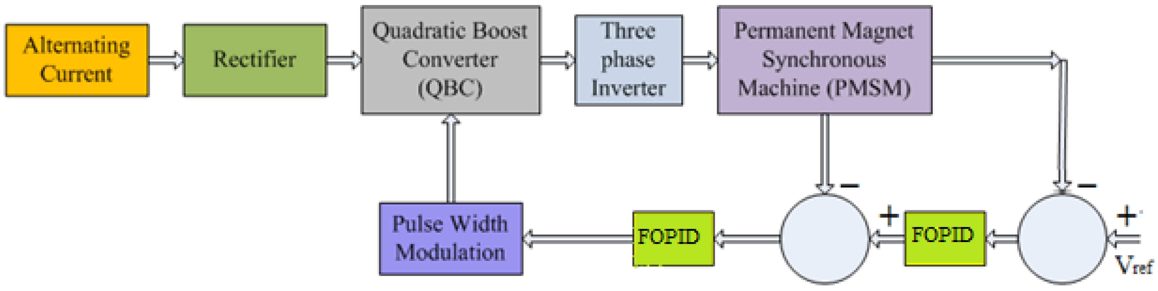
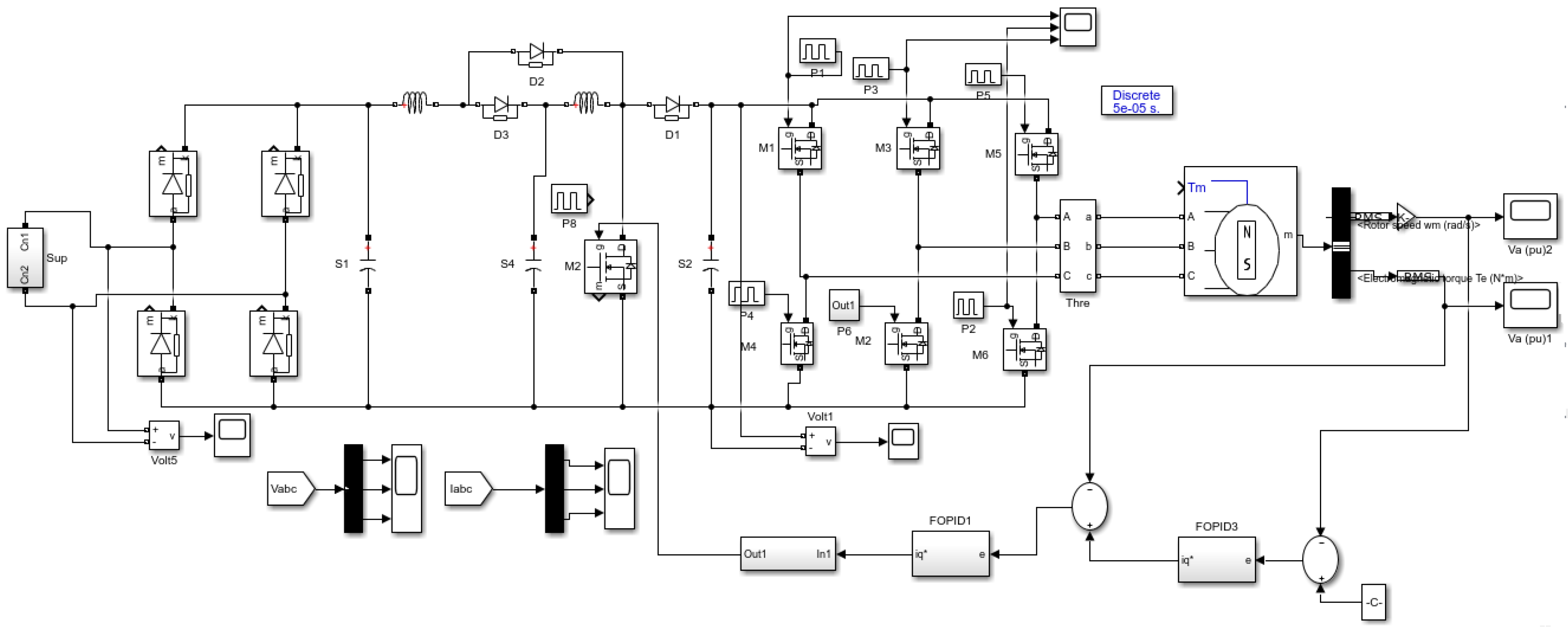
2.2.2. FOPID-FOPID Controlled QBC-TPI
The block diagram of the FOPID-FOPID controlled SC-QBC-TPI fed PMSM system is shown in Figure 3. PI-PI controller speeds and current errors are processed by speed FOPID and torque FOPID controllers, respectively. The processed signal is modulated and given to QBC. From which regulated voltage is obtained, and this is fed to the inverter to improve the response of PMSM.
Figure 3.
Block-Diagram of FOPID-FOPID controlled QBC-TPI fed PMSM drive system.
The output of the FOPID-FOPID controller is as follows:
Proportional, integral, and derivative gains of the FOPID controller are respectively. Integral and derivate fractional orders are , respectively.
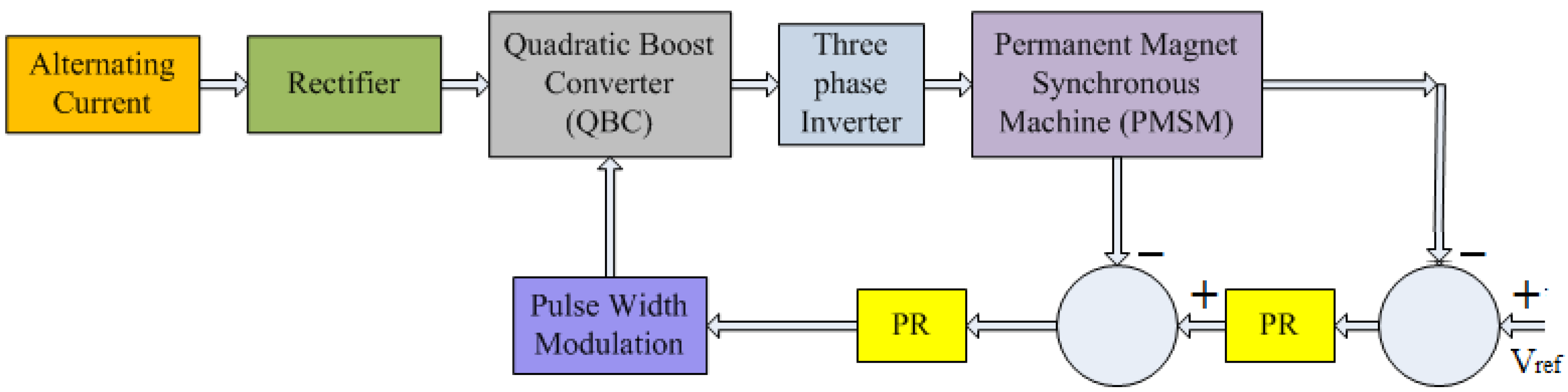
2.2.3. PR-PR Controlled QBC-TPI
The block diagram of the PR-PR controlled SC-QBC-TPI fed PMSM system is shown in Figure 4. Similar to the PI-PI and FOPID-FOPID controlled QBC-TPI, the input and respective output values for individual blocks are assessed. Particularly, QBC steps up the DC input to a rate required by the load even with a lesser duty ratio associated with the DC arrangement employing a boost converter, and the output of QBC is inverted utilizing TPI as given in PI-PI, FOPID-FOPID control approaches. Furthermore, the speed error is set to the speed of the PR controller. Then, the output of the PR controller is compared with the actual current to get a current error. The current error is given to the current PR controller.
Figure 4.
Block Diagram of PR-PR controlled QBC-TPI fed PMSM drive system.
Generally, this model utilizes PR control to diminish steady-state errors up to zero. Subsequently, it acts as a capable controller to generate sinusoidal signs. At this point, this framework utilizes an approach to sinusoidal signs/AC controllers. The exchange capacity of the PR-PR controller can be defined as follows:
where is a proportional constant and is a resonant constant.
The output voltage of QBC is shown below.
The output voltage of TPI is shown below.
The equations of PMSM are as follows:
The developed torque is given by
The mechanical Torque equation is
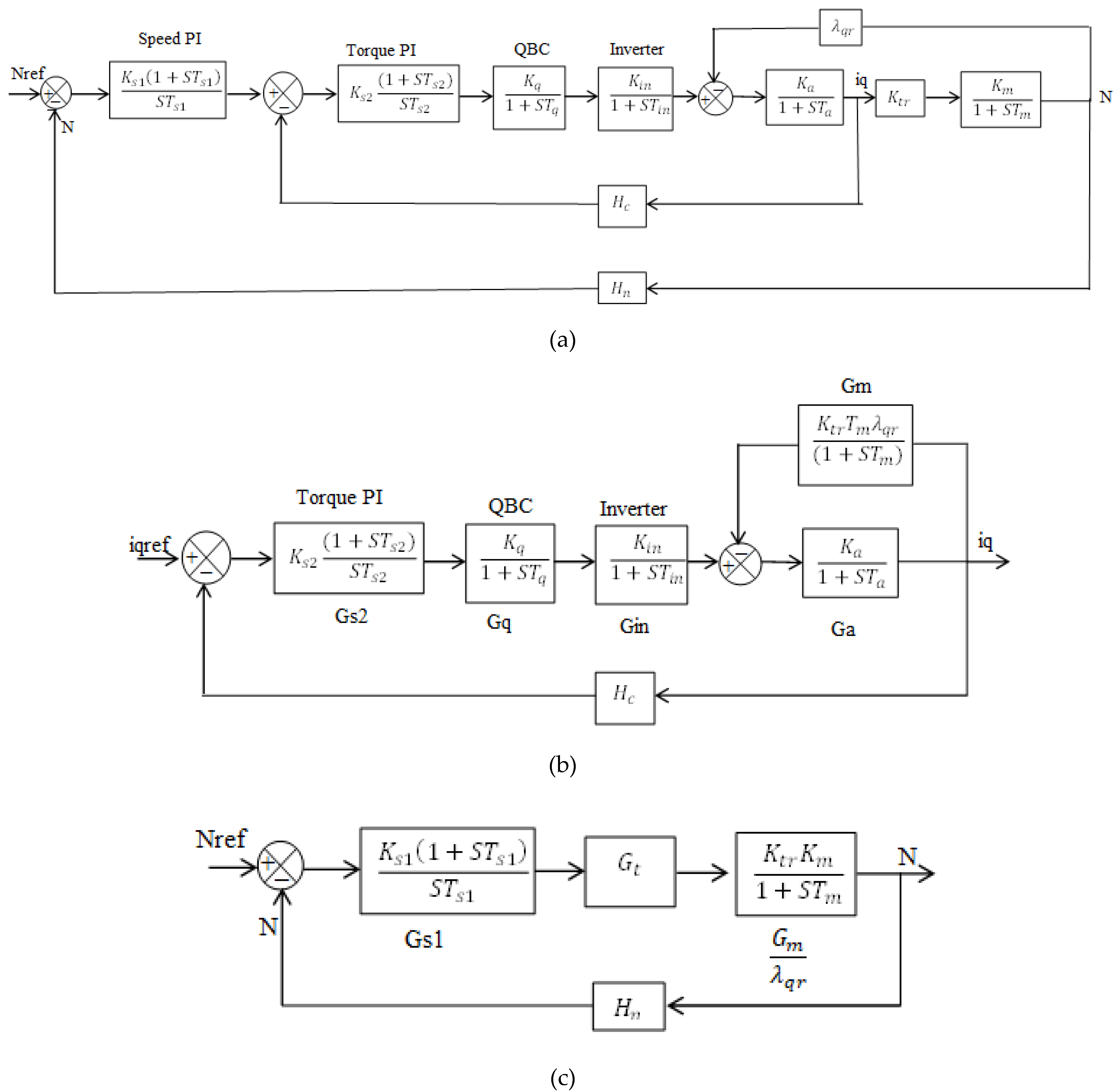
3. Mathematical Model of Proposed System
PI-PI Controller
Figure 5 shows the developed model of the control system block diagram of the PI-PI controller. The design of the torque and speed controller is important for analyzing the stability of the drive.
Figure 5.
(a) Control Block of PI-PI controller, (b) Torque Control Block of PI-PI controller, and (c) Speed Control Block of PI-PI controller.
In the inverter block, Kin is inverter gain, whereas Tin is time constant.
Vdc, Vc is dc link voltage, control voltage, and fs is the switching frequency of the inverter.
In QBC Kq, Tq are gain and time constant.
D is the Duty ratio of QBC.
In motor Ka, Km, Ta, and Tm are the gains, electrical, and mechanical time constants.
Rs, Lq Stator resistance and q axis inductance of the motor.
J, B Moment of inertia and frictional coefficient of the motor.
λqr Flux linkages of the rotor, Ktr Torque constant.
Hc, Hn current and speed feedback gain, respectively.
The transfer function of the torque loop constitutes the following:
This torque loop transfer function Gt is used to design the speed controller as follows.
The transfer function of the speed controller is
By negating zero and adding poles to the speed command path, the overshoot can be reduced. The FOPID-FOPID and PR-PR poles are inserted in a series with the reference speed to achieve the stability of the system.
4. Results and Discussions
4.1. Open loop SC-QBC-TPI Fed PMSM with Source Disturbance
The simulation parameters of SC-QBC-TPI fed PMSM are given in Table 3. Based on the parameters, the circuits are designed, and the simulation is carried out for an Open Loop state with source disturbance, as illustrated in Figure 6. From the observed results, the input voltage of the proposed scheme is demarcated in Figure 7, and it shows a scale of about 210 V. Furthermore, the voltage across the QBC with source disturbance is illustrated in this Figure which shows a value of about 450 V. Consequently, the voltage across the motor load with source disturbance is logged as 490 V (Figure 8). Then, the motor speed with source disturbance is recorded in Figure 9 which shows a notable value of about 1400 RPM. Lastly, motor torque with source disturbances was observed to be 73 N-m, as illustrated in Figure 10.
Table 3.
Simulation parameters.
Figure 6.
Open Loop SC-QBC-TPI fed PMSM with source disturbance.
Figure 7.
Input Voltages (Volts).
Figure 8.
Voltage across QBC with distribution (Volts).
Figure 9.
Motor speeds with source disturbance (RPM).
Figure 10.
Motor torques with source disturbance (N-m).
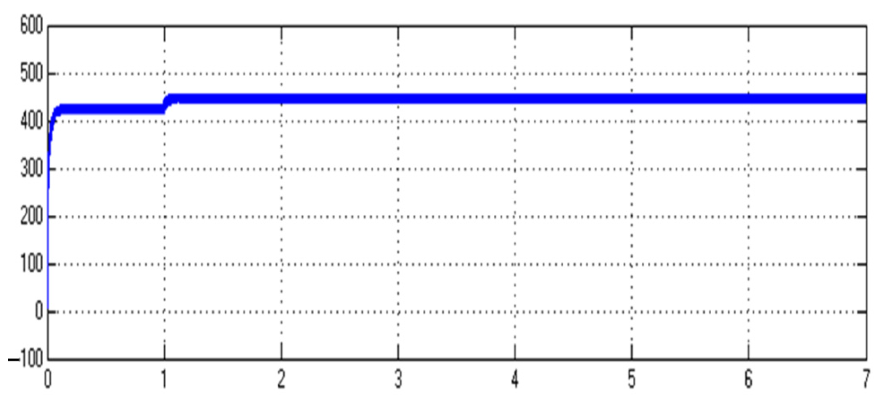
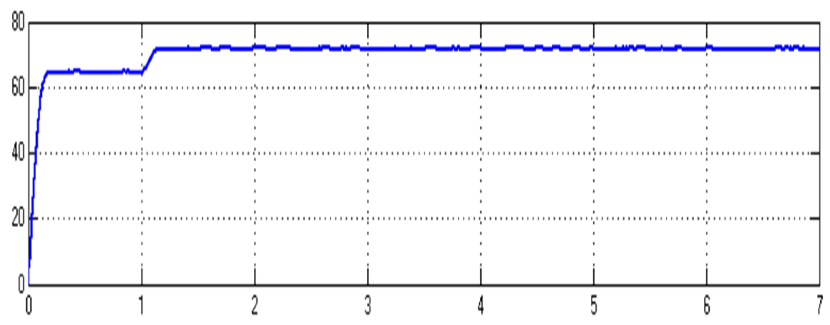
4.2. Closed Loop SC-QBC-TPI Fed PMSM
Based on the loop design, a closed loop SC-QBC-TPI fed PMSM with PI-PI and FOPID-FOPID is designed in MATLAB platform as represented in Figure 11 and Figure 12, respectively. Similarly, the closed loop SC-QBC-TPI fed PMSM with PR-PR also developed, as illustrated in Figure 13. A sudden eternal source disturbance is applied at time t = 1 s. Then, the Voltages across QBC with and without PI-PI, FOPID-FOPID, and PR-PR are derived and illustrated in Figure 14. Significantly, a step change is observed in their magnitudes from 420 V to 480 V in the voltage across QBC without controller configurations. Particularly, adopting the PI-PI, FOPID-FOPID controller, the voltage across QBC initially declines and then upsurges to 420 V. By using PR-PR, the voltage across QBC declines initially and rises to 420 V but is found to be stable.
Figure 11.
Closed loop SC-QBC-TPI fed PMSM with PI-PI CONTROLLER.
Figure 12.
Closed Loop SC-QBC-TPI Fed PMSM with FOPID-FOPID Controller.
Figure 13.
Closed Loop SC-QBC-TPI Fed PMSM with PR-PR Controller.
Figure 14.
Motor voltages with PI-PI, FOPID-FOPID, and PR-PR (Volts).
Similar to the voltage, motor speed shows symmetrical trends comparing with and without PI-PI, FOPID-FOPID, and PR-PR controller, and the respective illustration is depicted in Figure 15. Notably, a step change is detected in their magnitudes from 1400 RPM to 1500 RPM without controller approaches. In the speed waveform, after the source of disturbance, speed increases by about 40 RPM with PI-PI, it increases by 35 RPM with the FOPID-FOPID controller and by 30 RPM with the PR-PR controller. Even though the speed overshoots by about 30 RPM, it takes less time to reach its speed of 1420 RPM. Elaborately, motor speed initially declines and then inclines to 1420 RPM adapting the PI-PI. Similarly, the PR-PR controller shows the same trends but shows a magnitude of 1420 RPM with more stable characteristics.
Figure 15.
Motor speeds with PI-PI, FOPID-FOPID, and PR-PR (RPM).
Further, motor torque characteristics are assessed for different control strategies and the complete illustration is shown in Figure 16. It is observed that the small fluctuations are observed in their magnitudes against different controllers significantly from 62 N-m to 72 N-m in motor torque, which duplicates the behavior of voltage and speed characteristics. By using PI-PI in motor torque, the value initially declines and upsurges to 61 N-m. Compared to the PI controller, FOPID has two more adjustable parameters, such as integral and differential order. Therefore, applied to the PMSM drive system, it shows better control performance than PI. From the torque waveform, it can be observed that less undershoot and a steady value of 61 N-m can be reached in a smaller sec, whereas PI has a large undershoot and more time to reach a steady state by using PR-PR in motor torque (the value is 61 N-m and it is stable). Based on the observed results, it can be concluded that the magnitudes of PR-PR controllers show less compared with PI-PI, and FOPID-FOPID controllers.
Figure 16.
Motor torques with PI-PI, FOPID-FOPID, and PR-PR (N-m).
4.3. Closed Loop SC-QBC-TPI Fed PMSM with Load
The simulated responses of PI-PI, FOPID-FOPID, and PR-PR under loaded conditions are depicted in Figure 17, Figure 18 and Figure 19, in which the waveforms represent voltage across QBC, speed, and torque, respectively. To verify the robustness of the proposed methods, the simulations are executed for loaded conditions. A sudden external source is applied at time t = 1 s.
Figure 17.
Voltage across QBC of PI-PI, FOPID-FOPID, and PR-PR with load.
Figure 18.
Motor speeds of PI-PI, FOPID-FOPID, and PR-PR with load.
Figure 19.
Motor torques of PI-PI, FOPID-FOPID, and PR-PR with load.
From Voltages across QBC, it can be observed that it varies from 400 to 420 without the controller. In PI-PI and FOPID-FOPID controllers, the QBC voltage is 380 V. The voltage response of PI-PI is not satisfied compared to the FOPID-FOPID controller because it has an oscillatory signal for a long time. When using PR-PR, it initially decreased and then quickly settled at 380 V.
From the speed waveform, we can observe a step change in speed from 1400 RPM to 1500 RPM in an open loop system. Through the PI-PI and FOPID-FOPID in motor speed, the value at the initial stage increases and surges to 1420 RPM. Use of PR-PR motor speed helps to attain a stable value of 1420 RPM. Figure 19 depicts a step change in torque noticed from 65 N-m to 94 N-m without a controller. While employing PI-PI, FOPID-FOPID in the motor torque, the value first increases and surges to 97 N-m. It is found that the use of PR-PR in motor torque leads to a stable value of 97 N-m. The speed and torque response of PR-PR-QBC-TPI-PMSM is found to be very smooth compared to PI-PI and FOPID-FOPID controllers.
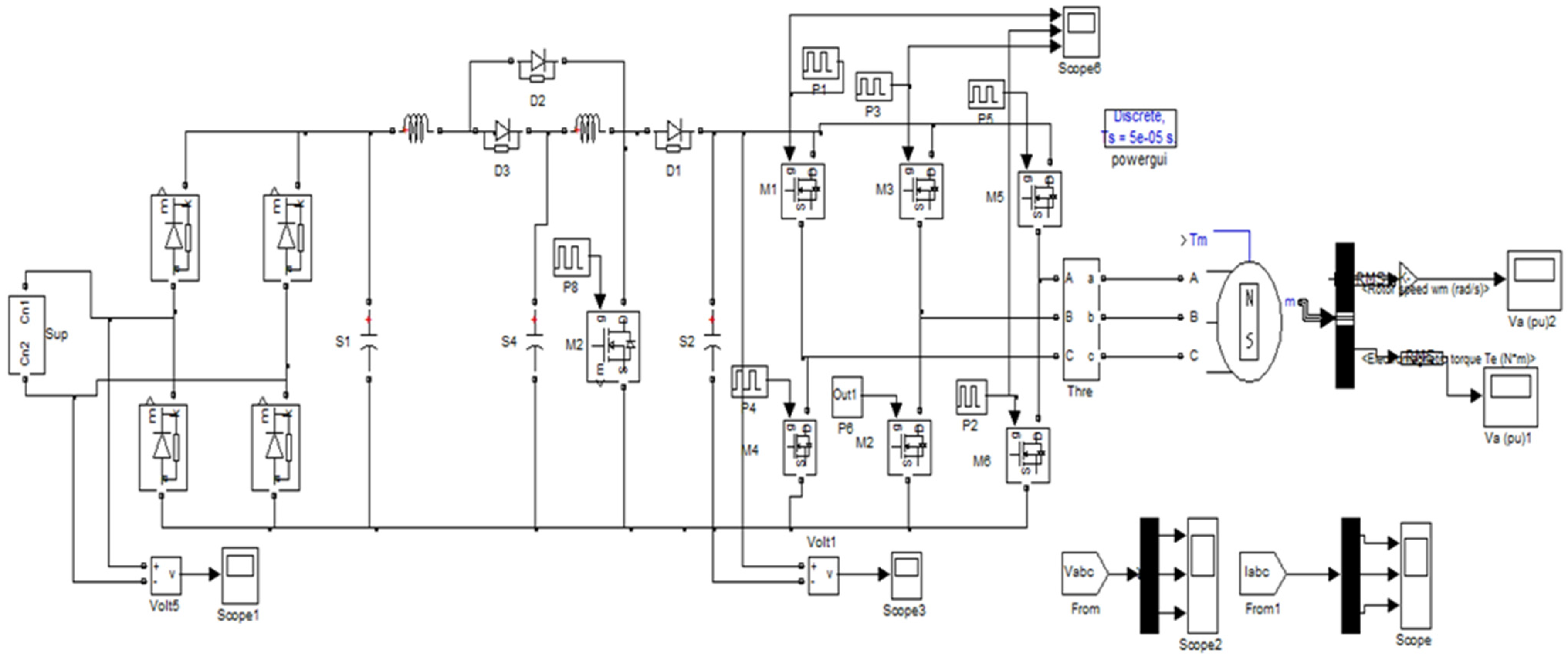
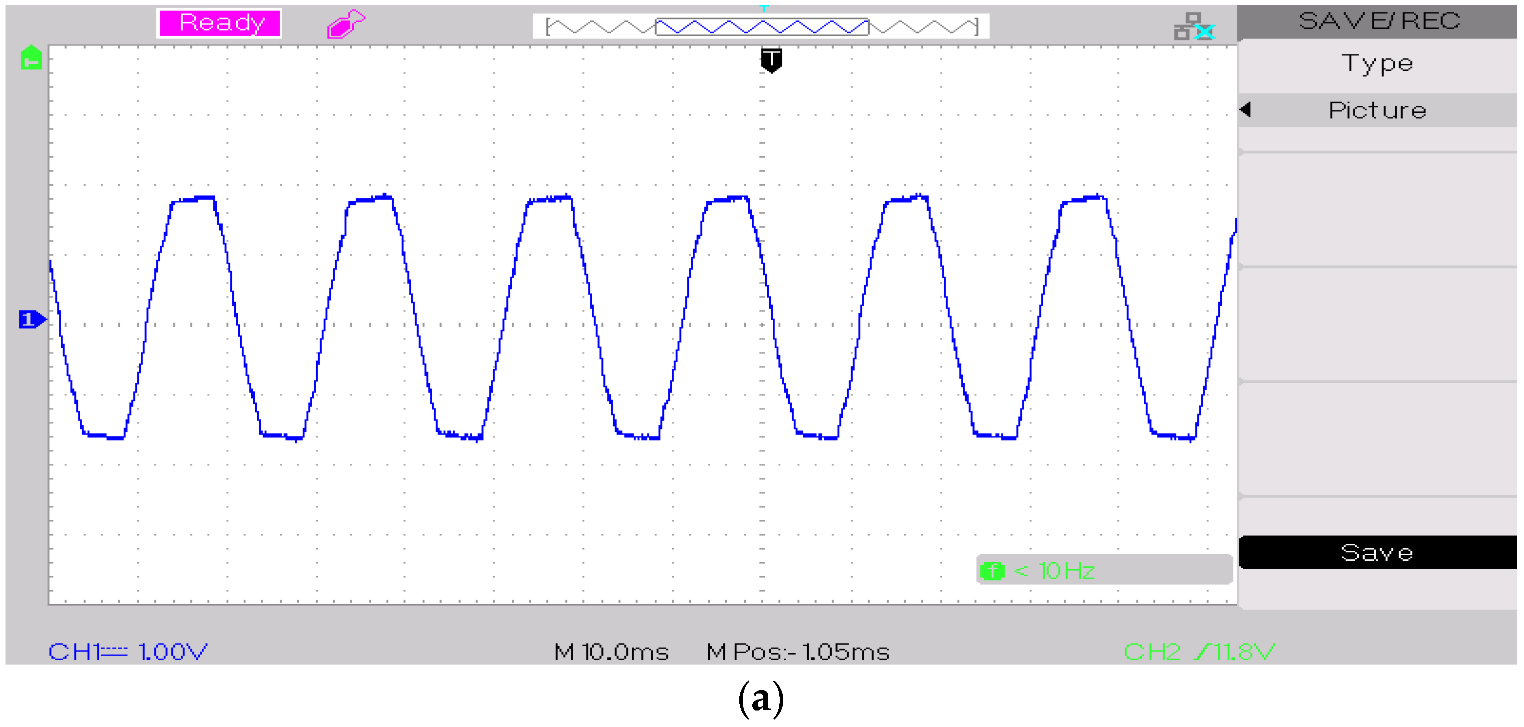
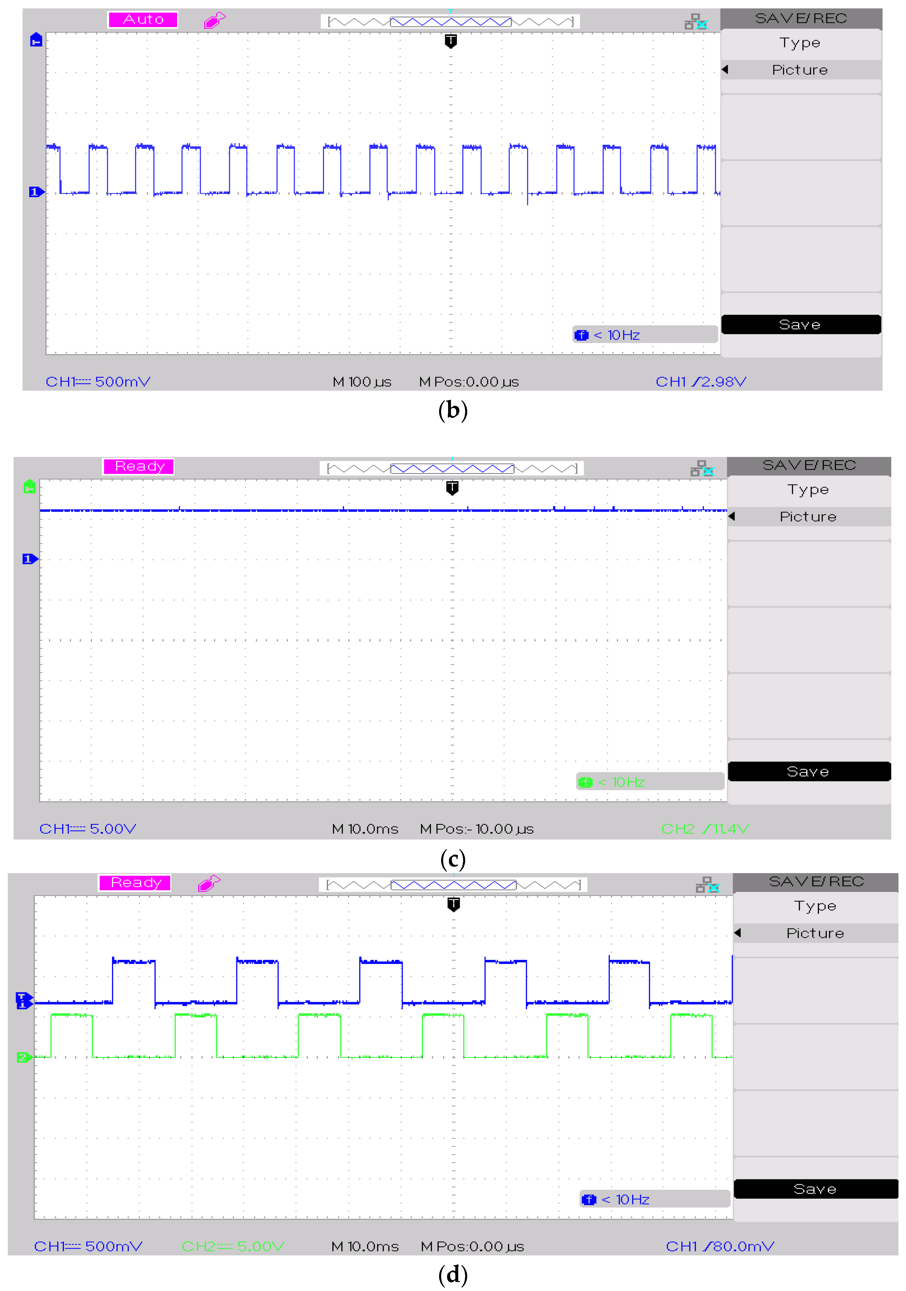
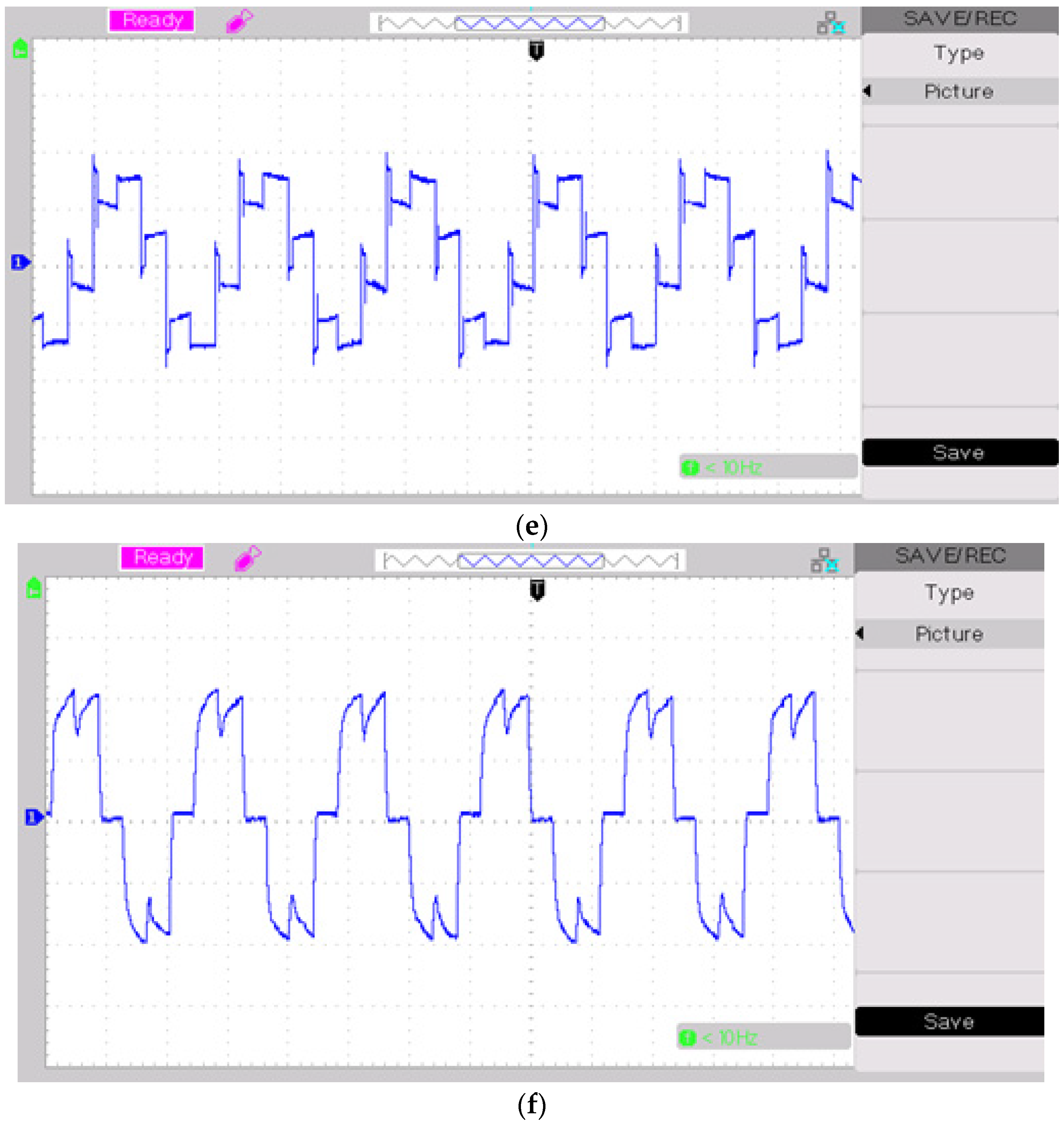
5. Experimental Module of SC-QBC-TPI-PMSM
The experimental design of the SC-QBC-TPI fed with a permanent magnet synchronous motor (PMSM) is shown in Figure 20. It comprises the rectifier, QBC, transformer, driver circuit, and PMSM load. The switching pulse for S1 of QBC is generated using a separate algorithm, as illustrated in Figure 21. Its speed error is given to the Port-B of PIC-16 F84, and the current reference is calculated and applied to the PR/PI block. Then, the output of the current error block is fed to generate pulses for QBC and TPI; pulses generated by port A are amplified using IR2110.
Figure 20.
Hardware design of QBC-PMSM.
Figure 21.
Block diagram of control circuit for QBC-TPI-PMSM.
The outputs are observed considering various parameters such as the input voltage, the switching pulse of QBC, the voltage across QBC, the switching pulse of the inverter, the voltage across the motor, and the current through the motor (Figure 22).


Figure 22.
Hardware results of the SC-QBC-TPI-PMSM. (a) Input voltage of QBC-PMSM. (b) Switching pulse for S1 of QBC. (c) Switching pulse of inverter. (d) Voltage across QBC. (e) Voltage across the motor. (f) Current through motor.
The above results are the representation of the proposed SC-QBC-TPI fed with PMSM. The observed results show an actual characteristic of the proposed approach against disturbance and offer a better output voltage of about 412 V, which is relatively close to the simulated voltage of the inverter. From the observed results, it can be seen that dual PR-controlled SC-QBC-TPI-PMSM can achieve better results with improved responses.
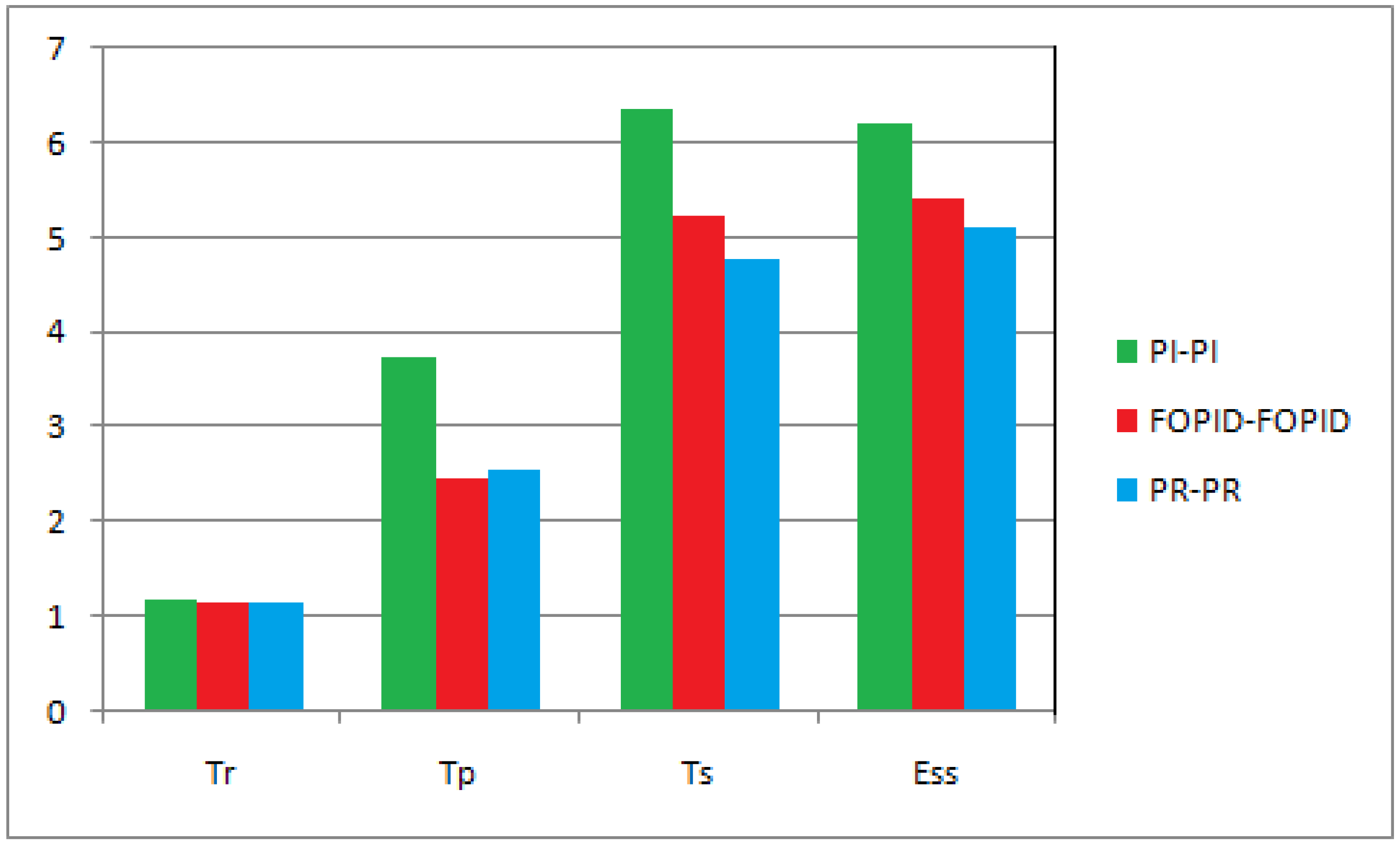
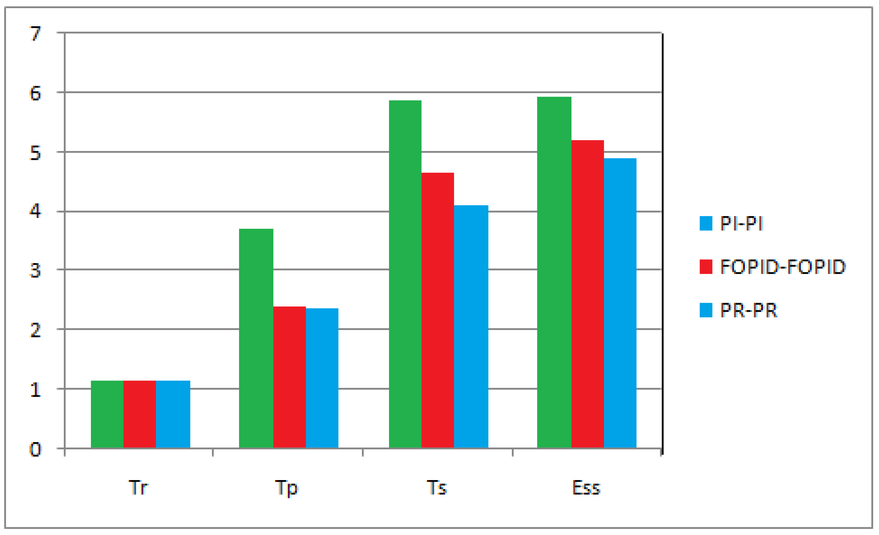
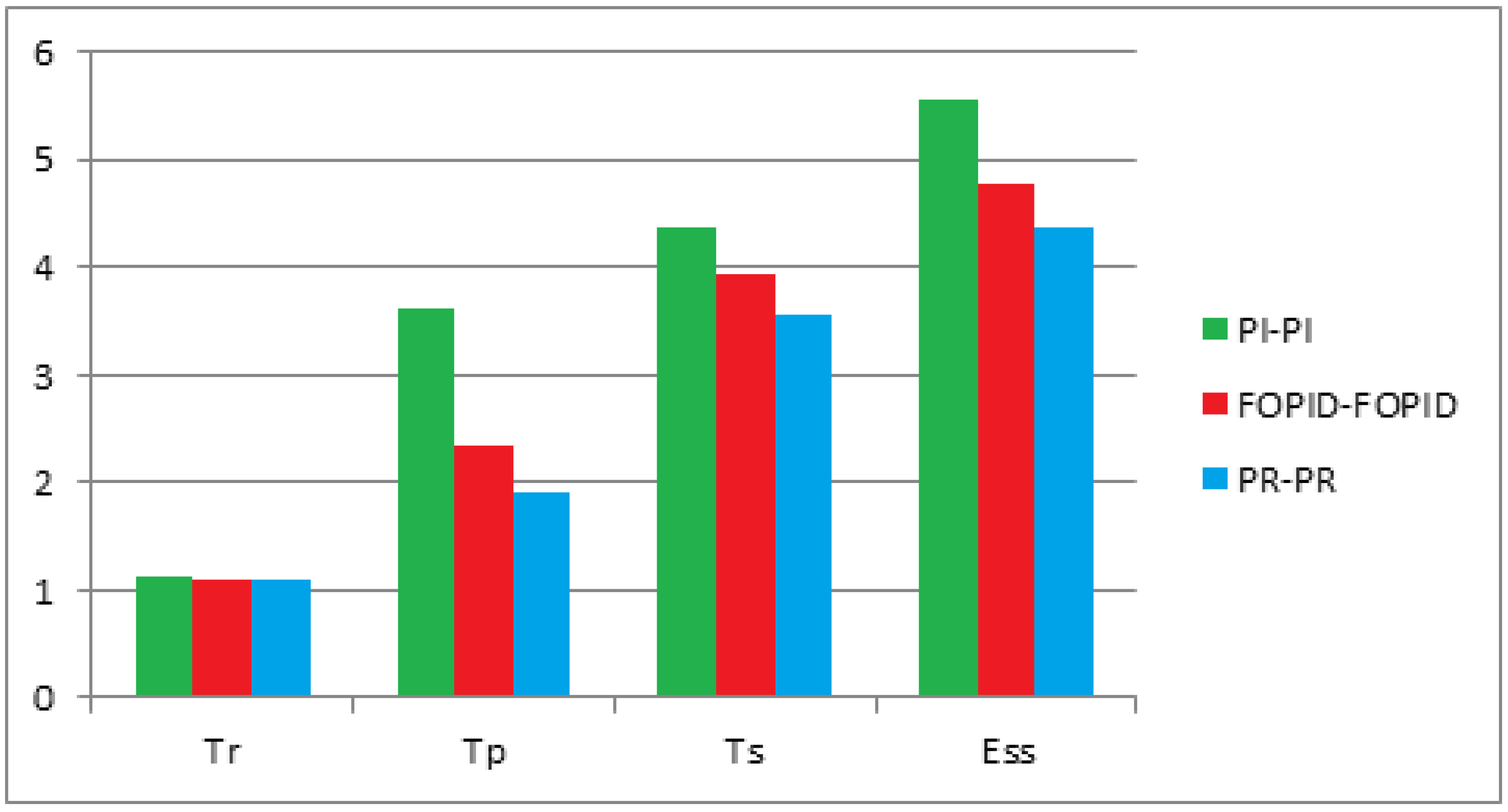
6. Comparative Analysis
The assessment of the time of the domain parameters referring to the Nref-1450 RPM utilizing PI-PI, FOPID-FOPID, and PR-PR is derived and depicted in Figure 23. Compared with the PI-PI and FOPID-FOPID controllers, the rise time (Ts) of the PR-PR controller is reduced from 1.17 s to 1.15 s; the peak time (Tp) is declined from 3.70 s to 2.38 s; the settling time (Ts) is reduced from 5.86 s to 4.12 s; the steady-state error (Ess) is condensed from 5.93 s to 4.89 s. Similar trends are observed for other reference speeds, notably Nref-1475 RPM and Nref-1400 RPM, and the respective comparative illustrations are shown in Figure 24 and Figure 25, respectively.
Figure 23.
Comparison of time domain parameters (Nref-1450 RPM) using PI-PI and PR-PR.
Figure 24.
Comparison of time domain parameters (Nref-1475 RPM) using PI-PI and PR-PR.
Figure 25.
Comparison of time domain parameters (Nref-1400 RPM) using PI-PI, FOPID-FOPID, and PR-PR.
The assessment of the time domain parameters referring to the various loads utilizing PI-PI, FOPID-FOPID, and PR-PR is derived and depicted in Table 4. The motor is operated at 1400 RPM, and then the source of disturbance is applied to check the disturbance rejection capability of the proposed scheme. Better performance is attained at 1.2 N-m, and there is a significant reduction obtained at 1.4 N-m by using PR-PR. At a 1.3 N-m load, there is a great improvement in time responses compared to above (1.2 N-m) and below (1.4 N-m) loaded conditions. By using the PR-PR controller, enhanced rise time, peak time, settling time, and steady-state errors were achieved. Due to its quick torque response, the motor speed quickly returns to its initial speed. Hence, it is evident that the dynamic and steady-state response gets enhanced with PR-PR controller-based TPI-PMSMD.
Table 4.
Comparison of Time domain parameters in various load conditions.
It is also observed that the simulated output and hardware results are closely related to the least error percentage of 1.9%. The comprehensive comparative study of simulation and hardware is illustrated in Table 5. The hardware results of the inverter output voltage are less than the simulated value due to drops in devices and chokes.
Table 5.
Comparison of simulation and hardware results.
Consolidating all the inferences from the simulated and hardware outcomes and comparative study, it is perceived that the dual mode PR-PR controller for SC-QBC-TPI offers better results considering the results of the input voltage, the voltage across QBC, the output voltage of the inverter, and the load voltage against the injection of disturbances. This approach can be effectively used for the electric vehicle application due to the frequent disturbances that appeared in the power train of the vehicle. It is also observed that the response speed of the PR-PR controller shows better than that which can be effectively utilized for the enhancement of the power flow transfer in electric vehicle propulsion.
7. Conclusions
In this paper, dual-mode PR-PR and PI-PI controllers are analyzed and employed in the QBC-based TPI-fed PMSM on the SIMULINK platform. The observed results are assessed using simulated waveforms. Based on the outcomes, it is found that the performance of PR-PR controlled SC-QBC-TPI fed PMSM shows superior results compared with the PI-PI model. The main contribution of the paper is to improve the dynamic response of the PMSM drive using a dual-mode proportional resonant controller. The robustness of SC-QBC-TPI is improved since speed and torque are brought back to a normal value after the increase in input voltage. This paper has proposed different control strategies for SC-QBC-TPI-fed PMSM Drives. PR is an alternative to PI and FOPID, and it is also a general philosophy for controlling the drives at different speeds of operation. It can be seen from the speed waveform the controllers differ greatly from each other. PI has limited gain, and PR has infinite gain, due to this gain, PR tracks the speed within two seconds, whereas the other controller takes more than two seconds. When controlled with a PI, FOPID controller, there are more steady-state errors, proving that the PI and FOPID model is not accurate even when compared with PR. Compared with the PI and FOPID controller, there is more flexibility in tuning and high disturbance rejection, so it takes a smaller amount of time to reach a steady state.
Significantly, the experimental setup shows improved parameters in the PR-PR control strategy likely input voltage of QBC, the switching pulse of QBC and the inverter, the voltage across QBC, the voltage across the motor, and the current through PMSM. Furthermore, the time-domain parameters are assessed, and it is found that the PR-PR provides better transient and steady-state performance. The PR-PR controller has the lowest rise time (Tr) of 1.15 s, peak time (Tp) of 2.38 s, settling time (Ts) of 4.12 s, and steady-state errors (Ess) of 4.89 s. It is also observed that the closed-loop SC-QBC-TPI fed PMSM with PR-PR controllers is greater than the closed-loop SC-QBC-TPI fed PMSM with PI-PI, FOPID-FOPID controllers.
In a nutshell, the proposed SC-QBC-TPI fed PMSM with a dual-mode PR-PR controller shows a higher gain and reduced response time with improved stability. Therefore, this model ensures robust dynamics against disturbances, particularly against changing voltage conditions. The proposed model can be effectively adapted for EV applications where frequent disturbances appear in the power train.
Author Contributions
Conceptualization, S.B. and A.S.; methodology, S.B. and A.S.; software, S.B. and A.S.; validation, S.B. and A.S.; formal analysis, S.B. and A.S.; investigation, S.B. and A.S.; resources, S.B. and A.S.; data curation, S.B. and A.S.; writing—original draft preparation, S.B. and A.S.; writing—review and editing, S.B. and A.S.; visualization, S.B. and A.S. All authors have read and agreed to the published version of the manuscript.
Funding
This research received no external funding.
Institutional Review Board Statement
Not applicable.
Informed Consent Statement
Not applicable.
Data Availability Statement
Not applicable.
Conflicts of Interest
The authors declare no conflict of interest.
References
- Raju, K.; Elavarasan, R.M.; Mihet-Popa, L. An Assessment of Onshore and Offshore Wind Energy Potential in India Using Moth Flame Optimization. Energies 2020, 13, 3063. [Google Scholar]
- Subramanian, S.; Sankaralingam, C.; Elavarasan, R.M.; Vijayaraghavan, R.R.; Raju, K.; Mihet-Popa, L. An Evaluation on Wind Energy Potential Using Multi-Objective Optimization-Based Non-Dominated Sorting Genetic Algorithm III. Sustainability 2021, 13, 410. [Google Scholar] [CrossRef]
- Venkatesan, C.; Kannadasan, R.; Ravikumar, D.; Loganathan, V.; Alsharif, M.H.; Choi, D.; Hong, J.; Geem, Z.W. Re-Allocation of Distributed Generations Using Available Renewable Potential Based Multi-Criterion-Multi-Objective Hybrid Technique. Sustainability 2021, 13, 13709. [Google Scholar] [CrossRef]
- Anthony, M.; Prasad, V.; Raju, K.; Alsharif, M.H.; Geem, Z.W.; Hong, J. Design of Rotor Blades for Vertical Axis Wind Turbine with Wind Flow Modifier for LowWind Profile Areas. Sustainability 2020, 12, 8050. [Google Scholar] [CrossRef]
- Elavarasan, R.M.; Selvamanohar, L.; Raju, K.; Vijayaraghavan, R.R.; Subburaj, R.; Nurunnabi, M.; Khan, I.A.; Afridhis, S.; Hariharan, A.; Pugazhendhi, R.; et al. A Holistic Review of the Present and Future Drivers of the Renewable Energy Mix in Maharashtra, State of India. Sustainability 2020, 12, 6596. [Google Scholar] [CrossRef]
- Venkatesan, C.; Kannadasan, R.; Alsharif, M.H.; Kim, M.-K.; Nebhen, J. Assessment and Integration of Renewable Energy Resources Installations with Reactive Power Compensator in Indian Utility Power System Network. Electronics 2021, 10, 912. [Google Scholar] [CrossRef]
- Rajalakshmi, M.; Chandramohan, S.; Kannadasan, R.; Alsharif, M.H.; Kim, M.-K.; Nebhen, J. Design and Validation of BAT Algorithm-Based Photovoltaic System Using Simplified High Gain Quasi Boost Inverter. Energies 2021, 14, 1086. [Google Scholar] [CrossRef]
- Sferlazza, A.; Albea-Sanchez, C.; Garcia, G. A hybrid control strategy for quadratic boost converters with inductor currents estimation. Control Eng. Pract. 2020, 103, 104602. [Google Scholar] [CrossRef]
- Wu, G.; Huang, S.; Wu, Q.; Rong, F.; Zhang, C.; Liao, W. Robust Predictive Torque Control of N*3-Phase PMSM for High-Power Traction Application. IEEE Trans. Power Electron. 2020, 35, 10799–10809. [Google Scholar] [CrossRef]
- Sivaprakasam, A. A new approach to reduce torque ripple and noise in twelve sector based direct torque controller fed permanent magnet synchronous motor drive: Simulation and experimental results. Noise Control Eng. J. 2017, 65, 531–548. [Google Scholar] [CrossRef]
- Sivaprakasam, A.; Manigandan, T. An alternative scheme to reduce torque ripple and mechanical vibration in direct torque controlled permanent magnet synchronous motor. J. Vib. Control 2013, 21, 855–871. [Google Scholar] [CrossRef]
- Sivaprakasam, A.; Ramya, L.N. A new approach to minimize torque ripple and noise in model predictive control of permanent magnet synchronous motor drives. J. Vib. Control 2020, 27, 879–892. [Google Scholar] [CrossRef]
- Sivaprakasam, A.; Anunciya, J.D. A Survey on Matrix Converter fed Direct Torque Control Techniques for AC Machines. IETE J. Res. 2019, 68, 42–58. [Google Scholar] [CrossRef]
- Li, S.; Xie, W.; Ma-Smedley, K. A Family of an Automatic Interleaved Dickson Switched-capacitor Converter and Its ZVS Resonant Configuration on figuration. IEEE Trans. Ind. Electron. 2019, 6, 255–264. [Google Scholar] [CrossRef]
- Tang, Y.; Wang, T. Study of an Improved Dual Dual-Switch Converter with Passive Lossless Clamping. IEEE Trans. Ind. Electron. 2015, 62, 972–981. [Google Scholar] [CrossRef]
- Tang, Y.; Fu, D.; Wang, T.; Xu, Z. Hybrid Switched Switched-Inductor Converters for High Step Step-Up Conversion on version. IEEE Trans. Ind. Electron. 2014, 29, 2959–2968. [Google Scholar]
- Tang, Y.; Wang, T.; He, Y. A Switched Switched-Capacitor-Based Active Active-Network Converter with High Voltage Gain. IEEE Trans. Power Electron. 2014, 30, 5413–5424. [Google Scholar]
- Mirzaee, A.; Arab Ansari, S.; Shokrollahi Moghani, J. Single switch quadratic boost converter with continuous input current for high voltage applications. Int. J. Circ. Theor. Appl. 2020, 48, 587–602. [Google Scholar] [CrossRef]
- Khan, M.A.; Ahmed, A.; Husain, I.; Sozer, Y.; Badawy, M. Performance Analysis of Bi-directional DC-DC Converters for Electric Vehicles. IEEE Trans. Ind. Appl. 2015, 51, 3442–3452. [Google Scholar] [CrossRef]
- Lopez-Santos, O.; Mayo-Maldonado, J.C.; Rosas-Caro, J.C.; Valdez-Resendiz, J.E.; Zambrano-Prada, D.A.; Ruiz-Martinez, O.F. Quadratic boost converter with low-output voltage ripple. IET Power Electron. 2020, 13, 1605–1612. [Google Scholar] [CrossRef]
- Quraan, M.; Yeo, T.; Tricoli, P. Design and Control of Modular Multilevel Converters for Battery Electric Vehicles. IEEE Trans. Power Electron. 2015, 31, 507–517. [Google Scholar] [CrossRef]
- Ahmad, J.; Zaid, M.; Sarwar, A.; Tariq, M.; Sarwer, Z. A New Transformerless Quadratic Boost Converter with High Voltage Gain. Smart Sci. 2020, 8, 163–183. [Google Scholar] [CrossRef]
- Hariri, R.; Sebaaly, F.; Kanaan, H.Y. A Review on Modular Multilevel Converters in Electric Vehicles. In Proceedings of the IECON 2020 the 46th Annual Conference of the IEEE Industrial Electronics Society, Singapore, 18–21 October 2020. [Google Scholar] [CrossRef]
- Badawy, M.O.; Sharma, M.; Hernandez, C.; Elrayyah, A.; Guerra, S.; Coe, J. Model Predictive Control for Multi-Port Modular Multilevel Converters in Electric Vehicles Enabling HESDs. IEEE Trans. Energy Convers. 2021, 37, 10–23. [Google Scholar] [CrossRef]
- Hu, R.; Zeng, J.; Liu, J.; Guo, Z.; Yang, N. An Ultrahigh step-up Quadratic boost converter base on Coupled-inductor. IEEE Trans. Power Electron. 2020, 35, 13200–13209. [Google Scholar] [CrossRef]
- Kumar, K.; Tiwari, R.; Varaprasad, P.V.; Babu, C.; Reddy, K.J. Performance evaluation of fuel cell fed electric vehicle system with reconfigured quadratic boost converter. Int. J. Hydrogen Energy 2021, 46, 8167–8178. [Google Scholar] [CrossRef]
- Srinivasan, S.; Tiwari, R.; Krishnamoorthy, M.; Lalitha, M.P.; Raj, K.K. Neural network based MPPT control with reconfigured quadratic boost converter for fuel cell application. Int. J. Hydrogen Energy 2021, 46, 6709–6719. [Google Scholar] [CrossRef]
- Rezaie, M.; Abbasi, V. Effective combination of quadratic boost converter with voltage multiplier cell to increase voltage gain. IET Power Electron. 2020, 13, 2322–2333. [Google Scholar] [CrossRef]
- Wang, Y.; Qiu, Y.; Bian, Q.; Guan, Y.; Xu, D. A Single Switch Quadratic Boost High Step up DC-DC Converter. IEEE Trans. Ind. Electron. 2018, 66, 4387–4397. [Google Scholar] [CrossRef]
- Saleh, S.A.; Ahshan, R.; Al-Durra, A. Developing and Testing Model Predictive Control to Minimize Ground Potentials in Transformerless Interconnected Five-Level Power Electronic Converters. IEEE Trans. Ind. Appl. 2021, 57, 3500–3510. [Google Scholar] [CrossRef]
- Li, G.; Jin, X.; Chen, X.; Mu, X. A Novel Quadratic Boost Converter with Low Inductor Currents. CPSS Trans. Power Electron. Appl. 2020, 5, 1–10. [Google Scholar] [CrossRef]
- Li, L.; Xiao, J.; Zhao, Y.; Liu, K.; Peng, X.; Luan, H.; Li, K. Robust position anti-interference control for PMSM servo system with uncertain disturbance. CES Trans. Electr. Mach. Syst. 2020, 4, 151–160. [Google Scholar] [CrossRef]
Disclaimer/Publisher’s Note: The statements, opinions and data contained in all publications are solely those of the individual author(s) and contributor(s) and not of MDPI and/or the editor(s). MDPI and/or the editor(s) disclaim responsibility for any injury to people or property resulting from any ideas, methods, instructions or products referred to in the content. |
© 2023 by the authors. Licensee MDPI, Basel, Switzerland. This article is an open access article distributed under the terms and conditions of the Creative Commons Attribution (CC BY) license (https://creativecommons.org/licenses/by/4.0/).