1. Introduction
Recently, augmented reality has received wide attention, and it can overlay virtual images into real scenes [
1]. To achieve augmented reality display, see-through optical elements are used as image synthesizing elements [
2]. For decades, augmented reality has been the 2D display. With the development of the autostereoscopic 3D display, the see-through autostereoscopic 3D display will be the core of the next generation of augmented reality.
The autostereoscopic 3D display includes holographic display [
3,
4], multi-view display [
5,
6], integrated imaging display [
7,
8], and other display technologies. The integral imaging 3D display is considered to be one of the most promising 3D displays. It has the advantages of a continuous viewing point, full parallax, full-color display, and ignoring fatigue [
9,
10]. Therefore, many researchers combine II 3D display technology with augmented reality technology and propose an augmented reality 3D display system by using a LAHOE as the image synthesizing element. For example, Seoul National University has developed a full-color LAHOE for 3D optical see-through augmented reality [
11], proposed a without a pseudoscopic problem 3D display using a phase-conjugated reconstruction of LAHOE [
12], released a 2D/3D switchable display system based on LAHOE [
13], proposed an enhanced resolution 3D see-through display system [
14], and developed an enhanced viewing angle II 3D display [
15]. The Tokyo Institute of Technology has developed a 3D touchable holographic light-field display system [
16]. Our group has developed a tabletop augmented reality 3D display system based on II [
17] and released a dual-view-zone tabletop 3D display system based on integral imaging by using a multiplexed holographic optical element [
18].
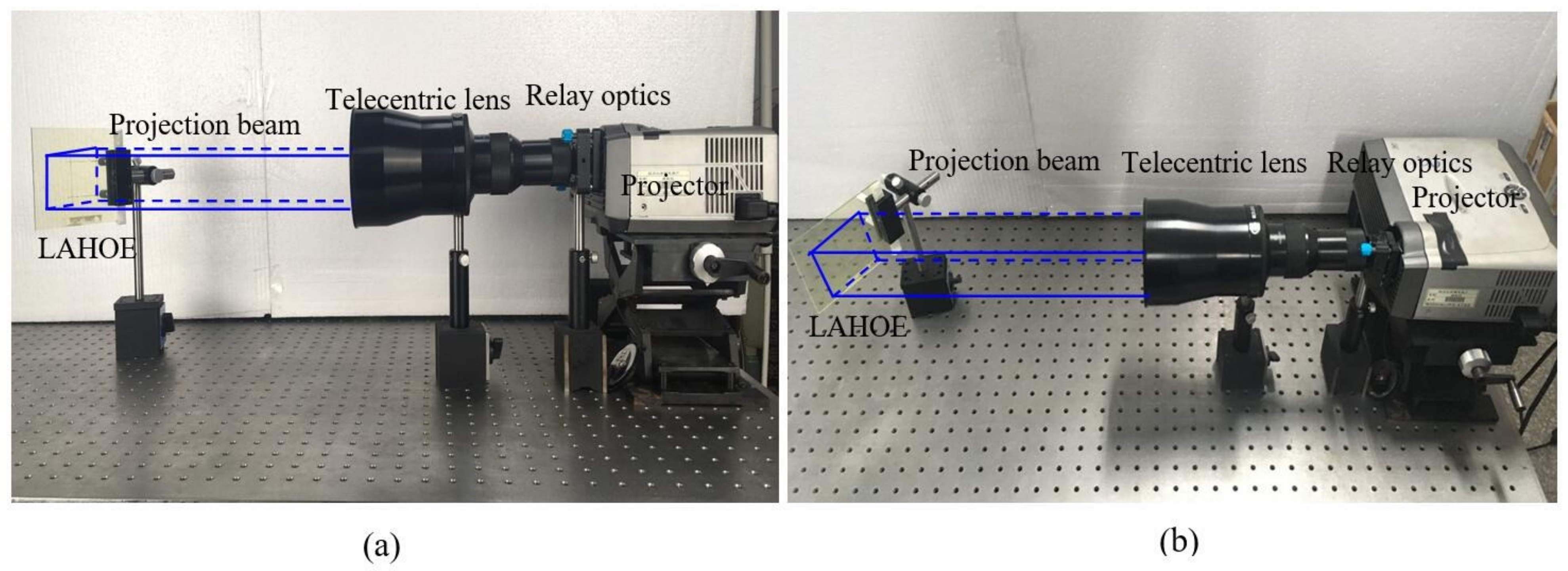
The acquired 3D data and the reconstructed 3D image of II are symmetrically related to each other. The LAHOEs of the above system are being used as a projection screen; the projection beam of the LAHOE is parallel light. So, the projection system consists of a spatial light modulator, a reverse projection lens, a relay optical element, and a telecentric lens. The telecentric lens and relay optics are used to collimate and expand the projection beam. Finally, the collimated light with EIA is projected on the LAHOE with an incident angle of
θ. The structure of the projection system is shown in
Figure 1. Because the projection system is not correct, the projection beam changes in the direction of the curvature of the projection lens, which is represented by the radial ratio distortion. It causes the image point to be shifted along the radial direction, and the larger the deformation is from the center point; this is the radial distortion of the projection system. In the assembly process of the projection system, the optical axis of the lens that comprises the projection system is not collinear. The present optical system is affected by eccentricity, leading to distortion of the image; this is the tangential distortion of the projection system. The distortion of the prism is mainly due to the manufacturing error of the projector CCD imaging matrix and the manufacturing error of the projection system objective. So, there is lens distortion in the projection system.
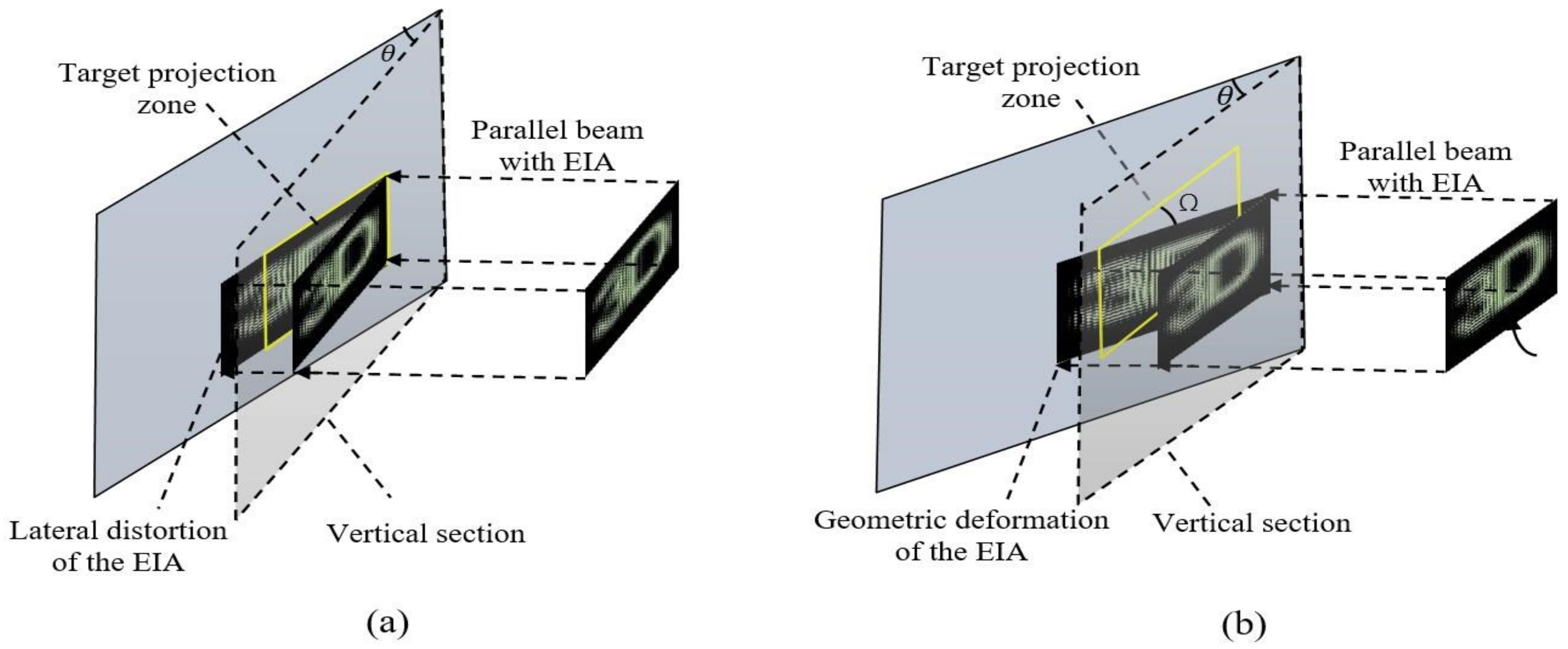
These LAHOEs of the above systems use the optical principle of off-axis imaging, which requires that the projection beam be projected at a certain angle
θ. As a result, the lateral distortion of the EIA occurs when the projection beam is projected onto the LAHOE, as shown in
Figure 2a. Because of the position shift of the projector, the EIA has geometric deformation, as shown in
Figure 2b. In the reconstruction process, an obliquely incident display beam leads to the different pixel densities in horizontal and vertical directions, which causes the difference in the angular resolution of 3D images in horizontal and the vertical directions. Because of elemental image array (EIA) distortions, it is difficult to accurately align the EIA with the LAHOE. Serious flip exists in the reconstructed 3D images, and it is difficult to build a large 3D display system. The distortion of the EIA affects the asymmetry of the 3D image reconstruction.
To solve the problem of the lateral distortion of the EIA, the Seoul National University has developed an on-axis LAHOE for a see-through integral imaging 3D display system [
19]; this system effectively solves the issue of the lateral distortion of the EIA but it does not solve the geometric of the EIA. Moreover, the diffraction beam and the reflected beam of the LAHOE cannot be separated. Therefore, the diffraction beams and the reflected beam of the LAHOE overlap each other, so the reconstructed 3D image is not clear, and it has serious crosstalk problems. The Tokyo Institute of Technology has developed a rapid calibration of a projection-type holographic light-field display system using hierarchically unconverted binary sinusoidal patterns [
20]. This method could rapidly calibrate the projection-type II 3D display system and solves the problem of the lateral distortion and the geometric deformation of the EIA.
To precisely align EIA and LAHOE, our group precorrected the lens distortion of the projection system, the distortion compensation method can be used to compensate for the lens distortion, and the EIA of before the project, based on the perspective transformation in computer graphics, can be used to resolve the lateral distortion and geometric deformation. In the process of 3D image reconstruction, the causes of asymmetry affecting 3D image reconstruction are analyzed and the issues that generate these asymmetric factors are addressed. As a result, the projected EIA has a uniform pixel density in the horizontal and vertical directions, and the precise alignment between EIA and LAHOE is realized.
2. System Configuration
To realize the precise couple between EIA and LAHOE, the projection beam in the reconstruction process makes the uniform pixel density in the horizontal and vertical directions. The distortion is caused by the projection lens. The lateral distortion and geometric deformation of the EIA are caused by the projection system. The causes of asymmetry affecting 3D image reconstruction are analyzed. Thus, an examination of the projection lens is performed first, and then lateral distortion and geometric deformation of the EIA in the projection system are analyzed.
2.1. Lens Distortion of the Projection System
The projection system consists of a spatial light modulator, a reverse projection lens, a relay optical element, and a telecentric lens. As shown in
Figure 1. The projection system is not corrected. Therefore, there has lens distortion in the projection system. The lens distortion of the projection system includes radial distortion, tangential distortion, and thin prism distortion. The lens distortion cannot be solved by the perspective transformation. Assuming the coordinates of the projective point without lens distortion are (
xp,
yq). The coordinates of the projection points with lens distortion are (
xu,
yv). The projection beam changes in the direction of the curvature of the projection lens, which is represented by the radial proportion distortion. It causes the image point to be shifted along the radial direction, and farther away from the center point. The mathematical model of the radial distortion can be expressed as:
δxr, δyr are the number of distortions in the horizontal and vertical direction caused by radial distortion and k1, k2 are the radial distortion coefficients.
In the assembly process of the projection system, the optical axis of the lens that consists of the projection system is not collinear. The actual optical system is affected by eccentricity, resulting in the distortion of the image. The mathematical model of tangential distortion can be expressed as:
δxd, δyd are the number of distortions in the horizontal and vertical direction caused by tangential distortion and p1, p2 are the tangential distortion coefficients.
The thin prism distortion is mainly caused by the CCD imaging array manufacturing error of the projector and the lens manufacturing error of the projection system. The mathematical model can be expressed as:
δxp,
δyp are the number of distortions in the horizontal and vertical direction caused by thin prism distortion and
s1,
s2 are the thin prism distortion coefficients. Therefore, without lens distortion imaging, the point coordinates are the sum of the with lens distortion imaging point coordinates and the number of the distortions of the imaging point, which can be expressed as:
k1,
k2,
p1,
p2,
s1,
s2 are the lens distortion coefficients and Equation (4) can be expressed as:
D is the coordinate matrix of the projective point without lens distortion and
E is the coordinate matrix of the projection points with lens distortion. The six coefficients of the lens distortion can be solved by three pairs of target values and actual values of the measured pixels. To obtain the lens distortion parameters, we selected the central position of the projection zone and obtain three pairs of the distortion values and the actual values of the closest point in the center of the projection zone. To improve the calculation precision, the distortion coefficient vector
P was obtained by the least square method. Then, the height mapping relation between the coordinate matrix of the projective point without lens distortion and the coordinate matrix of the projection points with lens distortion was obtained by Equation (5):
Thus, the projection zone without lens distortion was obtained.
2.2. The Lateral Distortion and Geometric Deformation of the EIA
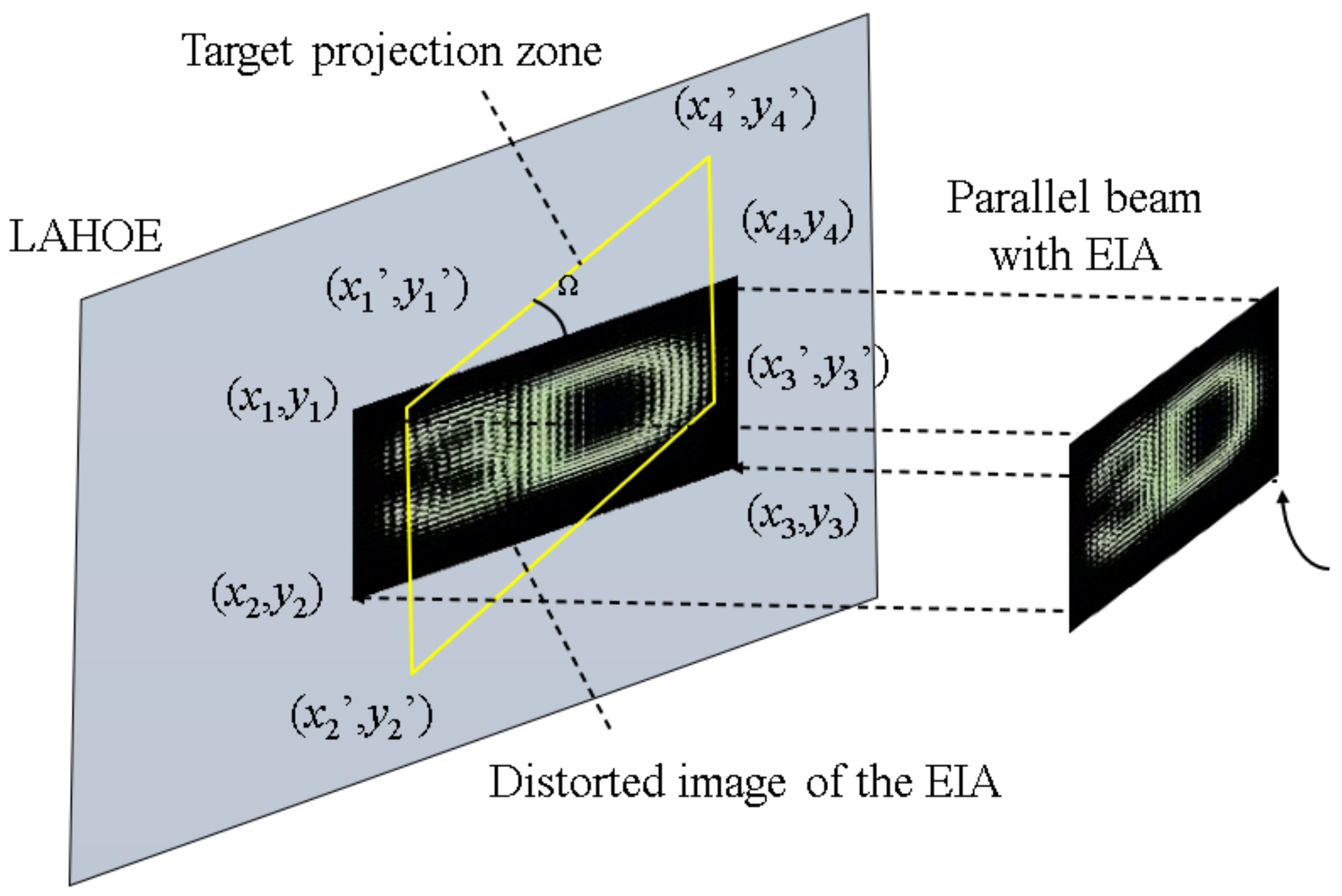
The lens distortion of the projection system has been solved. However, the lateral distortion and geometric deformation of the EIA remains to be resolved. As shown in
Figure 3, we must correct the distorted EIA image and project the non-deformed EIA into the target projection zone. The distortion of the EIA is corrected by the method of pre-correction the distortion of perspective transformation in computer graphics.
In computer graphics, perspective transformation is defined as a mapping from one plan to another. Perspective transformation can extract the translation and rotation matrix between two images from the homography matrix, and it is rendered based on the correct mapping relation, which satisfies the linear relationship. Assume that point Q (
xp,
yq,
z) is an image point projected onto the LAHOE without lens distortion by the projection system. P (
x,
y) is a target projection zone image point of the Q after the perspective transformation. The relationship between them can be expressed as:
A is the internal reference matrix of the projection system, which includes the image main point (u0, v0), the focal length fu in the x-direction, and the focal length fv in the y-direction of the image coordinates. R and t are the external reference matrix of the projection system. R consists of three rotation angles, α is the light axis pitching angle, β is the light yaw angle, and φ is the rotation angle of the light. The translation matrix t consists of tx, ty, and tz translation vectors in three directions. Therefore, the lateral distortion can be solved by the translation matrix t and the geometric deformation can be solved by the rotation matrix R.
The homography matrix between the real imaging zone and the target projection imaging zone can be expressed as:
Because it is a transformation in a two-dimensional plane, the coordinates of the
z-axis direction are removed. From Equation (10) the following two Equations can be obtained through:
In normalized processing, where
g = 1, eight variables need to be calculated. So, the matrix can be calculated by four pairs of matching points. Assume, (
x1,
y1), (
x2,
y2), (
x3,
y3), and (
x4,
y4) are four orientations in the original coordinate system of the distorted image of EIA without lens distortion, (
x1′,
y1′), (
x2′,
y2′), (
x3′,
y3′), and (
x4′,
y4′) are the corresponding point of target projection coordinate after projection transformation of the EIA. The relationship between them can be expressed as:
a, b, c, d, e, f, u, and v are the correction coefficients of the projection system. When the correction coefficients of the projection system are obtained, the distortion precorrection of the EIA can be determined, and the pixel mapping relationship between the mapping target projection zone and the original projection zone of the distorted image of EIA can be determined.
2.3. Correction of the Projection Zone
The correction process of the target projection zone is shown in
Figure 3. Before the correction, the checkerboard cannot overlap the target projection zone completely, because the checkerboard has lateral distortion, geometric deformation, and lens distortion, as shown in
Figure 3, and
Figure 4a shows that the projection system has lens distortion, lateral distortion, and geometric deformation. Equation (8) is used to correct the lens distortion. Then Equation (13) is used to correct the lateral distortion and geometric deformation. The corrected projection system has an extremely low distortion. The corrected checkerboard matches the target projection zone exactly, as shown in
Figure 4b.
3. Experiment and Results
The fabrication principle of the LAHOE is shown in
Figure 5. The fabrication of the LAHOE is the typical reflective holographic optical element. The interference pattern formed by an oblique plane wave reference beam and the spherical wave array, containing properties of the conventional lens array, is recorded into the holographic material in front of the lens array. In the experiment, a green solid-state laser with a power of 2000 mW was used as the light source, and the green-sensitive photopolymer material was used to fabricate the LAHOE. The thickness of the photopolymers is 15 µm; the refractive index of the polymer materials is 1.47, and the resolution of the polymer materials is 12,000 line/mm. The specific parameters of the optical devices are shown in
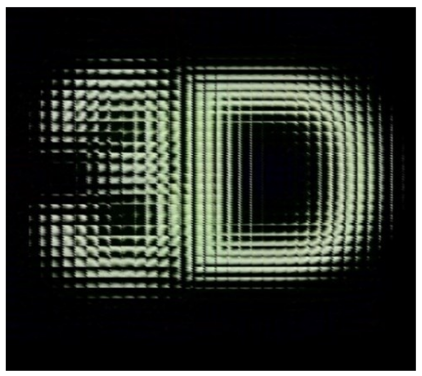
Table 1. An 80 mm × 90 mm large size LAHOE was fabricated, and the wavefronts of the lens array were reconstructed through white light, as shown in
Figure 6. The pitch of the lens elemental is 1 mm and the focal length is 3.3 mm. The diffraction efficiency of LAHOE is 84%.
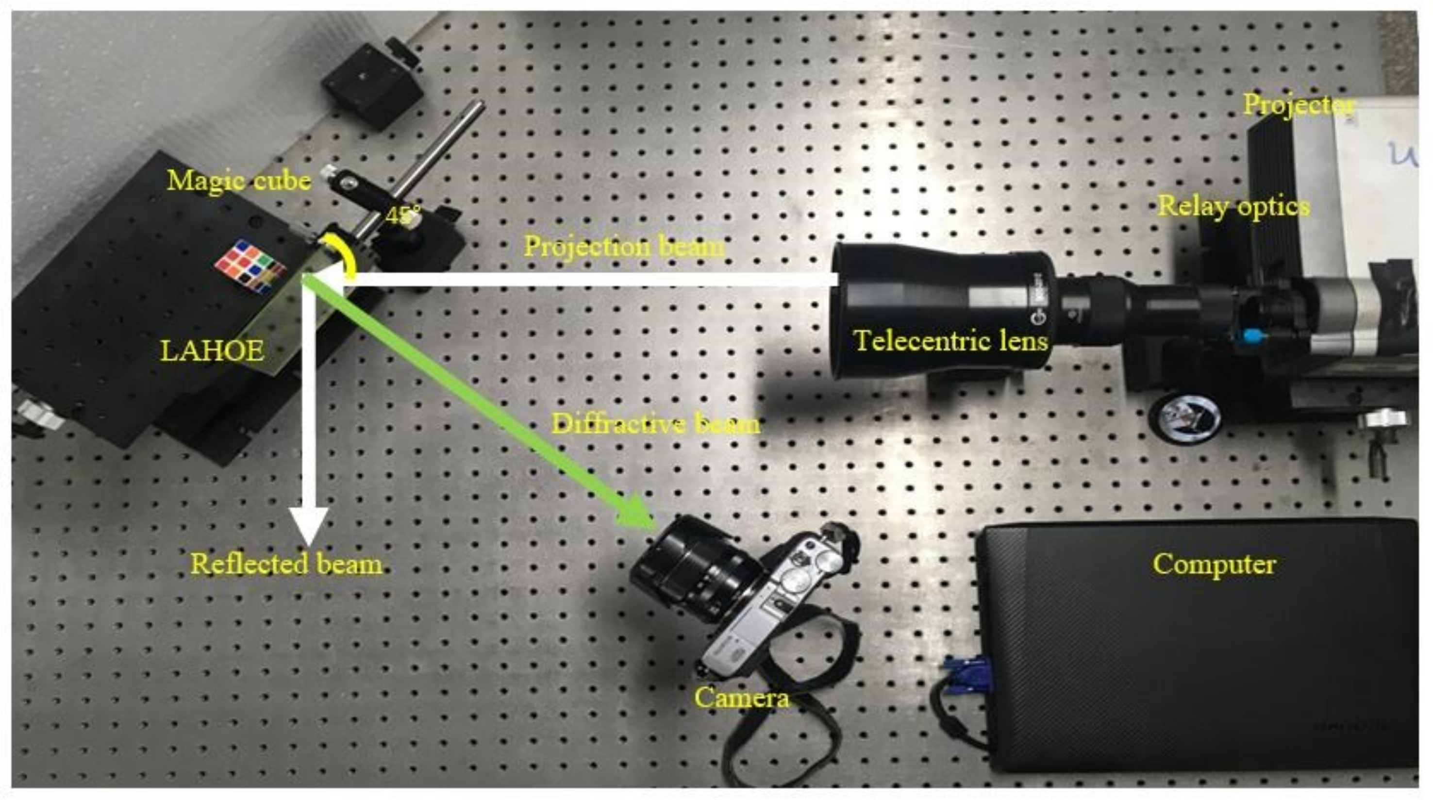
The experimental setup for the reconstruction of the 3D image is shown in
Figure 7. The magnification of the telecentric lens is limited, only a 50 mm × 38 mm rectangular parallel beam can be projected. Therefore, we chose the 35 mm × 35 mm region as the target projection zone on the large-size LAHOE. The telecentric lens and the relay optics serve to collimate the beam projected by the projector. The collimated projection beam with elemental image array was projected on the LAHOE with the incident angle of 45°. When the projection beam reaches the LAHOE, some of the beam produces diffracted light waves and reconstructs the 3D image, and one portion of the projection beam is reflected, and another portion of the projection beam crosses the LAHOE. The camera was used to obtain the 3D images of the diffracted beam reconstruction. The EIA was generated by the computer, as shown in
Figure 8. The EIA consists of 35 × 35 image elements, it contains “3” and “D”, in which the position of “3” is +6 mm and the “D” position is −6mm.
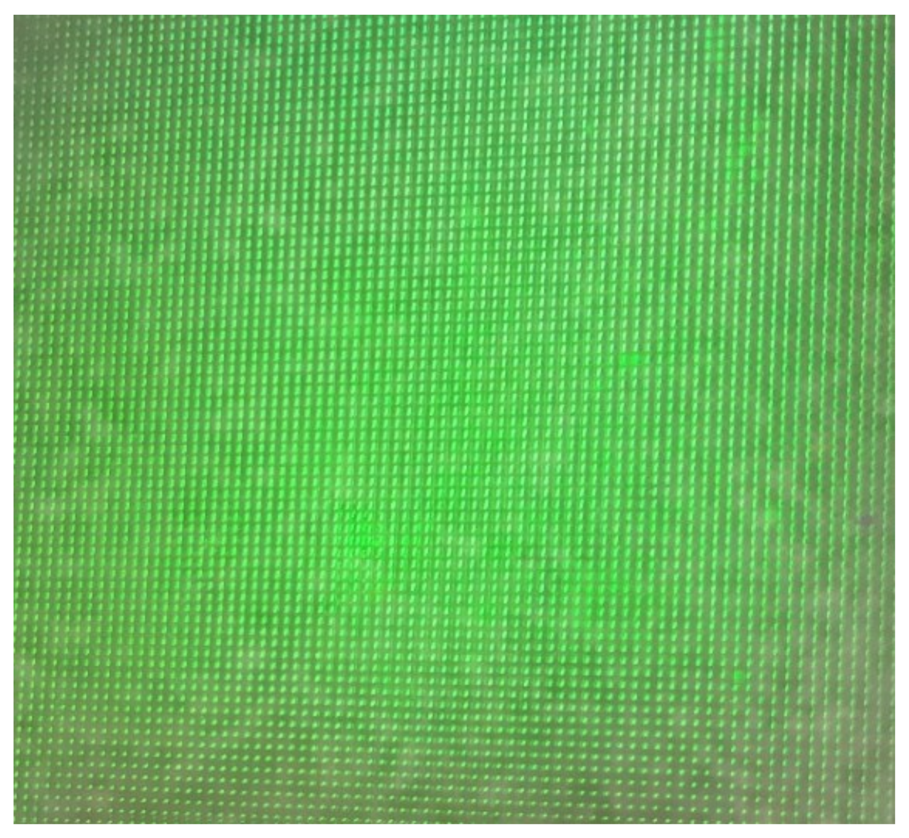
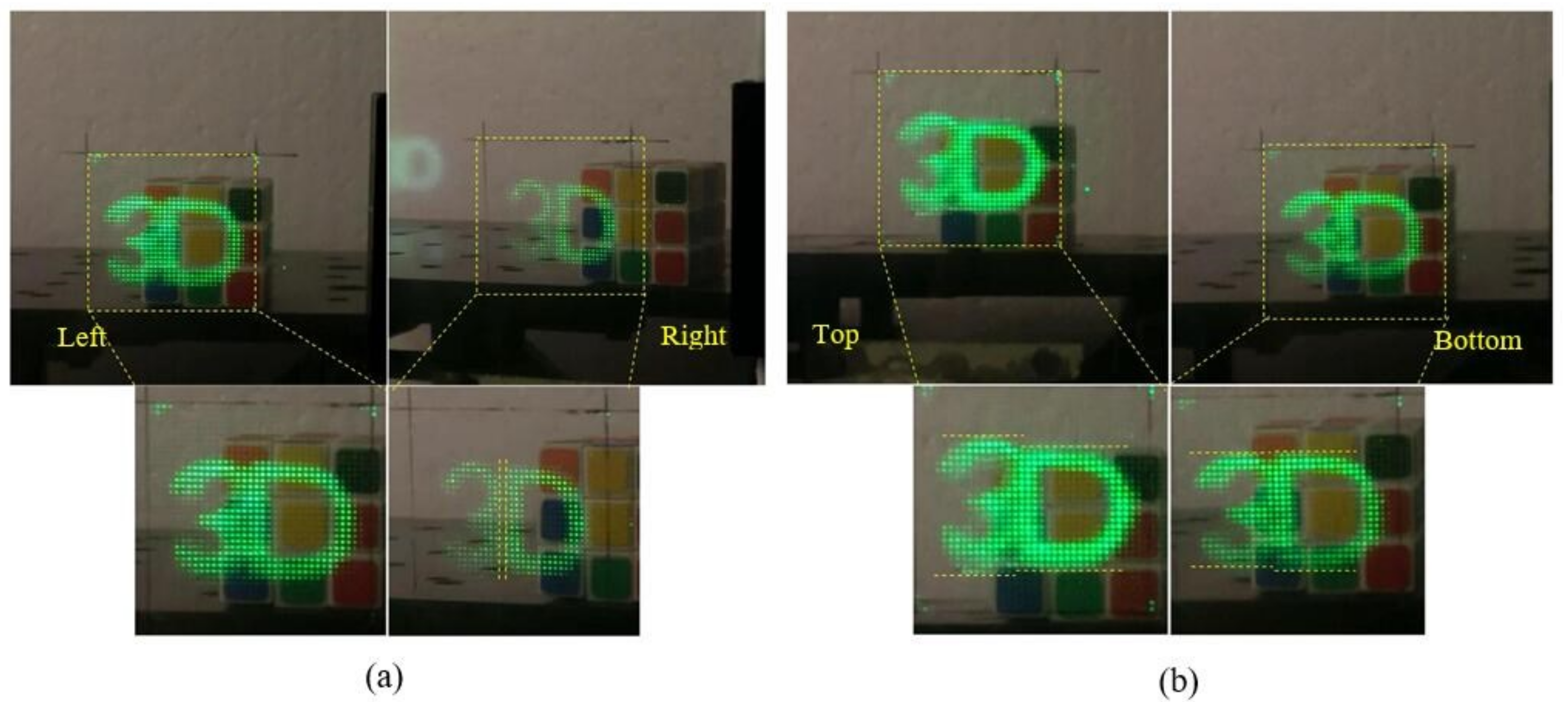
After correction of distortion of EIA, the EIA, and LAHOE realize precise coupling. In the process of 3D image reconstruction, the pixel density of the projection beam in the horizontal and vertical direction is uniform, as shown in
Figure 9a,b. In the reconstruction process, the projection beam was used to irradiate LAHOE. The LAHOE has the optical properties of a micro-lens array when Bragg conditions are satisfied. The EIA information carried in the reference light wave was modulated by the LAHOE to reconstruct the 3D image. We obtained four pictures from the left, right, top, and bottom four viewpoints. The distortion of EIA was eliminated. We can see the horizontal parallax of the virtual “3D” from the left and right images and the vertical parallax of the virtual “3D” from the top and bottom images. The reconstructed 3D images have obvious horizontal and vertical parallaxes. Visualization 1 clearly shows the horizontal and vertical parallaxes between the “3”, “D”, and the real-world scene. Reconstructed 3D images exhibit uniform pixel density in horizontal and vertical directions.
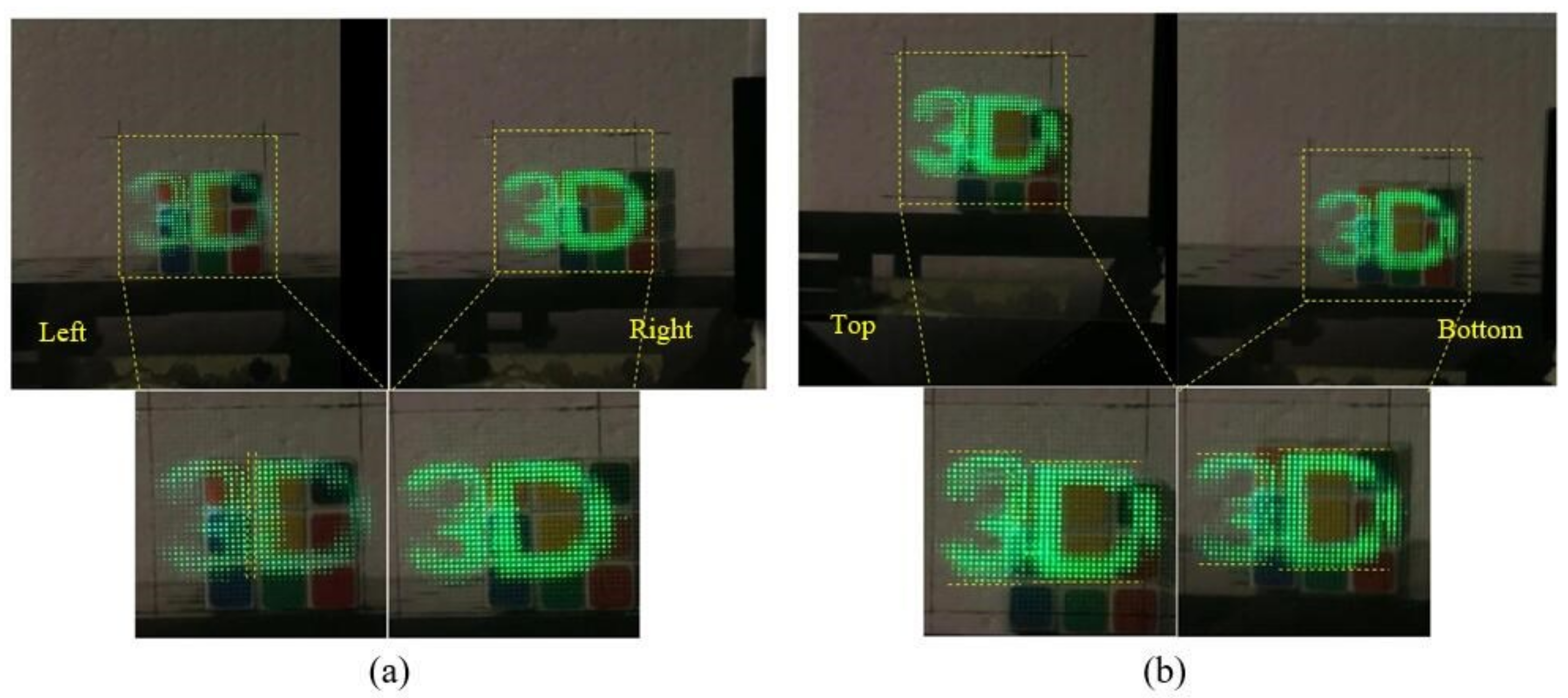
The 3D images reconstructed by the EIA without any correction are shown in
Figure 10. The EIA exhibits lateral distortion, geometric deformation, and lens distortion, such that the EIA cannot be accurately coupled to the LAHOE. Consequently, it has different densities of pixel in horizontal and vertical directions, which causes the difference in the angular resolution of 3D images in horizontal and vertical directions. Reconstructed 3D images have serious crosstalk, weak definition, and poor image quality, and the stereoscopic sense of reconstructed 3D image is not evident. We obtained four pictures from the left, right, top, and bottom four viewpoints. We can see the horizontal parallax of the virtual “3D” from the left and right images, and the vertical parallax of the virtual “3D” from the top and bottom images, but the 3D images have serious crosstalk and weak stereoscopics. The pixel densities are different in the horizontal and the vertical directions, and the resolution of the reconstructed 3D images is different in the horizontal and vertical directions. Visualization 2 shows the horizontal and vertical parallaxes between the “3”, “D”, and the real-world scene, but the 3D images have serious crosstalk.


