1. Introduction
With the development of big data and edge computing, smart grids [
1,
2] have been promoted. The core of the smart grid provides a cyber-physical system (CPS) [
3], which transmits the information collected by the sensing device in the power system to the controller. An increasing number of intelligent algorithms [
4,
5,
6,
7] have been introduced into this field. It applies the result of instruction analysis to the power field equipment to ensure the stability of the power field equipment. To realize the reliability of the CPS, we should design a real-time communication network to provide a guarantee for it. A time-sensitive network (TSN) is based on the conventional Ethernet. It combines clock synchronization and resource reservation to simultaneously transmit high reliability (HR) flow, medium reliability (MR) flow, and low reliability (LR) in the network; thus, it provides deterministic data interaction and delay for embedded instrument devices in the network [
8]. However, a wide range of sensor networks may need to be connected to each other. TSN has good compatibility and scalability, and it is decentralized and symmetric because of the uplink and downlink as well as architectural designs. It can be used as a backhaul network or backbone network of multiple sensor networks or directly connect sensors, controllers, and actuators. For the data acquired from various sensors, different real-time requirements should be individually met. The TSN network architecture has significant natural advantages in meeting several real-time requirements of sensors, and it has wide adaptability and easy deployment. Artificial intelligence algorithms, such as Convolutional Neural Networks (CNN) and genetic algorithms, are often involved in network scheduling [
9,
10,
11,
12,
13].
In the substation communication process based on IEC61850 [
6,
14], the data flow is divided into three types: express flow, moderato flow, and slow flow. The response delay corresponding to the three types of messages is 10–500 ms. To further improve the certainty of communication between stations, we introduced a TSN to reduce the aforementioned delay to a microsecond level. The three data flows correspond to HR flow, MR flow, and LR flow in our study.
To ensure the deterministic delay and jitter of HR flow, we should consider MR flow and LR flow in the routing and scheduling process to improve scheduling performance considerably. The joint routing and scheduling problem calculates the offline gate control list (GCL) of all flows [
15] using an algorithm before deploying the network. When the network is running, the switch schedules the data flow through the scheduling list to realize the deterministic data flow transmission. Additionally, the GCL can be online, which could cause a certain degree of complex calculations and destroy the existing scheduling strategy, thereby generating a new GCL to satisfy the needs of new scheduling tasks.
The structure of the paper is as follows:
Section 2 introduces related works on TSN routing and scheduling, which was the main topic of this study.
Section 3 briefly describes the relevant standards of TSN and the substation communication configuration scheme based on TSN.
Section 4 presents the proposed system model designs and constraints of the flow.
Section 5 elaborates on the routing and scheduling processes of the algorithm, including preprocessing, scheduling calculation, and online monitoring.
Section 6 comprehensively considers the influence of the flow, quantity, and scale of network topology on the algorithms’ performance and compares it with other algorithms [
16,
17,
18].
Section 7 summarizes the study.
2. Related Work
TSN routing and scheduling research can be divided into two types: offline and online scheduling [
19]. Most researchers design offline schedules because the process is static, and all data flow, topology, scheduling constraints, and other data are known. In contrast, the online scheduling process is dynamic and variable, wherein dynamic adjustments are made according to changes in the data flow, network topology, and scheduling tasks. However, this process is often complicated.
Regardless of offline or online scheduling, the core task of the TSN scheduling algorithm is to calculate the GCL available for data scheduling. The solution method of the scheduling list is solved using approaches such as satisfiability modulo theories (SMT) [
20], ILP [
21], network calculus [
18], or swarm intelligence optimization [
17,
22,
23,
24]. The authors of [
17] proposes an improved ant colony algorithm, which aims to optimize the queuing delay in the data flow scheduling process and evaluates the average transmission delay and jitter of data flow scheduling by adding port and data flow constraints; the experimental results have achieved good performance indicators. The authors of [
20] proposes an offline scheduling algorithm based on SMT. By adding data flow constraints, the maximum deadline of data flow transmission is used as a measurement index, and the schedulability of BE (best effort) flow is taken into account. In addition, the algorithm is also performing TSN simulation based on the INET framework of OMNET++, and the simulation results meet the performance indicators related to scheduling. The authors of [
22] proposes an improved genetic algorithm, which considers both the routing and scheduling of data flows, effectively improves the scheduling performance of TT flows, and rationally optimizes network resource allocation. The authors of [
24] proposes a hybrid genetic algorithm, which fully considers scheduling constraints, network topology scale, and data flow scale, effectively improving timeslot utilization and ensuring the real-time nature of data flow transmission. The scheduling constraint of the data flow in the solution process may be a single HR flow or the joint scheduling of HR and MR flow [
16]. Finally, hardware or software verifies the algorithm according to a specific scenario, wherein the software verification uses a simulation program [
25] or OMNET++ simulation software (omnetpp-5.5.1) [
26] that simulates the hardware environment.
The main contributions of this study are as follows:
- (1)
This study designed an offline and online TSN hybrid data flow routing and scheduling algorithm. Compared with previous studies [
19], the offline and online scheduling algorithms designed in this study consider changes in the network topology and data flow. Previous studies [
19] considered the change in network topology in the online scheduling mode and combined it with the offline mode to reconstruct a new network topology. The algorithm can prevent the failure of scheduling calculations caused by new equipment access;
- (2)
This study presents an integration method of TSN and IEC61850. Simultaneously, three types of messages in the substation: express flow, moderato flow, and slow flow, are mapped to HR flow, MR flow, and LR flow in the TSN network. The introduction of time-sensitive technology can effectively reduce the response time during flow transmission, from milliseconds to microseconds. In the context of energy interconnection, the introduction of a reliable TSN communication technology can improve the certainty of communication between substations;
- (3)
Finally, this study discusses the forwarding and dispatching problems of three different data flows, which is more in line with the real-time scenario of hybrid data flow transmission and is of great significance to research. Compared with previous studies [
16,
17,
19], this study not only considers HR flow and MR flow but also considers the schedulability of LR flow. This is necessary for flow transmission between the substations.
4. System Model
In
Section 4.1, we establish a system, scheduling task, and traffic models. In
Section 4.2, we add transmission constraints to the traffic model. The model and constraints established in
Section 4 are applied to the routing and scheduling algorithm described in
Section 5. For specific design methods, please refer to
Section 5.1,
Section 5.2,
Section 5.3,
Section 5.4,
Section 5.5,
Section 5.6.
4.1. System Model
For the convenience of representation, we used the tuple,
, to represent the network topology [
15]. Herein
is a set of nodes in the topology graph, including substation node
and switching node
;
denotes a set of full-duplex links. In this study, the transmission rate of the full-duplex physical link was 1 Gbps.
represents the application [
32],
represents the scheduling task running on the node, and
represents the virtual link connection established between tasks.
A real-time scheduling task is initiated by the substation node and arrives at the next substation node within the deadline. In practice, we try to allow more data flow to be scheduled within the deadline to improve the overall scheduling performance.
In the process of flow routing and scheduling, we considered three types of flow, including HR flow, MR flow, and LR flow. Under normal circumstances, HR flow has the highest QoS priority, and the unschedulability of data flow occurs primarily in the MR and LR flow. We used set S to represent the three types of traffic: , where represents the HR flow set, represents the MR flow set, and represents the BE flow set. The dictionary stores the corresponding attributes of the data flow, , where represents the frame length, represents the offset of the frame, represents the sending period, and represents the sending deadline.
The integration of network topology and application programs determined a reasonable routing and scheduling way for a flow. Routing determined the path of data flow routing between nodes. Scheduling determined whether the data flow could be scheduled based on the routing path and combined with parameters, such as the size of the data flow, transmission period, and deadline. These parameters were defined when designing the model of the flow attribute . When the flow could not be scheduled, timeslot optimization was used to determine whether the data flow could arrive within the deadline.
4.2. Related Constraints
Here, we add transmission constraints based on the three types of flows. The application ensures that each node should reasonably allocate the timeslot of the task within a hyper period, define the relevant constraints and forwarding requirements, determine the switching node and the substation node, and send the data flow to the destination simultaneously.
Related constraints are as follows:
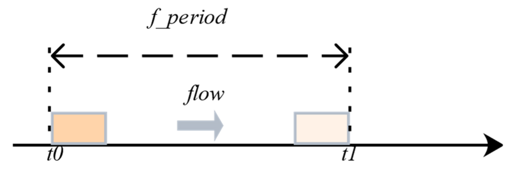
Constraint1: As shown in
Figure 4 and Equation (1), because the transmission of the flow is periodic, transmission should be completed within this period. In addition,
to
represent a transmission period; the timeslot occupied by the data flow should be within this period to ensure that it does not overflow. Herein,
represents one transmission period and
represents the specific timeslot allocated by the data flow in the period
Constraint2: As shown in
Figure 5 and Equation (2), the transmission offset of the data flow should be between the minimum offset and the maximum period. This is considering that the periodically transmitted data flow will deviate from the fixed transmission timeslot owing to jitter. We must ensure that when an offset occurs, the data flow does not overflow the cycle owing to the offset. This may cause packet loss or unschedulability, which is very serious for the system. In addition,
to
represent the offset of the data flow and
to
represent the timeslot of the data flow. After determining the offset of the data flow, we should ensure that the data flow will not overflow its period. Here,
represent data flow offset.
Constraint3: As shown in
Figure 6, the transmission interval of the frame must be equal to the period. In addition, the data flow with
as the transmission starting point should ensure that the transmission starting point of the data flow is
. Additionally, the transmission interval must be one period. Essentially, the data flow at
should not be transmitted prior to
. The periodicity of the data flow transmission must be guaranteed.
Constraint4: The link is exclusive to the frame during transmission, and only one flow is allowed on the link. Essentially, other data flow cannot be transmitted in a certain occupied timeslot;
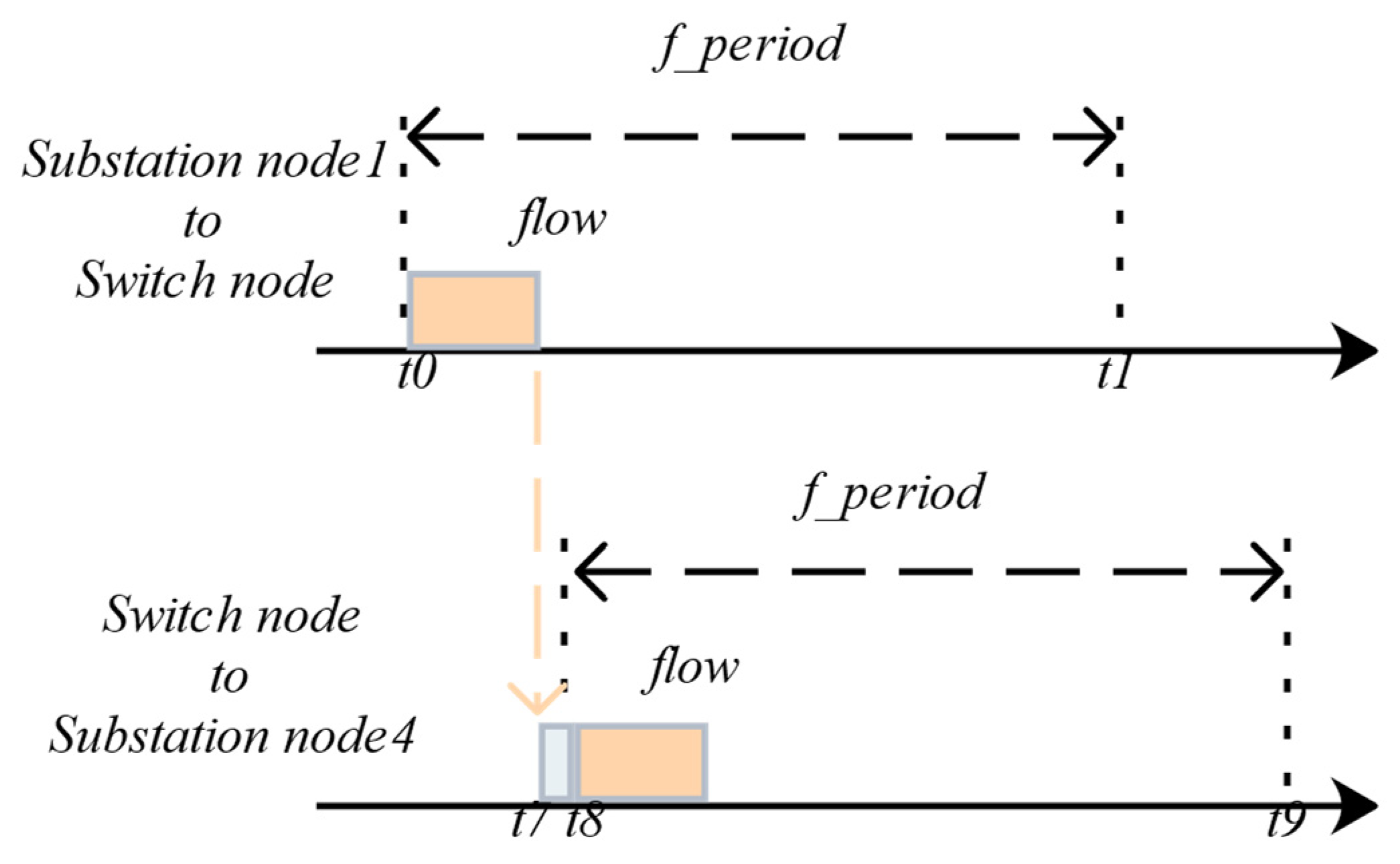
Constraint5: As shown in
Figure 7 and Equation (3), when the data flow passes through the switch, the transmission of the next data flow should be greater than the delay of the switch in the previous data flow. In addition, the delay caused by the data flow passing through the switch is from
to
; therefore, we should wait for a processing delay before sending the next data flow. Essentially, the switch node in the figure will have a delay from receiving the data flow to transmitting the data flow. This issue must be considered during the simulation.
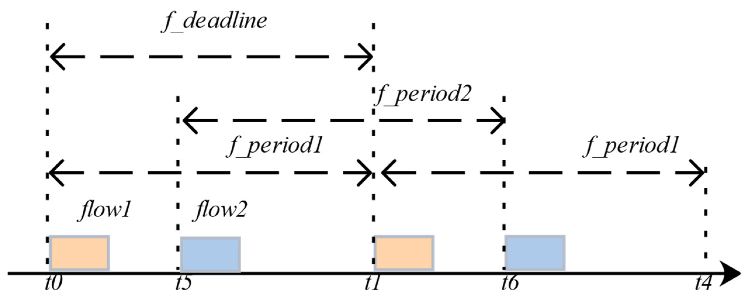
Constraint6: As shown in
Figure 8, the delay in the entire transmission process of the flow transmitted between nodes should be less than the entire scheduling period of the application. Essentially, the hyper-period from
to
is composed of the period of data flow1 formed by
to
and the period of the flow2 formed by
to
. Both flow1 and flow2 should not exceed the overall scheduling period of the data flow. Thus, all the data flow can be scheduled;
Constraint7: As shown in Equation (4), the
generated during the entire transmission process of the flow transmitted between nodes should be less than
; herein,
represents the total scheduling time (corresponding to
in the figure), and
represents the deadline (corresponding to
in the figure):
As shown in Equation (5), if there is no data flow queued in the transmission queue, the maximum offset of the data flow transmission is less than the
.
As shown in Equation (6), if there are multiple data flows in the queue, the scheduling time of the flow is the task scheduling period, and the scheduling time of the next flow should be less than
; herein,
represents the maximum offset,
represents the data flow period, and
represents the queuing delay.
5. Routing and Scheduling Framework
The purpose of the algorithm is to generate a GCL that satisfies the constraints in [
33,
34]. Here, we propose a novel routing and scheduling approach architecture based on SMT [
35] to generate an effective scheduling list. The framework included six parts: mapping, stream processing, timeslot occupancy, task scheduling, communication scheduling, and dynamic monitoring. As shown in
Figure 9, we used a process chart to describe offline and online routing and scheduling algorithms (
Section 5.1,
Section 5.2,
Section 5.3,
Section 5.4,
Section 5.5,
Section 5.6).
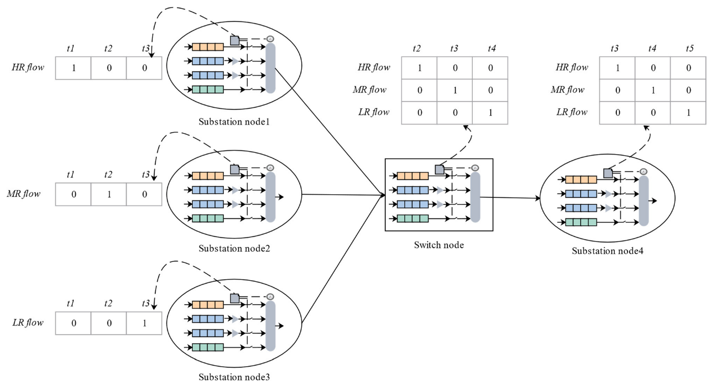
As an example,
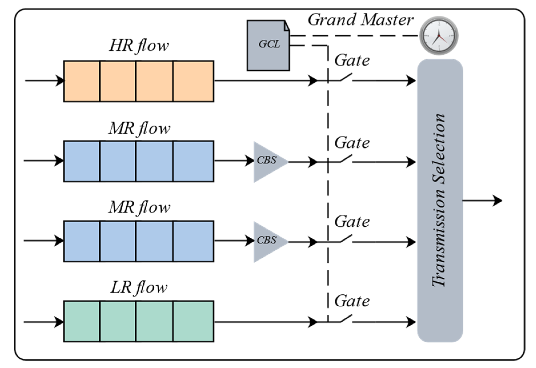
Figure 10 briefly describes the computing tasks of the routing and scheduling frameworks. We assumed that the preprocessing work had been completed, including mapping, stream processing, and timeslot occupancy. The scheduling GCL was obtained through task and communication scheduling. The TAS running on each terminal node (substation node1–4) contained eight queues. However, we described only three queues in the figure to simplify the process. The substation nodes sent three data flows—HR, MR, and LR. Each substation node periodically sent data flow according to an offline dispatch GCL. One switching node received the mixed transmission data flow, combined the hyper period and scheduling constraints to schedule the task, scheduled the hybrid transmission data flow according to the calculated GCL, and transmitted it to substation node4.
5.1. Mapping
To enable the substation nodes in the network topology to perform scheduled calculation tasks, it was necessary to map the application program to the network topology. In the initial input file, the network topology and applications were separated. The network topology was written in XML, including all nodes (substation and switching nodes) and the connection status of the nodes; however, the nodes were not divided. This implies that we had to obtain the corresponding substation nodes and switch nodes through corresponding processing. By traversing the number of adjacent node connections of the node, we could obtain the substation and switching nodes, establish a link to them, and obtain the network topology with the node identification. Subsequently, the application contained scheduled calculation tasks that had to be executed on the substation node, and we could obtain the attributes of different types of data flow. The input application program was traversed, virtual links were established among the tasks of different substation nodes, and the tasks were initialized as well as stored in the corresponding substation nodes.
5.2. Stream Processing
After mapping, we obtained a scheduling task that contained the attributes of the data flow. Thereafter, we processed the data flow of the scheduled computing task executed on the substation node. First, it was crucial to obtain the hyper period of the flow set. The hyper period was used to evaluate the feasibility index for a group of data flow to satisfy the schedules. As the name implies, if there are several flow tasks, L.C.M. of these tasks is named by hyper period. When a group of periodic flow can be scheduled in a hyper period, they repeat every other hyper period and run uninterrupted.
5.3. Timeslot Occupancy
We simulated the scheduling of eight periodic data flows to design an offline GCL. The timeslot occupancy was obtained by calculating the worst time occupied by the arrival time in the worst case of different data flow. Note that to increase the occupancy rate of the hyper period timeslot, we must compress the deadline of each data flow considerably to achieve compression of the overall data flow scheduling period. Finally, we used the SMT solver to add constraints to obtain the maximum timeslot occupancy value.
HR flow is the most stable, with an almost constant scheduling period and execution time. Therefore, the compression deadline discussed above refers to LR and MR flows because they are the key factors for evaluating scheduling performance.
5.4. Task Scheduling
Task scheduling determines the GCL on the substation node and reasonably arranges the timeslots occupied by different tasks. The hyper period of all data flow to be scheduled was obtained in the stream processing part. During task scheduling calculation, first, the data flow was divided. For non-HR flow, the offset and cutoff times were calculated again. This result was obtained in the timeslot occupancy part. Second, we traversed the task to calculate whether the data flow satisfied the bandwidth occupation. For a data flow that exceeded bandwidth occupation, reasonable timeslots were reallocated. Finally, we obtained the task scheduling strategy that satisfied the terminal node and timeslot allocation of each data flow.
5.5. Communication Scheduling
A communication schedule establishes communication and data stream transmissions between different nodes. First, we determined whether the offset and deadline between nodes and the period of the data flow satisfied the requirements. Second, the fusion of the mapping section to the topology map, application program, and substation node scheduling GCL was obtained from the task scheduling section as input. Third, the stream constraint conditions between nodes were established to determine whether the communication schedule was satisfied. Finally, the final scheduling link sequence was obtained through a communication scheduling calculation, and the communication schedule was completed.
5.6. Dynamic Monitoring
Dynamic monitoring provides flexibility and diversity in scheduling. We could monitor the connected switching nodes and substation nodes at any time and change the scale of the initial topology to achieve online scheduling.
In the topology initialization process, we input the newly accessed node information into the configuration file to update the network topology. The scheduler re-executed procedures 5.1 to 5.5 to calculate the schedule list that satisfied the constraints and used it as the new schedule criterion.
6. Experimental Result
To verify the superiority of the scheduling algorithm, Python was used to write the offline and online scheduling algorithms. The algorithm included network topology, task scheduling, and related constraints, and it was tested on a PC with a hardware specification of Intel Core i7-8750 H and 16 GB RAM. Moreover, Python supports SMT, ILP, and network calculus in the programming process. Although the abovementioned methods are effective for TSN data flow routing and scheduling calculations, SMT provides better support for Python, and the library functions are clear and simple, which is convenient for us to develop. Therefore, in the solution process, we used an SMT-based Z3 solver to complete the TSN data flow for routing and scheduling calculation tasks. Compared with ILP and network calculus, the execution process of the Z3 solver based on SMT is simple and clear and has a relatively short algorithm execution time.
We used the network topology shown in
Figure 11, which includes four substation nodes (Substation node1, Substation node2, Substation node3, and Substation node4) and a switch node. As summarized in
Table 1, the scheduling task includes eight data flows, which are four HR flows (S1–S4), three MR flows (S5–S7), and one LR flow (S8). The MR flow was all Class A, and the default idle slope was 75%. Herein, R represents the sending path of the flow, T represents the period of the flows, D represents the deadline of the flows, and P represents the length of the flows. The transmission times of HR flow, MR flow, and LR flow were 6, 12, and 12 µs, respectively.
The core task of routing and scheduling calculated the GCL, which is cyclic and can realize scheduling tasks for all data flow in a hyper-period. All data flows to be scheduled were sent to the link by the same port of the node.
We scheduled the data flow according to their priority and generated the GCL. In this case [
16,
17,
22], we ran the algorithm 30 times and noted the average time. The overall TSN switch scheduling periods were 206.3, 209.4, and 211.3 µs, which caused the MR flow not to be scheduled, thereby resulting in scheduling failure. On the contrary, we ran our algorithm 30 times in the same case, and our result in an average scheduling period was 198.4 µs for the hybrid data flow, which satisfied the worst-case deadline, and all data flow could be scheduled.
For the purpose of verifying the general applicability of the scheduling approach, we changed the count of flow and the scale of the network topology, and we applied the algorithm to verify its scheduling performance. The scheduling results when the network topologies were 10, 20, 40, and 100, and when there were eight data flows are presented in
Table 2 (Y means that data flow can be scheduled).
It can be observed from
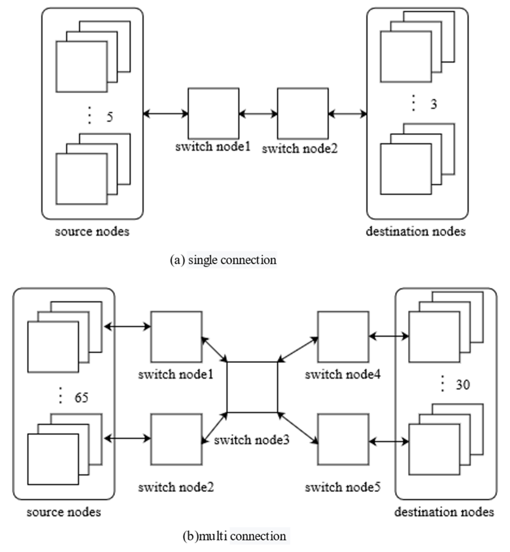
Table 2 that our algorithm can maintain the schedulability of the data flow in dynamically changing topologies, which improves the reliability of the algorithm. In addition, in the 10-node network topology, there were five source nodes, three destination nodes, and two switch nodes. The 20-node network topology contained 10 source nodes, five destination nodes, and five TSN switch nodes. In the 40-node network topology, there were 25 source nodes, 10 destination nodes, and five TSN switch nodes. The 100-node network topology contained 65 source nodes, 30 destination nodes, and five TSN switch nodes.
The network topology models of scales 10 and 100 are shown in
Figure 12a,b, respectively. The network topology models of scales 20 and 40 were identical in the structure of the switch node. In four cases, switch node1 connected to the source node was selected as the test node, and the algorithm was run 30 times on average. The average scheduling period was 194.3 µs.
In addition, as summarized in
Table 3, when the number of flows is 8, 10, 20, and 40, and the network topology scale is 10, we verified the impact of the number of flows on the performance of the algorithm scheduling (Y means that data flow can be scheduled).
As summarized in
Table 3, we selected four different flow models, among which the data flow with a scale of 10 contained six HR flows, three MR flows, and one LR flow. The flow with a scale of 20 contained 12 HR flows, six MR flows, and two LR flows. The flow of size 40 contained 23 HR flows, 12 MR flows, and five LR flows. We ran the algorithm 30 times on average, and all data flows were scheduled.
In addition, we compared the algorithm execution times with those reported in the literature [
16,
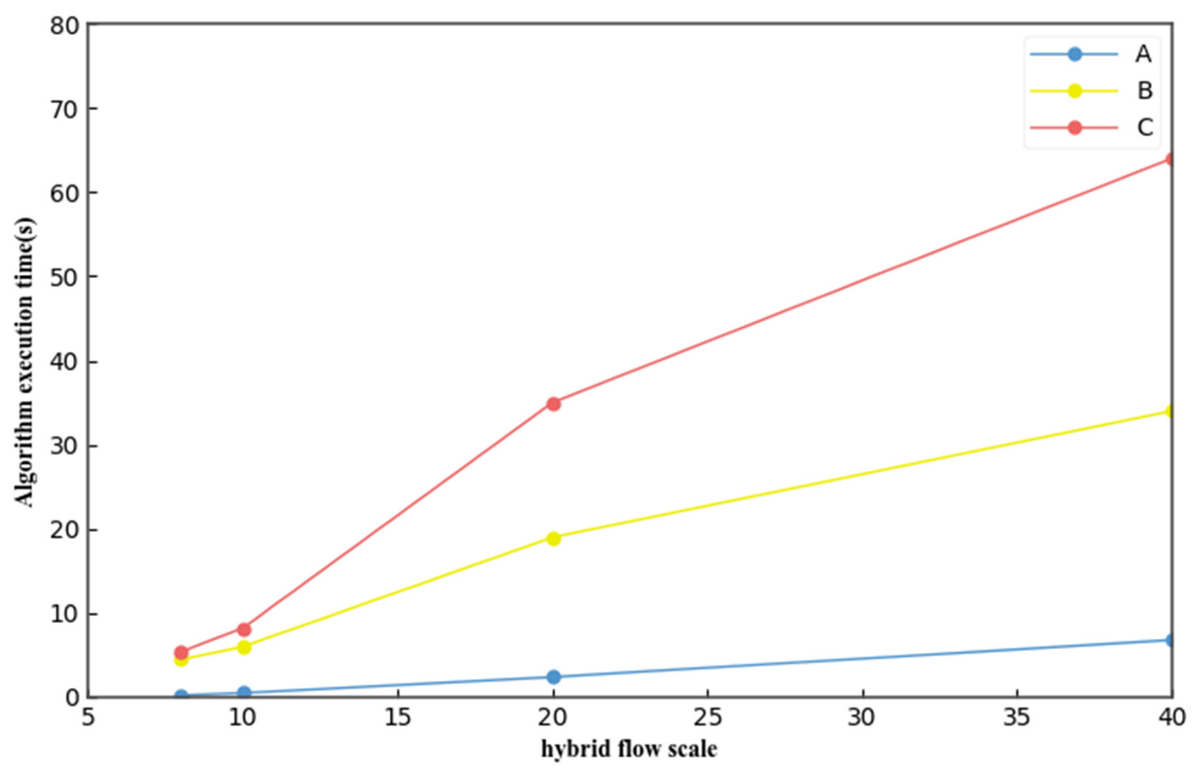
17]. The execution time of the algorithm when the scale of network topology remained unchanged at 10, and the scales of data flow were 8, 10, 20, and 40 is shown in
Figure 13. In a small-scale data flow, there was little difference in the execution times of the three algorithms. However, with an increase in the data flow scale, our algorithm (A) exhibited a better algorithm execution time than those in [
16] (B) and [
17] (C).
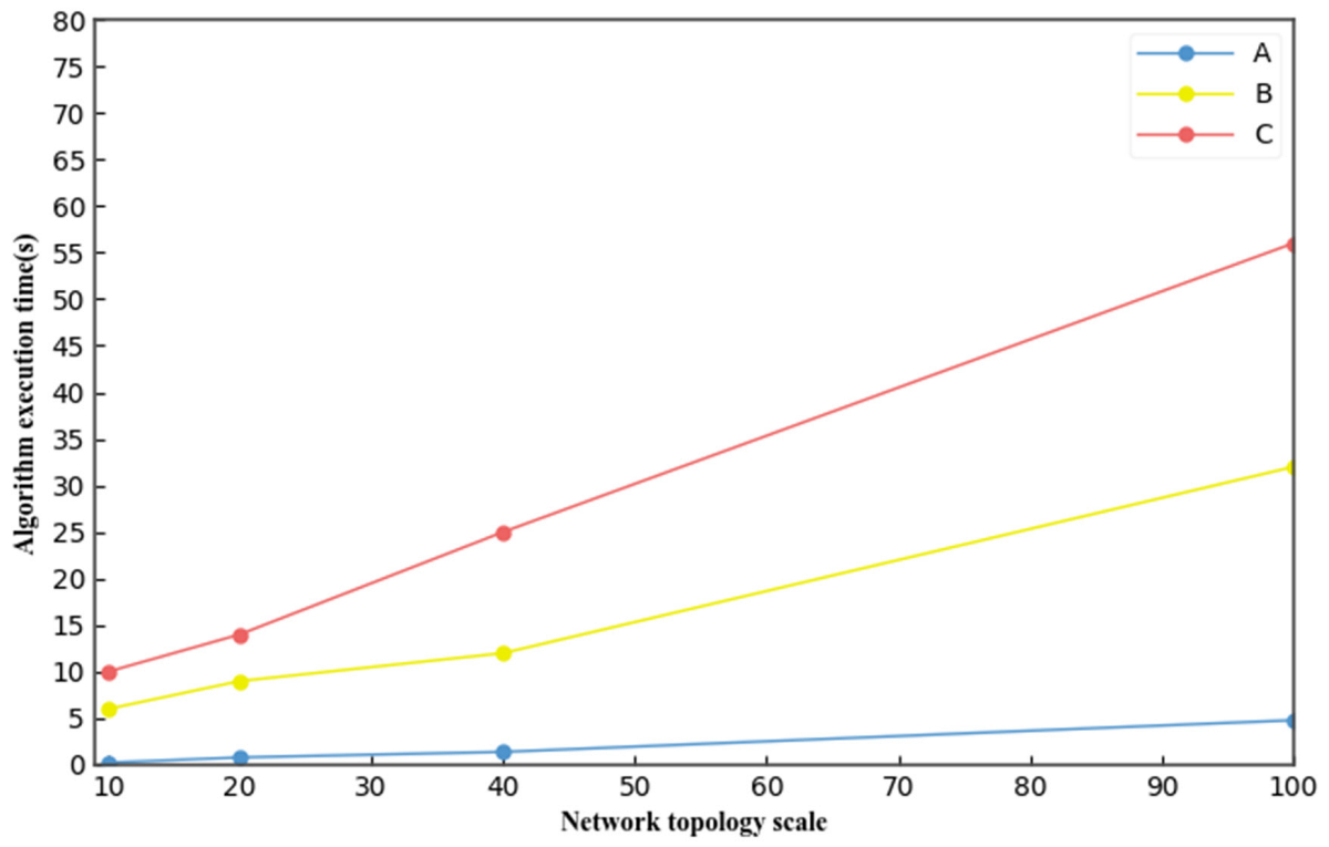
Similarly, the execution time of the algorithm when the data flow scale remains unchanged at eight and the data flow scales were 10, 20, 40, and 100 is shown in
Figure 14. In small-scale networks, there is little difference in the execution time of the three algorithms, but with an increase in the network topology scale, our algorithm (A) exhibited a better algorithm execution time compared with those in [
16] (B) and [
17] (C).

