Article

Characteristic Analysis of the Outer Sheath Circulating Current in a Single-Core AC Submarine Cable System

School of Water Resources and Hydroelectric Engineering, Xi’an University of Technology, Xi’an 710048, China
*
Author to whom correspondence should be addressed.
Symmetry 2022, 14(6), 1088; https://doi.org/10.3390/sym14061088
Submission received: 14 April 2022 / Revised: 19 May 2022 / Accepted: 23 May 2022 / Published: 25 May 2022
(This article belongs to the Section Computer)

Abstract

:
The single-core alternating current (AC) submarine cable can be provided with an outer sheath that is firmly grounded on both ends of the cable. The circulating currents of the outer sheath are generated to be almost as large as the conductor current. The outer sheaths, which have different structures and properties, generate unwanted losses, asymmetric distribution of circulating current, and extra heat in the single-core AC submarine cables. The formation mechanism of the circulating currents in the submarine cable sheath and armoring is analyzed from the perspective of electromagnetic shielding using electromagnetic transient theoretical analysis, simulation calculation, and field experiments. Equations for calculating the circulating currents of the sheath and armoring are proposed, and influences of these relationships that include the different material characteristics of the sheath and armoring are analyzed. The influence factors, which include different levels of magnetic armoring permeability, resistivity, and ground resistance of the outer sheath, can affect the symmetrical distribution of the circulating current in the outer sheaths. We propose using the phase differences to determine the material properties of each metallic section in the submarine cable.

1. Introduction

As a means of power transmission, cables have an important application value in the urban power supply, offshore wind power transmission, and high-speed railway power supply. With the rapid development of the marine economy and offshore wind power generation, submarine cables have been widely adopted in marine power transmission systems [1]. Single-core submarine cables are used as an option for power transmission between islands and the mainland, and the ability of submarine cables to transfer bulk power over long distances can satisfy the future needs of ever-expanding marine power transmission systems [2].
Many papers have analyzed the structure of the single-core AC submarine cable and the circulating current mechanism of its outer sheath. Worzyk [3] described the outer sheaths that include the water-blocking sheath and the armoring; the water-blocking sheath is made of lead, copper, aluminum, etc., and the armoring is made of stainless mild steel, copper, etc. Bianchi [4] and an American national standard [5] indicated that the metallic sheath and armoring of the single-core submarine cable should be grounded by both ends in order to suppress the influence of the induced voltage. The alternating magnetic field around the conductor generates a circulating current in the metallic sheath and armoring.
Some papers have described circulating current calculations that are based on the calculation of cable loss in the outer sheath. The IEC 60,287 standard [6,7,8] proposed a mathematical method for the circulating current of submarine cables that contains some errors in the calculation and is not accurate enough to solve specific problems. Barrett and Anders [9] indicated that the skin effect should be considered when calculating the inductance and circulating current of conductors, but the formation mechanism of the circulating current has not been clearly studied. FAN Youbing et al. [10] concluded that when the section area of the return conductor is increased, the cable ampacity is correspondingly improved. Wagenaars et al. [11,12,13] found that a characteristic impedance of the transmission line should be used to analyze the state of insulation, and there were no conclusions relating the circulating current to impedance characteristics.
More detailed and excellent calculation methods [14,15] have been proposed to calculate the induced voltage of the outer sheath in the submarine cable, but there are still few studies on the circulating current calculation and characteristics analysis of the outer sheath. The two sheaths, which include the metallic sheath and armoring, cannot accommodate the cross-bonding technology in the submarine cable. Grounding both ends of the sheath and armoring is intensively employed in the grounding method for the submarine cable. Wang [15], Liu [16], and Candela [17] determined that the cross-bonding of the metallic sheath can influence the circulating current of the metallic sheath in the single-core cable, and the resistive losses due to the induced circulating currents in cable sheaths or armors increase the cable temperature, which therefore reduces its ampacity. These papers lack an analysis of the mechanism of the circulating current and do not provide a clear value and evaluation index for the distribution of the circulating current in each layer of armor and sheath. The laying environments of single-core AC submarine cables include the beach, sea mud, J-tube, etc., which have different thermal resistances [18,19,20]. The different thermal resistances can seriously affect the carrying capacity of the submarine cable. The different structures of the outer sheath, which can result in the asymmetric distribution of circulating current on the sheath and armoring, can be used to maintain the carrying capacity of the entire single-core AC submarine cable [3]. Asymmetric distribution of circulating current on the sheath and armoring will lead to increased cable power loss and local overheating of the sheath and armoring in the AC submarine cable. The relationship of the transmission lines [21,22,23], which is an excellent method to evaluate the equipment characteristics of an electrical power system, has been widely used in the delivery of electrical power energy, but there is no effective method to evaluate the material properties between multiple conductors. Hence, it is necessary to research the formation mechanism, influence factor, and diagnostic method of the circulating current in the submarine cable.
This article is structured in the following order: The first part, the Introduction, outlines the topics. In Section 2, the structure of the submarine cable is introduced, and the electromagnetic field distribution of the different structures of the submarine cable is analyzed from two aspects: single-end grounding and two-ends grounding of the outer sheath. In Section 3, single-phase and three-phase impedance matrix equations are respectively used to calculate the circulating currents of the sheath and armoring. In Section 4, the relationship between circulating currents and material parameters is verified by Alternative Transients Program (ATP) software. In Section 5, we describe the case of a Chinese offshore wind power plant where the circulating currents of the submarine cable sheath and armoring are asymmetric between the offshore booster station and terrestrial substation grounding, and the causes of the asymmetry of the circulating current in the sheath and armoring are analyzed to verify the calculation and simulation. The last sections include the Conclusion and References.

2. Magnetic Field Analysis of Single-Core AC Submarine Cable

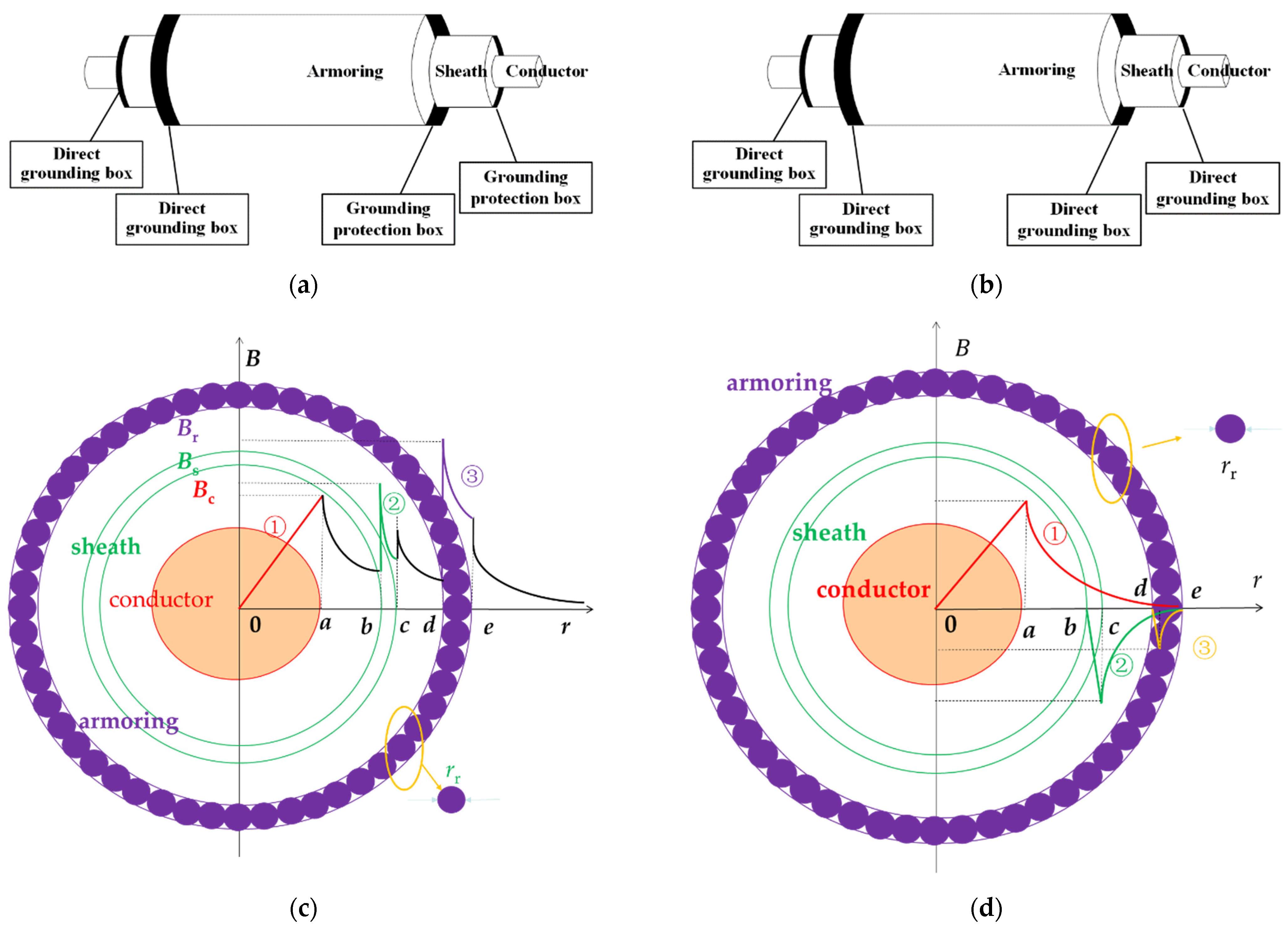
2.1. Structure of Single-Core AC Submarine Cable

For more than a century, various shapes and styles of submarine power cables have been invented, developed, manufactured, tested, and installed. Accordingly, many different requirements have been set for the design and manufacture of submarine cables. The structure of a single-core submarine cable is shown in Figure 1. The specific structure of a single-core submarine cable has been applied in offshore wind power plants in China, as illustrated in Table 1. These data are from reference [24].

2.2. Magnetic Field Analysis of Single-Core AC Submarine Cable under Different Outer Sheath Grounding Methods

There are two main outer sheath grounding methods for single-core AC submarine cable:

2.2.1. Single-End Grounding of the Outer Sheath

One end of the metallic sheath and armoring is grounded through the direct grounding box, and the other end of the metallic sheath and armoring is grounded through the grounding protection box. This grounding method is shown in Figure 2a.
This grounding method can greatly reduce the circulating current on the outer sheath of the single-core AC submarine cable and improve its service life and safe operation reliability, but the induced voltage of the metallic sheath and armoring is increased. The outer sheath of this grounding method is similar to the lifting pedestal of the transformer. The relationship between the magnetic field intensity B and the section radius of the different cable media r is shown in Equation (1), and the magnetic induction intensity of the single-core AC submarine cable is shown in Figure 2c.
{ B c = μ 0 I c 2 π a 2 r , r < a B i = μ 0 I c 2 π r , a < r b B s = μ s r μ 0 I c 2 π r , b < r c B p = μ 0 I c 2 π r , c < r d B r = μ r r μ 0 I c 2 π r , d < r e B z = μ 0 I c 2 π r , r > e
where Bc is the magnetic induction intensity of the conductor, Bi is the magnetic induction intensity of the insulation, Bs is the magnetic induction intensity of the sheath, Bp is the magnetic induction intensity of the packing layer, Br is the magnetic induction intensity of the armoring, Bz is the magnetic induction intensity of the air, a is the radius of the conductor, b is the outer radius of the insulation, c is the outer radius of the sheath, d is the outer radius of the packing layer, e is the outer radius of the armor, μ0 is the permeability of the vacuum, μsr is the relative permeability of the sheath, μrr is the relative permeability of the armoring, and Ic is the current of the conductor.

2.2.2. Both-End Grounding of the Outer Sheath

Both ends of the metallic sheath and armoring are grounded through the direct grounding box. This grounding method is shown in Figure 2b.
The metallic sheath and armoring of the single-core submarine cable are grounded by both ends in order to suppress the influence of the induced voltage, and the alternating magnetic field around the conductor generates a circulating current in the metallic sheath and armoring. The circulating current of a single-core AC submarine cable can reach the maximum conductor current, which will cause cable loss and overheating and affect the transmission capacity and service life of the cable line. The outer sheath of this grounding method is similar to the enclosed busbar of the generator-transformer unit. The relationship between the magnetic field intensity B and the section radius of the different cable media r is shown in Equation (2), and the magnetic induction intensity of the single-core AC submarine cable is shown in Figure 2d.
{ B c = μ 0 I c r 2 π a 2 , r < a B i = μ 0 I c 2 π r 2 , a r < b B s = μ s r μ 0 2 π r [ I c ( r 2 b 2 ) ( c 2 b 2 ) I s ] , b r < c B p = μ 0 ( I c I s ) 2 π r , c r < d B r = μ r r μ 0 2 π r [ I c I s ( r 2 d 2 ) ( e 2 d 2 ) I r ] , d r < e B z = 0 , e > 0
where Is is the current of the cable sheath, and Ir is the current of the cable armoring.

3. Characteristic Analysis of Outer Sheath Circulating Current in Single-Core AC Submarine Cable System

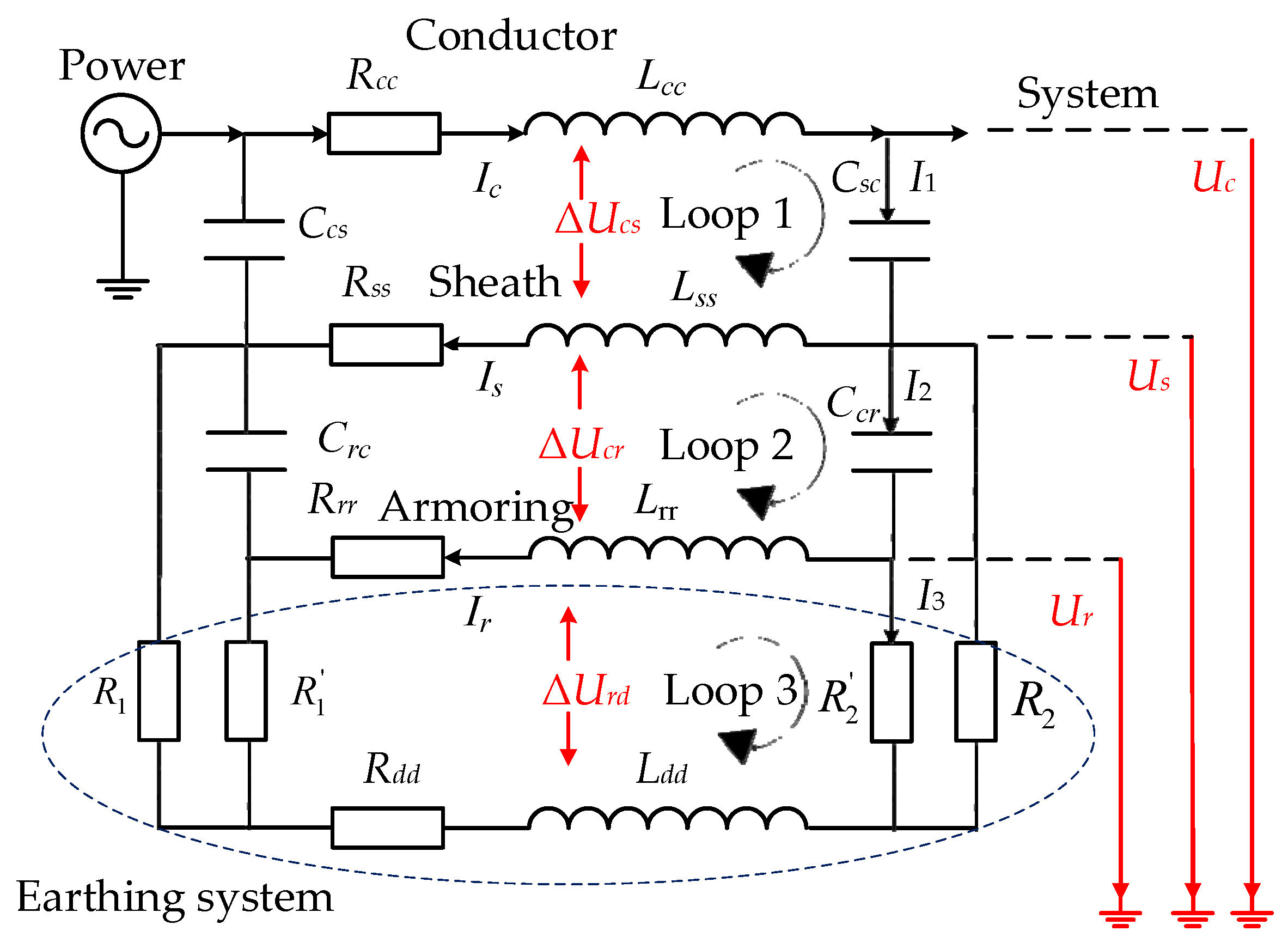
3.1. Shielding Transmission Impedance of Single-Core Submarine Cable

The equivalent circuit diagram of the single-core AC submarine cable is shown in Figure 3. Shielding transmission impedance links the conductor current, the sheath current and the armoring current.
Z i j = Δ U i j I j
We determined that both ends of the metallic sheath and armoring should be grounded through the direct grounding box in the remote distance submarine cable transmission system. However, the circulating current of the sheath and armoring has an impact on cable operation. The alternating conductor current Ic induces reverse currents on the sheath and armoring. The magnetic field generated by Ic counteracts that generated by the circulating currents on the sheath and armoring.
In Figure 3, Rcc represents the self-impedance of the conductor, Rss represents the self-impedance of the sheath, Rrr represents the self-impedance of the armoring, Rdd represents the self-impedance of the earthing system, Lcc represents the self-inductor of the conductor, Lss represents the self-inductor of the sheath, Lrr represents the self-inductor of the armoring, Ldd represents the self-inductor of the earthing system, Ccs represents the capacitance between the conductor layer and the sheath layer, Csr represents the capacitance between the sheath layer and the armoring layer, Crd represents the capacitance between the armoring layer and the earthing system layer, Ri represents ground resistance under different conditions, ΔUcs represents the voltage from the conductor to the sheath, ΔUsr represents the sheath to the armoring, ΔUrd represents the armoring to the ground, Uc represents the voltage from the conductor to the ground, Us represents the voltage from the sheath to the ground, Ur represents the voltage from the armoring to the ground, I1 represents the current of Loop 1, I2 represents the current of Loop 2, and I3 represents the current of Loop 3.
The induced voltage between the conductor and the sheath ΔUcs pulls ahead of the conductor current Ic by 90° using the formula for the induced voltage, which is ΔUcs = jwMc-sIc. The circulating current Is is lagged by ΔUcs through sheath resistance Rs and inductance Ls. As a result, the mode of Ic + Is is smaller than that of Ic. If the geometric center of the sheath circulating current Is coincides with the conductor current Ic, Is + Ic is the current acting on the armoring. The induced voltage between the sheath and the armoring ΔUsr pulls ahead of the current Is + Ic by 90° using the formula for the induced voltage, namely ΔUsr = jwMs,c-r(Is + Ic). The circulating current Ir is lagged by ΔUsr through the armoring resistance Rr and inductance Lr. A phasor diagram of the conductor current and sheath circulating current is shown in Figure 4.

3.2. Shielding Transmission Impedance Characteristic of Single-Core Submarine Cable

The cable parameters of the coaxial arrangement were derived in the form of equations for coaxial loops [12,13]. Loop 1 is formed by the conductor C and the metallic sheath S as return, and Loop 2 by the metallic sheath S and metallic armoring R as return, and finally, Loop 3 by the armoring R and either earth or seawater as return. It should be noted that mutual impedances exist among all three conductors. The sheath and armoring are normally bonded to the ground in a certain manner.
R 1 = ρ e 2 π L [ ln ( 4 L r ) 1 ] , Ω
where ρe represents the average sea mud resistivity, and L and r represent the length and radius of the rod, respectively, in meters.
R 2 = ρ c 2 π L [ ln ( 2 L 2 w h ) 1 ] , Ω
where L is the length of the strip or wire, h is the depth, w is the width of the strip or the diameter of the round wire, and ρc is the average soil resistivity.
The series impedances of the three loops are described using three coupled equations. The three coupled equations are given in Equation (6).
[ Δ U c s Δ U s r Δ U r d ] = [ Z 11 , Z 12 , 0 Z 21 , Z 22 , Z 23 0 , Z 32 , Z 33 ] [ I 1 I 2 I 3 ]
The relationship between the voltages of the three loops and the voltages from the conductor to the ground is expressed in Equation (7).
{ Δ U c s = U c U s Δ U s r = U s U r Δ U c r = U r
The relationship between the currents of the three loops and the current from the conductor to the ground is given by Equation (8).
{ I 1 = I c I 2 = I s + I c I 3 = I r + I s + I c
According to Equations (6)–(8), the mathematical equations representing the voltages and currents along the submarine cable are expressed in Equation (9).
[ Δ U · c s Δ U · s r Δ U · r d ] = [ Z c c , Z c s , Z c r Z s c , Z s s , Z s r Z r c , Z s c , Z r r ] [ I · c I · s I · r ]
The impedance matrix is given by Equation (10).
{ Z c c = Z 11 + 2 Z 12 + Z 22 + 2 Z 23 + Z 33 Z c s = Z s c = Z 12 + Z 22 + 2 Z 23 + Z 33 Z s r = Z r s = Z 23 + Z 33 Z s s = Z 22 + 2 Z 23 + Z 33 Z r r = Z 33
The parameter relationship for the circulating current of the sheath and armoring is given by Equation (11).
φ i j = I i I j = f ( Z i j , Z 1 , Z 2 , μ r )
where i, j represent the conductor c, sheath s, armoring r.
The calculation results of φij are identical to the simulation results in Section 4.

4. Circulating Current Analysis of Sheath and Armoring under the Different Material Characteristic Conditions by Simulation

The stationary time model is obtained with the sections of the power transmission system that include the current source, three-phase single-core AC submarine cable, and electricity load. The external characteristics of the power transmission system are shown as the voltage class 220 kV, a maximum transmission capacity of 300 MW. The parameters and structures of the submarine cable in Table 1 and Figure 1 are considered in the stationary time model. More influence factors for the conductor current of single-core AC submarine cables are considered in the stationary time model and simulation. The results, which are combined with the analysis of transmission impedance in Section 3, indicated that the different levels of magnetic conductivity, resistivity, and ground resistance have a relatively great influence on the distribution of the outer sheath circulating current. The overall analysis was performed using ATP-EMTP software. The simulation model and partial results are shown in Figure 5.

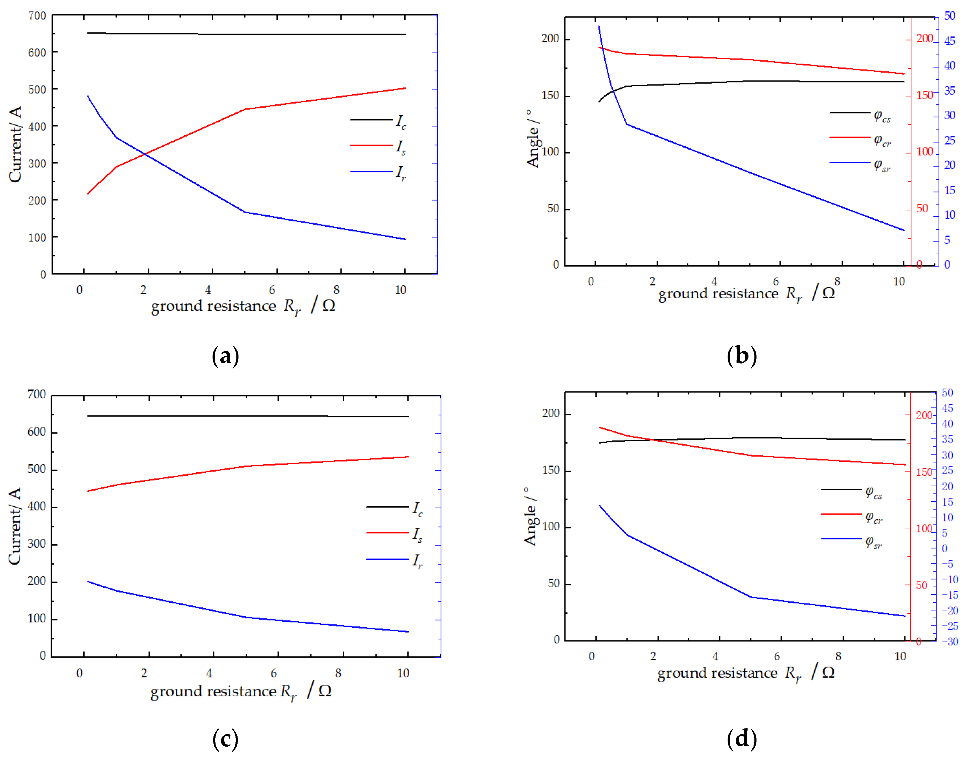
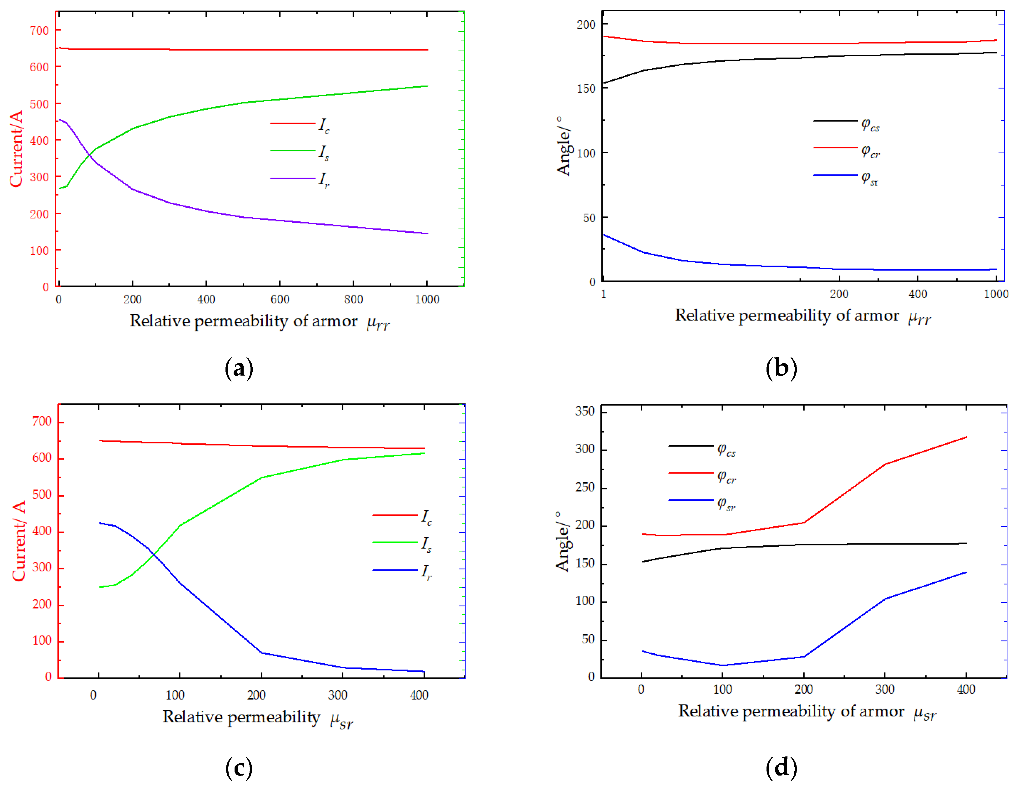
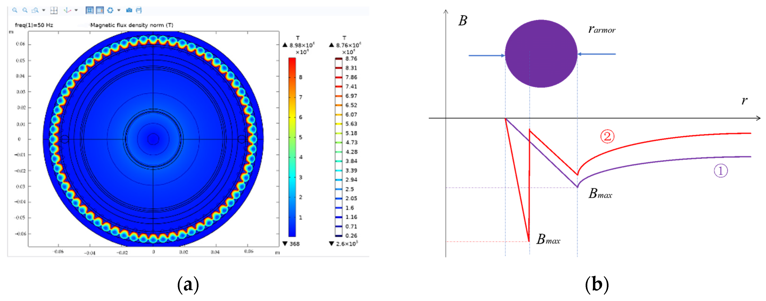
4.1. Circulating Current of the Sheath and Armoring under the Different Magnetic Conductivity Conditions

Under different magnetic armoring permeability conditions, Ic remains unchanged. Is increases as the magnetic permeability of armoring increases. Ir decreases as the magnetic permeability of armoring increases. The relationship between the currents of armoring and the magnetic permeability of armoring is shown in Figure 6a.
The phase difference between the conductor current and sheath current φcs increases with increasing permeability, and φcs changes from 154.04° to 177.65°. The phase difference between the conductor current and armoring current φcr decreases as the magnetic permeability of the armoring increases, and φcr changes from 190.36° to 187.22°. The phase difference between the sheath current and armoring current φsr decreases as the magnetic permeability of the armoring increases, and φsr changes from 36.32° to 9.57°. Obviously, the material properties of the armoring change from nonmagnetic to magnetic. The relationship between the phase difference and the magnetic permeability of armoring is shown in Figure 6b.
Under different magnetic sheath permeability conditions, Ic remains unchanged. Is increases as the magnetic permeability of the sheath increases. Ir decreases as the magnetic permeability of the sheath increases. The relationship between the currents and the magnetic permeability of the sheath is shown in Figure 6c.
The phase difference between the conductor current and sheath current φcs increases with increasing permeability, and φcs changes from 154.04° to 177.93°. The phase difference between the conductor current and armoring current φcr decreases as the magnetic permeability of the armoring increases, and φcr changes from 190.36° to 318.15°. The phase difference between the sheath current and armoring current φsr remains the same, and then φsr increases as the magnetic permeability of the armoring increases, and φsr changes from 36.32° to 140.22°. There are obvious changes in phase difference, namely, the material of the armoring changes from nonmagnetic to magnetic. The relationship between the phase difference and the magnetic permeability of the sheath is shown in Figure 6d.

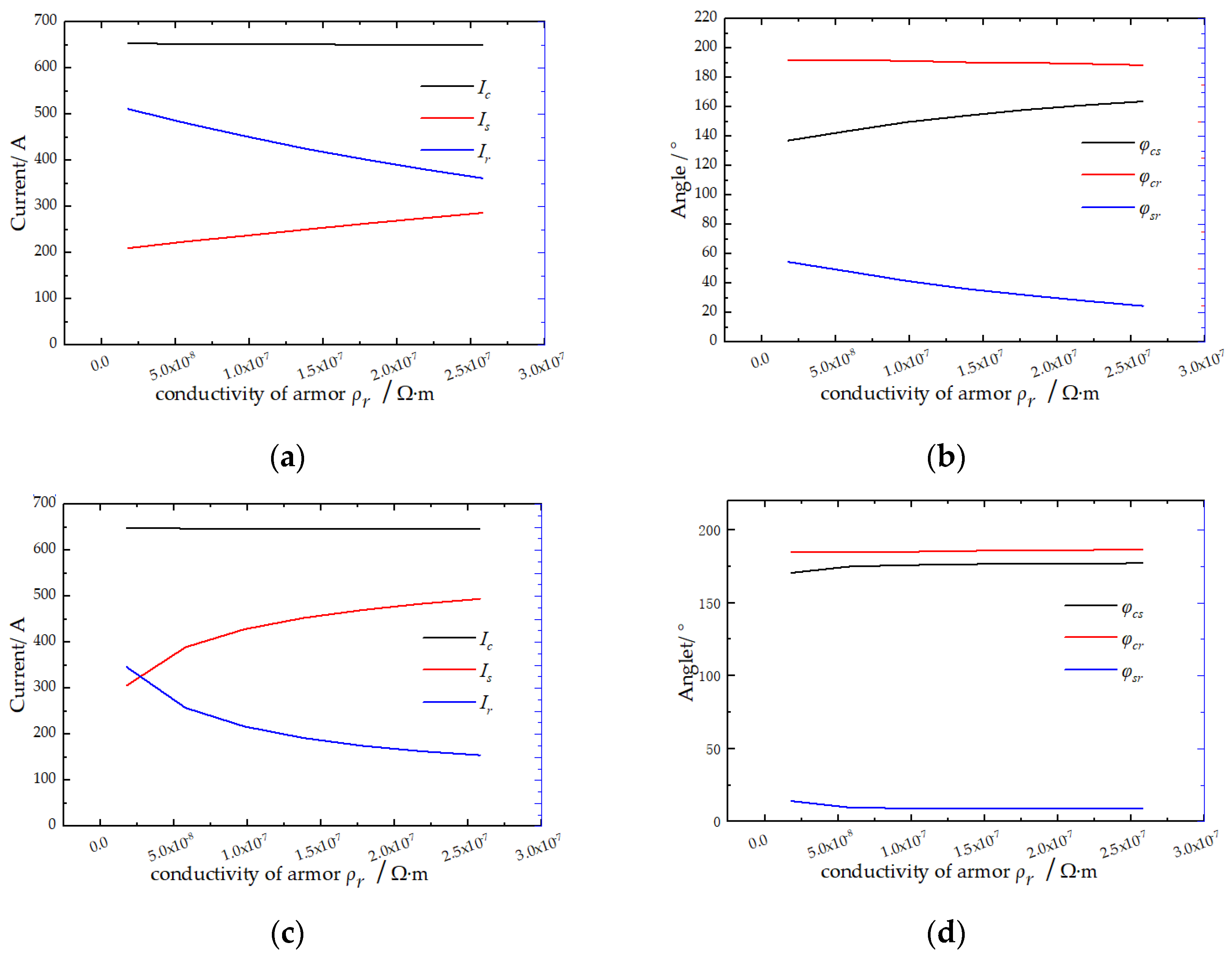
4.2. Circulating Current of Sheath and Armoring under Different Resistivity Conditions

Under different resistivity levels of the nonmagnetic armoring conditions, Ic remains unchanged. Is increases as the resistivity of the nonmagnetic armoring increases. Ir decreases with increases in the resistivity of the nonmagnetic armoring. The relationship between the current and the resistivity of the nonmagnetic armoring is shown in Figure 7a.
The phase difference between the conductor current and sheath current φcs increases as the resistivity of the nonmagnetic armoring increases, and φcs changes from 137.17° to 163.78°. The phase difference between the conductor current and armoring current φcr remains unchanged. The phase difference between the sheath current and armoring current φsr decreases as the resistivity of the nonmagnetic armoring increases, and φsr changes from 54.61° to 24.66°. The relationship between the phase difference and the resistivity of nonmagnetic armoring is shown in Figure 7b.
Under different resistivities of the magnetic armoring condition, Ic remains unchanged. Is increases as the resistivity of the magnetic armoring increases. Ir decreases as the resistivity of the magnetic armoring increases. The relative magnetic permeability is 400. The relationship between the currents and the resistivity of magnetic armoring is shown in Figure 7c.
The phase difference between the conductor current and sheath current φcs increases as the resistivity of the magnetic armoring increases, and the change in φcs is not great, from 170.77° to 177.37°. The phase difference between the conductor current and armoring current φcr remains unchanged. The phase difference between the sheath current and armoring current φsr decreases as the resistivity of the nonmagnetic armoring increases, and the variation of φsr is not great, from 14.13° to 9.11°. The relationship between the phase difference and the resistivity of the nonmagnetic armoring is shown in Figure 7d.

4.3. Circulating Current of Sheath and Armoring under Different Ground Resistance Conditions

Under the different ground resistances of the nonmagnetic armoring conditions, Ic remains unchanged. Is increases as the ground resistance of the nonmagnetic armoring increases. Ir decreases as the ground resistance of nonmagnetic armoring increases. The relationship between the currents and the ground resistance of nonmagnetic armoring is shown in Figure 8a.
The phase difference between the conductor current and sheath current φcs increases as the ground resistance of the nonmagnetic armoring increases, and φcs changes from 145.51° to 162.97°. The phase difference between the conductor current and armoring current φcr decreases as the ground resistance of the nonmagnetic armoring increases, and φcr changes from 190.73° to 170.19°. The phase difference between the sheath current and armoring current φsr decreases as the ground resistance of the nonmagnetic armoring increases, and φsr changes from 48.22° to 7.218°. The relationship between the phase difference and the ground resistance of the nonmagnetic armoring is shown in Figure 8b.
Under different ground resistances of the magnetic armoring conditions, Ic remains unchanged. Is increases as the ground resistance of the magnetic armoring increases, and Ir decreases as the ground resistance of the magnetic armoring increases. The relative magnetic permeability is 400. The relationship between the currents and the ground resistance of magnetic armoring is shown in Figure 8c.
The phase difference between the conductor current and sheath current φcs increases as the ground resistance of the magnetic armoring increases, and the change of φcs is not great, from 173.42° to 177.97°. The phase difference between the conductor current and armoring current φcr decreases as the ground resistance of the magnetic armoring increases, and the variation of φcr changes from 189.01° to 156.04°. The phase difference between the sheath current and armoring current φsr decreases as the ground resistance of the magnetic armoring increases, and the variation of φsr is not obvious, from 13.59° to −21.88°. The relationship between the phase difference and the ground resistance of the magnetic armoring is shown in Figure 8d.

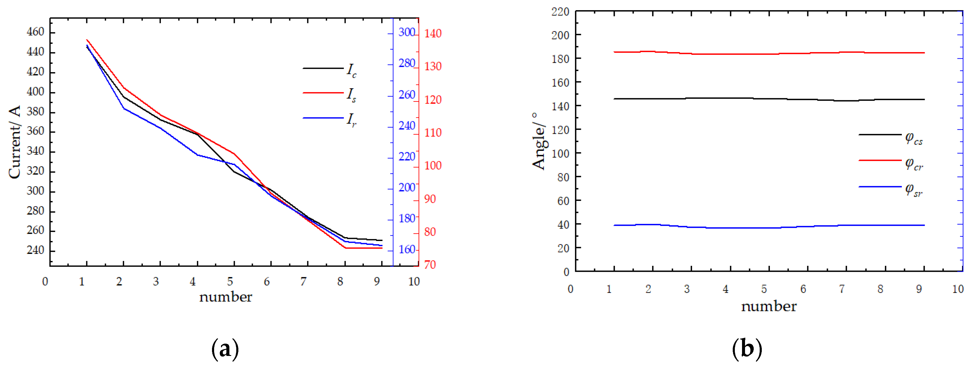
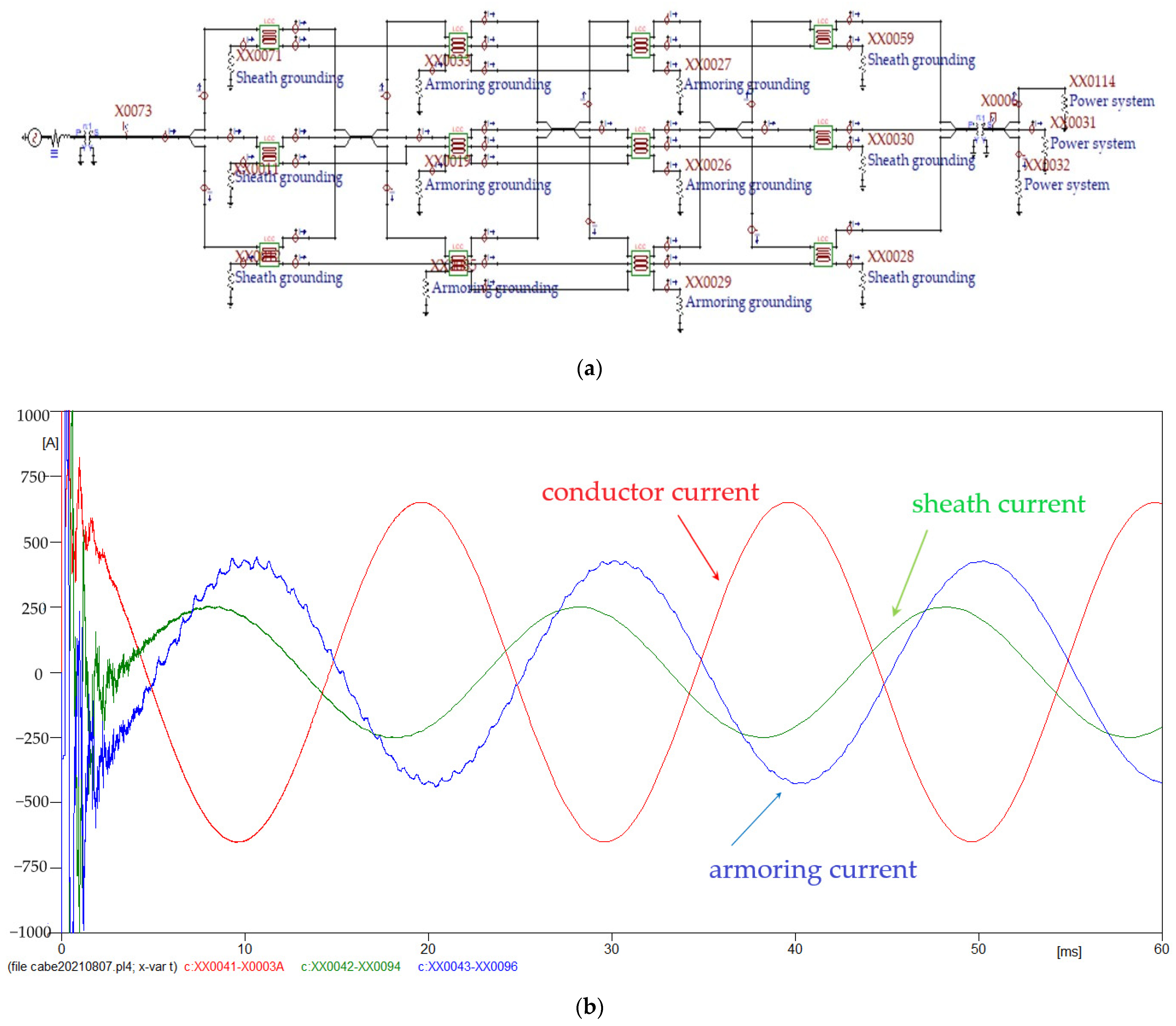
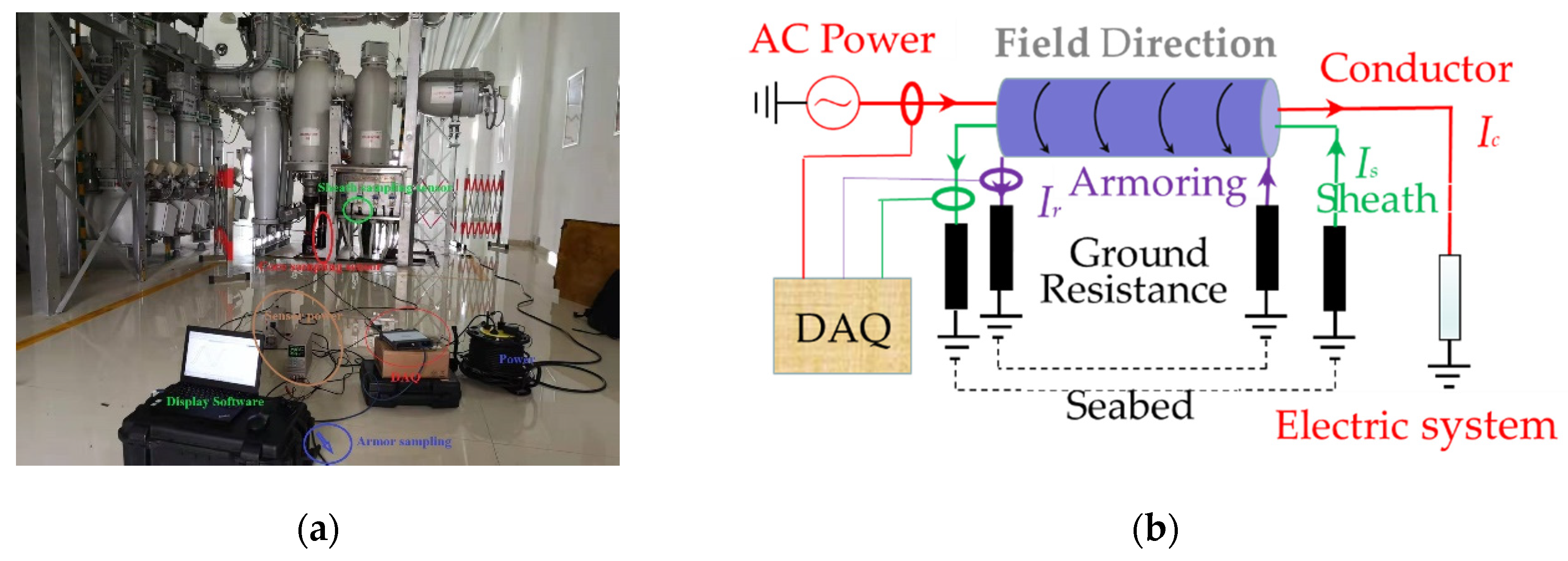
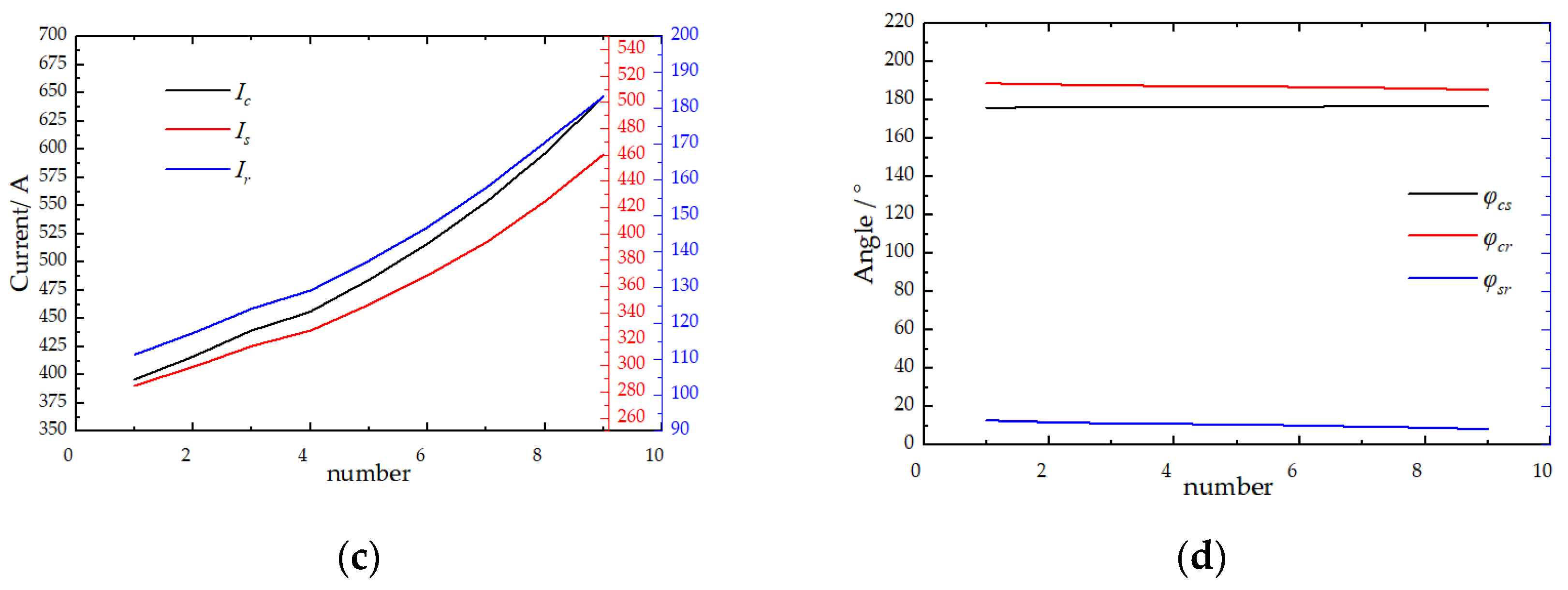
5. Engineering Case Analysis

A Chinese offshore wind power plant had an installed capacity of 300 MW. It was pooled through 35 kV to the offshore booster station, and the 35 kV voltage was increased to 220 kV by a boosting transformer. Wind power was transmitted to the terrestrial substation through three 220 kV single-core submarine cables. The route of the submarine cable consisted of five sections and is shown in Figure 9. The route and the particulars of the single-core AC submarine cables are listed in Table 2 [24].
The sheath and armoring of the submarine cable were grounded by both ends in order to suppress the influence of induced voltage. As the materials of the sheath outer layer were semiconducting PE, the sheath and armoring of the submarine cable should be treated as multipoint earthing in the sea. The sheath and armoring of the submarine cable of Sections II, III, and IV were treated as multipoint earthing submerged in the sea. The sheath and armoring of the submarine cable of Sections I and V were treated as two-point earthing.
As shown in Figure 10, the proposed methodology was used to obtain a flowchart of the acquisition of the submarine cable current and phase difference. The currents were monitored in the long term, including the conductor current, and the grounding currents of the sheath and armoring. Current sensors were similar to zero-flux current transformers with a power supply.
Under different load conditions, the operating current of the terrestrial substation was monitored using the proposed methodology, and the nine current operating data of the terrestrial substation and offshore booster station were monitored. Ic was positively correlated with Is, and Ir. The data of the terrestrial substation are shown in Figure 11a, and those of the offshore booster station are shown in Figure 11c.
The phase difference of the submarine cable was unchanged under the different load conditions in the terrestrial substation, and φcs was approximately 146°, and φcr was approximately 185°, and φsr was approximately 39°. The phase difference data of the submarine cable are shown in Figure 11b.
The phase difference of the submarine cable was unchanged under the different load conditions in the offshore booster station: φcs was approximately 176°, φcr was approximately 186°, and φsr was approximately 9.7°. The phase difference data of the submarine cable are shown in Figure 11d.
The above operating data revealed that the sheath current of the terrestrial substation and those of the onshore booster station were respectively asymmetric, and the armoring currents showed the same characteristics. The addition of copper wire to the armoring and magnetic isolation was largely equivalent to the permeability of changing the direction of the armoring section. In this method, the armored steel wire was made of copper wire, and the tangential permeability of the armoring was changed by replacing the copper wire. In view of the skin effect, the magnetic field induction lines were tightly arranged in the inner ring of the armoring. The effective cross-sectional area of the armoring was reduced to ensure the flow of the induction current. The magnetic resistance and induction current of armoring were increased and decreased, respectively. The magnetic field and its intensity of armoring are shown in Figure 12. Owing to the skin effect, the Br changed from curve ① to curve ②. The properties of armoring could hardly be determined by the alternating current of the sheath and armoring, but they could be easily determined by the phase difference of the sheath current and armoring current φsr. The finding suggested that the phase differences between the conductor current and the sheath current, the conductor current and the armoring current, and the sheath current and the armoring current should determine the material properties for each section of submarine cable through theoretical analysis, simulation, and experiment.

6. Conclusions

Aiming to discover the influence factors of the circulating current in the sheath and armoring, we proposed a method to evaluate and analyze the circulating current of the sheath and armoring using the transmission impedance characteristics. The conclusions are as follows:
  • The outer sheaths of a single-core AC submarine cable have different electromagnetic characteristics under the two grounding forms. We clearly explained the formation mechanism for the circulating current of the outer sheath. The outer sheaths are grounded through both ends, which exhibits a shielding effect whereby the magnetic field direction generated by the circulating current of the outer sheath is opposite to the magnetic field direction generated by the conductor current in the single-core AC submarine cable.
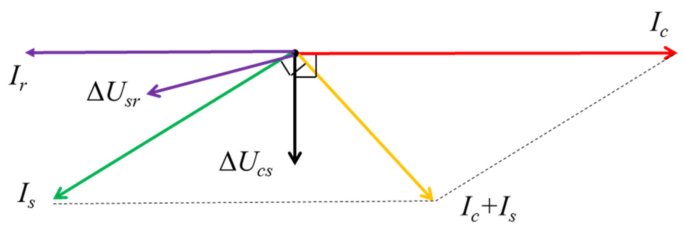
  • A detailed equivalent circuit model of a single-core AC submarine cable was presented to facilitate the analysis of the circulating current of the outer sheaths. The impedance matrix was proposed from three coaxial circuit equations, and the phase difference determining the material properties of each metallic section was proposed.
  • We proved by numerical simulation, simulation calculation, and field verification that influence factors such as permeability, resistivity, and ground resistance of the outer sheath layers will affect the symmetrical distribution of the circulating current of the outer sheath. The distribution of the circulating current on the outer sheath is negatively correlated with permeability, resistivity, and ground resistance. The results must be considered in the stage of submarine cable design and selection.
This paper proposes a method for evaluating the circulating current of the outer sheath that can provide a direction for the loss research of single-core AC submarine cable. On this basis, the method of evaluating the loss of the three-core AC submarine cable and direct current submarine cable needs to be further studied. In the future, we must continue to study the insulation performance of the single-core AC submarine cable by transmission impedance characteristics.

Author Contributions

Conceptualization, P.L. and P.G.; methodology, P.L.; software, P.L.; validation, P.L. and P.G; formal analysis, P.L.; investigation, P.L.; resources, P.L.; data curation, P.L. and P.G.; writing—original draft preparation, P.L. and P.G.; writing—review and editing, P.L. and P.G. All authors have read and agreed to the published version of the manuscript.

Funding

This research received no external funding.

Institutional Review Board Statement

Not applicable.

Informed Consent Statement

Not applicable.

Data Availability Statement

Not applicable.

Conflicts of Interest

The authors declare no conflict of interest.

References

  1. Soares-Ramos, E.P.; Assis, L.D.O.; Sarrias-Mena, R.; Fernández-Ramírez, L.M. Current status and future trends of offshore wind power in Europe. Energy 2020, 202, 117787. [Google Scholar] [CrossRef]
  2. Taormina, B.; Bald, J.; Want, A.; Thouzeau, G.; Lejart, M.; Desroy, N.; Carlier, A. A review of potential impacts of submarine power cables on the marine environment: Knowledge gaps, recommendations and future directions. Renew. Sustain. Energy Rev. 2018, 96, 380–391. [Google Scholar] [CrossRef]
  3. Worzyk, T. Submarine Power Cables: Design, Installation, Repair, Environmental Aspects; Springer: New York, NY, USA, 2009; Volume 1, pp. 10–48. [Google Scholar] [CrossRef]
  4. Bianchi, G.; Luoni, G. Induced currents and losses in single-core submarine cables. IEEE Trans. Power Appar. Syst. 1976, 95, 49–58. [Google Scholar] [CrossRef]
  5. 575-1988; An American National Standard IEEE guide for the Application of Sheath-Bonding Methods for Single-Conductor Cables and The Calculation of Induced Voltages and Cur-Rents in Cable Sheaths. ANSI: New York, NY, USA; IEEE: Piscataway, NJ, USA, 1987. [CrossRef]
  6. IEC 60287-1-1; International Electrotechnical Commission. Electric Cables—Calculation of the Current Rating—Part 1-1: Current Rating Equations (100% Load Factor) and Calculation of Losses. HIS: Geneva, Switzerland, 2006.
  7. IEC 60287-2-1; International Electrotechnical Commission. Electric Cables—Calculation of the Current Rating—Part 2-1: Thermal Resistance—Calculation of Thermal Resistance. HIS: Geneva, Switzerland, 2006.
  8. IEC 60287-3-1; International Electrotechnical Commission. Electric Cables—Calculation of the Current Rating—Part 3-1: Sections on Operating Conditions—Reference Operating Conditions and Selection of Cable Type. HIS: Geneva, Switzerland, 1999.
  9. Barrett, J.; Anders, G. Circulating current and hysteresis losses in screens, sheaths and armor of electric power cables-mathematical models and comparison with IEC Standard 287. IEE Proc. Sci. Meas. Technol. 1997, 144, 101–110. [Google Scholar] [CrossRef]
  10. Fan, Y.; Liu, S.; Deng, X. Study on the ampacity of single-core submarine power cable with return conductor. In Proceedings of the IOP Conference Series: Materials Science and Engineering, Changsha, China, 19–21 April 2019; Volume 563. [Google Scholar] [CrossRef]
  11. Wagenaars, P.; Wouters, P.A.F.; Van Der Wielen, P.J.M.; Steennis, E. Approximation of transmission line parameters of single-core and three-core XLPE cables. IEEE Trans. Dielectr. Electr. Insul. 2010, 17, 106–115. [Google Scholar] [CrossRef] [Green Version]
  12. Wagenaars, P.; Steennis, E.; Wouters, P.; van der Wielen, P. Measurement of transmission line parameters of three-core power cables with common earth screen. IET Sci. Meas. Technol. 2009, 4, 146–155. [Google Scholar] [CrossRef] [Green Version]
  13. Shaban, M.; Salam, M.; Ang, S.; Voon, W. Induced sheath voltage in power cables: A review. Renew. Sustain. Energy Rev. 2016, 62, 1236–1251. [Google Scholar] [CrossRef]
  14. Schelkunoff, S.A. The Electromagnetic Theory of Coaxial Transmission Lines and Cylindrical Shields. Bell Syst. Tech. J. 1934, 13, 532–579. [Google Scholar] [CrossRef]
  15. Wang, X.H.; Song, Y.H.; Jung, C.K. Tackling sheath problems: Latest research developments in solving operational sheath problems in underground power transmission cables. Electr. Power Syst. Res. 2007, 77, 1449–1457. [Google Scholar] [CrossRef]
  16. Liu, G.; Fan, M.; Wang, P.; Zheng, M. Study on Reactive Power Compensation Strategies for Long Distance Submarine Cables Considering Electrothermal Coordination. J. Mar. Sci. Eng. 2021, 9, 90. [Google Scholar] [CrossRef]
  17. Candela, R.; Gattuso, A.; Mitolo, M.; Sanseverino, E.R.; Zizzo, G. Model for Assessing the Magnitude and Distribution of Sheath Currents in Medium and High Voltage Cable Lines. IEEE Trans. Ind. Appl. 2020, 56, 6250–6257. [Google Scholar] [CrossRef]
  18. Papazyan, R.; Pettersson, P.; Edin, H.; Eriksson, R.; Gafvert, U. Extraction of high frequency power cable characteristics from S-parameter measurements. IEEE Trans. Dielectr. Electr. Insul. 2004, 11, 261–270. [Google Scholar] [CrossRef]
  19. De Wulf, M.; Wouters, P.; Sergeant, P.; Dupré, L.; Hoferlin, E.; Jacobs, S.; Harlet, P. Electromagnetic shielding of high-voltage cables. J. Magn. Magn. Mater. 2007, 316, 908–911. [Google Scholar] [CrossRef]
  20. Bremnes, J.; Evenset, G.; Ronny, S. Power Loss and Inductance of Steel Armoured Multi-Core Cables: Comparison of IEC Values with ‘2.5D’ FEA Results and Measurements; paper B1_116; CIGRÉ: Paris, France, 2010. [Google Scholar]
  21. Clayton, R.P. Analysis of Multiconductor Transmission Lines, 2nd ed.; John Wiley & Sons, Inc.: Hoboken, NJ, USA, 2008; pp. 89–109. [Google Scholar]
  22. Wedepohl, L.; Wilcox, D. Transient analysis of underground power-transmission systems: System-model and wave-propagation characteristics. Proc. IEE 1973, 120, 252–259. [Google Scholar] [CrossRef]
  23. Gu, J.; Liu, Z. TOPSIS-Based Algorithm for Resilience Indices Construction and the Evaluation of an Electrical Power Transmission Network. Symmetry 2022, 14, 985. [Google Scholar] [CrossRef]
  24. Yang, Z. The Procurement Technical Agreement of 220 kV Single-Core Submarine Cable in the 300 MW Offshore Wind Power Project; Zhong-tian Technology Group Co., Ltd.: Nanjing, China, 2016. [Google Scholar]
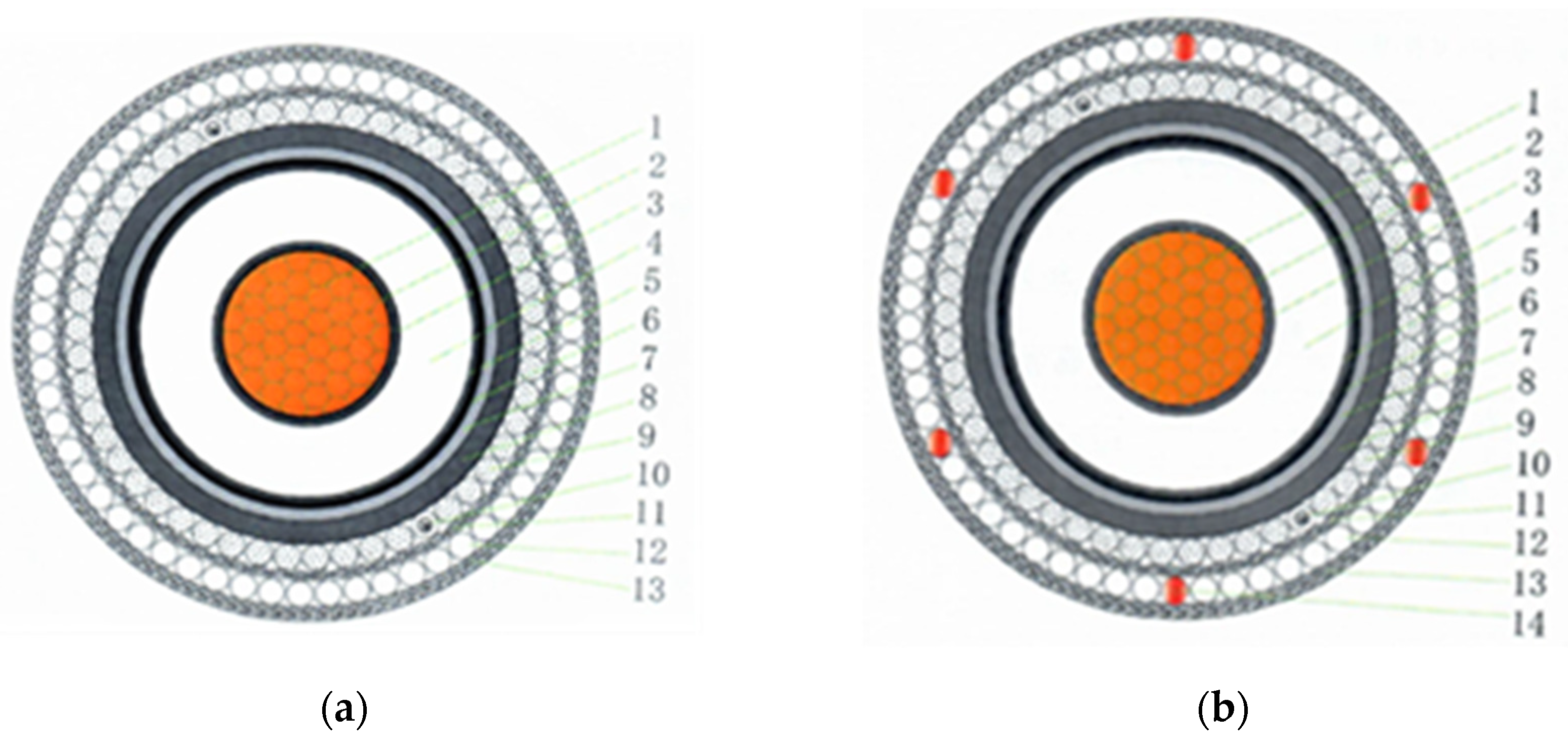
Figure 1. Structure diagram of a single-core submarine cable. (a) The armoring made of 66 galvanized steel wire; and (b) the armoring made of 60 galvanized steel wire and 6 copper wire.
Symmetry 14 01088 g001
Figure 2. Cable grounding mode and magnetic induction intensity diagram. (a) The grounding diagram for single-end grounding of the outer sheath; (b) the grounding diagram for both-end grounding of the outer sheath; (c) the magnetic induction intensity for single-end grounding of the outer sheath; and (d) the magnetic induction intensity for both-end grounding of the outer sheath. Curve ① indicates the magnetic field intensity of the conductor, and curve ② indicates the magnetic field intensity of the sheath, and curve ③ indicates the magnetic field intensity of the armoring.
Symmetry 14 01088 g002
Figure 3. Equivalent circuit diagram of the single-core AC submarine cable.
Symmetry 14 01088 g003
Figure 4. Phasor diagram of conductor current and outer sheath circulating current.
Symmetry 14 01088 g004
Figure 5. The simulation model and partial results of the submarine cable. (a) Simulation model of a three-phase single-core AC submarine cable; and (b) simulation partial result of a single-core AC submarine cable, where the red curve represents the conductor current, the green curve represents the sheath current, and the blue curve represents the armoring current.
Symmetry 14 01088 g005
Figure 6. Diagrams of the circulating current and phase difference of sheath and armoring under different magnetic permeability conditions. (a) Diagram of the circulating current of the sheath and armoring under different levels of magnetic permeability of the armoring; (b) diagram of the phase difference of the sheath and armoring under different levels of magnetic permeability of the armoring; (c) diagram of the circulating current of the sheath and armoring under different levels of magnetic permeability of the sheath; and (d) diagram of the phase difference of the sheath and armoring under different levels of magnetic permeability of the sheath.
Symmetry 14 01088 g006
Figure 7. Diagrams of circulating current and phase difference of sheath and armoring under different resistivity conditions. (a) Diagram of the circulating current of the sheath and armoring under different resistivities of the nonmagnetic armoring; (b) diagram of the phase difference of the sheath and armoring under different resistivities of the nonmagnetic armoring; (c) diagram of the circulating current of the sheath and armoring under different resistivities of the magnetic armoring; and (d) diagram of the phase difference of the sheath and armoring under different resistivities of the magnetic armoring.
Symmetry 14 01088 g007
Figure 8. Diagrams of the circulating current and phase difference of the sheath and armoring under different ground resistances of the nonmagnetic and magnetic armoring conditions. (a) Diagram of the circulating current of the sheath and armoring under different ground resistances of the nonmagnetic armoring; (b) diagram of the phase difference of the sheath and armoring under different ground resistances of the nonmagnetic armoring; (c) diagram of the circulating current of the sheath and armoring under different ground resistances of the magnetic armoring; and (d) diagram of the phase difference of the sheath and armoring under different ground resistances of the magnetic armoring.
Symmetry 14 01088 g008
Figure 9. The route diagram of the three-phase single-core AC submarine, divided into five sections in a Chinese offshore wind power plant. Section I presents the section from offshore booster station to seabed. Section II, Section III, and Section IV present the seabed section. Section V presents the section from seabed to terrestrial substation.
Symmetry 14 01088 g009
Figure 10. The flowchart diagram of the acquisition of the single-core AC submarine cable current and phase difference. (a) Field test image of the acquisition of the single-core AC submarine cable current and phase difference; and (b) schematic figure of the acquisition of the single-core AC submarine cable current and phase difference. DAQ is the Data Acquisition Card and display software.
Symmetry 14 01088 g010
Figure 11. Diagrams of field test data of the terrestrial substation and offshore booster station current and phase difference in the single-core AC submarine cable. (a) Diagram of field test data of the terrestrial substation current in the single-core AC submarine cable; (b) diagram of field test data of the terrestrial substation phase difference in the single-core AC submarine cable; (c) diagram of field test data of the offshore booster station current in the single-core AC submarine cable; and (d) diagram of field test data of the offshore booster station phase difference in the single-core AC submarine cable.
Symmetry 14 01088 g011aSymmetry 14 01088 g011b
Figure 12. Cloud and curve diagrams of the magnetic field intensity of the armoring. (a) Cloud diagram of the magnetic field intensity of the magnetic armoring; and (b) curve diagram of the magnetic field intensity of the nonmagnetic and magnetic armoring; curve ① indicates the magnetic field intensity of the nonmagnetic armoring, and curve ② indicates the magnetic field intensity of the magnetic armoring.
Symmetry 14 01088 g012
Table 1. Parameters of a Single-Core Submarine Cable.
NoStructureThicknessNominal Outside DiameterMaterial PropertyVolume Resistivity
1Conductor 17.1 mmCopper1.7241 × 10−8 Ω·m
2Conductive package2 × 0.25 mm17.6 mmSemiconducting polyethylene (PE)<1000 Ω·m
3Conductor shielding1.5 mm19.1 mmSemiconducting PE<1000 Ω·m
4Insulation25 mm44.1 mmCross-Linked Polyethylene
5Insulative shielding1.2 mm45.3 mmSemiconducting PE<500 Ω·m
6Aquiclude layer2 × 0.5 mm46.3 mmSemiconducting PE<500 Ω·m
7Sheath3.9 mm50.2 mmLead alloy2.14 × 10−7 Ω·m
8Sheath outer layer3.4 mm53.6 mmSemiconducting PE<1000 Ω·m
9Packing layer5.0 ± 0.5 mm58.6 mm--
10Optical fiber unit----
11Armoring cushion layer1.5 ± 0.2 mm60.1Poly propylene-
12Armoring(66 ± 2) × Φ6.0 mm66.1 mmGalvanized steel wire1.38 × 10−7 Ω·m
13PP outer serving4.0 ± 0.5 mm70.1 mmPoly propylene-
14Armoring6 × Φ6.0 mm-Copper1.7241 × 10−8 Ω·m
Table 2. Tables showing the route and particulars of the single-core submarine cables.
Section of Submarine CableLength of the RouteStructure of Submarine Cable
I30 mFigure 1a, Table 1
II300 mFigure 1a, Table 1
III20 kmFigure 1a, Table 1
IV300 mFigure 1a, Table 1
V100 mFigure 1b, Table 1
I30 mFigure 1a, Table 1
Publisher’s Note: MDPI stays neutral with regard to jurisdictional claims in published maps and institutional affiliations.

