Review

A Survey of Battery–Supercapacitor Hybrid Energy Storage Systems: Concept, Topology, Control and Application

1
School of Electrical Engineering, Shandong University, Jinan 250100, China
2
Shenzhen Research Institute, Shandong University, Shenzhen 518057, China
3
State Grid Hebei Extra High Voltage Company, Shijiazhuang 050023, China
4
State Grid Shandong Integrated Energy Services Co., Ltd., Jinan 250001, China
*
Author to whom correspondence should be addressed.
Symmetry 2022, 14(6), 1085; https://doi.org/10.3390/sym14061085
Submission received: 14 April 2022 / Revised: 10 May 2022 / Accepted: 12 May 2022 / Published: 25 May 2022
(This article belongs to the Section Engineering and Materials)

Abstract

:
A hybrid energy-storage system (HESS), which fully utilizes the durability of energy-oriented storage devices and the rapidity of power-oriented storage devices, is an efficient solution to managing energy and power legitimately and symmetrically. Hence, research into these systems is drawing more attention with substantial findings. A battery–supercapacitor hybrid energy-storage system (BS-HESS) is widely adopted in the fields of renewable energy integration, smart- and micro-grids, energy integration systems, etc. Focusing on the BS-HESS, in this work we present a comprehensive survey including technologies of the battery management system (BMS), power conversion system (PCS), energy management system (EMS), predictive control techniques of the underlying system, application and cost-effective feasibility aspects, etc. This work reflects strong symmetry on different aspects of designing an HESS, and provides guidelines and design references for the research and application of an HESS.

1. Introduction

With the excessive consumption of global fossil energy and the increasing problem of environmental pollution [1], a new era of energy revolution, characterized by large-scale development and utilization of renewable energy and rapid development of new energy vehicles, is flourishing. However, renewable energy resources, represented by, e.g., wind and solar energy [2], will lead to fluctuations in power due to their intermittent characteristics. New energy vehicles [3,4], especially pure electric vehicles, require proper energy storage to guarantee a feasible operation. To solve the mentioned problems, energy-storage techniques, which are obligated to provide high energy-conversion efficiency, safe and healthy power storage, and economic feasibility, become the key [5].
Energy-storage devices can be divided into power-oriented and energy-oriented storage devices. The former, such as supercapacitors [6], superconductors [7], and flywheels, have the advantages of high power density and fast response speed, but with the disadvantage of low energy density. The latter, such as batteries [8] and pumped-storage hydroplants [9] have the advantage of high energy density, but with low power density and slow response speed. It is therefore difficult for a single energy-storage device to provide both high power and energy density, limiting the application scenarios. Therefore, it is necessary to combine two or more kinds of energy-storage devices, forming a hybrid energy-storage system (HESS), to provide a technical complementarity [10].
In recent years, the concept of an HESS consisting of two or more energy-storage devices has become a hotspot around the world [11]. Different from the energy-storage system consisting of a single energy-storage device, the HESS combines the characteristics of high power density, high energy density, and long operating life span [12,13], thus drawing wide attention. Recently, the HESS has been widely used in microgrids [14,15], urban rail transit [16,17], electric vehicles [18], and other fields.
Taking the battery–supercapacitor hybrid energy-storage system (BS-HESS) as the research object, the hot topics regarding the BS-HESS include (1) the fast, safe and low-cost battery management system (BMS); (2) the low-cost, free-flowing energy and multi-port power conversion system (PCS); (3) the reasonable and efficient energy management system (EMS); (4) the practical and high-performance control strategy.
In terms of the BMS, the energy equalization control scheme of an energy-storage battery pack is a key link, which is of great significance in terms of safe battery operation, efficiency improvement and service life extension, etc. In the early stage, the passive equalization scheme was mainly used, with simple control but serious energy dissipation. In the 1990s, the active equalization scheme was proposed, which reduced the energy dissipation and improved the equalization speed. Nowadays, the modular scheme is becoming a research hotspot and can further improve the practical performance. In terms of the PCS, with the development of new energy power generation and hybrid energy-storage system, the research perspective on multi-port power conversion systems has changed from small power to medium and high power, from bidirectional flow of power at partial ports to bidirectional flow of power at all ports, from discrete components to integrated circuits, and from non-isolated structures to partially isolated and fully isolated structures. EMS is the brain that manages the BS-HESS, and a reasonable energy management strategy can maximize the advantages of various types of energy-storage devices, further improving the total performance (efficiency, cost, etc.) of the system. The early strategies, such as threshold control, filter method and fuzzy control, are usually consistent with a certain rule, and the optimization process is more mechanized. Nowadays, the strategies have become more intelligent, and the optimization process has become more flexible. Thus, the performance is greatly improved. In addition, how to find the global optimum instead of the local optimum result is also a research hotspot. The latter relates to the practical and high-performance control strategy for a dual-active-bridge (DAB) converter, which is a typical converter and widely used in the BS-HESS. Recently, model predictive control (MPC) has been applied to DAB converters due to its excellent performance. In the early stage, MPC was applied in DAB converters with discrete control set (also known as finite control set); the DAB converter with MPC has low power density and it is hard to achieve soft switching. Nowadays, MPC for DAB converters is mainly combined with phase-shifting modulation and is based on a continuous control set, resulting in high power-density conversion and other excellent performance.
These issues mentioned above directly affect the cost, life cycle, and efficiency of the energy-storage system. However, a comprehensive survey of the BS-HESS is rarely reported. In this paper, we present a survey of the BS-HESS in terms of concept, topology, control and applications. Compared with other surveys, the main contributions of this paper include: (1) Classifying the energy equalization control scheme according to the symmetry of driving energy transmission, instead of the circuit structure. (2) Comparing the advantages and disadvantages of non-isolated, partially isolated and fully isolated multi-port converters and analyzing the application prospects of various converters in hybrid energy-storage systems. The key issues and development trends of multi-port converters are summarized. (3) Dividing the energy management strategies into two categories, each of which summarizes the typical methods and briefly describes the working principle, and the corresponding advantages and disadvantages are analyzed. The future research directions of EMS on the BS-HESS are outlined. (4) Sorting out the development of MPC in the energy-storage converters from a symmetry view for the first time.
This paper is divided into five parts. Section 2 shows the classification and characteristics of energy-storage devices. Section 3 presents key technologies of HESS and a comprehensive study in terms of the BMS, PCS, EMS and the application of predictive control techniques to the underlying system. Symmetry occurs throughout the whole article. The cost investment analysis and application scenarios of the BS-HESS are summarized in Section 4. The last section concludes this paper.

2. Classification and Characteristics of Hybrid Energy-Storage System

Distributed renewable energy sources, mainly containing solar and wind energy, occupy an increasingly important position in the energy system. However, they are the random, intermittent and uncontrollable. Energy-storage devices are capable of smoothing fluctuations, peak-load shifting, and supplying emergency power; thus, they play an important role in maintaining power supply stability and improving power quality. According to the characteristics of energy-storage devices, they are divided into energy-oriented storage devices and power-oriented storage devices, as shown in Figure 1, of which the energy-oriented storage devices mainly include lead–acid batteries [19,20], lithium-ion batteries [21], sodium-ion batteries [22], redox flow batteries [23], etc., and the power-oriented storage devices mainly include supercapacitors [24], lithium-ion capacitors [25], flywheel energy storage [26], super magnetic energy storage [27], etc.
As an electrode material, conjugated microporous polymer has the characteristics of easy preparation, facile charge storage process, and relatively high thermal and chemical stability. It can be used as an energy-storage system to improve the energy-storage capacity. Therefore, it is an ideal material for electrochemical energy storage [28].
Energy-oriented storage devices can usually provide characteristics of large energy storage capacity and long continuous period of charging and discharging time, but the response speed is slow and the number of cycle times is small. The power-oriented storage devices can provide the opposite characteristics of the energy-oriented storage devices, which means power-oriented storage devices can provide characteristics of fast response speed and large number of cycle times, but the energy storage capacity is small and the continuous charging and discharging time is short. Table 1 shows the performance of each energy-storage device. In a single energy-storage device, it is hard to (1) combine the power density and energy density; (2) show the superior high- and low-temperature performance; (3) consider both the charging/discharging rate and the number of cycle times. Thus, the HESS stepped in. An HESS is usually composed of an energy-oriented storage device and a power-oriented storage device according to a certain capacity ratio, taking into account both the power density and the energy density. Consequently, the HESS fully absorbs the advantages of each energy-storage device and avoids their respective drawbacks. The technical performance and economic performance of energy-storage devices are expected to be improved.
The HESS can be obtained by a variety of mixing methods, among which the BS-HESS composed by supercapacitors and lithium-ion batteries has received much attention and has been widely applied. Supercapacitors allow for a large number of charge and discharge times, but the energy density is low. The energy density of lithium-ion batteries is high, but they should avoid charging and discharging frequently to prolong their life. Combining the two devices can better play on their technical complementarity, thereby improving the overall performance of the system.
In summary, the BS-HESS will be taken as the research object and be introduced in detail in this paper.

3. Key Technologies of Battery–Supercapacitor Hybrid Energy-Storage System

In order to give full play to the advantages of various types of energy-storage devices and maintain the safety and stability of the system, the key technologies of the BS-HESS mainly involve: (1) a fast, efficient and safe battery charging/discharging scheme of the managing circuit; (2) low-cost, reliable and bidirectional power-conversion system; (3) reasonable and efficient energy management system; (4) practical and high-performance control strategy.
In terms of BMS, we are guided by the circuit component symmetry (inductor versus capacitor; parallel connection versus series connection; voltage versus current), and summarize the different energy equalization schemes. In terms of PCS, non-isolated multi-port converters and fully isolated multi-port converters present strong symmetry in circuit structure. In terms of EMS, a reasonable energy management strategy can legitimately provide energy and power to the load. In terms of model predictive control, from the perspective of symmetry, the development of MPC in the energy-storage converters is sorted out for the first time.

3.1. Energy Equalization Scheme of Energy-Storage Battery Pack

As a key part of the BS-HESS, the BMS has received more and more attention. The trend of large capacity and high voltage of energy-storage systems also enables the use of multi-module battery packs. Batteries in the production process will inevitably produce differences in some performance indicators (such as initial energy amd internal resistance). During the battery pack operation process, these differences could be continuously amplified, leading to a “bucket effect [29]”, that is, some battery cells are over-charged or over-discharged, ultimately affecting the reliability and life of the entire battery pack. Therefore, the energy equalization control scheme of energy-storage battery packs is a key topic worthy of being studied in the BS-HESS.
The process of battery pack energy equalization management is usually implemented as follows: according to a certain indicator that can reflect the battery energy, the feedback circuit controls the energy transfer of each battery, and then the energy balancing of each battery cell is realized. According to the power dissipative and function, the energy equalization scheme can be divided into two types [30]: dissipative equalization scheme and non-dissipative equalization scheme.

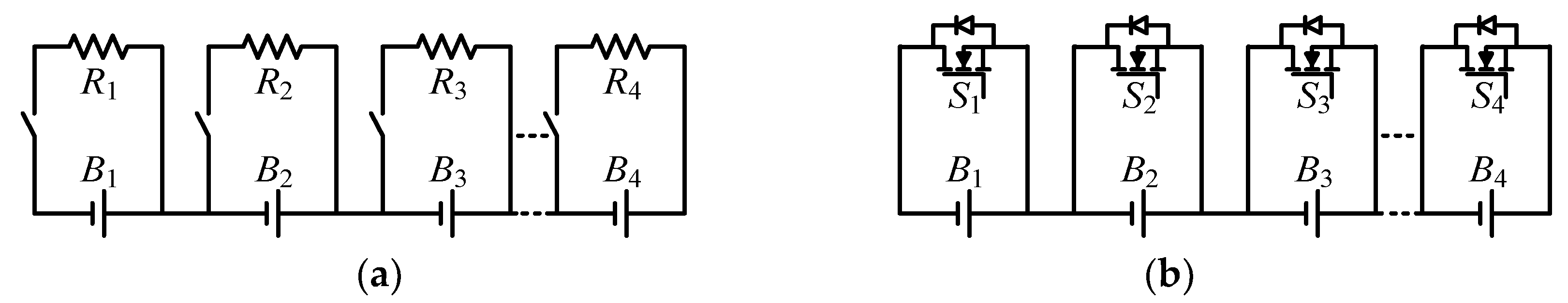
3.1.1. Dissipative Equalization Scheme

The dissipative equalization scheme refers to releasing the energy of the over-charged battery through its parallel energy-consuming elements during the operation of the battery strings, so as to reduce the battery energy to the average value level. The dissipative equalization scheme can be classified by the energy-consuming elements into two types: fixed shunt resistors scheme equalization and switched shunt resistors equalization [31], as shown in Figure 2.
Although the low efficiency and the resistors’ heating are the main drawbacks of the dissipative equalization scheme, it is still one of the most widely used schemes because of its simple design, low cost, small circuit volume and low control complexity [32].

3.1.2. Non-Dissipative Equalization Scheme

The non-dissipative equalization scheme, which exists in a symmetrical way compared with dissipative equalization scheme, refers to the transmission of battery energy within a pack through various energy-storage elements, so as to efficiently realize energy balancing [33]. It is not necessary to waste higher-voltage battery energy, which allows for higher equalization efficiency and faster equalization speed. According to the method of driving energy transmission, the non-dissipative equalization scheme can be divided into three types: voltage-difference-based type, current-direction-based type and hybrid type.

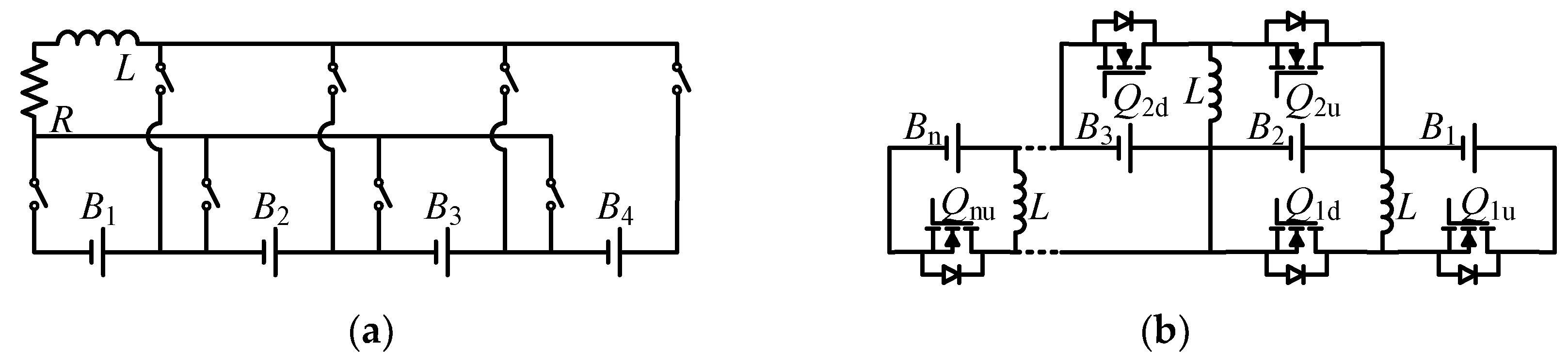
Voltage-Difference-Based Type

The voltage-difference-based type refers to driving energy transmission from the battery with high voltage (i.e., high power) to the battery with low voltage (i.e., low power) by means of the voltage difference, which can be realized by capacitors, transformers, etc.
Taking the classic switched-capacitor balancing circuit [34,35], as shown in Figure 3, as an example, we illustrate the balancing process. Firstly, the over-charged and over-discharged batteries are identified through the voltage sensors, followed by discharging the over-charged battery to the capacitor until the voltages reach to a consistent value. Secondly, the energy of the charged capacitor is transferred to the over-discharged battery. In this scheme, the functions of capacitors are storing energy, balancing the voltage difference between batteries and transferring energy with a voltage difference.
Based on the above topology, a series–parallel structure of switched capacitors is proposed in [36], which improves the equalization speed but necessitates the use of more switches. In [37,38,39,40,41,42,43], the capacitors’ connection structure is optimized to achieve a good tradeoff between system complexity and equalization performance. A resonant switching capacitor equalization topology is proposed in [44], which can realize soft switching while balancing the battery energy. In addition, the forward-mode transformer can also be used in the voltage-difference-based type equalization scheme, but the magnetic circuit saturation needs to be considered [45,46].
Since this scheme uses the voltage difference between batteries to drive energy transmitting, the equalization speed is slow under a small voltage difference (i.e., the battery energy difference is not obvious).

Current-Direction-Based Type
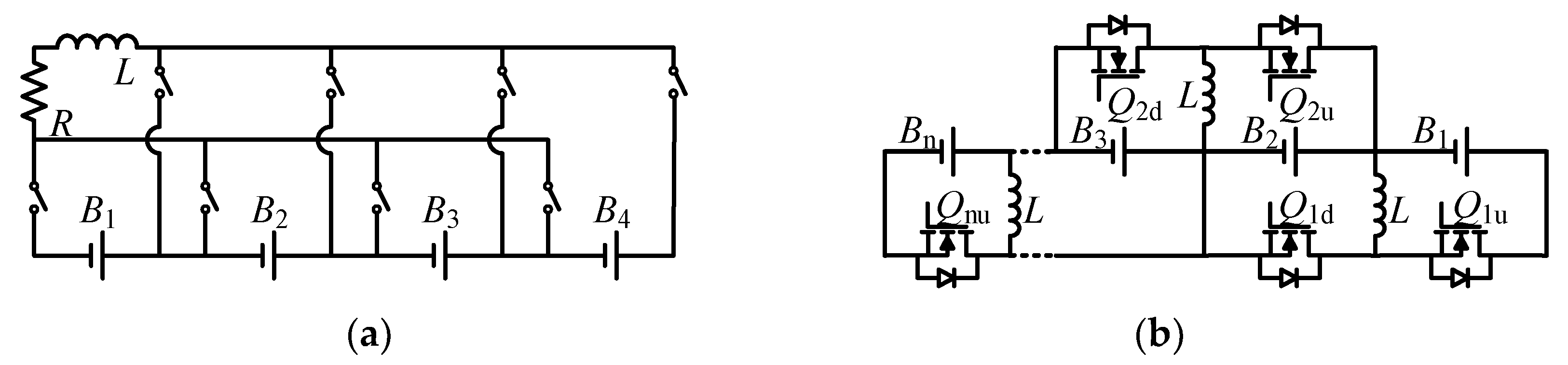
The current-direction-based type, which exists in a symmetrical way compared with the voltage-difference-based type, refers to using inductive elements to inhibit the current direction change and drive energy to flow with the current direction instead of the voltage difference. By adjusting the circuit, the current can be controlled to flow out of the over-charged battery; then, the energy is stored in the inductive element and further flows into the over-discharged battery. The inductive element is normally a inductor or transformer.
Taking the classic switched-inductor balancing circuit [47], as shown in Figure 4a, as an example, we illustrate the balancing process. Firstly, the over-charged and over-discharged batteries are identified through the voltage sensors, followed by discharging the overcharged battery to the inductor. Secondly, the energy of the charged inductor is transferred to the over-discharged battery by using the inductor freewheeling function. In this scheme, the functions of inductors are storing energy, maintaining the current direction and transferring energy with current direction.
Based on the above topology, a multiple switched-inductor topology is proposed in [48], which can reduce the number of switches. However, the energy transmit path becomes longer, limiting the equalization speed. Similarly, some DC/DC converters, as shown in Figure 4b, can also be employed in the current-direction-based type scheme [49,50]. Compared with the basic switched inductor equalization scheme, this scheme has the advantage of higher integration, and disadvantages of more complex design and higher cost. Similarly, the flyback mode transformer can also be used in this scheme.
Since the energy-transmitting process of the current-direction-based type is completely unrelated to the voltage difference, the energy can be transferred quickly even with extremely small voltage differences in batteries.

Hybrid Type

For the purpose of facilitating modular control and improving the equalization rate, numerous papers have aimed to design a control strategy that can combine the above two types of equalization strategies and obtain satisfactory results.
A typical topology of hybrid type, which combines the forward and flyback structure, is shown in Figure 5a. In this topology, two windings on the n1 side form a forward structure, and the n2 winding and the n1 windings form two flyback structures. The number of turns of each winding on the n1 side is equal. The driving signals of each switch are the pulse signals with the same phase. When each switch is turned on, the high-voltage batteries transfer energy to the low-voltage batteries (voltage difference), while the n2-side winding stores the transferred energy. When each switch is turned off, the diode on the n2 side is turned on. The energy stored in the n2-side winding is released to each battery through the diode (current direction), and the transformer magnetic core on the n1 side is reset at the same time. This method combines the forward and flyback transformers, which not only solves the problem of the transformer magnetic core reset in the forward mode, but also can balance the battery pack without using sensors. The above method is further extended in [51] to a two-module structure, as shown in Figure 5b. For the submodule, each winding transfers energy through a forward mode transformer. Between the two submodules, the energy is transferred through a flyback mode transformer, while assisting in magnetic core reset. The energy transfer direction between two submodules is determined by the duty ratio of the two submodules.
Based on [51], an equalization method that does not require an additional magnetic core reset circuit is proposed in [46], which is achieved by setting two submodules with different winding directions. The authors in [52] reported an optimized automatic equalizer based on coupled half-bridge converters which use a multi-winding transformer. The number of windings and the volume of the converter can be reduced. In [53], a new bidirectional cell-to-cell active equalization method using a multi-winding transformer has been proposed. Although this method increases the volume of the converter and requires sensors, it achieves direct and rapid energy transfer between battery cells. In addition, other hybrid equalization strategies, such as the combination of capacitors and DC/DC converters [54] and the combination of different DC/DC converters [55], are proposed and investigated. These methods are more flexible. We can choose and design an appropriate balancing strategy according to the actual condition.

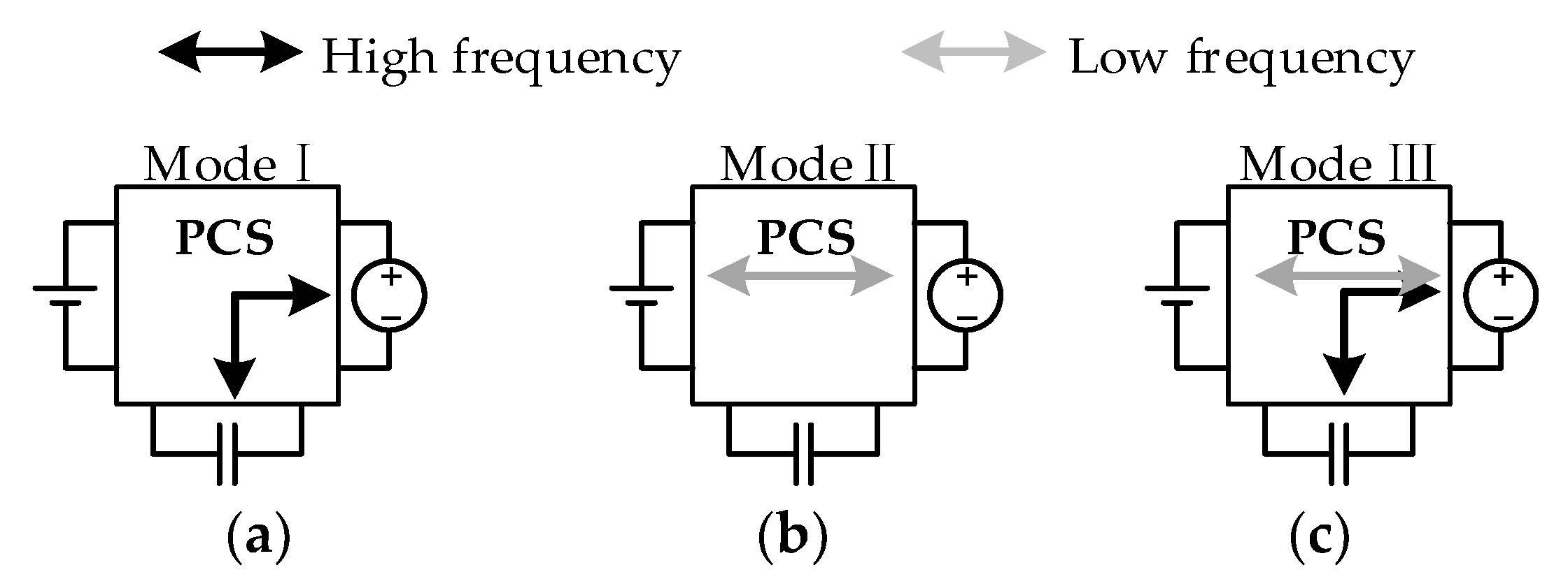
3.2. Multi-Port Power Conversion System in BS-HESS

The multi-port converter, which integrates different energy ports on the same converter, is an important piece of equipment needed to serve the BS-HESS. The multi-port converter is responsible for controlling the power exchange among various energy-storage devices, the load and the DC bus. Compared with a structure composed of two or more independent traditional DC/DC converters, the multi-port converter can provide a flexible energy-flowing path among different ports, with lower cost, lower communication requirements, higher efficiency and higher power density. The multi-port converters can be divided into three types: non-isolated multi-port converter, partially isolated multi-port converter and fully isolated multi-port converter.
Previously, multi-port converters were often applied to renewable-energy power-generation systems. Generally, these include renewable-energy ports, energy-storage ports, and DC bus ports. The multi-port converter proposed in [56] contains three operating modes, in which the power of the energy-storage port and the DC bus port can flow in both directions, and the renewable energy port can only output power. Considering the characteristics of the terminal ports in the BS-HESS, the multi-port converter contains the following three operating modes: (1) supercapacitors respond to high-frequency components of DC bus power fluctuations, as shown in Figure 6a; (2) lithium-ion batteries respond to low-frequency components of DC bus power fluctuations, as shown in Figure 6b; (3) supercapacitors and lithium-ion batteries respond to high- and low-frequency components of DC bus power fluctuations, respectively and simultaneously, as shown in Figure 6c.
The multi-port converter must realize the function of bidirectional power flowing if the converter could be successfully applied to the BS-HESS, because the multiple terminal ports connect with the supercapacitors, lithium-ion batteries and DC bus. This property is the main difference from the multi-port converters applying to renewable energy-generation systems.

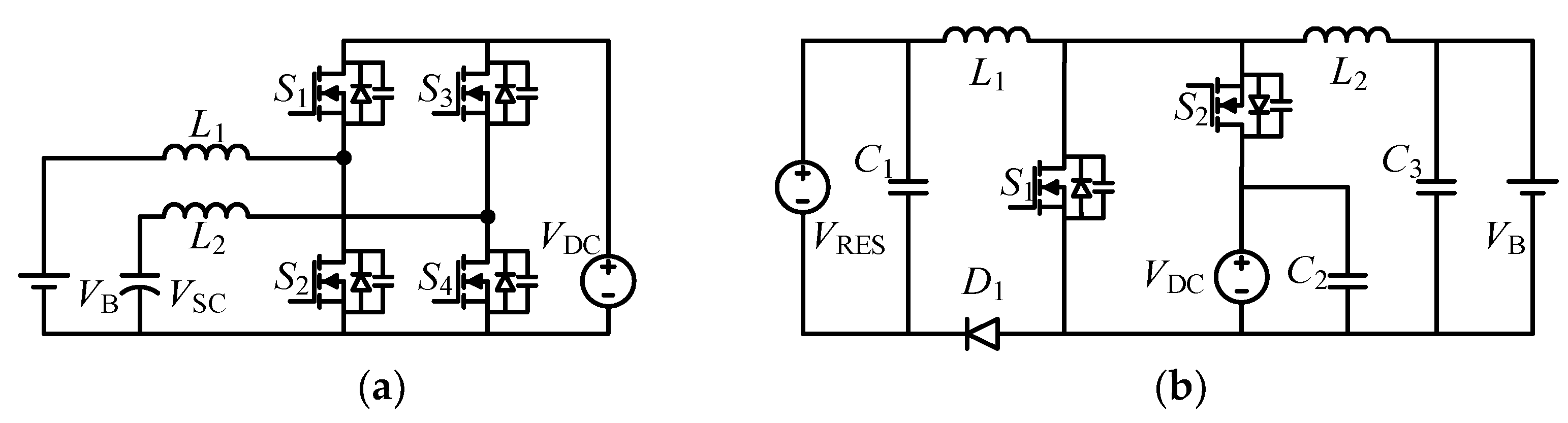
3.2.1. Non-Isolated Multi-Port Converter

Most non-isolated multi-port converters are derived from traditional DC/DC converters. In [57], a method is proposed to generate a three-port converter (TPC) by reconstructing the power flowing path of dual-input converters or dual-output converters, and the general principles of generating and optimizing the three-port converter topology are summarized. One specific example in [57], namely, Boost-TPC, is shown in Figure 7a. The performance of the circuit is verified. The three ports share the same inductor to achieve transferring energy by applying a time-multiplexing control strategy. Since only one inductor is used in Boost-TPC, the efficiency and the power density can be improved. However, only the energy-storage port can achieve bidirectional power flowing. Thus, the application of Boost-TPC in the BS-HESS is limited.
In [58], the authors added a soft switching cell and achieved a bidirectional power-flowing path from the output port to the energy-storage port on Boost-TPC, as shown in Figure 7b. The power of the two ports can flow in both directions, and the soft switching function in all operating modes is realized. The topology efficiency is improved. However, the bidirectional power flow among all ports still cannot be realized, and the switch numbers and the system cost are increased and the control is more complex. These two types of converters mentioned above belong to integrated multi-port converters.
In [59,60], the authors studied the parameter design and the control algorithm of a multi-port converter composed of several half bridges. The converter shown in Figure 8a, is composed of several discrete topologies, and all ports can realize bidirectional power flowing. Its disadvantage is the increase in the cost and volume. In order to solve this problem, a multi-port converter containing only two switches, as shown in Figure 8b, is proposed in [61]. However, only two ports can realize bidirectional power flowing.
The non-isolated multi-port converters have advantages of few components, small size and high efficiency, with one obvious disadvantage of being electrically non-isolated from port-to-port. The non-isolated multi-port converter is suitable for the lower-voltage BS-HESS, such as a BS-HESS in the renewable-energy power-generation system and electric vehicle systems.

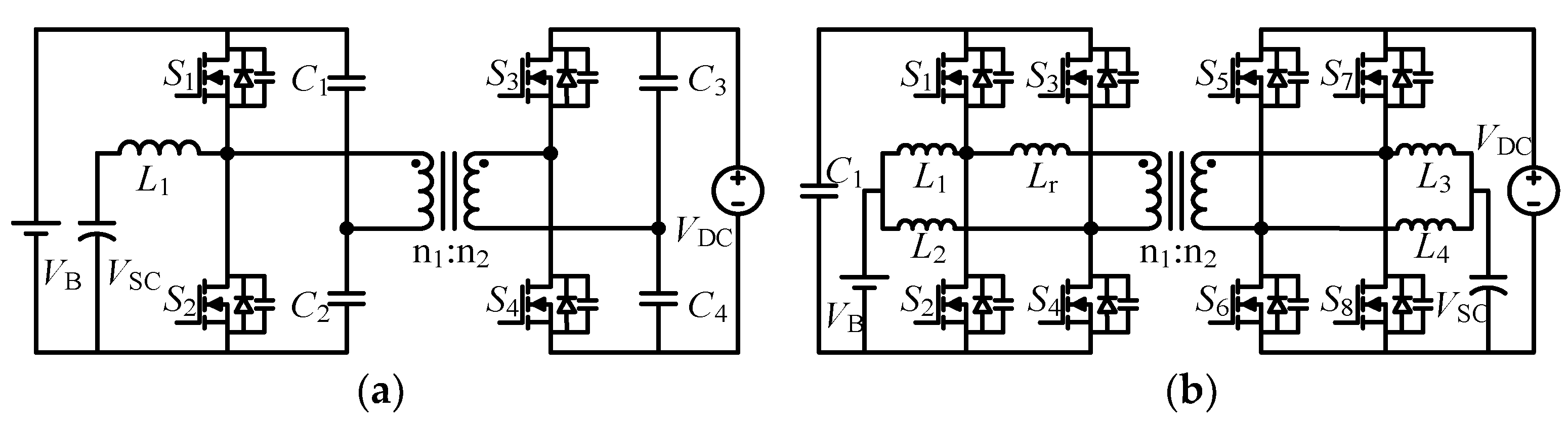
3.2.2. Partially Isolated Multi-Port Converter

A half-bridge, partially isolated, multi-port converter for electric vehicle BS-HESS has been proposed in [62], as shown in Figure 9a. Additionally, a full-bridge, partially isolated, multi-port converter for the BS-HESS has been proposed in [63], as shown in Figure 9b. Because the two topologies in [62,63] have one dual-winding transformer, only some ports can be electrically isolated from each other. Therefore, this kind of topology is called partially isolated multi-port converters. The two topologies shown in Figure 9 can achieve bidirectional power flowing among all ports, and soft switching can be realized. For the half-bridge topology, the number of switches is smaller and the cost is lower. However, the use of high-capacity capacitors could increase the volume of the converter. The full-bridge topology is small in size and high in reliability. However, the use of more switches could increase the cost.
For the partially isolated multi-port converter, the ports with same voltage level are non-isolated. Meanwhile, the ports with different voltage levels are electrically isolated, or the port connecting with the equipment that needs to be isolated should be electrically isolated from other ports by the transformer. Compared with the non-isolated multi-port converter, the safety of partially isolated multi-port converter is improved.

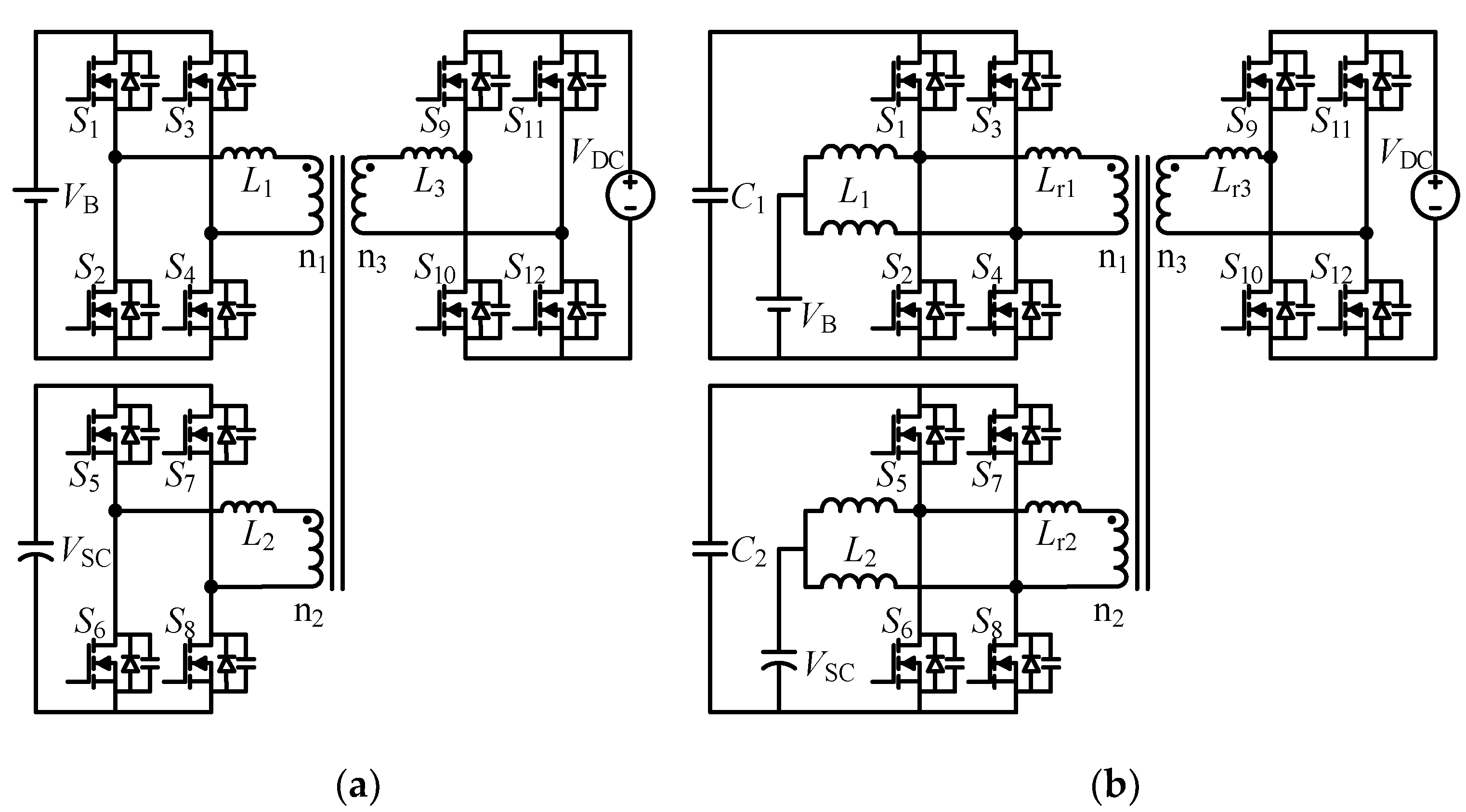
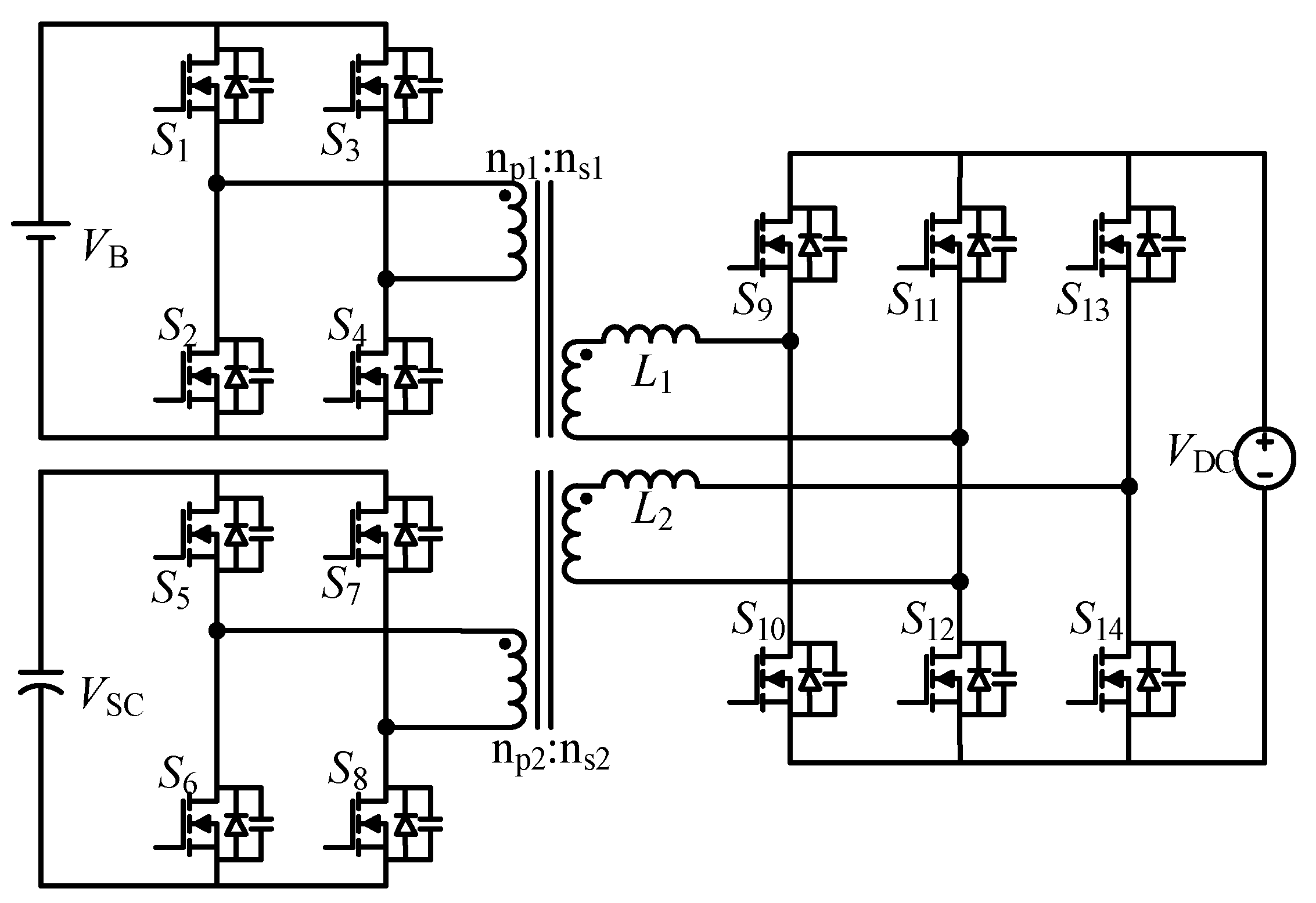
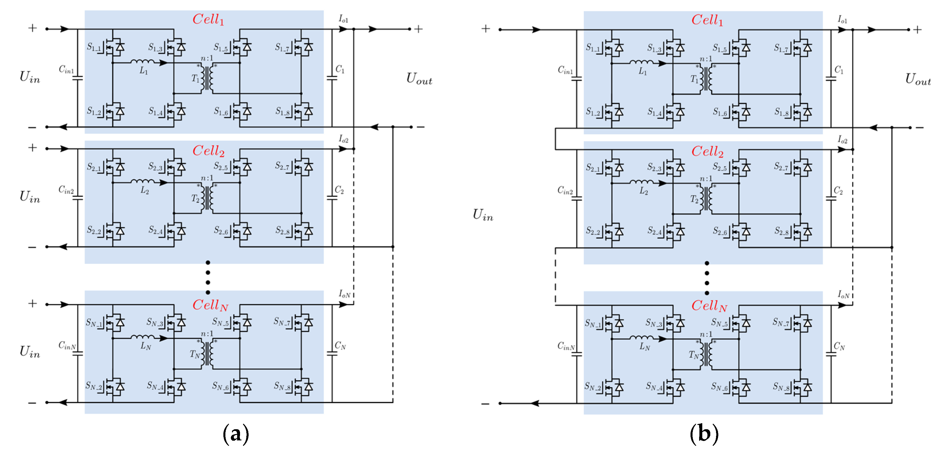
3.2.3. Fully Isolated Multi-Port Converter

The fully isolated multi-port converter employs a multi-winding transformer or several dual-winding transformers to isolate all ports from each other. All ports can realize bidirectional power flowing, with a wide range of applicable voltages. Although the cost of the full-bridge structure is higher, it is often used to construct the fully isolated multi-port converter because it is easy to implement soft switching. A triple-active-bridge (TAB) converter composed of three full-bridge cells and an isolation transformer, which is shown in Figure 10a, has been proposed in [64] with the corresponding decoupling control strategy. The authors propose another TAB converter in [65], namely, a current-fed triple-active-bridge (CF-TAB) converter, as shown in Figure 10b. Compared with the voltage-fed triple-active-bridge (VF-TAB) converter, the CF-TAB converter can be controlled by a duty cycle, with the properties of wider voltage range, wider soft switching range and lower current ripple. Therefore, the CF-TAB converter is more suitable for BE-HESS than the VF-TAB converter.
A dual-transformer-based, asymmetric triple-port active bridge converter (DT-ATAB) has been proposed in [66], as shown in Figure 11. Compared with the TAB converters in [64,65], the DT-ATAB converter can reduce the circulating power between different ports and can reduce the design complexity of the transformer. The magnetic short-circuit conditions are mitigated. However, the two transformers lead to an increase in the size of the converter, in the number of switches, and in the cost of the converter.
For the fully isolated multi-port converter, all ports are electrically isolated from each other. The port voltage range is wider and the safety is higher. It is suitable for a high-power BS-HESS, such as the grid energy-storage system.

3.2.4. Conclusions of Multi-Port Converters in BS-HESS

In the BS-HESS, the voltage range of the supercapacitors is wider. Therefore, the partially isolated multi-port converter and the fully isolated multi-port converter are more suitable for the BS-HESS. Partially isolated multi-port converters have few components, resulting in a smaller size and lower cost. However, we must be aware of the security of non-isolated ports. The fully isolated multi-port converters have been used in numerous applications due to the property of higher safety. However, the design of the multi-winding transformer is more complex, and the volume is larger and the cost is higher. In the future, attention should be paid to the optimization of the multi-port converters in terms of the control complexity, decoupling strategy, safety, cost, efficiency and topology.

3.3. Energy Management System in BS-HESS

EMS is the brain of the BS-HESS, which mainly realizes the safe and optimal dispatch of energy. By coordinating the energy distribution between different energy-storage devices, a reasonable EMS can effectively reduce the loss of the BS-HESS and improve the technical and economic performance. At the same time, the EMS enables the energy-storage devices to work within a safe and reasonable range. For the BS-HESS, a reasonable energy management strategy can maximize the characteristics and advantages of various types of energy-storage devices, and legitimately provide energy and power to the load. Thus, the total performance (efficiency, cost, etc.) of the system can be improved [67].
Based on the current literature, the energy management strategies can be divided into two categories: the rule-based energy management strategy and the optimization-based energy management strategy [67,68]. The specific control methods are shown in Figure 12. The rule-based energy management strategy is to set rules in advance based on experience, so as to manage the output power of various energy-storage devices. The optimization-based energy management strategy is to minimize the cost function according to the optimization objective, and to adjust the power distribution according to the operation value.

3.3.1. Rule-Based Energy Management Strategy

We take the fuzzy control to explain the rule-based energy management strategy. In the BS-HESS, the EMS based on the fuzzy control does not depend on the precise mathematical model. Thus, the robustness performance is good. The input is fuzzified through a user-defined membership function (usually a trapezoid or a triangle), then the output is calculated and inferred by pre-set fuzzy rules. Finally, the output is defuzzified to obtain the real result [69]. A block diagram of the fuzzy control principle is shown in Figure 13. Generally, the input variables of the fuzzy controller can be set as the load demand power and state of charge of each energy-storage device, and the output variables are the percentages of the discharge power of each energy-storage device to the demand power. However, the establishment of the fuzzy controller mainly relies on experience, resulting in difficulty obtaining the global optimal control results.
Some other rule-based control methods, such as threshold control [70] and the filter method [71], have the advantages of simplicity, effectiveness, strong robustness and being easy to implement, but with the disadvantage of poor adaptive correction performance.

3.3.2. Optimization-Based Energy Management Strategy

We take MPC to explain the optimization-based energy management strategy. In the BS-HESS, the EMS based on MPC can control the target in real time through quantitative calculation, with good control effect and strong robustness [72,73]. The application of MPC includes model building, rolling optimization and feedback correction. The optimization objective for energy management of the BS-HESS can be the total measured current itotal, the measured battery current ibatt, the measured supercapacitor current icap, the measured battery voltage vbatt and the measured supercapacitor voltage vcap. The optimization objective can also be the optimization of the total energy loss of the BS-HESS within the prediction interval. Furthermore, some constraints are required for avoiding the batteries or supercapacitor being over-charged and over-discharged. The outputs of the MPC are the power partition coefficients for managing the battery and the supercapacitor, respectively. A block diagram of MPC principle is shown in Figure 14. The problem of the EMS based on MPC is its high dependence on model accuracy.
Some other optimization-based methods, such as dynamic programming [74], can realize the global optimization. However, the DP-based EMS cannot be implemented online due to its heavy calculation burden. In addition, a simple neural-network-based algorithm is proposed in [75]. It can realize the online optimization of power allocation, but it needs to rely on a large amount of training data and lacks parameter robustness. Therefore, the different strategies have different characteristics, and can be subject to different applications.

3.3.3. Research Prospect

Although the theoretical basis and experimental verification on the BS-HESS have been greatly developed, the requirements for EMS are more complex due to the fine management and the increase in functionality. Therefore, the comprehensive application of the BS-HESS still faces huge challenges. The following prospects are made for the future of the BS-HESS:
(1)
The rapid development of artificial intelligence has brought opportunities for energy management strategies of the BS-HESS. The optimization results obtained by big data can be learned through artificial intelligence algorithms, which can further improve the reliability of power distribution for the BS-HESS. Research on artificially intelligent power-distribution strategies is an important direction.
(2)
Currently, different power-distribution strategies for the BS-HESS are developed with a variety of characteristics. Integrating different power-distribution strategies can promote strengths and avoid weaknesses, which will be a promising research direction.
(3)
Numerous energy management strategies of the BS-HESS are highly dependent on the accuracy of parameters. Inaccurate parameters could result in a poor control effect. Improving the parameter robustness is the only way to realize the wide application of the BS-HESS.

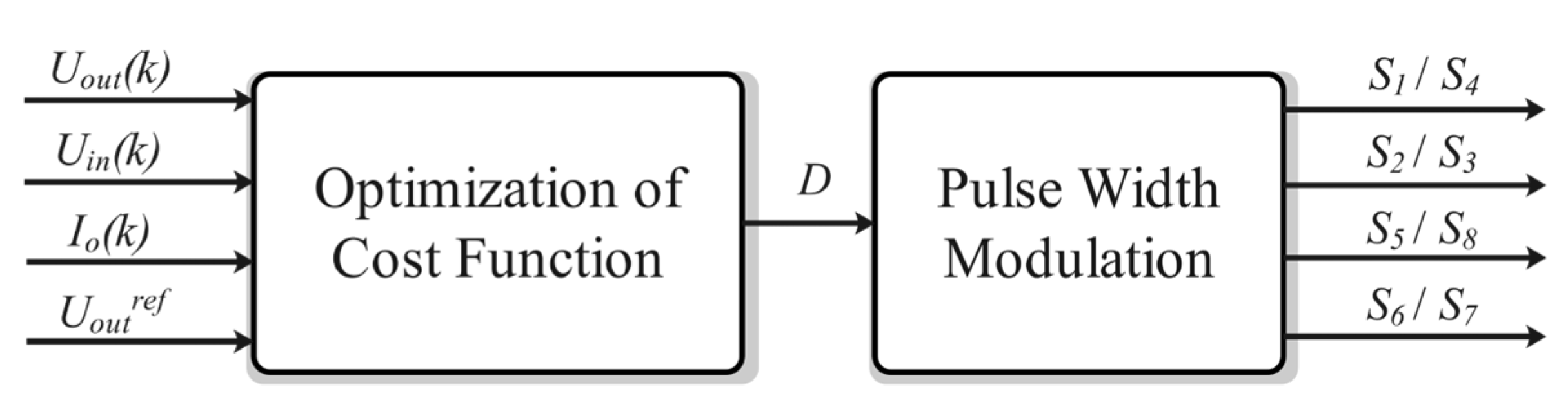
3.4. Model Predictive Control Applied in Bidirectional Converters for BS-HESS

With the development of the BS-HESS, various power converters have been widely used, which puts forward higher requirements for the control technology. Some of the control schemes are shown in Figure 15. As an advanced control scheme, MPC presents several advantages: intuitive concept, excellent dynamic performance, ease of multi-objective optimization, and ease of multivariable consideration [76]. Therefore, MPC has been widely applied as the control strategy for energy-storage converters in recent years.
In this paper, we mainly focus on the DAB converter, as shown in Figure 16, which is a typical converter and widely used in the BS-HESS. The development process and application status of MPC in DAB converters are introduced. On this basis, the development direction of predictive control applied to the DAB converter is discussed.

3.4.1. Finite Control Set MPC

Patricio et al. [76] divided MPC strategies into two categories, namely, continuous control set (CCS)-MPC and finite control set (FCS)-MPC. For the former strategy, the switching frequency is fixed and the modulator is indispensable to control the system. For the latter strategy, the control signal of the switches can be received from the controller directly, so the modulator is not necessary and the switching frequency is variable.
An FCS-MPC scheme was proposed in [77] for DAB converters. Instead of using phase-shifting modulation, the DAB converter is regarded as consisting of a full bridge inverter and a full bridge rectifier. The switches in each full bridge are controlled separately. The control block diagram is shown in Figure 17.
Based on this method, the prediction expressions are derived, which refer to the output current of the inverter and the output voltage of the rectifier, respectively:
I L ( k + 1 ) = I L ( k ) + T s L { S b r i d g e 1 U i n n U 2 }
U o u t ( k + 1 ) = U o u t ( k ) + T s C 2 { S b r i d g e 2 I L I o }
The current and voltage in Equations (1) and (2) are set as control targets. Then, the cost function can be established as:
J 1 = | I L r e f I L ( k + 1 ) |
J 2 = | U o u t r e f U o u t ( k + 1 ) |
However, this method does not use phase-shifting modulation, so the working frequency of the transformer is far lower than the switching frequency, leading to large volume and low power density. In addition, soft switching is hard to achieve.

3.4.2. Continuous Control Set MPC

Song et al. [78] proposed a CCS-MPC scheme based on the single phase shift (SPS) modulation for DAB converters. In this method, the phase difference D between the switch signals on the two sides is used to control the output voltage. The prediction expression of the output voltage is derived based on SPS modulation in this paper:
U o u t ( k + 1 ) = U o u t ( k ) + n ( D 2 + D ) 2 f s 2 L C U i n ( k ) I o ( k ) f s C
The cost function is as follows:
J = [ U o u t r e f U o u t ( k + 1 ) ] 2
The control block diagram is shown in Figure 18. Based on phase-shifting modulation, this method can realize zero voltage switching (ZVS), and the transformer frequency is consistent with the switching frequency. In addition, it shows excellent dynamic performance when the input voltage or the load suddenly changes.
A current stress-optimized (CSO) scheme with model-based feedforward for DAB converters was proposed in [79]. In essence, this scheme also used the idea of CCS-MPC and expanded it to the extended phase shift (EPS) modulation. Similarly to in [78], this paper takes the output reference voltage tracking as the objective, and derives the prediction expression of output voltage under EPS as follows:
U o u t ( k + 1 ) = U o u t ( k ) + D 2 2 + D 2 D 1 2 2 f s 2 L C n U i n ( k ) I o ( k ) f s C , ( 0 D 1 D 2 1 )
U o u t ( k + 1 ) = U o u t ( k ) + 2 D 2 2 D 1 D 2 D 2 2 2 f s 2 L C n U i n ( k ) I o ( k ) f s C , ( 0 D 2 D 1 1 )
Taking advantage of the high degree of freedom, the EPS modulation can be combined with CSO control, which can reduce the inductor current stress while retaining the excellent dynamic performance of MPC. The control block diagram is shown in Figure 19.
In [80], a turn-off switching loss-optimization strategy with CCS-MPC is proposed for a DAB converter. Similarly to in [79], this strategy is also based on EPS modulation, which can not only significantly reduce the turn-off loss, but also reduce the current stress. Additionally, the efficiency improvement is particularly obvious under high-frequency working conditions.
Han et al. [81] analyzed the state-space averaging model-based discretization and prediction technique in the CCS-MPC scheme, and proved the inevitability of the existence of the steady-state voltage bias in [78]. To eliminate this bias, a new steady-state bias-elimination method was proposed by modifying the reference value of the target output voltage.
The CCS-MPC scheme was extended from a single DAB module to multiple DAB modules in [82,83], and the power sharing of each submodule was successfully realized. The input-isolation output-parallel (IIOP) connection topology, as shown in Figure 20a, is investigated in [82], adopting the EPS modulation to optimize the current stress. The input-series output-parallel (ISOP) connection topology, as shown in Figure 20b, is investigated in [83], adopting the SPS modulation.
The above CCS-MPC schemes show excellent dynamic performance, and can also be extended to multiple phase-shift modulation while maintaining the advantages of fixed switching frequency and ZVS in phase-shifting control. The way to obtain the control quantity is by minimizing the cost function to obtain the explicit expression of control quantity. In this way, the given objective can be controlled successfully and accurately. However, the amount of offline calculation (i.e., the acquisition of explicit expression) is related to the phase-shifting control mode and the number of submodules. In addition, considering multiple objectives in the cost function, the explicit expression of the control quantity will be difficult or even impossible to obtain, limiting the use of CCS-MPC schemes in multi-objective optimization.

3.4.3. Moving Discretized Control Set MPC

In order to solve the problems of the CCS-MPC scheme, Chen et al. [84] proposed a moving discretized control set (MDCS)-MPC scheme based on the SPS modulation for DAB converters. Different from the continuous set control quantity D of the CCS-MPC in [78], the control quantity D in [84] is discretized in its value range. The control quantity updating process is as follows. Firstly, a limited number of Di’ near the control quantity D obtained from the previous working cycle are selected. Secondly, the selected Di’ are substituted into the cost function J successively, and the Di’ which can minimize J will be selected as the update values of the control quantity. Third, the above steps are repeated until the object converges to the target value. In this way, the scheme solves the difficulty of obtaining the explicit expression of the control quantity in CCS-MPC.
In addition, the adaptive step and two-step MPC were used to search for the optimal control quantity in [84], with the steady-state error-compensation loop being introduced. These brought a higher accuracy and speed to the scheme. The cost function is as follows:
J = α 1 G 1 + α 2 G 2
where:
{ G 1 = [ U o u t r e f U o u t ( k + 2 ) ] 2 G 2 = [ U o u t ( k + 2 ) U o u t ( k ) ] 2
The first term G1 reflects the difference between the predicted value and the reference value of the output voltage, which is responsible for achieving the regulation of the output voltage U out to the reference value Uoutref, whereas the second term G2 reflects the difference between the predicted value and the real-time value of the output voltage, which is responsible for reducing the sample noise disturbance and mitigating the oscillation when the load is rapidly changing.
It can be seen that since the explicit expression of the control quantity is unnecessary in this method, multiple objectives can be selected into the cost function. In addition, since this method is essentially continuous set model predictive control, it retains the advantages of CCS-MPC scheme.
Based on [84], the MDCS-MPC scheme was expanded to the EPS modulation in [85], with the CSO being integrated, similarly to the scheme in [79]. The cost function is as follows:
J = α 1 G 1 + α 2 G 2 + α 3 G 3
where G1 and G2 are the same as those in (9) and G3 reflects the peak value of the inductor current, responding to reduce the inductor current to the minimum value under the real-time working condition. Using the same method as that presented in [84], the control quantities in [85] can be obtained.
In [86], the MDCS-MPC scheme was expanded to the triple phase shift (TPS) modulation, and shows us the feasibility and flexibility of multi-objective optimization under TPS modulation. In [87], the MDCS-MPC scheme was applied to stabilizing DC microgrids with DAB converters. Two objectives (load current and DC bus voltage) are introduced into the cost function, and experimental results show significantly better performance than PI control. In [88], the large signal stability of the MDCS-MPC scheme was analyzed in detail. The element that takes charge of the large signal stability of DAB converters was added to the cost function, leading to satisfactory results.
In the typical applications of the BS-HESS, such as in rail transit systems, electric vehicles and grid energy-storage systems, large fluctuations can emerge inevitably due to the starting and braking of the electric vehicle or the rapid change of load or source, etc. Then, the system needs to respond to these transient processes timely to meet specific needs. In addition, two energy-storage devices in the BS-HESS also require PCS to achieve multiple targets simultaneously. Based to the above analysis, the MPC scheme is extremely suitable for controlling PCS due to its excellent dynamic performance and multi-objective control ability. Therefore, the MPC scheme is a key topic in the BS-HESS, and is worthy of further research.

4. Applications of BS-HESS with Economic Feasibility Analysis

The BS-HESS is widely considered as a promising solution for energy and power management, which has a broad market prospect. In this section, several typical application scenarios of the BS-HESS with economic feasibility analysis will be introduced [89].

4.1. Applications of BS-HESS

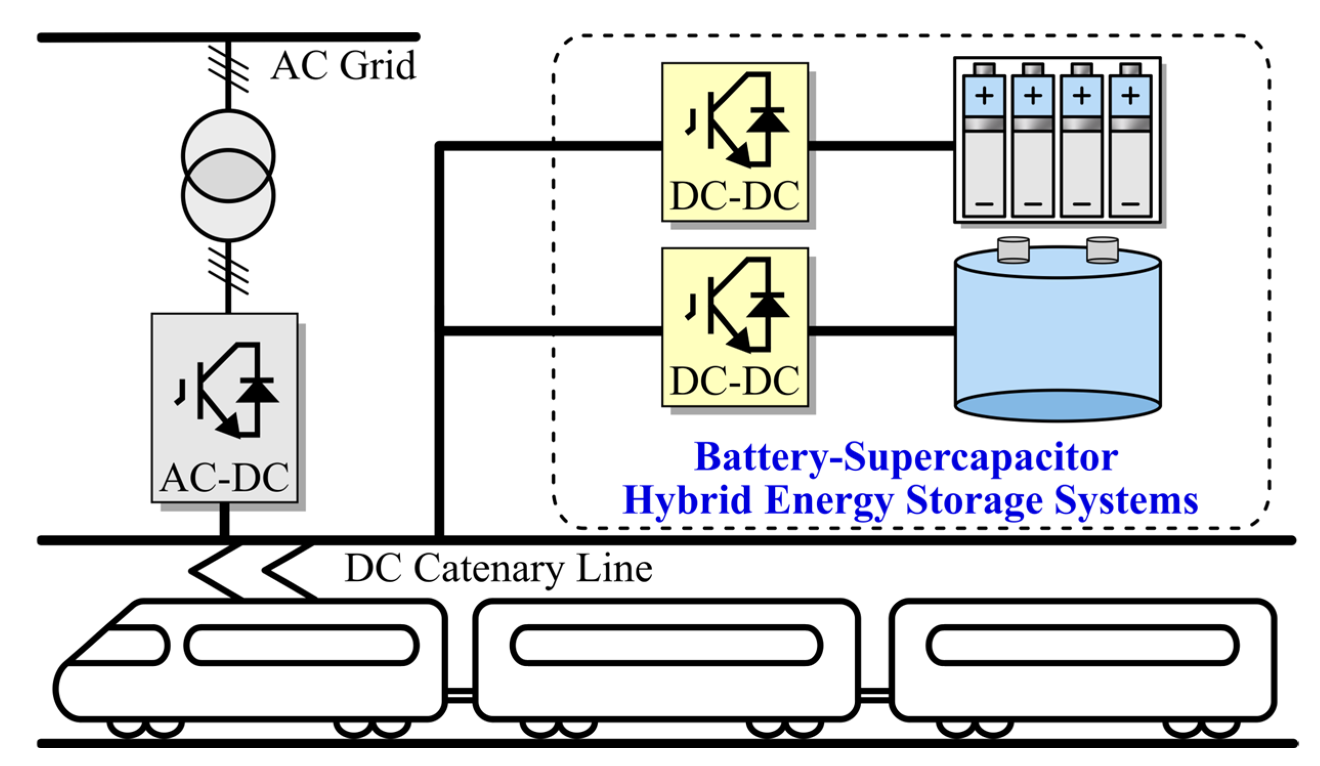
4.1.1. Urban Rail Transit System

In urban rail transit applications, the regenerative braking energy of the train is considerable, and accounts for 21–39% of the total energy consumption during the traction [90]. Therefore, energy-storage systems have been widely investigated in rail transit systems, aiming to recycle the considerable regenerative energy [91].
Generally, energy-storage systems can be divided into ground and on-board type systems according to installation location. Compared to the on-board type, the ground type shows lower investment and maintenance costs, and has emerged as an attractive solution for the urban rail transit systems [92]. A typical case of a ground-type BS-HESS in urban rail transit systems is shown in Figure 21.
Compared to conventional battery energy-storage systems, the BS-HESS has better dynamic performance, allowing it to adapt to megawatt-class power fluctuations at short notice. In addition, the BS-HESS has such advantages such as good cryogenic property and long service life, which are also necessary for rail transit [93]. In addition, it can also be used as a backup power source for the train to deal with power supply failures.
All the above advantages lead to the popularity of the BS-HESS in urban rail transit systems around the world. SITRAS-HES ground-type HESS equipment designed by Siemens are installed in Portugal. This technology is quite mature and has been put into use in urban rail systems in many countries. Beijing Jiaotong University designed the world’s first megawatt-class ground rail transit BS-HESS, which has been applied at Liyuan Station of Beijing Batong Line. It can recycle the regenerative braking energy of the train, saving the output energy of urban rail substation by 10–15% [94].

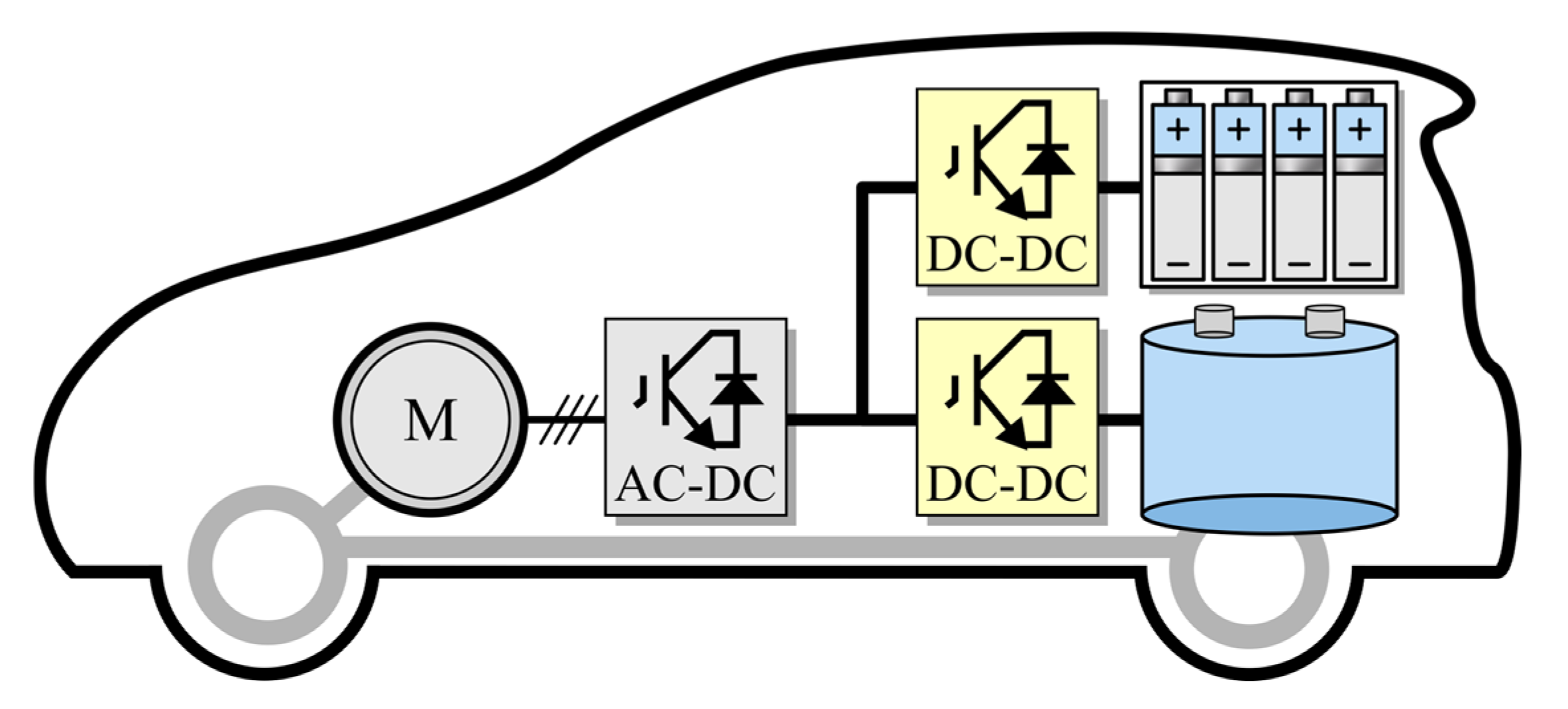
4.1.2. Electric Vehicles

In recent years, the development of electric vehicles has become a mainstream topic because of global climate change and local environmental pollution. However, the life cycle and the power density of batteries are limited [95]. Furthermore, the battery is easily broken when the vehicle accelerates suddenly, which occurs often in life [96].
The supercapacitor offers characteristics such as high power density, long life cycle, and low temperature resistance, while its energy density is relatively low. Thus, the use of the BS-HESS not only prolongs the battery lifetime but improves vehicle acceleration performance due to the combination of the advantages of batteries and supercapacitors [97]. The BS-HESS can also improve the efficiency of electric vehicles by absorbing the energy generated during braking [75]. A typical case of a BS-HESS in an electric vehicle field is shown in Figure 22.
Over the past decade, many efforts have been devoted to the use of hybrid energy storage in electric vehicles. Aspark launched the mass production version of Owl, a pure electric supercar, in 2019. It sets a new world record of breaking 100 km/h acceleration in 1.89 s, due to the motor’s better discharging efficiency through the combination of batteries and supercapacitors. Faw started application research on supercapacitors in vehicles in 2010. After 10 years of efforts, the Hong Qi H5 pure electric version was invented, which uses supercapacitors to enhance the star-up and shut-down performance of the electric vehicle under low-temperature conditions, showing good dynamic performance.

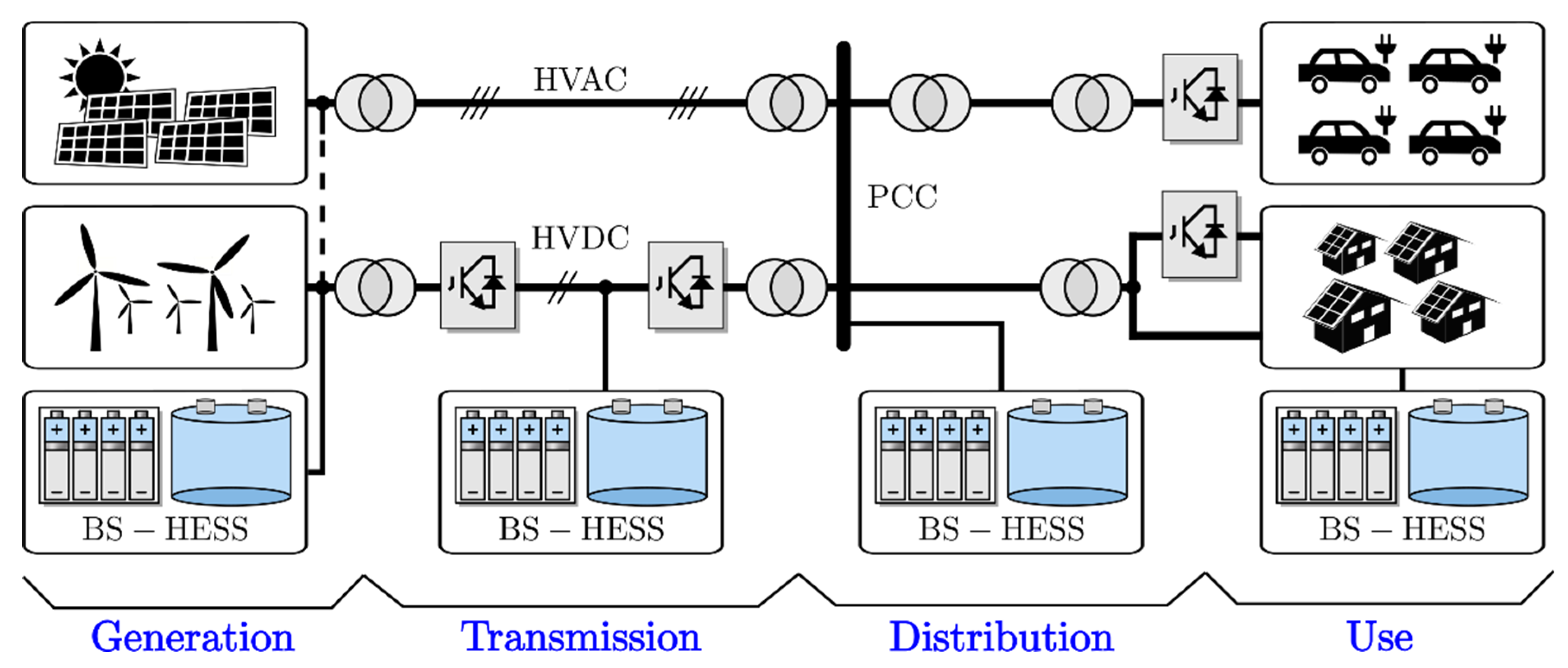
4.1.3. Grid Energy Storage

Nowadays, renewable energy, especially photovoltaic and wind power, have become the most attractive solution to the threat of climate change [98]. However, photovoltaic and wind power can hardly supply power continuously by themselves due to their intermittent nature [99]. An effective solution that includes energy storage in the renewable-energy-generation systems framework [100] is proposed to stabilize the power supply of renewable energy. Figure 23 depicts the applications of the BS-HESS in a new power system, where the proportion of renewable energy is gradually increasing. The BS-HESS applications are embodied in the power generation, transmission, distribution, and use of the new power system, which will be described in detail below.
(1)
Generation. The BS-HESS smooths out the intermittent characteristic of the renewable energy sources, thereby improving system stability. In addition, the BS-HESS stores the surplus renewable energy and releases it during periods of peak system demand, thereby increasing the utilization rate of renewable energy.
(2)
Transmission. The BS-HESS can integrate with HVDC and provide active and reactive power support. In addition, the BS-HESS can be installed in overloaded transmission nodes. Therefore, the BS-HESS avoids capital investment by delaying or deferring the upgrade of the existing transmission infrastructure.
(3)
Distribution. One of the main functions of the BS-HESS is balancing the power supply and demand. Furthermore, grid black start can be realized by the BS-HESS.
(4)
Use. Users can profit by charging the BS-HESS when energy demand is low and selling the stored energy when the demand is high. Additionally, the BS-HESS can serve as an urgent power supply for critical equipment.
In [101], a composite capacity configuration based on the wavelet transform algorithm is proposed to buffer wind-power fluctuations. Compared with a single energy-storage device, the BS-HESS enables a smoother switching operation when meeting fluctuations. In [102], the authors have proposed an energy-management scheme for a BS-HESS fed by solar photovoltaic energy with fast acting dc-link voltage. Furthermore, the proposed method offers effective power management and maintains the current limiting function for both the battery and the supercapacitors.
At present, there are already demonstrations or commercial projects using a BS-HESS. Nishime wind farm in Japan is a typical demonstration project with a BS-HESS consisting of a 75 kW battery pack and a 60 kW supercapacitor. The BS-HESS is used to suppress wind-power fluctuations and enhance low-voltage ride through capacity. China’s Zhejiang Luxi-island microgrid project consists of wind power, a photovoltaic system and a BS-HESS. The BS-HESS is equipped with 2 MW battery packs and 500 kW supercapacitors. The microgrid can realize flexible switching between the grid-connected mode and the islanded mode.

4.2. Applications of BS-HESS

In Section 4.1, the advantages such as high energy density, the high power density, and the long life cycle of the BS-HESS were introduced. It is necessary to analyze the economic feasibility of the BS-HESS for practical purposes.
In [103], the authors analyzed how the use of supercapacitors increases the lifetime of the batteries and how it affects the economy of the system. Experimental results show that the BS-HESS is more cost-effective than batteries alone after the system runs over 900 days. The most economical configuration has been discussed in [104], which shows the BS-HESS plays an important role in reducing costs for microgrids. The results in [105] show that the BS-HESS is superior to battery-only or supercapacitor-only operation. The lifetime of the energy-storage system substantially increases when the supercapacitor is part of the storage framework. Soltani et al. applied the lithium-ion battery energy-storage system and the BS-HESS in electric vehicles and analyzed the cost comparison. The cost of the BS-HESS was about 69.4% of that of a lithium-ion battery, while the volume and weight of the BS-HESS can be reduced by 30% and 31% [106]. Table 2 shows the specifications and performance comparison of a battery energy-storage system and a BS-HESS.

5. Conclusions

Energy-storage systems have attracted much attention and are used in many applications, e.g., electric vehicles, renewable energy integration, and rail transit. In applications where high power density and high energy density are desired, it is necessary to employ a hybrid energy-storage system, which greatly improves the comprehensive performance and economic feasibility of the energy-storage system. Compared with the energy-only or power-only storage system, the battery–supercapacitor hybrid energy-storage system (BS-HESS) has advantages of long lifespan, low life-cycle cost, high reliability, adaptability to environment, wide operating temperature range, and high safety. This survey indicates the BS-HESS can reduce the high-rate charge and discharge current of lithium-ion batteries while avoiding high-energy outputs of the supercapacitor, extending the life cycle of the whole energy-storage system. Therefore, the BS-HESS will be a very promising way to store energy. The connection between symmetry and the circuit design provides a perfect perspective to study the BS-HESS. However, further breakthroughs are expected in this field in terms of (1) fast, efficient, and safe battery management systems; (2) low-cost, energy-freely-flowing, and multi-port power-conversion techniques; (3) economic and efficient energy management systems; (4) practical and high-performance control strategies.
A brief outlook for relevant fields is given in order to provide a reference for future work. (1) Currently, the control complexity and the contradiction between cost and loss are the limitations for the equalization control scheme of battery packs. In future work, the modular scheme will be a promising way to reduce the control complexity. Additionally, by combining different equalization schemes, the trade-off between efficiency and cost can be optimized. (2) For the multi-port converters, the power level still cannot fully satisfy the requirement of hybrid energy-storage systems. The multi-machine cooperative control is of great significance to multi-port converters. In addition, more attention should be paid to improving efficiency and decoupling methods of multi-port power-supply system. (3) As for EMS, the existing research is still insufficient in terms of intelligence, integration, and parameter robustness, which is an urgent issue to be solved in future work. (4) In terms of the model predictive control, the dependence on the accuracy of the dual-active-bridge converter model is the hurdle of its mass application. The model parameters may be inaccurate and can even change during the actual operation, which will lead to steady-state error. Therefore, it is necessary to devote more attention to reducing the dependence on the accuracy of the model, such as by employing online parameter identification and the Kalman filter. Additionally, the application of model predictive control in multiple dual-active-bridge converters will also be a research focus.
In policy terms, the example applications of electrochemical energy storage (especially novel electrochemical energy storage) should be further encouraged. The profit model and safe operation model of energy-storage power stations should be explored by issuing the related policies. The government should actively promote the recovery and secondary utilization of retired batteries to deal with the rapid development of electric vehicles. The BS-HESS stations can be constructed cooperatively for use in power generation, transmission, distribution, and in new power systems.

Author Contributions

Conceptualization, Z.D. and Z.Z.; methodology, Z.L.; validation, Z.D., Z.Z. and Z.L.; formal analysis, M.H. and Z.D.; investigation, X.L., J.Q., C.L., M.H., Y.Y. and J.B.; resources, Z.D.; data curation, R.W. and C.W.; writing—Z.D. and X.L.; writing—review and editing, Z.D. and Z.Z.; supervision, Z.D., Z.Z. and Z.L.; project administration, Z.D. All authors have read and agreed to the published version of the manuscript.

Funding

This research was funded by the National Natural Science Foundation of China, grant number 52007106; General Program of National Natural Science Foundation of China, grant number 51977124; Several Policies on Promoting Collaborative Innovation and Achievement Industrialization of Universities and Research Institutes (Trial), grant number 2020GXRC009; Shenzhen Fundamental Research Program, grant number JCYJ20210324132616040; and National Natural Science Foundation of China, grant number 52007107.

Data Availability Statement

Not applicable.

Acknowledgments

We are very grateful to the reviewers for their comments and to the editors for their processing and modification of this article.

Conflicts of Interest

The authors declare no conflict of interest.

References

  1. Qiao, L.; Zhang, X.; Sun, X.; Zhang, X.; Ma, Y. Advances in Battery-Supercapacitor Hybrid Energy Storage System. Energy Stor. Sci. Technol. 2022, 11, 98–106. [Google Scholar]
  2. Sun, J.; Li, M.; Zhang, Z.; Xu, T.; He, J.; Wang, H.; Li, G. Renewable energy transmission by HVDC across the continent: System challenges and opportunities. CSEE J. Power Energy Syst. 2017, 3, 353–364. [Google Scholar] [CrossRef]
  3. Chen, H.; Jin, J.; Chen, J. Catching up in new energy vehicle industry: Review of its development and policies in China. In Proceedings of the IEEE International Conference on Management of Innovation and Technology, Bangkok, Thailand, 21–24 September 2008. [Google Scholar]
  4. Li, X.; Ma, R.; Wang, L.; Wang, S.; Hui, D. Energy Management Strategy for Hybrid Energy Storage Systems with Echelon-use Power Battery. In Proceedings of the IEEE International Conference on Applied Superconductivity and Electromagnetic Devices (ASEMD), Tianjin, China, 16–18 October 2020. [Google Scholar]
  5. Obukhov, S.G.; Plotnikov, I.A.; Masolov, V.G. The effective energy storage for hybrid power systems with renewable energy sources. In Proceedings of the International Conference on Electrotechnical Complexes and Systems (ICOECS), Ufa, Russia, 21–25 October 2019. [Google Scholar]
  6. Andreev, M.K. An Overview of Supercapacitors as New Power Sources in Hybrid Energy Storage Systems for Electric Vehicles. In Proceedings of the National Conference with International Participation (ELECTRONICA), Sofia, Bulgaria, 23–24 July 2020. [Google Scholar]
  7. Zhang, H.; Dou, H.; Ren, J.; Li, J.; Zhang, H. Research on the application of superconducting magnetic energy storage in wind/photovoltaic generation system. In Proceedings of the International Conference on Power Electronics and Drive Systems (PEDS), Taipei, Taiwan, 2–5 November 2009. [Google Scholar]
  8. Li, X.; Wang, S. Energy management and operational control methods for grid battery energy storage systems. CSEE J. Power Energy Syst. 2021, 7, 1026–1040. [Google Scholar]
  9. Sun, B.; Tian, S.; He, J.; Liu, L.; Wang, Z.; Guo, J.; Xu, F.; Cheng, T.; Li, J. Review on Pumped Storage Power Station in High Proportion Renewable Energy Power System. In Proceedings of the IEEE 3rd Student Conference on Electrical Machines and Systems (SCEMS), Jinan, China, 4–6 December 2020. [Google Scholar]
  10. Srikanth, K.; Mahesh, K.M. Energy management of hybrid microgrid with hybrid energy storage system. In Proceedings of the International Conference on Renewable Energy Research and Applications (ICRERA), Palermo, Italy, 22–25 November 2015. [Google Scholar]
  11. Ning, Y.; Bo, Z.; Wei, L.; Shaohua, M. Hybrid Energy Storage Capacity Allocation Method for Active Distribution Network Considering Demand Side Response. IEEE Trans. Appl. Supercond. 2019, 29, 1–4. [Google Scholar]
  12. Dong-Jing, L.; Wang, L. Small-Signal Stability Analysis of an Autonomous Hybrid Renewable Energy Power Generation/Energy Storage System Part I: Time-Domain Simulations. IEEE Trans. Energy Convers. 2008, 23, 311–320. [Google Scholar]
  13. Zhang, Y.; Jiang, Z. Dynamic Power Sharing Strategy for Active Hybrid Energy Storage Systems. In Proceedings of the IEEE Vehicle Power and Propulsion Conference, Dearborn, MI, USA, 7–10 September 2009. [Google Scholar]
  14. Zhu, Y.; Yin, Z.; Tian, J. Microgrids Based on DC Energy Pool. In Proceedings of the IEEE Energy 2030 Conference, Atlanta, GA, USA, 17–18 November 2008. [Google Scholar]
  15. Jun, C.; Wang, P.; Lalit, G.; Xu, Y. A Two-Layer Energy Management System for Microgrids with Hybrid Energy Storage Considering Degradation Costs. IEEE Trans. Smart Grid 2018, 9, 6047–6057. [Google Scholar]
  16. Graber, G.; Galdi, V.; Calderaro, V.; Piccolo, A. Sizing and energy management of on-board hybrid energy storage systems in urban rail transit. In Proceedings of the International Conference on Electrical Systems for Aircraft, Railway, Ship Propulsion and Road Vehicles & International Transportation Electrification Conference (ESARS-ITEC), Toulouse, France, 2–4 November 2016. [Google Scholar]
  17. Kong, D.; Miyatake, M. Energy Management of Superconducting Magnetic Energy Storage Applied to Urban Rail Transit for Regenerative Energy Recovery. In Proceedings of the International Conference on Electrical Machines and Systems (ICEMS), Hamamatsu, Japan, 24–27 November 2020. [Google Scholar]
  18. Kollmeyer, P.; Wootton, M.; Reimers, J.; Stiene, T.; Chemali, E.; Wood, M.; Emadi, A. Optimal performance of a full scale li-ion battery and li-ion capacitor hybrid energy storage system for a plug-in hybrid vehicle. In Proceedings of the IEEE Energy Conversion Congress and Exposition (ECCE), Cincinnati, OH, USA, 1–5 October 2017. [Google Scholar]
  19. Zhang, Y.; Yu, Y.; Zhang, B.; Zhao, J.; Xu, W.; Zhou, Q. Overview of The Current Situation and Development of Lead-acid Battery. Chin. LABAT Man. 2021, 58, 27–31. [Google Scholar]
  20. Mamen, A.; Supatti, U. A survey of hybrid energy storage systems applied for intermittent renewable energy systems. In Proceedings of the International Conference on Electrical Engineering/Electronics, Computer, Telecommunications and In-formation Technology (ECTI-CON), Phuket, Thailand, 27–30 June 2017. [Google Scholar]
  21. Wang, L.; He, X.; Gao, J.; Li, J.; Jiang, C. Manufacturing method for cathode materials of Li-ion batteries. Energy Stor. Sci. Technol. 2018, 7, 888–896. [Google Scholar]
  22. Rong, X.; Lu, Y.; Qi, X.; Zhou, Q.; Kong, W.; Tang, K.; Chen, L.; Hu, Y. Na-ion batteries: From fundamental research to engineering exploration. Energy Stor. Sci. Technol. 2020, 9, 515–522. [Google Scholar]
  23. Inoue, M.; Tsuzuki, Y.; Iizuka, Y.; Shimada, M. Carbon Fiber Electrode for Redox Flow Battery. J. Electrochem. Soc. 2019, 134, 756. [Google Scholar] [CrossRef]
  24. Soltani, M.; Jaguemont, J.; Van Mierlo, J.; Van den Bossche, P. Determination of cycling frequency with the highest impact on lifetime of Super Capacitor. In Proceedings of the IEEE Electrical Power and Energy Conference (EPEC), Montreal, QC, Canada, 16–18 October 2019. [Google Scholar]
  25. Ronsmans, J.; Lalande, B. Combining energy with power: Lithium-Ion Capacitors. In Proceedings of the International Symposium on Power Electronics, Electrical Drives, Automation and Motion (SPEEDAM), Capri, Italy, 22–24 June 2016. [Google Scholar]
  26. Gomez, J.; Perez, B.; Suarez, P.; Alvarez, A.; Rivera, B. Theoretical and Experimental Studies of SMES Configurations for Design Optimization. IEEE Trans. Appl. Supercond. 2021, 31, 1–5. [Google Scholar] [CrossRef]
  27. Gnanavel, C.; Muruganantham, P.; Vanchinathan, K.; Johny Renoald, A. Experimental Validation and Integration of Solar PV Fed Modular Multilevel Inverter (MMI) and Flywheel Storage System. In Proceedings of the IEEE Mysore Sub Section International Conference (MysuruCon), Hassan, India, 24–25 October 2021. [Google Scholar]
  28. Mohamed, M.G.; Mansoure, T.H.; Samy, M.M.; Takashi, Y.; Mohammed, A.A.K.; Ahamad, T.; Alshehri, S.M.; Kim, J.; Matsagar, B.M.; Wu, K.C.W.; et al. Ultrastable Conjugated Microporous Polymers Containing Benzobisthiadiazole and Pyrene Building Blocks for Energy Storage Applications. Molecules 2022, 27, 2025. [Google Scholar] [CrossRef] [PubMed]
  29. Jian, C.; Nigel, S.; Ali, E. Battery balancing methods: A comprehensive review. In Proceedings of the IEEE Vehicle Power and Propulsion Conference, Harbin, China, 3–5 September 2008. [Google Scholar]
  30. Daowd, M.; Omar, N.; Van den Bossche, P.; Van Mierlo, J. A review of passive and active battery balancing based on MATLAB/Simulink. Int. Rev. Electr. Eng. 2011, 6, 2974–2989. [Google Scholar]
  31. Isaacson, M.J.; Hollandsworth, R.P.; Giampaoli, P.J.; Linkowsky, F.A.; Salim, A.; Teofilo, V.L. Advanced lithium ion battery charger. In Proceedings of the Annual Battery Conference on Applications and Advances (Cat. No.00TH8490), Long Beach, CA, USA, 11–14 January 2000. [Google Scholar]
  32. Xu, J.; Mei, X.S.; Wang, J.P. A High Power Low-Cost Balancing System for Battery Strings. Energy Procedia 2019, 158, 2948–2953. [Google Scholar] [CrossRef]
  33. Gallardo-Lozano, J.; Romero-Cadaval, E.; Milanes-Montero, M.I.; Guerrero-Martinez, M.A. Battery equalization active methods. J. Power Sources 2014, 246, 934–949. [Google Scholar] [CrossRef]
  34. Daowd, M.; Antoine, M.; Omar, N.; van den Bossche, P.; van Mierlo, J. Single Switched Capacitor Battery Balancing System Enhancements. Energies 2013, 6, 2149–2174. [Google Scholar] [CrossRef] [Green Version]
  35. Pascual, C.; Krein, P.T. Switched capacitor system for automatic series battery equalization. In Proceedings of the APEC 97—Applied Power Electronics Conference, Atlanta, GA, USA, 23–27 February 1997. [Google Scholar]
  36. Kim, M.Y.; Kim, C.H.; Kim, J.H.; Moon, G.W. A Chain Structure of Switched Capacitor for Improved Cell Balancing Speed of Lithium-Ion Batteries. IEEE Trans. Ind. Electron. 2014, 61, 3989–3999. [Google Scholar] [CrossRef]
  37. Baughman, A.; Ferdowsi, M. Double-Tiered Capacitive Shuttling Method for Balancing Series-Connected Batteries. In Proceedings of the 2005 IEEE Vehicle Power and Propulsion Conference, Chicago, IL, USA, 7 September 2005. [Google Scholar]
  38. Du, J.; Wang, Y.; Tripathi, A.; Lam, J.S.L. Li-Ion Battery Cell Equalization by Modules with Chain Structure Switched Capacitors. In Proceedings of the 2016 Asian Conference on Energy, Power and Transportation Electrification (ACEPT), Singapore, 25–27 October 2016. [Google Scholar]
  39. Ye, Y.; Cheng, K.W.E.; Fong, Y.C.; Xue, X.; Lin, J. Topology, Modeling, and Design of Switched-Capacitor-Based Cell Balancing Systems and Their Balancing Exploration. IEEE Trans. Power Electron. 2017, 32, 4444–4454. [Google Scholar] [CrossRef]
  40. Shang, Y.; Lu, F.; Xia, B.; Zhang, C.; Cui, N.; Mi, C. A Switched-Coupling-Capacitor Equalizer for Series-Connected Battery Strings. In Proceedings of the 2017 IEEE Applied Power Electronics Conference and Exposition (APEC), Tampa, FL, USA, 26–30 March 2017. [Google Scholar]
  41. Shang, Y.; Zhang, C.; Cui, N.; Mi, C.C. A Delta-Structured Switched-Capacitor Equalizer for Series-Connected Battery Strings. IEEE Trans. Power Electron. 2019, 34, 452–461. [Google Scholar]
  42. Shang, Y.; Cui, N.; Duan, B.; Zhang, C. Analysis and Optimization of Star-Structured Switched-Capacitor Equalizers for Series-Connected Battery Strings. IEEE Trans. Power Electron. 2018, 33, 9631–9646. [Google Scholar] [CrossRef]
  43. Shang, Y.; Zhang, Q.; Cui, N.; Duan, B.; Zhang, C. An Optimized Mesh-Structured Switched-Capacitor Equalizer for Lithium-Ion Battery Strings. IEEE Trans. Transp. Electrif. 2019, 5, 252–261. [Google Scholar] [CrossRef]
  44. Yuanmao, Y.; Cheng, K.W.E.; Yeung, Y.P.B. Zero-Current Switching Switched-Capacitor Zero-Voltage-Gap Automatic Equalization System for Series Battery String. IEEE Trans. Power Electron. 2012, 27, 3234–3242. [Google Scholar] [CrossRef]
  45. Li, S.; Mi, C.C.; Zhang, M. A High-Efficiency Active Battery-Balancing Circuit Using Multiwinding Transformer. IEEE Trans. Ind. Appl. 2013, 49, 198–207. [Google Scholar] [CrossRef]
  46. Shang, Y.; Xia, B.; Zhang, C.; Cui, N.; Yang, J.; Mi, C.C. An Automatic Equalizer Based on Forward–Flyback Converter for Series-Connected Battery Strings. IEEE Trans. Ind. Electron. 2017, 64, 5380–5391. [Google Scholar] [CrossRef]
  47. Vardhan, R.K.; Selvathai, T.; Reginald, R.; Sivakumar, P.; Sundaresh, S. Modeling of Single Inductor Based Battery Balancing Circuit for Hybrid Electric Vehicles. In Proceedings of the IECON 2017—43rd Annual Conference of the IEEE Industrial Electronics Society, Beijing, China, 29 October–1 November 2017. [Google Scholar]
  48. Zheng, X.; Liu, X.; He, Y.; Zeng, G. Active Vehicle Battery Equalization Scheme in the Condition of Constant-Voltage/Current Charging and Discharging. IEEE Trans. Veh. Technol. 2017, 66, 3714–3723. [Google Scholar]
  49. Hsieh, Y.C.; Moo, C.S.; Tsai, I.S.; Cheng, J.C. Dynamic Charge Equalization for Series-Connected Batteries. In Proceedings of the 2002 IEEE International Conference on Industrial Technology, 2002 IEEE ICIT ’02, Bankok, Thailand, 11–14 December 2002. [Google Scholar]
  50. Phung, T.H.; Collet, A.; Crebier, J.-C. An Optimized Topology for Next-to-Next Balancing of Series-Connected Lithium-Ion Cells. IEEE Trans. Power Electron. 2014, 29, 4603–4613. [Google Scholar] [CrossRef]
  51. Lim, C.-S.; Lee, K.-J.; Ku, N.-J.; Hyun, D.-S.; Kim, R.-Y. A Modularized Equalization Method Based on Magnetizing Energy for a Series-Connected Lithium-Ion Battery String. IEEE Trans. Power Electron. 2014, 29, 1791–1799. [Google Scholar] [CrossRef]
  52. Shang, Y.; Cui, N.; Zhang, C. An Optimized Any-Cell-to-Any-Cell Equalizer Based on Coupled Half-Bridge Converters for Series-Connected Battery Strings. IEEE Trans. Power Electron. 2019, 34, 8831–8841. [Google Scholar] [CrossRef]
  53. Chen, Y.; Liu, X.; Cui, Y.; Zou, J.; Yang, S. A MultiWinding Transformer Cell-to-Cell Active Equalization Method for Lithium-Ion Batteries With Reduced Number of Driving Circuits. IEEE Trans. Power Electron. 2016, 31, 4916–4929. [Google Scholar]
  54. Moo, C.S.; Hsieh, Y.C.; Tsai, I.S. Charge Equalization for Series-Connected Batteries. IEEE Trans. Aerosp. Electron. Syst. 2003, 39, 704–710. [Google Scholar] [CrossRef]
  55. Lu, X.; Qian, W.; Peng, F.Z. Modularized Buck-Boost + Cuk Converter for High Voltage Series Connected Battery Cells. In Proceedings of the 2012 Twenty-Seventh Annual IEEE Applied Power Electronics Conference and Exposition (APEC), Orlando, FL, USA, 5–9 February 2012. [Google Scholar]
  56. Wang, Z.; Luo, Q.; Wei, Y.; Mou, D.; Lu, X.; Sun, P. Topology Analysis and Review of Three-Port DC–DC Converters. IEEE Trans. Power Electron. 2020, 35, 11783–11800. [Google Scholar] [CrossRef]
  57. Wu, H.; Sun, K.; Ding, S.; Xing, Y. Topology Derivation of Nonisolated Three-Port DC–DC Converters From DIC and DOC. IEEE Trans. Power Electron. 2013, 28, 3297–3307. [Google Scholar] [CrossRef]
  58. Faraji, R.; Ding, L.; Esteki, M.; Mazloum, N.; Khajehoddin, S.A. Soft-Switched Single Inductor Single Stage Multiport Bidirectional Power Converter for Hybrid Energy Systems. IEEE Trans. Power Electron. 2021, 36, 11298–11315. [Google Scholar] [CrossRef]
  59. Solero, L.; Lidozzi, A.; Pomilio, J.A. Design of Multiple-Input Power Converter for Hybrid Vehicles. IEEE Trans. Power Electron. 2005, 20, 1007–1016. [Google Scholar] [CrossRef]
  60. Jibhkate, S.; Biswas, I.; Kastha, D.; Bajpai, P. Three Port DC-DC Converter for Storage Integration in Microgrid. In Proceedings of the 2016 National Power Systems Conference (NPSC), Bhubaneswar, India, 19–21 December 2016. [Google Scholar]
  61. Askarian, I.; Pahlevani, M.; Knight, A.M. Three-Port Bidirectional DC/DC Converter for DC Nanogrids. IEEE Trans. Power Electron. 2021, 36, 8000–8011. [Google Scholar] [CrossRef]
  62. Su, G.-J.; Peng, F.Z. A Low Cost, Triple-Voltage Bus DC-DC Converter for Automotive Applications. In Proceedings of the Twentieth Annual IEEE Applied Power Electronics Conference and Exposition, 2005. APEC 2005, Austin, TX, USA, 6–10 March 2005. [Google Scholar]
  63. Ding, Z.; Yang, C.; Zhang, Z.; Wang, C.; Xie, S. A Novel Soft-Switching Multiport Bidirectional DC–DC Converter for Hybrid Energy Storage System. IEEE Trans. Power Electron. 2014, 29, 1595–1609. [Google Scholar] [CrossRef]
  64. Zhao, C.; Round, S.D.; Kolar, J.W. An Isolated Three-Port Bidirectional DC-DC Converter with Decoupled Power Flow Management. IEEE Trans. Power Electron. 2008, 23, 2443–2453. [Google Scholar] [CrossRef]
  65. Biswas, I.; Kastha, D.; Bajpai, P. Small Signal Modeling and Decoupled Controller Design for a Triple Active Bridge Multiport DC–DC Converter. IEEE Trans. Power Electron. 2021, 36, 1856–1869. [Google Scholar] [CrossRef]
  66. Jakka, V.N.S.R.; Shukla, A.; Demetriades, G.D. Dual-Transformer-Based Asymmetrical Triple-Port Active Bridge (DT-ATAB) Isolated DC–DC Converter. IEEE Trans. Ind. Electron. 2017, 64, 4549–4560. [Google Scholar] [CrossRef]
  67. Chen, H.; Xiong, R.; Lin, C.; Shen, W. Model Predictive Control Based Real-Time Energy Management for Hybrid Energy Storage System. CSEE J. Power Energy Syst. 2021, 7, 862–874. [Google Scholar]
  68. Wang, B.; Xu, J.; Cao, B.; Ning, B. Adaptive Mode Switch Strategy Based on Simulated Annealing Optimization of a Multi-Mode Hybrid Energy Storage System for Electric Vehicles. Appl. Energy 2017, 194, 596–608. [Google Scholar] [CrossRef]
  69. Feng, X.; Gooi, H.B.; Chen, S.X. Hybrid Energy Storage with Multimode Fuzzy Power Allocator for PV Systems. IEEE Trans. Sustain. Energy 2014, 5, 389–397. [Google Scholar] [CrossRef]
  70. Zhao, Y.; Xia, H.; Wang, J.; Yang, Z.; Lin, F. Control Strategy of Ultracapacitor Storage System in Urban Mass Transit System Based on Dynamic Voltage Threshold. Trans. China Electrotech. Soc. 2015, 30, 427–433. [Google Scholar]
  71. Chen, Y.; Lin, Y.; Wang, S.; Zhou, J. Optimal Control Strategy of Hybrid Energy Storage Based on Filter Allocation Method. Trans. China Electrotech. Soc. 2020, 35, 4009–4018. [Google Scholar]
  72. Hredzak, B.; Agelidis, V.G.; Jang, M. A Model Predictive Control System for a Hybrid Battery-Ultracapacitor Power Source. IEEE Trans. Power Electron. 2014, 29, 1469–1479. [Google Scholar] [CrossRef]
  73. Amin; Bambang, R.T.; Rohman, A.S.; Dronkers, C.J.; Ortega, R.; Sasongko, A. Energy Management of Fuel Cell/Battery/Supercapacitor Hybrid Power Sources Using Model Predictive Control. IEEE Trans. Ind. Inform. 2014, 10, 1992–2002. [Google Scholar] [CrossRef]
  74. Wang, Y.; Yang, Z.; Lin, F.; An, X.; Zhou, H.; Fang, X. A Hybrid Energy Management Strategy based on Line Prediction and Condition Analysis for the Hybrid Energy Storage System of Tram. IEEE Trans. Ind. Appl. 2020, 56, 1793–1803. [Google Scholar] [CrossRef]
  75. Shen, J.; Khaligh, A. A Supervisory Energy Management Control Strategy in a Battery/Ultracapacitor Hybrid Energy Storage System. IEEE Trans. Transp. Electrif. 2015, 1, 223–231. [Google Scholar] [CrossRef]
  76. Cortes, P.; Kazmierkowski, M.P.; Kennel, R.M.; Quevedo, D.E.; Rodriguez, J. Predictive Control in Power Electronics and Drives. IEEE Trans. Ind. Electron. 2008, 55, 4312–4324. [Google Scholar] [CrossRef]
  77. Akter, P.; Uddin, M.; Mekhilef, S.; Tan, N.M.L.; Akagi, H. Model predictive control of bidirectional isolated DC-DC converter for energy conversion system. Int. J. Electron. 2015, 102, 1407–1427. [Google Scholar] [CrossRef] [Green Version]
  78. An, F.; Song, W.; Yang, K.; Hou, N.; Ma, J. Improved dynamic performance of dual active bridge dc–dc converters using MPC scheme. IET Power Electron. 2018, 11, 1756–1765. [Google Scholar] [CrossRef]
  79. An, F.; Yang, K.; Wang, S.; Luo, S.; Feng, X. Current stress optimized scheme with model-based feedforward for dual-active-bridge DC-DC converters. Trans. China Electrotech. Soc. 2018, 34, 2946–2956. [Google Scholar]
  80. Li, X.; Dong, Z.; Han, M.; Li, Z.; Zhang, Z. Turn-off Switching Loss Optimization Strategy with Model Predictive Control for Dual-Active-Bridge Converters. In Proceedings of the 2021 IEEE International Conference on Predictive Control of Electrical Drives and Power Electronics (PRECEDE), Jinan, China, 20–22 November 2021. [Google Scholar]
  81. Han, M.; Zhang, Z.; Dong, Z.; Li, X.; Li, Z. Output Bias-Free Predictive Control of Dual Active Bridge Converters in Fuel Cell Vehicles. In Proceedings of the IEEE 12th Energy Conversion Congress & Exposition—Asia, Singapore, 24–27 May 2021. [Google Scholar]
  82. An, F.; Song, W.; Yu, B.; Yang, K. Model Predictive Control With Power Self-Balancing of the Output Parallel DAB DC–DC Converters in Power Electronic Traction Transformer. IEEE Trans. Emerg. Sel. Top. Power Electron. 2018, 6, 1806–1818. [Google Scholar] [CrossRef]
  83. Zhang, H.; Li, Y.; Li, Z.; Zhao, C.; Gao, F.; Hu, Y.; Luo, L.; Luan, K.; Wang, P. Model predictive control of input-series output-parallel dual active bridge converters based DC transformer. IET Power Electron. 2020, 13, 1144–1152. [Google Scholar] [CrossRef]
  84. Chen, L.; Shao, S.; Xiao, Q.; Tarisciotti, L.; Wheeler, P.W.; Dragicevic, T. Model Predictive Control for Dual-Active-Bridge Converters Supplying Pulsed Power Loads in Naval DC Micro-Grids. IEEE Trans. Power Electron. 2020, 35, 1957–1966. [Google Scholar] [CrossRef]
  85. Xiao, Q.; Chen, L.; Jia, H.; Wheeler, P.W.; Dragicevic, T. Model Predictive Control for Dual Active Bridge in Naval DC Microgrids Supplying Pulsed Power Loads Featuring Fast Transition and Online Transformer Current Minimization. IEEE Trans. Ind. Electron. 2020, 67, 5197–5203. [Google Scholar] [CrossRef]
  86. Chen, L.; Lin, L.; Shao, S.; Gao, F.; Wang, Z.; Wheeler, P.W.; Dragicevic, T. Moving Discretized Control Set Model-Predictive Control for Dual-Active Bridge With the Triple-Phase Shift. IEEE Trans. Power Electron. 2020, 35, 8624–8637. [Google Scholar] [CrossRef]
  87. Chen, L.; Gao, F.; Shen, K.; Wang, Z.; Tarisciotti, L.; Wheeler, P.; Dragicevic, T. Predictive Control Based DC Microgrid Stabilization With the Dual Active Bridge Converter. IEEE Trans. Ind. Electron. 2020, 67, 8944–8956. [Google Scholar] [CrossRef]
  88. Tarisciotti, L.; Chen, L.; Shao, S.; Dragicevic, T.; Wheeler, P.; Zanchetta, P. Finite Control Set Model Predictive Control for Dual Active Bridge converter. IEEE Trans. Ind. Appl. 2021, 58, 2155–2165. [Google Scholar] [CrossRef]
  89. Byrne, R.H.; Nguyen, T.A.; Copp, D.A.; Chalamala, B.R.; Gyuk, I. Energy Management and Optimization Methods for Grid Energy Storage Systems. IEEE Access 2017, 6, 13231–13260. [Google Scholar] [CrossRef]
  90. Liu, R.; Xu, L.; Liu, F.; Zheng, Z.; Wang, K.; Li, Y. A Novel Architecture of Urban Rail Transit Based on Hybrid Energy Storage Systems Using Droop Control. In Proceedings of the IEEE International Conference on Electrical Systems for Aircraft, Railway, Ship Propulsion and Road Vehicles and International Transportation Electrification Conference, Nottingham, UK, 7–9 November 2018. [Google Scholar]
  91. Zhu, F.; Yang, Z.; Zhao, Z.; Lin, F. Two-Stage Synthetic Optimization of Supercapacitor-Based Energy Storage Systems, Traction Power Parameters and Train Operation in Urban Rail Transit. IEEE Trans. Veh. Technol. 2021, 70, 8590–8605. [Google Scholar] [CrossRef]
  92. Liu, Y.; Yang, Z.; Wu, X.; Lan, L.; Lin, F.; Su, H.; Huang, J. Adaptive Threshold Adjustment Strategy Based on Fuzzy Logic Control for Ground Energy Storage System in Urban Rail Transit. IEEE Trans. Veh. Technol. 2021, 70, 9945–9956. [Google Scholar] [CrossRef]
  93. Yang, Z.; Zhu, F.; Lin, F. Deep-Reinforcement-Learning-Based Energy Management Strategy for Supercapacitor Energy Storage Systems in Urban Rail Transit. IEEE Trans. Intell. Transp. Syst. 2021, 22, 1150–1160. [Google Scholar] [CrossRef]
  94. Liu, Y.; Yang, Z.; Lin, F.; Fang, X.; Sun, H. Study on Adaptive Energy Management and Optimal Capacity Configuration of Urban Rail Ground Hybrid Energy Storage System. Trans. China Electrotech. Soc. 2021, 36, 4874–4884. [Google Scholar]
  95. Williamson, S.S.; Rathore, A.K.; Musavi, F. Industrial Electronics for Electric Transportation: Current State-of-the-Art and Future Challenges. IEEE Trans. Ind. Electron. 2015, 62, 3021–3032. [Google Scholar] [CrossRef]
  96. Naseri, F.; Farjah, E.; Ghanbari, T. An efficient regenerative braking system based on battery/supercapacitor for electric, hybrid, and plug-in hybrid electric vehicles with BLDC motor. IEEE Trans. Veh. Technol. 2017, 66, 3724–3738. [Google Scholar] [CrossRef]
  97. Chemali, E.; Preindl, M.; Malysz, P.; Emadi, A. Electrochemical and Electrostatic Energy Storage and Management Systems for Electric Drive Vehicles: State-of-the-Art Review and Future Trends. IEEE Trans. Emerg. Sel. Top. Power Electron. 2016, 4, 1117–1134. [Google Scholar] [CrossRef]
  98. Merabet, A.; Tawfique Ahmed, K.; Ibrahim, H.; Beguenane, R.; Ghias, A.M.Y.M. Energy Management and Control System for Laboratory Scale Microgrid Based Wind-PV-Battery. IEEE Trans. Sustain. Energy 2017, 8, 145–154. [Google Scholar] [CrossRef]
  99. Sedghi, M.; Ahmadian, A.; Aliakbar-Golkar, M. Optimal storage planning in active distribution network considering uncertainty of wind power distributed generation. IEEE Trans. Power Syst. 2016, 31, 304–316. [Google Scholar] [CrossRef]
  100. Stroe, D.I.; Knap, V.; Swierczynski, M.; Stroe, A.I.; Teodorescu, R. Operation of a grid-connected lithium-ion battery energy storage system for primary frequency regulation: A battery lifetime perspective. IEEE Trans. Ind. Appl. 2017, 53, 430–438. [Google Scholar] [CrossRef]
  101. Jiang, Q.; Hong, H. Wavelet-based capacity configuration and coordinated control of hybrid energy storage system for smoothing out wind power fluctuations. IEEE Trans. Power Syst. 2013, 28, 1363–1372. [Google Scholar] [CrossRef]
  102. Tummuru, N.R.; Mishra, M.K.; Srinivas, S. Dynamic energy management of hybrid energy storage system with high-gain PV converter. IEEE Trans. Energy Convers. 2015, 30, 150–160. [Google Scholar] [CrossRef]
  103. Oriti, G.; Julian, A.L.; Anglani, N.; Hernandez, G.D. Novel Economic Analysis to Design the Energy Storage Control System of a Remote Islanded Microgrid. IEEE Trans. Ind. Appl. 2018, 54, 6332–6342. [Google Scholar] [CrossRef]
  104. Murty, V.V.; Kumar, A. Optimal energy management and techno-economic analysis in microgrid with hybrid renewable energy sources. J. Mod. Power Syst. Clean Energy 2020, 8, 929–940. [Google Scholar] [CrossRef]
  105. Roy, P.; He, J.; Liao, Y. Cost Minimization of Battery-Supercapacitor Hybrid Energy Storage for Hourly Dispatching Wind-Solar Hybrid Power System. IEEE Access 2020, 8, 210099–210115. [Google Scholar] [CrossRef]
  106. Soltani, M.; Ronsmans, J.; Kakihara, S.; Jaguemont, J.; Van den Bossche, P.; Van Mierlo, J.; Omar, N. Hybrid Battery/Lithium-Ion Capacitor Energy Storage System for a Pure Electric Bus for an Urban Transportation Application. Appl. Sci. 2018, 8, 1176. [Google Scholar] [CrossRef] [Green Version]
Figure 1. Classification of energy-storage devices.
Symmetry 14 01085 g001
Figure 2. Dissipative balancing topology. (a) Shunt fixed resistors equalization, (b) shunt switched resistors equalization.
Symmetry 14 01085 g002
Figure 3. Voltage-difference-based equalization topology. (a) Single switched-capacitor equalization topology, (b) multiple switched-capacitor equalization topology.
Symmetry 14 01085 g003
Figure 4. Current-direction-based type equalization topology. (a) Switched-inductor equalization topology, (b) buck-boost converter equalization topology.
Symmetry 14 01085 g004
Figure 5. Hybrid-type equalization topology. (a) Charge equalizer using the multi-winding transformer, (b) the extension charge equalizer using the multi-winding transformer.
Symmetry 14 01085 g005
Figure 6. Operating modes of BS-HESS. Part A, Part B and Part C are connected to supercapacitors, lithium-ion batteries and DC bus, respectively. (a) Supercapacitors respond to high-frequency components, (b) lithium-ion batteries respond to low-frequency components, (c) supercapacitors and lithium-ion batteries respond to power fluctuations together.
Symmetry 14 01085 g006
Figure 7. Integrated multi-port converters. (a) Boost-TPC topology proposed in [57], (b) Soft-switched Boost-TPC topology proposed in [58].
Symmetry 14 01085 g007
Figure 8. Discrete multi-port converters. (a) Half-bridge topology proposed in [59,60], (b) multi-port converter with two switches proposed in [61].
Symmetry 14 01085 g008
Figure 9. Partially isolated multi-port converters. (a) Half-bridge topology in [62], (b) full-bridge topology in [63].
Symmetry 14 01085 g009
Figure 10. Fully isolated multi-port converters. (a) VF-TAB in [64], (b) CF-TAB in [65].
Symmetry 14 01085 g010
Figure 11. Fully isolated multi-port converter. DT-ATAB converter proposed in [66].
Symmetry 14 01085 g011
Figure 12. Categories of EMS for BS-HESS.
Symmetry 14 01085 g012
Figure 13. Block diagram of fuzzy control.
Symmetry 14 01085 g013
Figure 14. Block diagram of MPC.
Symmetry 14 01085 g014
Figure 15. Some typical control schemes.
Symmetry 14 01085 g015
Figure 16. Topology of DAB converter.
Symmetry 14 01085 g016
Figure 17. Block diagram of FCS-MPC for DAB converters.
Symmetry 14 01085 g017
Figure 18. Block diagram of CCS-MPC for DAB converters.
Symmetry 14 01085 g018
Figure 19. Block diagram of CSO scheme with model-based feedforward for DAB converters.
Symmetry 14 01085 g019
Figure 20. Topology of multiple DAB modules. (a) Topology of IIOP connection, (b) topology of ISOP connection.
Symmetry 14 01085 g020
Figure 21. Schematic of rail power supply system with BS-HESS.
Symmetry 14 01085 g021
Figure 22. Schematic of electric vehicle with BS-HESS.
Symmetry 14 01085 g022
Figure 23. Applications of BS-HESS in a new power system.
Symmetry 14 01085 g023
Table 1. General parameters of electrochemical energy-storage technology.
Category
Performance
Energy-Oriented Storage DevicesPower-Oriented Storage Devices
Lead–Acid [20]Lithium-Ion [21]Sodium-Ion [22]Redox Flow [23]Supercapacitors [24]Lithium-Ion Capacitors [25]
Energy density
/Wh·kg−1
30–50120–250150–24015–250.2–206–11
Power density
/W·kg−1
75–300150–315150–23080–150100–10,0001000–7000
Lifetime/Year2–35–163–510–205–10--
Cycle times/Time500–10001500–2500>2000>10,000>100,000>10,000
High and low temperature propertyinferiorinferiorsuperiorsuperiorsuperiorsuperior
Securitysuperiorinferiorsuperiorsuperiorsuperiorsuperior
Environmental impactLead contaminationNo contaminationNo contaminationNo contaminationNo contaminationNo contamination
Charging time6–8 h30 min–8 h15 min–8 h30 min–8 h≤2 min≤2 min
Discharging time2–12 h30 min–8 h30 min–8 h30 min–8 h1–30 s1 s–30 min
Capital cost
/USD/kWh
75–105180–375390–495524–750287–1916≈150
Table 2. Specifications and performance comparison of battery energy-storage system and BS-HESS [106].
ParameterBattery OnlyBS-HESS
Weight (kg)2300.921587.41
Volume (L)1053.69735.93
Cost (%)144100
Max charge current (A)15.16572
Max discharge current (A)20.15451
Range (km)410,476480,148
Driving time (h)29,01533,940
Publisher’s Note: MDPI stays neutral with regard to jurisdictional claims in published maps and institutional affiliations.

