Review

The Capture and Transformation of Carbon Dioxide in Concrete: A Review

1
Key Lab of Structures Dynamic Behavior and Control of the Ministry of Education, Harbin Institute of Technology, Harbin 150090, China
2
Key Lab of Disaster Smart Prevention and Mitigation for Civil Engineering of the Ministry of Industry and Information Technology, Harbin Institute of Technology, Harbin 150090, China
3
School of Civil Engineering, Harbin Institute of Technology, Harbin 150090, China
4
Institute of Intelligent Manufacturing Technology, Shenzhen Polytechnic, Shenzhen 518055, China
*
Authors to whom correspondence should be addressed.
Symmetry 2022, 14(12), 2615; https://doi.org/10.3390/sym14122615
Submission received: 14 November 2022 / Revised: 26 November 2022 / Accepted: 1 December 2022 / Published: 9 December 2022
(This article belongs to the Special Issue Advances in the Capture and Transformation of Carbon Dioxide)

Abstract

:
Concrete is one of the most commonly used engineering materials in the world. Carbonation of cement-based materials balances the CO2 emissions from the cement industry, which means that carbon neutrality in the cement industry can be achieved by the carbon sequestration ability of cement-based materials. Carbon dioxide is a symmetrical molecule and is difficult to separate. This work introduces the important significance of CO2 absorption by using cement-based materials, and summarizes the basic characteristics of carbonation of concrete, including the affected factors, mathematical modeling carbonization, and the method for detecting carbonation. From the perspective of carbon sequestration, it mainly goes through carbon capture and carbon storage. As the first stage of carbon sequestration, carbon capture is the premise of carbon sequestration and determines the maximum amount of carbon sequestration. Carbon sequestration with carbonization reaction as the main way has been studied a lot, but there is little attention to carbon capture performance. As an effective way to enhance the carbon sequestration capacity of cement-based materials, increasing the total amount of carbon sequestration can become a considerably important research direction.

1. Introduction

Energy, transportation, industry, and residential contribute the most to atmospheric CO2 emissions (41%, 22%, 20%,10%, and 7%, respectively) [1]. In the cement industry, CO2 emissions are primarily generated through combustion of fossil fuels and through the conversion of limestone into calcium oxide. The consumption of electricity generated from the burning of fossil fuels contributes indirectly to the emission of CO2. A large portion of CO2 emissions originates from the combustion of fuels, and a smaller portion originates from the calcination of limestone [2,3,4,5,6]. The type of fuel used and the amount of CO2 produced are estimated to be 0.9 to 1.0 tons for a ton of clinker [2,7]. According to Hoenig and colleagues, a cement plant equipped with modern technology and equipment produces 0.65 to 0.92 kg of carbon dioxide per kilogram of cement produced [8]. Cement emits approximately 0.79 tons of CO2 per ton, according to a study by [6,7]. Approximately 5–9% of the global CO2 emissions are attributed to the concrete industry [6,7,9,10,11,12,13]. There is a rapid increase in this percentage mostly due to an increase in cement production and a decrease in emission reductions [6,14].
As a result of economic and population growth, anthropogenic greenhouse gas emissions have increased greatly, with unprecedented concentrations of CO2 in the atmosphere and a dearth of CO2 sequestration systems [1,15,16,17,18]. Using carbon emission technologies and carbon compensation methods is essential to achieving a zero-carbon footprint on a global scale, and all countries need to work together [9], in spite of the numerous challenges associated with the capture of carbon dioxide, and the numerous political, regulatory, and economic factors that will ultimately influence the time it takes for new CCS schemes to come into operation. In order to address the problem of CO2 capture, we have an opportunity to play a central role as a scientific community [19]. As governments and industries take action to reduce global greenhouse gas concentrations, the climate crisis is becoming increasingly urgent. The establishment of a number of high-profile collaborative programs has also taken place [19]. As CO2 is a symmetrical molecule, it is difficult to separate. Sequestering CO2 emissions can be done in two ways. Using geological sequestration, CO2 can be sequestered directly from the main sources of CO2, including cement factories, power plants, and petroleum refineries. Biological sequestration of CO2 is the second method, in which ants, marine sediments, and soils sequester atmospheric CO2 [1,18,19]. In geological sequestration, among other technologies, physical separation and chemical absorption, carbon dioxide can be sequestered from the atmosphere through membrane separation and biological fixation [1,20,21].
As shown in Figure 1, the present study was conducted using a systematic literature review methodology. Four main steps were involved in the systematic process: target articles were identified using CO2 sequestration as a general keyword in the Scopus database between 2009 and 2019. Additional keywords were used for screening, including geological sequestration (n = 4.258), biological sequestration (n = 2421), and concrete carbonation (n = 344). Geological and biological sequestration articles were obtained based on the limitation method [1].
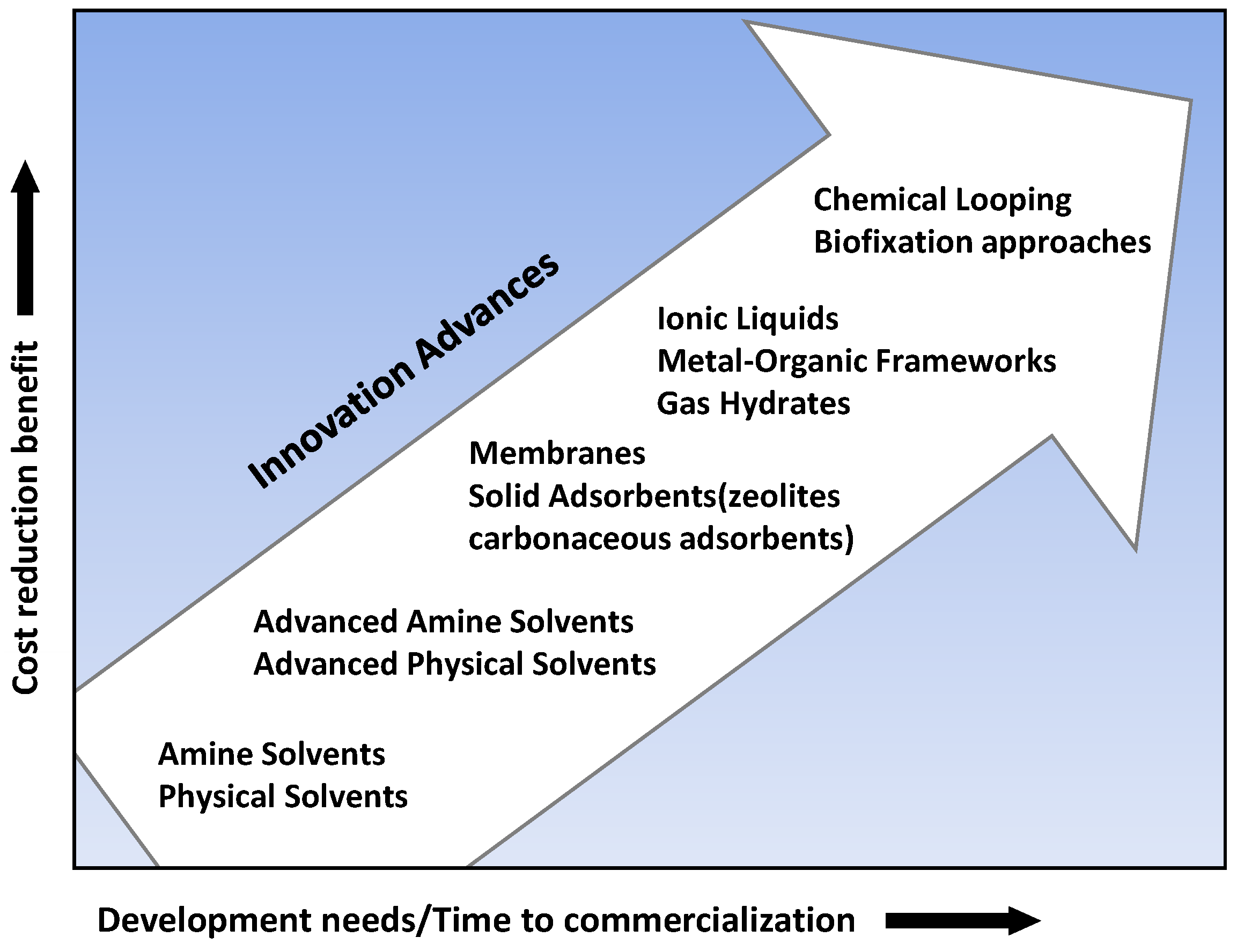
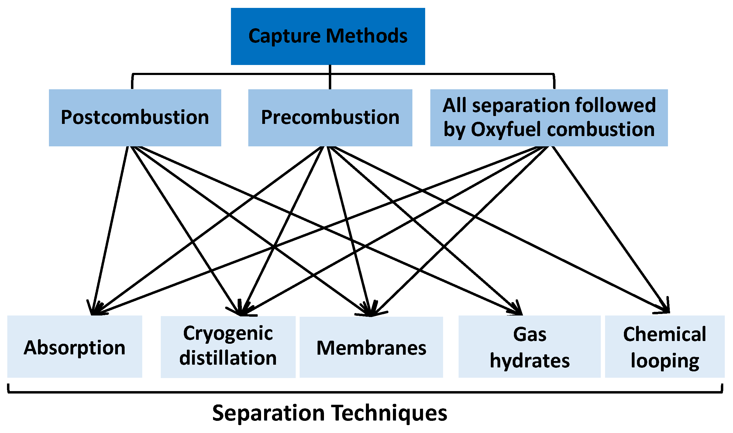
To reduce the time to commercialization, innovative new materials are needed for research, as shown in Figure 2 [18]. CO2 can be captured from post combustion, precombustion, or oxyfuel processes with a variety of promising new materials, as shown in Figure 3 [18].
Carbon sequestration of materials mainly goes through two stages: carbon capture and carbon sequestration. Carbon sequestration with carbonization reaction as the main mode has been extensively studied, but little attention has been paid to the performance of carbon capture [24]. Most of the previous work was done to enhance the carbon sequestration capacity of concrete by investigating the carbon dioxide carbonation reactions, but using the method that increasing the total amount of carbon sequestration to enhance the carbon sequestration capacity of cement-based materials has been ignored. However, as the first stage of carbon sequestration, carbon capture is the premise of carbon sequestration and determines the maximum amount of carbon sequestration. Therefore, by adding porous biochar into cement-based materials [24], the pore structure can reach the physical state of sudden change in transport property, and the carbon capture performance can be effectively improved, thus enhancing the carbon sequestration capacity of cement-based materials.
In this paper, Section 2 and Section 3 introduce the significance of using cement-based materials to absorb and fix carbon dioxide, as well as the basic characteristics of the carbonization process in cement-based materials, so that readers can identify the most basic research problems in the study of cement-based materials’ carbon fixation. On the basis of cement-based material carbon fixation performance, how to enhance its carbon fixation capacity is the main content of the Section 4. Finally, Section 5 gives the conclusion and prospect through the above introduction.

2. Significance of Cement-Based Materials for Carbon Dioxide Absorption

2.1. The Process of Producing Carbon Dioxide and Absorbing Carbon Dioxide

2.1.1. CO2 Production Mechanism

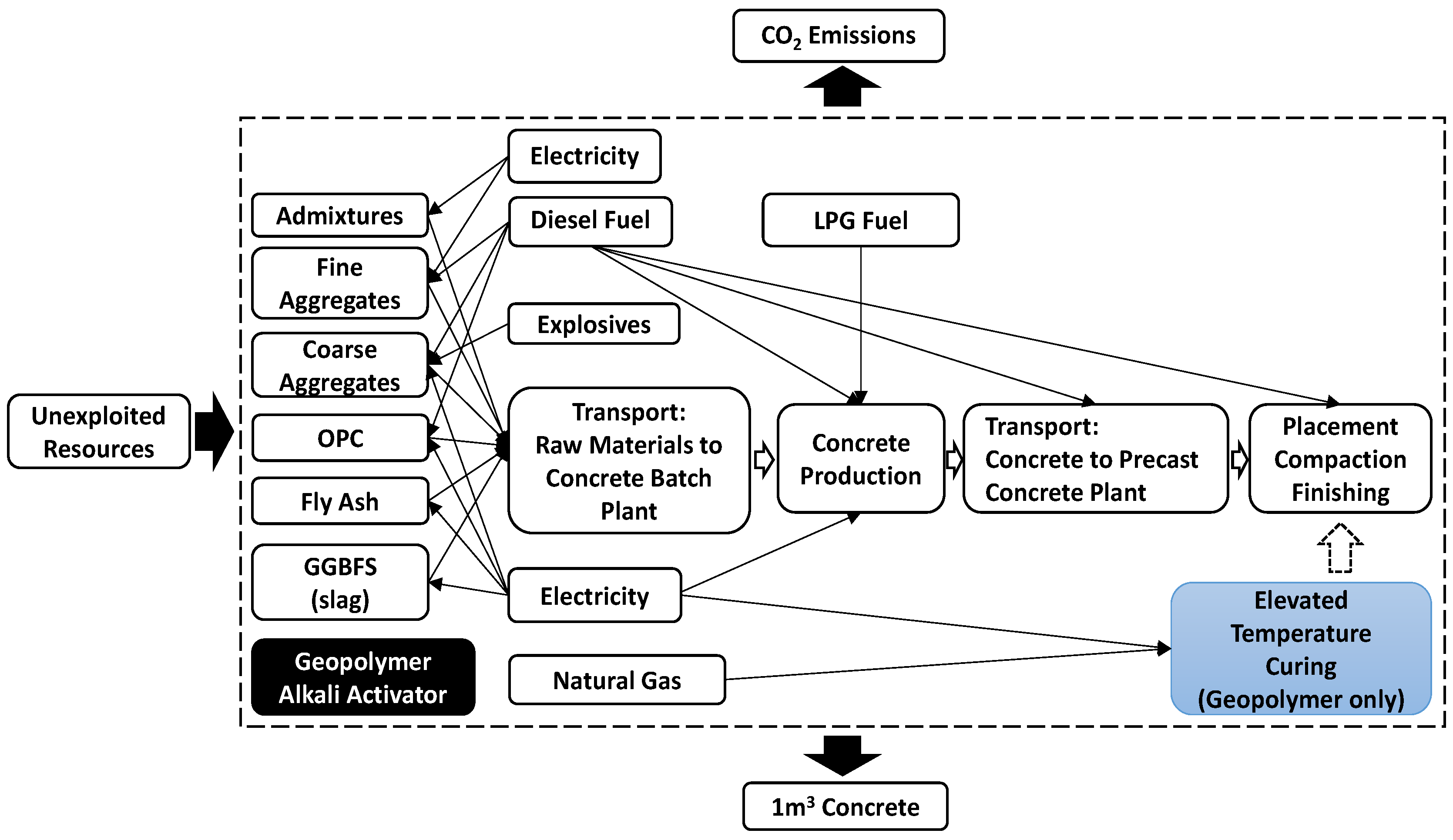
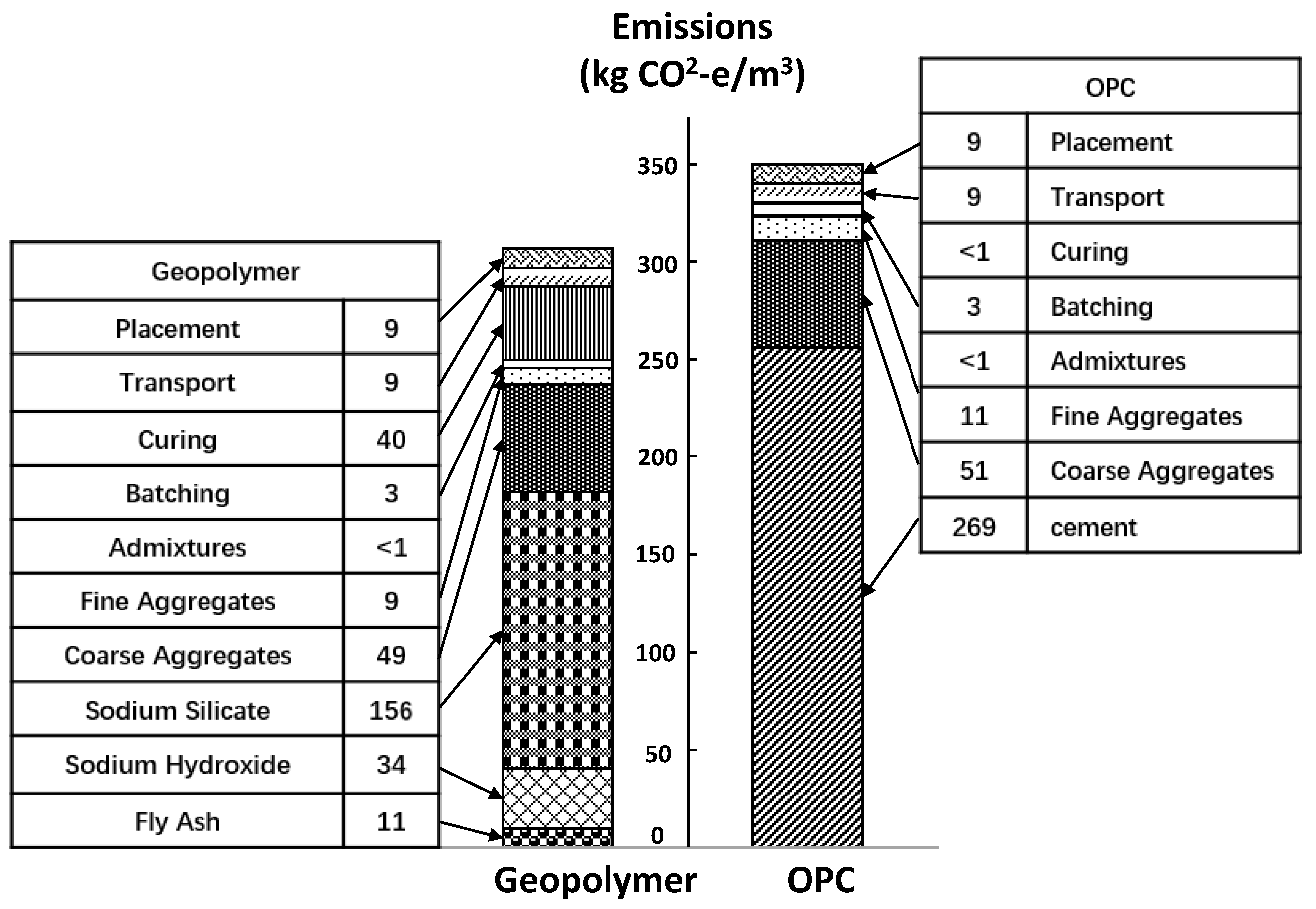
A concrete example, building materials have been used around the world for thousands of years, and as a result of cement manufacturing, significant amounts of these gases are released. Currently, each person consumes one m3 of water each year [25,26]. In Figure 4, we can see the amount of carbon dioxide produced during concrete production. In Figure 2, the study’s System Boundaries are shown. According to Figure 4, the mining industry is responsible for a certain amount of CO2 emissions (e.g., energy use), and raw materials are processed and manufactured. In the production of concrete, 1 m3 of concrete is constructed in phases. A summary of the key types of energy expended with each activity is also provided in Figure 4 [26]. In an assessment of each activity’s contribution to CO2-e, in order to manufacture and construct 1 m3 of concrete, raw materials need to be sourced and manufactured. Figure 5 summarizes the findings. A substantial portion of CO2-e for OPC concrete comes from Portland cement; it contributes 76.4% of CO2-e [26].
OPC production is associated with high CO2 emissions for several reasons. A key ingredient in the process is limestone, which is calcined and releases CO2 as a result. The manufacturing process consumes a lot of energy. Temperatures exceeding 1400 °C are used for heating raw materials in rotating kilns [25,26]. The calcination chemical process utilizes both energy and chemicals. Calcium oxide (CaO) is formed from limestone (calcium carbonate) according to chemical description, shown as Equation (1). Usually, between 60 and 65% of CaO’s total CO2 emissions are caused by combustion [10,27].
CaCO 3 = CaO + CO 2

2.1.2. CO2 Absorption Mechanism

Concrete undergoes a number of chemical reactions. Calcium oxide is thought to hydrate to calcium hydroxide (Ca(OH)2) as shown in the equation below [10]: During certain humid conditions, if the cement paste in concrete is exposed to carbon dioxide in the air, the cement paste will become weaker. In the presence of calcium hydroxide, dissociation may occur, described as Equation (2), and CO2 dissolves in water in the form of hydrogen carbonate (H2CO3*), shown as Equation (3); this leads to calcination, carbonation, and the reverse reaction; as described in Equations (4)–(6), there is evidence that it occurs. The following is a simplified description of the reactions that result in the formation of calcium carbonate (calcite), again described in Equation (7).
Ca ( OH ) 2 = Ca 2 + + 2 ( OH )
CO 2 ( g ) + H 2 O = H 2 CO 3 *
H 2 CO 3 * = H 2 CO 3
H 2 CO 3 = H + + HCO 3
HCO 3 = H + + CO 3 2
Ca 2 + + CO 3 2 = CaCO 3 ( s )
Overall, over the period 1930–2013, carbonate cement materials sequestered an estimated 4.5 GtC. As a result, 43% of the CO2 emissions from cement production were offset; during cement production, fossil fuel emissions are not included [28]. Furthermore, carbonation mechanism models have been studied by scholars since 2004. The following are examples: Concrete carbonation mechanisms were examined by Bary and Sellier [29]. Relative humidity evolutions in porous materials must be taken into account. Water mass balance equations were used to develop the model; a gaseous phase is characterized by carbon dioxide and a pore solution is characterized by calcium (Ca). This study was expected to provide a complete solution to the problem of cement carbonation due to atmospheric pollution [30].

2.2. Cement Industry’s Role in Balancing the Release of CO2

There are between 11.4 and 12.6 billion tons of concrete raw materials generated each year [1,12]. Carbon dioxide is shown to contain a number of species; calcite is not the only mineral, The stoichiometric potential to reverse the calcination process within cement paste samples is significant [10]. Alternatively, carbonation can be used. Calcium is formed from the reaction between hydrated cement and carbon dioxide; it has been tested under a wide range of conditions for its ability to sequester carbon dioxide, thereby balancing this release [10]. Therefore, the significance of carbon sequestration by applying cement-based materials is that the carbon neutrality of the cement industry can be achieved by the properties of cement itself.

2.3. The Ways to Reduce Emissions in the Cement Industry

Carbon capture is a technique for capturing carbon. The depths of the ocean or underground transport sequester CO2 as a stream of concentrated gas. This technique may be used to reduce CO2 emissions using carbon dioxide capture and storage (CCS). There is a possibility of capturing and storing carbon dioxide for a very long time. CCS technologies can reduce CO2 emissions by 65–70% in cement production, according to Newell and Anderson [31]. Cement is manufactured in the following way: a fuel is burned to provide heat for the process of converting CaCO3 to CaO, generating CO2 [32]. Researchers have developed different methods of capturing CO2 during combustion [33]. Cryogen separation, membrane separation, chemical stripping, and physical absorption are some of the techniques. None of these options has a clear estimate of the implementation cost; there is a direct relationship between fuel type and technical performance [33,34]. In addition to these options, the cement industry also has a number of other possible capture processes, capturing post-combustion emissions, the capture of combustion gases and pre-combustion gases [8,34,35].
Clinker production is an energy intensive process, which emits significant amounts of CO2 [36]. Carbon dioxide emissions can be reduced most effectively by reducing the amount of clinker in blended cement [6]. Burning waste or biomass as an alternative fuel can reduce carbon dioxide emissions. Because cement kilns have a high process temperature, they are ideal for the combustion of waste [37]. Improved pyro processing will provide the greatest benefits for reducing cement manufacturing’s energy consumption and emissions [6].

3. Carbonation of Concrete: An Investigation of Its Basic Characteristics

3.1. The Factors Affecting Carbonization

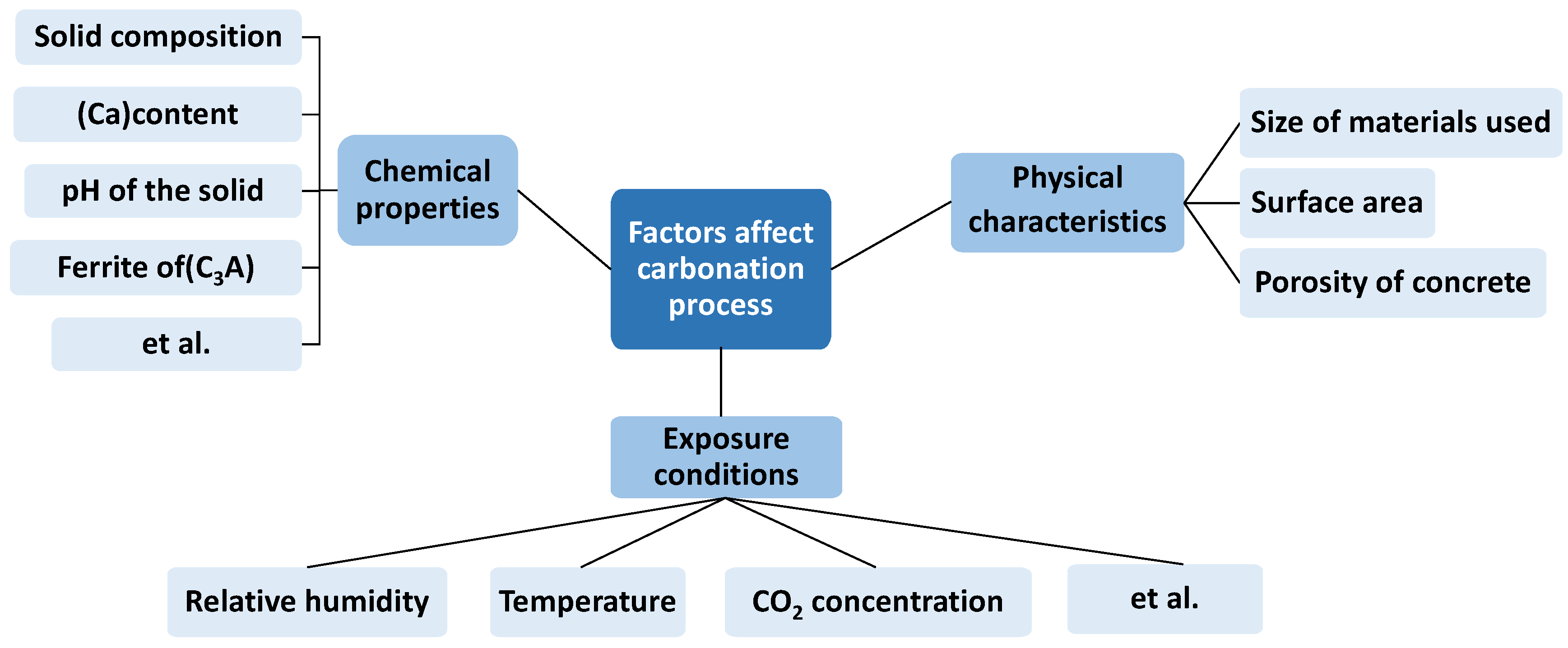
Calcite sequestration in concrete in the form of carbonation depends on a variety of factors. The relative humidity of the curing environment is one of these factors, The composition of the atmosphere is determined by temperature and CO2 concentration [38]. Additionally, alongside the chemical properties of a material, it is also important to consider solid physical characteristics as well as exposure conditions when evaluating carbonation. Figure 6 illustrates this. Additionally, the water–cement ratio (w/c) and concrete density affect concrete carbonation in a significant way by increasing or decreasing carbonation rates—concrete that is aerated, in particular [1].
Crystallization products are affected by temperature [30]. Concrete’s carbonation depth and compressive strength are linearly related to their temperature, according to experimental results [30]. CO2 and carbonate ions diffuse faster at higher temperatures, and the carbonation reaction runs faster [39]. Increasing the temperature will result in, transmission coefficients and reaction coefficients being high. Consequently, concrete specimens are more affected by carbonation and reaction rates [30].
The high humidity may slow down the carbonation of a filling material or road base. There may be a faster rate of leaching than carbonation in this case. When water is exposed to carbon dioxide, it will carbonate. The carbonation process seems to be accelerated by cyclic wetting and drying. Since concrete without water does not form ions and calcite, it does not carbonate since it lacks the water needed for ion formation and calcite formation. Wet conditions also slow carbohydrate oxidation. In this case, the carbonation rate reaches its maximum at a high relative humidity. RH will determine this maximum. The binder must have a specific porosity and type. In addition, capillary geometry plays a role. The ratio of water to binder determines this in practice, hydrogenation and binder type. Carbon moves fastest when RH (inside the concrete) is between 60 and 80% [39]. RH is related to carbon depth and compressive strength through a quadratic and cubic function, respectively. When the relative humidity reaches 70%, concrete’s carbonation depth reaches its maximum [30].
A surface-to-inner reaction causes carbonation. Due to this, it will be important to measure the surface area exposed. Generally, diffusion will occur in the porosity, but cracks, interfacial zones, and the interstitial zone must also be considered. Carbonation will occur faster in the interfacial zone because it is more porous. A deeper carbonation can be observed in thin slices of paste at the point of contact with stones. The carbon dioxide can reach deeper in surface cracks and react with a larger surface area [40]. Thin sections of cracks with carbonated walls clearly demonstrate this. Hence, durability and deterioration will also affect carbonation. The carbonation of concrete will be enhanced if it is affected by alkali silica or delayed ettringite reactions, for example. Fresh concrete surfaces created by falling concrete pieces will lead to a higher level of carbonation [39].
Generally speaking, with longer carbonation time, higher CO2 concentration, as the CO2 pressure increases, the mortar will be able to absorb more CO2 and have a higher compressive strength [41]. Carbonation and compressive strength are related to carbon dioxide concentration by power and exponential functions, respectively [30]. Even though CO2 is used to accelerate the process, this technique is still hindered by slow carbonation speeds. Concrete that is of a young age is carbonated at a slower rate due to the diffusion of CO2 into the matrix. It takes a very long time [42].

3.2. Modeling Carbonization Mathematically

As seen from the perspective of civil engineering, a very important problem is the analysis of its dynamics. As reported in the article, the models used in this study do not provide precise proofs of carbon dioxide transport, but we report some mathematical results regarding it [43].
In calculations of concrete carbonation based on mathematical results, a mathematical model of concrete carbonation was proposed as a free boundary problem for a one-dimensional carbonated front [44]. A solution to this problem was proven to exist and to be unique. The free boundary has been proven to behave in a large time range. In order to analyze the dynamics of the concrete carbonation process, we will construct a mathematical model of this process in three dimensions. This study begins with a review of the literature. Maekawa–Ishida–Kishi and Maekawa–Chaube–Kishi introduced the hysteresis operator into the mathematical model of moisture transport proposed [45,46,47,48]. This model has a unique solution, which has been proven to exist. A solution to this model is unique for this reason [43,49,50,51]. The following balanced law of carbon dioxide transport according to previous research [46,47] was proposed [50,51] as shown in Equations (8) and (9).
t { ϕ ( z ) [ ( 1 S ) v + S u ] } div ( ϕ ( z ) [ H 1 ( 1 S ) v + H 2 S u ) = k u w in   Q ( T ) : = ( 0 , T ) × Ω
w ( t ) = w ( 0 ) e k ˜ 0 t u ( r ) d r u ( t ) ,   z ( t ) = 1 e k ˜ 0 t u ( r ) d r   f o r   t > 0
Ω : domain occupied by concrete.
v = ( t , x ) and u = u ( t , x ) : the concentration of carbon dioxide in air and the concentration of carbon dioxide in water at a time t and a position x Ω , respectively.
v = ρ 0 u holds for a positive constant ρ 0 by Henry’s law.
ϕ = ϕ ( z ) : the porosity, which is the ratio of the volume of the total pore spaces inside the concrete to the volume of the whole concrete.
z: the ratio of the volume of consumed calcium hydroxide to the volume of the total calcium hydroxide.
S: the degree of saturation corresponding to the relative humidity, and the relationship between the relative humidity and the degree of saturation is given as a hysteresis operator in [46,47].
H 1 = H 2 : positive constants.
k is a reaction rate.
w : the concentration of calcium ion and this forcing term represents the consumed carbon dioxide in the concrete carbonation process and is given by the reaction rate theory.
The following simplified Equation (10) with the boundary and initial condition was also studied.
t [ ϕ ( 1 e 0 t u ( r ) d r ) u ] Δ u = w 0 u e 0 t u ( r ) d r in   Q ( T ) : = ( 0 , T ) × Ω u = u b   on   S ( T ) : = ( 0 , T ) × Ω u ( 0 ) = u 0   i n   Ω
where u b is a given function on Q ( T ) , and w 0 and u 0 are given functions on Ω . In this paper, we show the existence and uniqueness of a time global solution of the problem (P) = {(1.5), (1.6), (1.7)} and the large time behavior of that solution.

3.3. Method for Detecting Carbonation

According to what was previously mentioned, concrete carbonation has been studied by many researchers. The majority of studies use thermal gravimetric analyses and focus on calcite or other forms of solid calcium carbonate as a source of carbon dioxide in concrete. Vaterite and aragonite are examples. The TGA process involves heating samples and measuring their mass loss as a function of temperature. There are many processes that can cause mass loss. In some cases, the compounds become gaseous due to evaporation or chemical breakdown. Carbon dioxide and water are examples of these gases [10]. Table 1 shows the temperature ranges in various studies.
Comparative thermal analysis (DTA) was the method of choice for analyzing compound compositions in earlier studies. A constant heating condition will cause a change in temperature in a sample. It would be an endothermic reaction if the rate of temperature increases decreased, and the reaction would be exothermic if there was an increase. An investigation of the properties of cement was published by Ramachandran et al. [58]. Around 850 °C is the temperature at which calcite decomposes [10].
The compounds in hydrated cement, however, are very diverse; under various conditions, concrete’s chemistry varies, and the chemistry of concrete as it ages is not completely understood. As a consequence, assumptions have to be made regarding the predominant species that emerge at different temperatures. Since these factors are unknown, the process of analyzing thermal decomposition using mass spectroscopy. The temperature-programmed desorption method (TPD) is used in these experiments [10]. After heating the sample again, it is subjected to TPD. The sample is passed over an inert stream of known gases. As a result, gas is released from the sample. Based on amperage for various molecular weights, the composition of the combined released and inert gas streams is determined by passing the stream through a gas analysis system. Once again, it is difficult to distinguish all species, but there is still a great deal of information that can be obtained [10].
Moreover, the composition of carbonized products can be determined with thermogravimetric analysis (TGA) in conjunction with scanning electron microscopy (SEM) and Fourier transform infrared spectroscopy (FTIR). The carbonated surface layer is composed of calcium silicate hydrate and CaCO3 [61].

3.4. Applications and Findings of Carbonation Research

The amount of carbon species that are absorbed in relatively young cement pastes other than calcite does not exceed that in mature cement pastes. There is a slight increase in these absorbed species in samples that are exposed to air and have some additional moisture added. Moreover, calcium hydroxide and calcium carbonate may be present as “hydrated” complexes or absorbed species in cement pastes in addition to their solid phases [10].
A carbonated layer with a thickness of less than 1.6 mm was obtained after the CO2 treatment, strengthened compressively by a small amount. However, the permeability of the water was significantly reduced. The mortars transmit water vapor and migrate chloride [61]. Additional protection could be provided by the CO2 surface treatment. To begin with, an enhanced outer layer was created by the carbonated surface layer. Since the carbonated samples do not undergo carbonation, the embedded reinforcement bars are passivated with high alkalinity. In the second place, during surface CO2 treatment, chloride ions might diffuse slower, while during weather carbonation, they may diffuse more quickly. Then, furthermore, the results of FTIR and TGA indicate that CaCO3 and silica gel were not completely formed from CSH after CO2 treatment. Among C-S-H compounds, only Ca/Si decreased. Therefore, there are still some C-S-H gels left on the market. During early hydration, mostly outer CSH is formed, which is more porous and has a higher Ca/Si ratio [43]. It is possible that this C-S-H could react more easily with CO2 and produce less porous products. This reaction resulted in a decrease in total solid volume; however, several more hydration products were used to fill up the space [61].

4. The Methods Increasing Concrete’s Ability to Adsorb Carbon

Carbon dioxide is mostly captured and stored through physical methods, methods based on chemicals and biology. CO2 is mainly captured and stored physically by mechanical means, including injection of high-concentration CO2 into underground rock formations (mined oil and gas wells, coal seams, and deep seas). The process can be used to capture and store large amounts of carbon dioxide at a relatively low cost, and it is suitable for large-scale energy storage [1,62]. If there is movement in the crust, there is a possibility of CO2 seeping out from deep rock formations that have been stored for a long time; capturing and storing data is more expensive and riskier. CO2 is captured and stored chemically through chemical reactions with chemical capture reagents (alkaline compounds or catalysts) to form alcohols, carboxylates, carbonates, etc. [63,64,65]. Compounds containing alkalis are usually used to capture CO2 using hydroxides, alkanolamines, and carbonates. As an example, the hydroxide NaOH can be formed by capturing CO2 to form Na2CO3. NaOH industries consume a large amount of electricity. China and the EU account for 5% and 3%, respectively, of the industrial sector [66]. There are several types of alkanolamines, including monoethanolamine (MEA). As a result, CO2 emissions are captured and stored. A significant amount of energy is consumed during the regeneration process, however (about 80%) [67]. One ton of carbon dioxide is captured. Water-washing will cause MEA emissions ranging from 0.1 to 0.8 kg [68]. The human body can be harmed by NaOH and MEA [66,68]. CO2 emissions associated with processes can be reduced through the use of chemicals for CO2 capture, The carbon-capturing bacteria, however, consume more energy and pollute the environment more than they do. Carbon-capturing bacteria do not produce harmful by-products as urease-producing bacteria do [69]. There is no difference between the cultivation of carbon-capturing bacteria and that of UPB in terms of ease of cultivation. There is usually a cost associated with preparing CO2 catalysts. Extreme conditions of use, several factors make catalytic storage conversion difficult at large scales, including low efficiency. Catalysts should be used at a limited scale. Methods used in biology, organisms and biological enzymes capture and store CO2 and convert it into compounds such as glucose, carboxylic acids, and carbonates [9,70,71]. The carbon adsorption of different materials in literatures is summarized in Table 2.

4.1. The Physical Method

The economics and costs of process design must be considered when assessing a new material’s potential [19]: whether it is eco-friendly, low-carbon, and has a low production cost, which translates into high economic benefits for the company, resulting in a large adsorption capacity for CO2. A biochar-based cementitious composite could also improve carbon sequestration performance through the use of biochar. By pore adsorption, biochar stores and captures CO2 because of its high specific surface area and strength affinity for nonpolar substances [77].
Due to its many advantages, such as low cost, activated carbon (AC) is the best solid adsorbent. With a structure of pores that can be designed easily, an area of great size, it also regenerates easily [78]. There is a growing demand for activated carbon from abundant sources as sorbents in small-scale industries. There is a good case for using low-cost precursors like lignocellulosic biomass to reduce CO2 emissions. In the production of activated carbon, agricultural waste can serve as a precursor [79]. There have been a number of examples where agricultural biomass has been used as precursor for carbon adsorbents for CO2 adsorption, including molasses [80], walnut shells [81], corn cobs [82], date seeds [83], rice straw [84], and cotton stalk [85]. However, molasses, walnut shells, corn cobs, and rice stalks have not yet been studied in this manner [18].
Globally, activated carbon is estimated to be produced at 100,000 tons per year [50]. In the production of AC based on biomass, two typical activation methods are utilized: chemical and physical activation. The combination of chemical and physical activation might be a promising technology for improving the porosity and textural properties of ACs [86,87]. Biochar materials and related studies are shown in Table 3.
The amount of biochar added to cementitious composites affects their compressive strength. Regardless of the ratio of water to cement, adding biochar to cement mortar increases its early strength [52]. The critical amount of biochar is usually between 4% and 6% and can enhance or reduce the composite’s mechanical properties depending on how much biochar is added [99,100]. An increase of strength was observed at 7 and 28 days following the addition of 2–3% biochar [101,102,103]. A composite’s mechanical properties are adversely affected when excessive amounts of the material are incorporated. By Tan et al., a biochar content of more than 5% was shown to accumulate, which will result in an increase in cracks and macropores and a decrease in hydration products [104,105,106]. Incorporating 2% mixed particle size biochar rather than cement at 3 and 7 days increased the mortar compressive strength compared to using a single particle size biochar mixture in a 1:1 ratio [107].
Strength of concrete: both water-cured concrete and dry-cured concrete could be strengthened by adding biochar from wood waste, A maximum of 5% of wood biochar could be incorporated, with a significant decrease in tensile strength when excessive amounts were used [106]. Biochar introduced pores into cement mortar, which resulted in a decrease in tensile strength. Due to inhomogeneity, the tensile plane is weaker in areas where biochar particle concentration exceeds 6.5% [108,109]. Concrete’s overall strength is reduced due to the aggregation effect of biochar particles, leading to local weak zones [110].
When woody biochar was added to cement paste, the maximum flexural strength gain was observed. As the biochar content increased, the flexural strength decreased [108]. Biochar’s porous structure introduced pores in the tensile plane, leading to a decrease in flexural strength. This phenomenon increases the cracking potential of cement by causing more weak interfacial weak zones and porous cement into which biochar has been incorporated instead of cement, at a concentration of 10% biochar. Despite the small decrease in flexural strength, at 15% doses, the strength significantly decreased by 12.9% [106,111].
Additionally, hemp concrete in comparison to Portland cement has been shown to have a lower ecological impact. An essential part of hemp concrete is the use of lime-based binder mixed with hemp fiber. The aggregates in this type of concrete are cellulose matter (hemp, in this case), which suggests that the aggregates are made from cellulose matter. A lot of attention has also been drawn to LHC as a material that emits less carbon dioxide than it absorbs (carbon negative) [112]. Increasing densities of samples result in increasing compressive strength directly proportionately. Material density contributes significantly to the material’s mechanical strength, although the strength of the material is a function of the binding-to-hemp-mass ratio in conjunction with the water-to-binding-mass ratio [112].
The LHC has a negative impact on carbon; LHC absorbs more carbon dioxide during its manufacturing cycle than it produces [112]. By undergoing photosynthesis and carbonation, the slaked lime present in the mixture absorbs carbon dioxide through carbonation. It is possible for lime mortars to sequester carbon dioxide during their service life since they undergo a long process of carbonation [112].
Cement-based material carbon sequestration happens mainly through the two carbon capture and carbon sequestration stages. Carbon sequestration with carbonization reaction as the main way has been studied a lot, but there has been little attention to carbon capture performance. However, as the first stage of carbon sequestration, carbon capture is the premise of carbon sequestration and determines the maximum amount of carbon sequestration. By adding porous biochar into cement-based materials and changing the pore structure to enhance the transmission [24], the carbon capture performance is effectively improved, thus enhancing the carbon fixation capacity of cement-based materials.
To improve the carbon capture capability of building materials by considering the pore structure combination of biochar and building materials, this work is designed to determine an effective pore structure combination. In order to design pore structures for target materials, a model that changes pore structure connectivity is applied. As a result, its mechanical properties are improved through the application of a layered structure. Based on the results of the study, it appears that the pore structure connectivity changing model is applicable. Increasing the ratio of water to cement from 0.25 to 0.4 will result in an increase in the cost of building material from 10% to 148%, and biochar increases the effectiveness of carbon capture by target materials. As biochar’s dosage or size increases, its improvement capacity increases as well. A layered structure with a water-to-cement ratio of 0.25 also increases compressive and three-point flexural strength by, respectively, 44% and 28% when compared with a regular structure [24].

4.2. The Chemical Method

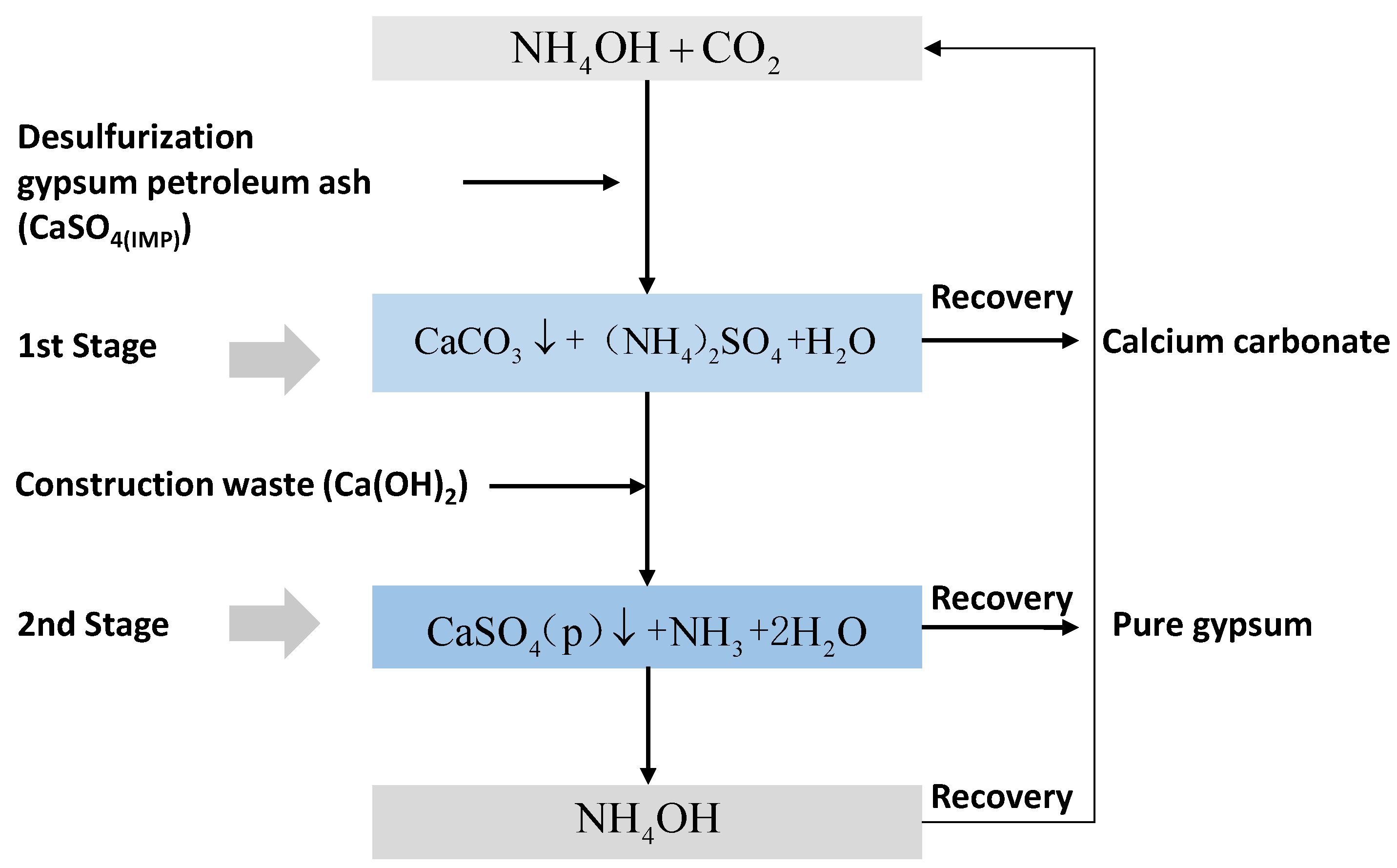
To improve the efficiency and effectiveness of the process, the most important step in the process of capturing and utilizing carbon (CCU) is selecting the absorbent. Ammonia was tested to see if it could intercept and absorb CCU as a liquid during the process [113]. The following are the mechanisms for constructing a recyclable CCU process from gypsum and ammonium sulfate used in fertilizer manufacturing [113].
The basic carbonation mechanism from Equations (11)–(14) illustrates the basic concept of the CCU process. H2CO3, HCO 3 , and CO 3 2 are dissolved carbon dioxide forms that are segregated according to pH. A metal carbonate can be formed from carbon dioxide. For precipitated calcium carbonate (PCC), carbonation reaction can be applied in accordance with the basic carbonation mechanism. Equations (15)–(17) show how ammonia absorbent works. Figure 7 shows a flowchart of the mechanisms presented above [113].
  • Basic carbonation mechanism
CO 2 CO 2 ( aq )
CO 2 ( aq ) + OH HCO 3
H 2 O ( l ) + CO 2 ( aq ) H 2 CO 3 2 H + + CO 3 2
M 2 + + CO 3 2 MCO 3
2.
Mechanism applied to ammonia absorbent
NH 4 OH ( aq ) + CO 2 ( g ) NH 4 HCO 3 ( aq )
NH 4 HCO 3 + CaSO 4 ( imp ) CaCO 3 ( s ) + ( NH 4 ) 2 SO 4 ( aq ) + CO 2 ( g ) + H 2 O
( NH 4 ) 2 SO 4 + Ca ( OH ) 2 CaSO 4 ( p ) + 2 NH 3 + 2 H 2 O
As a liquid absorbent, ammonia was used as part of this research to reduce carbon dioxide usage. It was determined that ammonia has the potential to act as an excellent absorbent after investigating the possibility of each step. Despite precipitated calcium carbonate’s calcite crystal structure, it was formed under norm pressures and temperatures, and vaterite was a major structure of PCC formed in this research. The recycled ammonia solution was used again to absorb gypsum dihydrate, although the absorption performance was slightly lower than the initial state [113].
A cementitious material rich in calcium absorbs CO2 well, so it does not need to be augmented with additional absorbents. Figure 7 illustrates how this concept can be implemented using a two-step mixing method. Cementitious materials are prepared by mixing calcium-rich materials with dry ones. A second step produces concrete by adding OPC, aggregates, and admixtures to the slurry and reacting bubbled carbon dioxide with calcium ions. A calcium-rich cementitious material is carbonated with CO2 in this step of the proposed method. The pre-carbonation method refers to the process of carbonating concrete before it is poured [42]. SEM studies showed that pre-carbonation can produce nanoparticles and sub microparticles of CaCO3 incorporating heterogeneous nucleation sites for OPC hydration. At the young age of cement manufacturing, isothermal calorimetry tests confirmed significant hydration [42].

4.3. The Microorganism’s Method

There are many types of research being conducted today on biological sequestration. Since this method is cheap and eco-friendly, it is being used to assess the effectiveness of removing CO2 from the atmosphere [114]. Bio-mineralization is the process of making calcium carbonate (CaCO3) and magnesium carbonate (MgCO3) from CO2 by bacteria that produce carbon anhydrase (CA) and urease enzymes [115]. As a result, soil bacteria sequester CO2 as a result of their actions. Nevertheless, soil chemical properties can negatively affect bio-sequestration [116]. Thus, inoculating bacteria into a system of sequestration might accelerate the process [1].
A calcium and magnesium ion solution can adsorb CO2 and transform it into carbonates. Energy efficiency is another aspect of the mineralization/carbonization process, in addition to being environmentally friendly. Materials such as cement, steel slag, and limestone can be mineralized/carbonized to provide calcium and magnesium. Carbon-capturing bacteria and CO2 are used to capture carbon from waste concrete. This microbial process can increase the mechanical properties of recycled concrete aggregates, as well as making cement-based materials more resistant to efflorescence. It is essential to suppress dust on construction sites. By utilizing these potential applications, CO2 can be used as a reference value in construction materials. When bacteria capture carbon dioxide, they adsorb and convert it into carbonates. A construction material’s properties can be improved through bio-mineralization or carbonization.
The process of biomineralization/carbonization is environmentally friendly. Recent advances in concrete surface treatment have been made by calcium carbonate precipitation owing to its good stability. Mineralization can be induced either by bacterial action or by hydrolysis of dimethyl carbonate (DMC). The bacterial carbonate precipitation technique has been shown to be effective in a number of studies [117,118,119]. Compared to untreated glass, it decreased water absorption by 20–80%, gas permeability by 17–33%, and chloride permeability by 39–51%. Bacterial treatment significantly reduced porosity in mortar, as demonstrated by Achal et al. [61,117].
Construction materials can be converted into cementitious materials by carbon-capturing bacteria. This can improve mechanical properties and aesthetics, while sequestering carbon at the same time. Solid wastes and cement-based materials contain MgO and CaO that can well consolidate CO2 [9].

5. Conclusions and Prospect

(1)
Carbon dioxide has been sequestered in carbonating cement materials for a cumulative amount of 4.5 GtC since 1930. Over the same period, this project offset 43% of cement’s CO2 emissions. It does not include the fossil fuel emissions generated during cement production. The reverse process, carbonation in concrete, balances the release of carbon dioxide. Therefore, the significance of carbon sequestration by applying cement-based materials is that carbon neutrality of the cement industry can be achieved by the properties of cement itself.
(2)
Calcite sequestration into concrete is affected by various factors, including carbonation and acceleration. Temperature, relative humidity, and CO2 concentration are some of these curing conditions. Furthermore, solid physical characteristics as well as the material chemical properties affect carbonation. The aerated concrete carbonation rate is influenced significantly by concrete density and water–cement ratio (w/c), particularly by density and w/c ratio.
(3)
Carbon sequestration of materials mainly goes through two stages: carbon capture and carbon storage. As the first stage of carbon sequestration, carbon capture is the premise of carbon sequestration and determines the maximum amount of carbon sequestration. By optimizing the porous structure of cement-based materials to enhance the transmission to effectively improve the carbon capture performance, it can effectively enhance the carbon sequestration capacity. Carbon sequestration with carbonization reaction as the main way has been studied a lot, but there is little attention to carbon capture performance. Therefore, enhancing the carbon sequestration capacity of cement-based materials by increasing the total amount of carbon sequestration needs more attention, which can become an important research direction in the field of carbon sequestration by cement-based materials.
(4)
The future work in capturing carbon dioxide in concrete can be conducted based on the percolation theory and by changing the pore structure of concrete to improve the carbon sequestration capacity. The research direction includes changing the pore structure of concrete itself and changing the pore structure of concrete by adding porous materials.

Author Contributions

Conceptualization, X.L. and R.L.; methodology, Y.W.; validation, Y.W., X.L. and R.L.; formal analysis, Y.W.; investigation, Y.W.; resources, R.L.; data curation, Y.W., X.L. and R.L.; writing—original draft preparation, Y.W.; writing—review and editing, X.L.; visualization, Y.W.; supervision, X.L. and R.L.; project administration, R.L.; funding acquisition, X.L. and R.L. All authors have read and agreed to the published version of the manuscript.

Funding

The work is supported by the Guangdong Basic and Applied Basic Research Foundation (2021A1515011808), National Natural Science Foundation of China (52105307), Shenzhen Science and Technology Program (RCBS20210609104444087), Research Funding of Post-doctoral Who Came to Shenzhen (4103-6021271018K1), Scientific Research Start-up Project of Shenzhen Polytechnic (4103-6022312030K), Ningxia Key Research and Development Plan Foreign Science and Technology Cooperation Project (2022BFE03003).

Data Availability Statement

Data available within the article or its supplementary materials.

Conflicts of Interest

The authors declare that they have no conflict of interest.

References

  1. Alshalif, A.F.; Irwan, J.M.; Othman, N.; Al-Gheethi, A.A.; Shamsudin, S. A systematic review on bio-sequestration of carbon dioxide in bio-concrete systems: A future direction. Eur. J. Environ. Civ. Eng. 2022, 26, 1209–1228. [Google Scholar] [CrossRef]
  2. Anand, S.; Vrat, P.; Dahiya, R.P. Application of a system dynamics approach for assessment and mitigation of CO2 emissions from the cement industry. J. Environ. Manag. 2006, 79, 383–398. [Google Scholar] [CrossRef]
  3. Hendriks, C.A.; Worrell, E.; De Jager, D.; Blok, K.; Riemer, P. Emission reduction of greenhouse gases from the cement industry. In Proceedings of the Fourth International Conference on Greenhouse Gas Control Technologies, Interlaken, Switzerland, 30 August–2 September 1998; IEA GHG R&D Programme: Interlaken, Austria, 1998; pp. 939–944. [Google Scholar]
  4. Gonzalez, J.L.A. Technology Change and Environmental Management for Cement Manufacturing: The Cement Industry in the United States (2004–2050). Doctoral Dissertation, Carnegie Mellon University, Pittsburgh, PA, USA, 2005. [Google Scholar]
  5. World Business Council for Sustainable Development. The Cement Sustainability Initiative. Cement Industry Energy and CO2 Performance. 2010. Available online: http://www.wbcsd.org/DocRoot/LDqFZHcewCUmDh4v02pN/csi-gnr-reportwith-label.pdf (accessed on 17 September 2010).
  6. Ali, M.B.; Saidur, R.; Hossain, M.S. A review on emission analysis in cement industries. Renew. Sustain. Energy Rev. 2011, 15, 2252–2261. [Google Scholar] [CrossRef]
  7. Deja, J.; Uliasz-Bochenczyk, A.; Mokrzycki, E. CO2 emissions from Polish cement industry. Int. J. Greenh. Gas Control 2010, 4, 583–588. [Google Scholar] [CrossRef]
  8. Hoenig, V.; Hoppe, H.; Emberger, B. Carbon Capture Technology—Options and Potentials for the Cement Industry; Tannenstrasse: European Cement Research Academy: Düsseldorf, Germany, 2007; p. 96. Available online: http://www.ecraonline.org/downloads/RepCCS.pdf (accessed on 16 August 2010).
  9. Qian, C.; Yu, X.; Zheng, T.; Chen, Y. Review on bacteria fixing CO2 and bio-mineralization to enhance the performance of construction materials. J. CO2 Util. 2021, 55, 101849. [Google Scholar] [CrossRef]
  10. Haselbach, L. Potential for carbon dioxide absorption in concrete. J. Environ. Eng. 2009, 135, 465–472. [Google Scholar] [CrossRef]
  11. Huntzinger, D.N.; Eatmon, T.D. A life-cycle assessment of cement manufacturing: Comparing traditional process with alternative technologies. J. Clean. Prod. 2009, 17, 668–675. [Google Scholar] [CrossRef]
  12. Meyer, C. The greening of the concrete industry. Cem. Concr. Compos. 2009, 31, 601–605. [Google Scholar] [CrossRef]
  13. Monteiro, P.J.M.; Miller, S.A.; Horvath, A. Towards sustainable concrete. Nat. Mater. 2017, 16, 698–699. [Google Scholar] [CrossRef]
  14. Damineli, B.L.; Kemeid, F.M.; Aguiar, P.S.; John, V.M. Measuring the eco-efficiency of cement use. Cem. Concr. Compos. 2010, 32, 555–562. [Google Scholar] [CrossRef]
  15. Fang, J.; Yu, G.; Liu, L.; Hu, S.; Stuart Chapin, F. Climate change, human impacts, and carbon sequestration in China. Proc. Natl. Acad. Sci. USA 2018, 115, 4015–4020. [Google Scholar] [CrossRef] [PubMed] [Green Version]
  16. Yoon, I.S.; Çopuroğlu, O.; Park, K.B. Effect of global climatic change on carbonation progress of concrete. Atmos. Environ. 2007, 41, 7274–7285. [Google Scholar] [CrossRef]
  17. Pachauri, R.K. Climate Change 2014: Synthesis Report. Contribution of Working Groups I, II and III to the Fifth Assessment Report of the Intergovernmental Panel on; IPCC: Geneva, Switzerland, 2014.
  18. Kiełbasa, K.; Bayar, Ş.; Varol, E.A.; Sreńscek-Nazzal, J.; Bosacka, M.; Michalkiewicz, B. Thermochemical conversion of lignocellulosic biomass-olive pomace-into activated biocarbon for CO2 adsorption. Ind. Crops Prod. 2022, 187, 115416. [Google Scholar] [CrossRef]
  19. D’Alessandro, D.M.; Smit, B.; Long, J.R. Carbon dioxide capture: Prospects for new materials. Angew. Chem. Int. Ed. 2010, 49, 6058–6082. [Google Scholar] [CrossRef] [PubMed] [Green Version]
  20. Ahn, C.K.; Lee, H.W.; Chang, Y.S.; Han, K.; Kim, J.Y.; Rhee, C.H.; Chun, H.D.; Lee, M.W.; Park, J.M. Characterization of ammonia-based CO2 capture process using ion speciation. Int. J. Greenh. Gas Control 2011, 5, 1606–1613. [Google Scholar] [CrossRef]
  21. Leung DY, C.; Caramanna, G.; Maroto-Valer, M.M. An overview of current status of carbon dioxide capture and storage technologies. Renew. Sustain. Energy Rev. 2014, 39, 426–443. [Google Scholar] [CrossRef] [Green Version]
  22. Naucler, T.; Campbell, W.; Ruijs, J. Carbon Capture and Storage: Assessing the Economics; Office of Scientific and Technical Information: London, UK, 2008.
  23. Figueroa, J.D.; Fout, T.; Plasynski, S.; McIlvried, H.; Srivastava, R.D. Advances in CO2 capture technology—the US Department of Energy’s Carbon Sequestration ProgramJ. Int. J. Greenh. Gas Control. 2008, 2, 9–20. [Google Scholar] [CrossRef]
  24. Liu, R.; Xiao, H.; Guan, S.; Zhang, J.; Yao, D. Technology and method for applying biochar in building materials to evidently improve the carbon capture ability. J. Clean. Prod. 2020, 273, 123154. [Google Scholar] [CrossRef]
  25. Gartner, E. Industrially interesting approaches to “low-CO2” cements. Cem. Concr. Res. 2004, 34, 1489–1498. [Google Scholar] [CrossRef]
  26. Turner, L.K.; Collins, F.G. Carbon dioxide equivalent (CO2-e) emissions: A comparison between geopolymer and OPC cement concrete. Constr. Build. Mater. 2013, 43, 125–130. [Google Scholar] [CrossRef]
  27. Mehta, P.K.; Monteiro, P.J.M. Concrete Structure, Properties, and Materials, 2nd ed.; Prentice-Hall: Englewood Cliffs, NJ, USA, 1993. [Google Scholar]
  28. Xi, F.; Davis, S.J.; Ciais, P.; Crawford-Brown, D.; Guan, D.; Pade, C.; Shi, T.; Syddall, M.; Lv, J.; Ji, L.; et al. Substantial global carbon uptake by cement carbonation. Nat. Geosci. 2016, 9, 880–883. [Google Scholar] [CrossRef] [Green Version]
  29. Bary, B.; Sellier, A. Coupled moisture–carbon dioxide–calcium transfer model for carbonation of concrete. Cem. Concr. Res. 2004, 34, 1859–1872. [Google Scholar] [CrossRef]
  30. Liu, P.; Chen, Y.; Yu, Z. Effects of temperature, relative humidity and carbon dioxide concentration on concrete carbonation. Mag. Concr. Res. 2020, 72, 936–947. [Google Scholar] [CrossRef]
  31. Newell, R.; Anderson, S. Prospects for Carbon Capture and Storage Technologies; Discussion Paper; IEA: Paris France, 2003; p. 70.
  32. ECDN. Capturing and Storing Carbon Dioxide: Technical Lessons Learned. 2004. Available online: http://www.co2net.eu/public/reports/technicallessonslearnedfifinalreport.pdf (accessed on 17 August 2010).
  33. Ogbeide, S. Developing an optimization model for CO2 reduction in cement production process. J. Eng. Sci. Technol. Rev. 2010, 3, 85–88. [Google Scholar] [CrossRef]
  34. Caruso, H. Reduction of Carbon Dioxide Emissions from Cement Plants. Master’s Thesis, University of Waterloo, Waterloo, ON, Canada, 2007. [Google Scholar]
  35. Metz, B. IPCC Special Report on Carbon Dioxide Capture and Storage; Cambridge University Press: Cambridge, UK, 2005; p. 431. [Google Scholar]
  36. Bosoaga, A.; Masek, O.; Oakey, J. CO2 capture technologies for cement industry. Energy Procedia 2009, 1, 133–140. [Google Scholar] [CrossRef] [Green Version]
  37. Taylor, M.; Tam, C.; Gielen, D. Energy efficiency and CO2 emissions from the global cement industry. Korea 2006, 50, 61–67. [Google Scholar]
  38. Kellouche, Y.; Boukhatem, B.; Ghrici, M.; Tagnit-Hamou, A. Exploring the major factors affecting fly-ash concrete carbonation using artificial neural network. Neural Comput. Appl. 2019, 31, 969–988. [Google Scholar] [CrossRef]
  39. Lagerblad, B. Carbon Dioxide Uptake during Concrete Life Cycle: State of the Art; Swedish Cement and Concrete Research Institute: Stockholm, Sweden, 2005. [Google Scholar]
  40. Liang, M.T.; Qu, W.-J.; Liao, Y.S. A study of carbonation in concrete structures at existing cracks. J. Chin. Inst. Eng. 2000, 23, 143–153. [Google Scholar] [CrossRef]
  41. Lee, M.G.; Wang, W.C.; Huang, Y.S.; Su, Y.M.; Jiang, Q.Z. Effect of carbon dioxide curing on strength development of cement mortar. In Key Engineering Materials; Trans Tech Publications Ltd.: Bäch, Switzerland, 2017; Volume 748, pp. 323–327. [Google Scholar]
  42. Qian, X.; Wang, J.; Fang, Y.; Wang, L. Carbon dioxide as an admixture for better performance of OPC-based concrete. J. CO2 Util. 2018, 25, 31–38. [Google Scholar] [CrossRef]
  43. Kumazaki, K. A mathematical model of carbon dioxide transport in concrete carbonation process. Discret. Contin. Dyn. Syst. Ser. S 2014, 7, 113–125. [Google Scholar] [CrossRef]
  44. Muntean, A.; Böhm, M. A moving-boundary problem for concrete carbonation: Global existence and uniqueness of weak solutions. J. Math. Anal. Appl. 2009, 350, 234–251. [Google Scholar] [CrossRef]
  45. Aiki, T.; Kumazaki, K. Mathematical model for hysteresis phenomenon in moisture transport in concrete carbonation process. Physica B 2012, 407, 1424–1426. [Google Scholar] [CrossRef]
  46. Aiki, T.; Kumazaki, K. Well-posedness of a mathematical model for moisture transport appearing in concrete carbonation process. Adv. Math. Sci. Appl. 2011, 21, 361–381. [Google Scholar]
  47. Maekawa, K.; Ishida, T.; Kishi, T. Multi-scale modeling of concrete performance. J. Adv. Concr. Technol. 2003, 1, 91–126. [Google Scholar] [CrossRef] [Green Version]
  48. Maekawa, K.; Chaube, R.; Kishi, T. Modeling of Concrete Carbonation; Taylor and Francis: Abingdon upon Thames, UK, 1999. [Google Scholar]
  49. Kumazaki, K.; Aiki, T. Uniqueness of a solution for some parabolic type of equation with hysteresis in three dimensions. Netw. Heterog. Media 2014, 9, 683–707. [Google Scholar]
  50. Heidarinejad, Z.; Dehghani, M.H.; Heidari, M.; Javedan, G.; Ali, I.; Sillanpää, M. Methods for preparation and activation of activated carbon: A review. Environ. Chem. Lett. 2020, 18, 393–415. [Google Scholar] [CrossRef]
  51. Aiki, T.; Kumazaki, K. Mathematical Modelling of Concrete Carbonation Process with Hysteresis Effect; RIMS, Kyoto University: Kyoto, Japan, 2012; Volume 1792, pp. 99–107. [Google Scholar]
  52. Chang, C.-F.; Chen, J.-W. The experimental investigation of carbonation depth. Cem. Concr. Res. 2006, 36, 1760–1767. [Google Scholar] [CrossRef]
  53. Papadakis, V.G.; Fardis, M.N.; Vayenas, C.G. Hydration and carbonation of pozzolanic cements. ACI Mater. J. 1992, 89, 119–130. [Google Scholar]
  54. Papadakis, V.G.; Vayenas, C.G.; Fardis, M.N. Experimental investigation and mathematical modeling of the concrete carbonation problem. Chem. Eng. Sci. 1991, 46, 1333–1338. [Google Scholar] [CrossRef]
  55. Huntzinger, D.N. Carbon Dioxide Sequestration in Cement Kiln Dust through Mineral Carbonation. Ph.D. Dissertation, Michigan Technological University, Houghton, MI, USA, 2006. [Google Scholar]
  56. Huijgen, W.J.J.; Witkamp, G.-J.; Comans, R.N.J. Mineral CO2 sequestration by steel slag carbonation. Environ. Sci. Technol. 2005, 39, 9676–9682. [Google Scholar] [CrossRef] [PubMed]
  57. Taylor, H.F.W.; Mohan, K.; Moir, G.K. Analytical study of pure and extended portland cement pastes. I: Pure portland cement pastes. J. Am. Ceram. Soc. 1985, 68, 680–685. [Google Scholar] [CrossRef]
  58. Ramachandran, V.S.; Feldman, R.F.; Sereda, P.J. Application of differential thermal analysis in cement research. Highw. Res. Rec. 1964, 62, 40–61. [Google Scholar]
  59. Cole, W.F.; Kroone, B. Carbon dioxide in hydrated portland cement. J. Am. Concr. Inst. 1960, 31, 1275–1295. [Google Scholar]
  60. Stern, K.H. High Temperature Properties and Thermal Decomposition of Inorganic Salts With Oxyanions; CRC: Boca Raton, FL, USA, 2001. [Google Scholar]
  61. Pan, X.; Shi, C.; Hu, X.; Ou, Z. Effects of CO2 surface treatment on strength and permeability of one-day-aged cement mortar. Constr. Build. Mater. 2017, 154, 1087–1095. [Google Scholar] [CrossRef]
  62. Jiang, J.; Lu, Z.; Niu, Y.; Li, J.; Zhang, Y. Study on the preparation and properties of high-porosity foamed concretes based on ordinary Portland cement. Mater. Des. 2016, 92, 949–959. [Google Scholar] [CrossRef]
  63. Ji, L.; Yu, H.; Li, K.; Yu, B.; Grigore, M.; Yang, Q.; Wang, X.L.; Cheng, Z.L.; Zeng, M.; Zhao, S.F. Integrated absorption-mineralisation for low-energy CO2 capture and sequestration. Appl. Energy 2018, 225, 356–366. [Google Scholar] [CrossRef]
  64. Mun, S.J.; Han, S.J.; Wee, J.H. Carbon dioxide fixation by precipitating NaHCO3 via carbonation of NaOH-dissolved ethanol aqueous solution. Energy Fuel 2018, 32, 8614–8622. [Google Scholar] [CrossRef]
  65. Grollier, K.; Vu, N.D.; Onida, K.; Akhdar, A.; Norsic, S.; Agosto, F.D.; Boisson, C.; Duguet, N. A theriomorphic polyethylene-supported imidazolium salt for the fixation of CO2 into cyclic carbonates. Adv. Synth. Catal. 2020, 362, 1696–1705. [Google Scholar] [CrossRef]
  66. Hong, J.L.; Chen, W.; Wang, Y.T.; Xu, C.Q.; Xu, X. Life cycle assessment of caustic. Aust. J. Basic Appl. Sci. 2013, 7, 421–431. [Google Scholar]
  67. White, C.M.; Strazisar, B.R.; Granite, E.J.; Hoffman, J.S.; Pennline, H.W. Separation and capture of CO2 from large stationary sources and sequestration in geological formations—Coalbeds and deep saline aquifers. J. Air Waste Manag. Assoc. 2003, 53, 645–715. [Google Scholar] [CrossRef]
  68. Karl, M.; Wright, R.F.; Berglen, T.F.; Denby, B. Worst case scenario study to assess the environmental impact of amine emissions from a CO2 capture plant. Int. J. Greenh. Gas Control. 2011, 5, 439–447. [Google Scholar] [CrossRef]
  69. Zheng, T.W.; Qian, C.X. Influencing factors and formation mechanism of CaCO3 precipitation induced by microbial carbonic anhydrase. Process Biochem. 2020, 91, 271–281. [Google Scholar] [CrossRef]
  70. Kumar, M.; Sundaram, S.; Gnansounou, E.; Larroche, C.; Thakur, I.S. Carbon dioxide capture, storage and production of biofuel and biomaterials by bacteria: A review. Bioresour. Technol. 2018, 247, 1059–1068. [Google Scholar]
  71. Maeshima, K.; Yoshimoto, M. Preparation and characterization of carbonic anhydrase-conjugated liposomes for catalytic synthesis of calcium carbonate particles. Enzym. Microb. Technol. 2017, 105, 9–17. [Google Scholar] [CrossRef] [PubMed]
  72. Serafin, J.; Kiełbasa, K.; Michalkiewicz, B. The new tailored nanoporous carbons from the common polypody (Polypodium vulgare): The role of textural properties for enhanced CO2 adsorption. Chem. Eng. J. 2022, 429, 131751. [Google Scholar] [CrossRef]
  73. Murge, P.; Dinda, S.; Roy, S. Zeolite-based sorbent for CO2 capture: Preparation and performance evaluation. Langmuir 2019, 35, 14751–14760. [Google Scholar] [CrossRef]
  74. Liu, W.; Song, L.; Xu, C.C.; Rohani, S.; Chen, M.; Liang, B.; Li, C. Combined synthesis of Li4SiO4 sorbent with high CO2 uptake in the indirect carbonation of blast furnace slag process. Chem. Eng. J. 2019, 370, 71–80. [Google Scholar] [CrossRef]
  75. Younas, M.; Rezakazemi, M.; Daud, M.; Wazir, M.B.; Ahmad, S.; Ullah, N.; Ramakrishna, S. Recent progress and remaining challenges in post-combustion CO2 capture using metal-organic frameworks (MOFs). Prog. Energy Combust. Science. 2020, 80, 100849. [Google Scholar] [CrossRef]
  76. Sinha, A.; Darunte, L.A.; Jones, C.W.; Realff, M.J.; Kawajiri, Y. Systems design and economic analysis of direct air capture of CO2 through temperature vacuum swing adsorption using MIL-101 (Cr)-PEI-800 and mmen-Mg2 (dobpdc) MOF adsorbents. Ind. Eng. Chem. Res. 2017, 56, 750–764. [Google Scholar] [CrossRef]
  77. Liu, J.; Liu, G.; Zhang, W.; Li, Z.; Xing, F.; Tang, L. Application potential analysis of biochar as a carbon capture material in cementitious composites: A review. Constr. Build. Mater. 2022, 350, 128715. [Google Scholar] [CrossRef]
  78. Zhang, C.; Song, W.; Ma, Q.; Xie, L.; Zhang, X.; Guo, H. Enhancement of CO2 capture on biomass-based carbon from Black Locust by KOH activation and ammonia modification. Energy Fuels 2016, 30, 4181–4190. [Google Scholar] [CrossRef]
  79. Ozsin, G.; Kılıç, M.; Apaydın-Varol, E.; Pütün, A.E. Chemically activated carbon production from agricultural waste of chickpea and its application for heavy metal adsorption: Equilibrium, kinetic, and thermodynamic studies. Appl. Water Sci. 2019, 9, 56. [Google Scholar] [CrossRef] [Green Version]
  80. Kiełbasa, K.; Kami’nska, A.; Niedoba, O.; Michalkiewicz, B. CO2 adsorption on activated carbons prepared from molasses: A comparison of two and three parametric models. Materials 2021, 14, 7458. [Google Scholar] [CrossRef]
  81. Al Mesfer, M.K. Synthesis and characterization of high-performance activated carbon from walnut shell biomass for CO2 capture. Environ. Sci. Pollut. Res. 2020, 27, 15020–15028. [Google Scholar] [CrossRef] [PubMed]
  82. Tsai, W.T.; Chang, C.F.Y.; Wang, S.Y.; Chang, C.F.Y.; Chien, S.F.; Sun, H.F. Utilization of agricultural waste corn cob for the preparation of carbon adsorbent. J. Environ. Sci. Health Part B 2001, 36, 677–686. [Google Scholar] [CrossRef]
  83. Ogungbenro, A.E.; Quang, D.V.; Al-Ali, K.A.; Vega, L.F.; Abu-Zahra, M.R.M. Synthesis and characterization of activated carbon from biomass date seeds for carbon dioxide adsorption. J. Environ. Chem. Eng. 2020, 8, 104257. [Google Scholar] [CrossRef]
  84. Huang, Y.-F.; Chiueh, P.-T.; Shih, C.-H.; Lo, S.-L.; Sun, L.; Zhong, Y.; Qiu, C. Microwave pyrolysis of rice straw to produce biochar as an adsorbent for CO2 capture. Energy 2015, 84, 75–82. [Google Scholar] [CrossRef]
  85. Pramanik, P.; Patel, H.; Charola, S.; Neogi, S.; Maiti, S. High surface area porous carbon from cotton stalk agro-residue for CO2 adsorption and study of techno-economic viability of commercial production. J. CO2 Util. 2021, 45, 101450. [Google Scholar] [CrossRef]
  86. Gómez-Avilés, A.; Peñas-Garzón, M.; Belver, C.; Rodriguez, J.J.; Bedia, J. Equilibrium, kinetics and breakthrough curves of acetaminophen adsorption onto activated carbons from microwave-assisted FeCl3-activation of lignin. Sep. Purif. Technol. 2021, 278, 119654. [Google Scholar] [CrossRef]
  87. Pallarés, J.; González-Cencerrado, A.; Arauzo, I. Production and characterization of activated carbon from barley straw by physical activation with carbon dioxide and steam. Biomass Bioenergy 2018, 115, 64–73. [Google Scholar] [CrossRef] [Green Version]
  88. Cabriga, C.K.C.; Clarete, K.V.B.; Zhang, J.A.T.; Pacia, R.M.P.; Ko, Y.S.; Castro, J.C. Evaluation of biochar derived from the slow pyrolysis of rice straw as a potential adsorbent for carbon dioxide. Biomass Convers. Biorefinery 2021, 1–8. [Google Scholar] [CrossRef]
  89. Zhou, Y.; Wang, J.; Sun, M.; Li, W.; Hu, X. Adsorption of CO2 by nitrogen doped corn straw-based biochar. Arab. J. Geosci. 2021, 14, 1875. [Google Scholar] [CrossRef]
  90. Peres, C.B.; Rosa, A.H.; de Morais, L.C. CO2 adsorption of bagasse waste feedstock using thermogravimetric analyses. J. Therm. Anal. Calorim. 2022, 147, 5973–5984. [Google Scholar] [CrossRef]
  91. Mukherjee, A.; Borugadda, V.B.; Dynes, J.J.; Niu, C.; Dalai, A.K. Carbon dioxide capture from flue gas in biochar produced from spent coffee grounds: Effect of surface chemistry and porous structure. J. Environ. Chem. Eng. 2021, 9, 106049. [Google Scholar] [CrossRef]
  92. Guo, T.; Fan, Z.; Du, Y.; Xu, J.; Kong, L.; Pan, Y.; Xiao, H.; Xie, Q. Thermodynamics of CO2 adsorption on cellulose-derived biochar prepared in ionic liquid. Can. J. Chem. Eng. 2021, 99, 1940–1961. [Google Scholar] [CrossRef]
  93. Salem, I.B.; El Gamal, M.; Sharma, M.; Hameedi, S.; Howari, F.M. Utilization of the UAE date palm leaf biochar in carbon dioxide capture and sequestration processes. J. Environ. Manag. 2021, 299, 113644. [Google Scholar] [CrossRef]
  94. Promraksa, A.; Rakmak, N. Biochar production from palm oil mill residues and application of the biochar to adsorb carbon dioxide. Heliyon 2020, 6, e04019. [Google Scholar] [CrossRef]
  95. Dilokekunakul, W.; Teerachawanwong, P.; Klomkliang, N.; Supasitmongkol, S.; Chaemchuen, S. Effects of nitrogen and oxygen functional groups and pore width of activated carbon on carbon dioxide capture: Temperature dependence. Chem. Eng. J. 2020, 389, 124413. [Google Scholar] [CrossRef]
  96. Igalavithana, A.D.; Choi, S.W.; Dissanayake, P.D.; Shang, J.; Wang, C.H.; Yang, X.; Kim, S.; Tsang, D.C.W.; Lee, K.B.; Ok, Y.S. Gasification biochar from biowaste (food waste and wood waste) for effective CO2 adsorption. J. Hazard. Mater. 2020, 391, 121147. [Google Scholar] [CrossRef]
  97. Igalavithana, A.D.; Choi, S.W.; Shang, J.; Hanif, A.; Dissanayake, P.D.; Tsang, D.C.; Kwon, J.H.; Lee, K.B.; Ok, Y.S. Carbon dioxide capture in biochar produced from pine sawdust and paper mill sludge: Effect of porous structure and surface chemistry. Sci. Total Environ. 2020, 739, 139845. [Google Scholar] [CrossRef]
  98. Dissanayake, P.D.; Choi, S.W.; Igalavithana, A.D.; Yang, X.; Tsang, D.C.; Wang, C.H.; Kua, H.W.; Lee, K.B.; Ok, Y.S. Sustainable gasification biochar as a high efficiency adsorbent for CO2 capture: A facile method to designer biochar fabrication. Renew. Sustain. Energy Rev. 2020, 124, 109785. [Google Scholar] [CrossRef]
  99. Olajire, A.A. A review of mineral carbonation technology in sequestration of CO2. J. Pet. Sci. Eng. 2013, 109, 364–392. [Google Scholar] [CrossRef]
  100. Praneeth, S.; Guo, R.; Wang, T.; Dubey, B.K.; Sarmah, A.K. Accelerated carbonation of biochar reinforced cement-fly ash composites: Enhancing and sequestering CO2 in building materials. Constr. Build. Mater. 2020, 244, 118363. [Google Scholar] [CrossRef]
  101. Wang, L.; Chen, L.; Poon, C.S.; Wang, C.H.; Ok, Y.S.; Mechtcherine, V.; Tsang, D.C. Roles of biochar and CO2 curing in sustainable magnesia cement-based composites. ACS Sustain. Chem. Eng. 2021, 9, 8603–8610. [Google Scholar] [CrossRef]
  102. Gupta, S.; Kashani, A.; Mahmood, A.H.; Han, T. Carbon sequestration in cementitious composites using biochar and fly ash–Effect on mechanical and durability properties. Constr. Build. Mater. 2021, 291, 123363. [Google Scholar] [CrossRef]
  103. Gupta, S.; Kua, H.W.; Cynthia, S.Y.T. Use of biochar-coated polypropylene fibers for carbon sequestration and physical improvement of mortar. Cem. Concr. Compos. 2017, 83, 171–187. [Google Scholar] [CrossRef]
  104. Tan, K.; Pang, X.; Qin, Y.; Wang, J. Properties of cement mortar containing pulverized biochar pyrolyzed at different temperatures. Constr. Build. Mater. 2020, 263, 120616. [Google Scholar] [CrossRef]
  105. Maljaee, H.; Paiva, H.; Madadi, R.; Tarelho, L.A.; Morais, M.; Ferreira, V.M. Effect of cement partial substitution by waste-based biochar in mortars properties. Constr. Build. Mater. 2021, 301, 124074. [Google Scholar] [CrossRef]
  106. Sirico, A.; Bernardi, P.; Sciancalepore, C.; Vecchi, F.; Malcevschi, A.; Belletti, B.; Milanese, D. Biochar from wood waste as additive for structural concrete. Constr. Build. Mater. 2021, 303, 124500. [Google Scholar] [CrossRef]
  107. Gupta, S.; Tulliani, J.M.; Kua, H.W. Carbonaceous admixtures in cementitious building materials: Effect of particle size blending on rheology, packing, early age properties and processing energy demand. Sci. Total Environ. 2022, 807, 150884. [Google Scholar] [CrossRef]
  108. Gupta, S.; Wei, K.H.; Dai, P.S. Effect of biochar on mechanical and permeability properties of concrete exposed to elevated temperature. Constr. Build. Mater. 2020, 234, 16. [Google Scholar] [CrossRef]
  109. Akhtar, A.; Sarmah, A.K. Novel biochar-concrete composites: Manufacturing, characterization and evaluation of the mechanical properties. Sci. Total Environ. 2018, 616, 408–416. [Google Scholar] [CrossRef] [PubMed]
  110. Qin, Y.; Pang, X.; Tan, K.; Bao, T. Evaluation of pervious concrete performance with pulverized biochar as cement replacement. Cem. Concr. Compos. 2021, 119, 104022. [Google Scholar] [CrossRef]
  111. Haque, M.I.; Khan, R.I.; Ashraf, W.; Pendse, H. Production of sustainable, low-permeable and self-sensing cementitious composites using biochar. Sustain. Mater. Technol. 2021, 28, e00279. [Google Scholar] [CrossRef]
  112. Jami, T.; Rawtani, D.; Agrawal, Y.K. Hemp concrete: Carbon-negative construction. Emerg. Mater. Res. 2016, 5, 240–247. [Google Scholar] [CrossRef]
  113. Lee, M.G.; Kang, D.; Jo, H.; Park, J. Carbon dioxide utilization with carbonation using industrial waste-desulfurization gypsum and waste concrete. J. Mater. Cycles Waste Manag. 2016, 18, 407–412. [Google Scholar] [CrossRef]
  114. Arora, N.K. Bioremediation: A green approach for restoration of polluted ecosystems. Environ. Sustain. 2018, 1, 305–307. [Google Scholar] [CrossRef] [Green Version]
  115. Chahal, N.; Siddique, R.; Rajor, A. Influence of bacteria on the compressive strength, water absorption and rapid chloride permeability of fly ash concrete. Constr. Build. Mater. 2012, 28, 351–356. [Google Scholar] [CrossRef]
  116. Power, I.M.; Harrison, A.L.; Dipple, G.M.; Southam, G. Carbon sequestration via carbonic anhydrase facilitated magnesium carbonate precipitation. Int. J. Greenh. Gas Control 2013, 16, 145–155. [Google Scholar] [CrossRef]
  117. Duan, H.; Wang, L.; Zhang, Y.; Fu, X.; Tsang, Y.; Wu, J.; Le, Y. Variable decomposition of two plant litters and their effects on the carbon sequestration ability of wetland soil in the Yangtze River estuary. Geoderma 2018, 319, 230–238. [Google Scholar] [CrossRef]
  118. Achal, V.; Mukerjee, A.; Reddy, M.S. Biogenic treatment improves the durability and remediates the cracks of concrete structures. Constr. Build. Mater. 2013, 48, 1–5. [Google Scholar] [CrossRef]
  119. de Muynck, W.; Cox, K.; de Belie, N.; Verstraete, W. Bacterial carbonate precipitation as an alternative surface treatment for concrete. Constr. Build. Mater. 2008, 22, 875–885. [Google Scholar] [CrossRef]
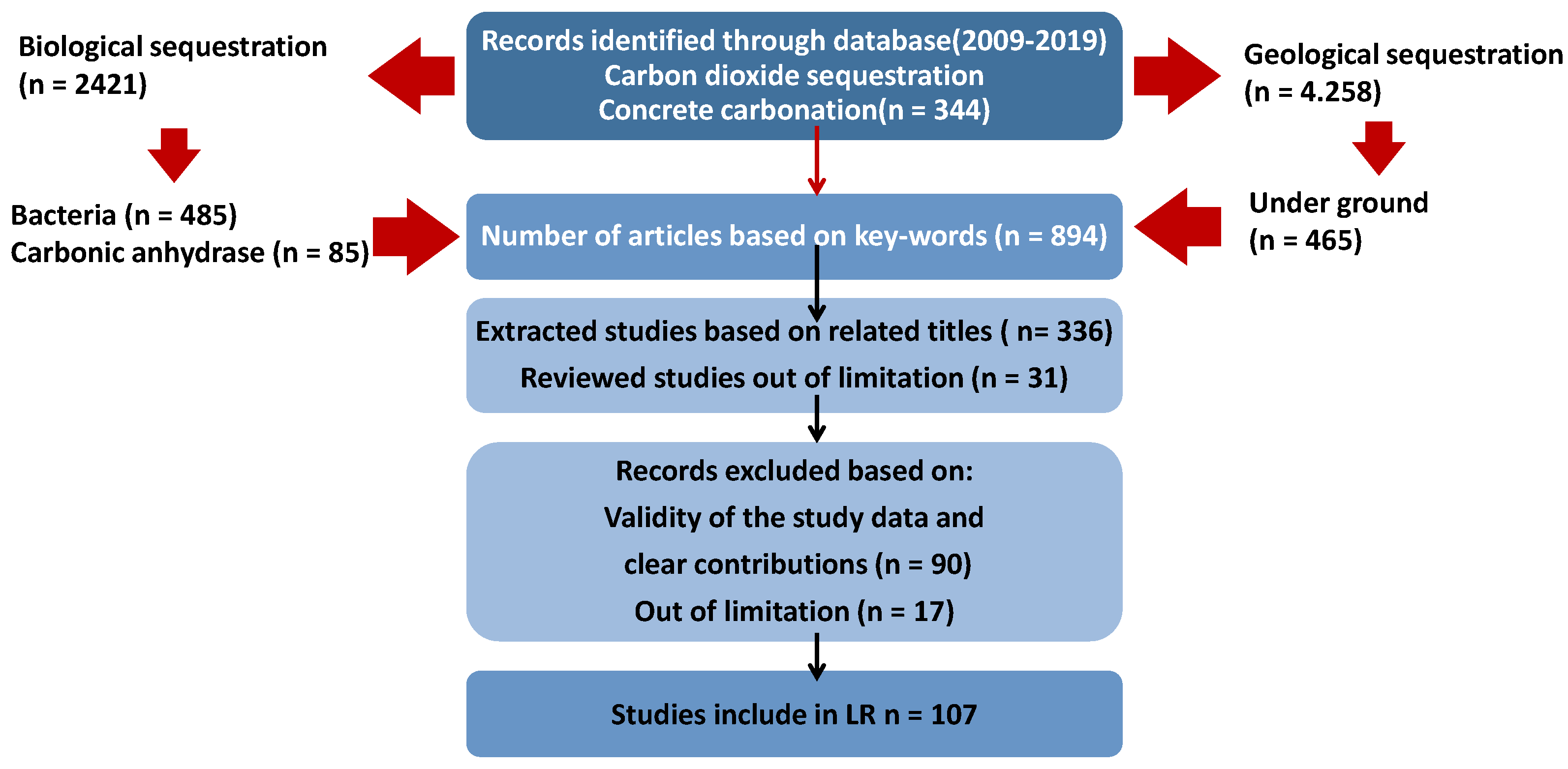
Figure 1. Steps of the review protocol.
Symmetry 14 02615 g001
Figure 2. Innovative concepts in CO2 capture and their cost reduction benefits versus their remaining development needs/time to commercialization [18,22,23]. (Reprinted/adapted with permission from Ref. [15]. Copyright © 2010 WILEY-VCH Verlag GmbH & Co. KGaA, Weinheim, Germany).
Symmetry 14 02615 g002
Figure 3. Materials for CO2 capture in the context of post combustion, precombustion, and oxyfuel processes [18]. (Reprinted/adapted with permission from Ref. [18]. Copyright © 2011 Elsevier Ltd., Amsterdam, the Netherlands. All rights reserved).
Symmetry 14 02615 g003
Figure 4. CO2 emissions system diagram for production of 1 m3 concrete [26]. (Reprinted/adapted with permission from Ref. [25]. Copyright © 1998 Elsevier Science Ltd., Amsterdam, the Netherlands. All rights reserved).
Symmetry 14 02615 g004
Figure 5. Summary of CO2-e for Grade 40 concrete mixtures with OPC and geopolymer binders [26]. (Reprinted/adapted with permission from Ref. [25]. Copyright © 2013 Elsevier Ltd., Amsterdam, the Netherlands. All rights reserved).
Symmetry 14 02615 g005
Figure 6. Factors affecting the carbonation process in concrete [1].
Symmetry 14 02615 g006
Figure 7. Schematics of overall recycling process. (Reprinted/adapted with permission from Ref. [41]. Copyright © 2016, Springer Japan).
Symmetry 14 02615 g007
Table 1. Temperature ranges in various studies (°C).
Ca(OH)2 TGA Decomposition CaCO3 TGA Decomposition Aragonite–Calcite Conversion Vaterite–Calcite Conversion Author
425–550 550–950 Chang and Chen [52]
460 Papadakis et al. [53]
400–500 600–800 Papadakis et al. [54]
300–500 800-1000 unknown/chlorides Huntzinger [55]
>500 Huijgen et al. [56]—slag
450–650 Taylor et al. [57]
464(DTA) 850–950 calcite Ramachandran et al. [58]
600–750 poorly crystallinedls20 well crystallized Cole and Kroone [59]
827–927 calcite ~460 ~350–400 Stern [60]
Table 2. Carbon adsorption of different materials.
MaterialCarbon AdsorptionMethodAuthor
Activated carbonsThe superior CO2 adsorption at 1 bar equal to 5.67 and 9.05 mmol/g, for 298 and 273 K, respectively.The isosteric heat of adsorption calculated on the basis of the Clausius–Clapeyron equation and Sips model Serafin et al., 2019
[72]
ZeolitesAt 30 degrees, zeolite-Y (designated as Z-Y-3, silica to alumina ratio of 2.25) sample exhibited maximum adsorption capacity, and the obtained values were around 114 and 190 mg CO2/g sorbent under atmospheric and 5 bar pressureCO2 capture capacity of the sorbents was examined at various temperatures and pressures employing a fixed-bed flow reactor and simulated flue gas. Murge et al., 2019
[73]
Silica gelThe sorbent synthesized with Li2CO3 and the BFS-derived silica gel at the Li/Si molar ratio of 4 (Li2CO3-BFS-4) possesses the best CO2 uptake performance with a sorption capacity of 0.329 g CO2/g, sorbent within 20 min. Liu et al., 2019
[74]
Metal–organic frameworksThe metal–organic frameworks (MOFs) are proving to be effective adsorbent material for CO2 capture due to their microporous structure. Younas et al., 2020
[75]
Polyethylenimine The utility of polyethylenimine (PEI)-implanted MIL-101 for dilute CO2 capture; adsorption capacity of 1.0 mmol/gat 400 ppm.Temperature Vacuum Swing AdsorptionDarunte et al.
[76]
Table 3. Biochar materials and related studies.
Biochar MaterialsStudiesAuthor
Agricultural wasterice strawIn the presence of pure CO2 gas, biochar had 2.6 wt% adsorption capacityC.K.C. Cabriga et al. [88]
corn stalksIt has been found that the biochar made from corn straw at 25 °C and 1 bar absorbs 4.51 mmol of CO2 per gramY.L. Zhou et al. [89]
sugarcane bagasseAccording to the studies conducted on sugarcane bagasse biochar, it has the capacity to adsorb CO2 at a temperature of 25 °C of 0.75 mmol/gChristiano et al. [90]
coffee groundsWith 30 °C adsorption temperature and a 30% CO2 concentration, coffee bagasse biochar could adsorb 2.8 mmol/g of CO2 at 600 °C pyrolysisAlivia Mukherjee et al. [91]
Wood wastepalm husk celluloseAs a result of maintaining 3.3 mmol/g of carbon dioxide adsorption at 25 °C and 1 bar, it is clear that good carbon capture is possibleGuo et al. [92]
date palm leavesWhen date palm leaves were pyrolyzed to make biochar, they adsorb the maximum CO2 of 0.25 mol/kgSalemet al. [93]
palm kernel shellsAt room temperature and standard atmospheric pressure, Promraksa et al. obtained a CO2 capture rate of 0.46 mmol/g using biochar produced from palm kernel shellsPromraksa et al. [94]
bambooIn their study, Waralee et al. used bamboo as the raw material for producing biochar, which absorbed 2.52 mmol/g of CO2 at 25 °C and a pressure of 1 bar.Waralee et al. [95]
Domestic garbage wastepine wood biocharBiochar produced at 550 °C absorbed CO2 at a rate of 1.66 mmol/g.Igalavithan et al. [96]
paper mill sludge biocharAt 25 °C and 1 bar, 0.2 mmol/g of biochar produced from paper mill sludge was measured at 600 °C.Igalavithan et al. [97]
biochar made from 70% wood chips and 30% chicken manureA combination biochar made from 70% wood chips and 30% chicken manure displayed 1.75 mmol/g CO2 adsorption capacityP.D. Dissanayake et al. [98]
pure wood chip biocharPure wood chip biochar had an adsorption capacity of 1.48 mmol/g at 30 °C and 1 bar of pressure
Publisher’s Note: MDPI stays neutral with regard to jurisdictional claims in published maps and institutional affiliations.