
Load Frequency Controller Design Based on the Direct Synthesis Approach Using a 2DoF-IMC Scheme for a Multi-Area Power System


Abstract
:1. Introduction
- Enhanced load-frequency regulation has been obtained by using the 2DoF-IMC control scheme.
- The controllers have been designed for the higher-order system without reduction of the system model.
- Proposed method has been tested for various cases of single-area power systems, two-area power systems and extended to the four-area power system.
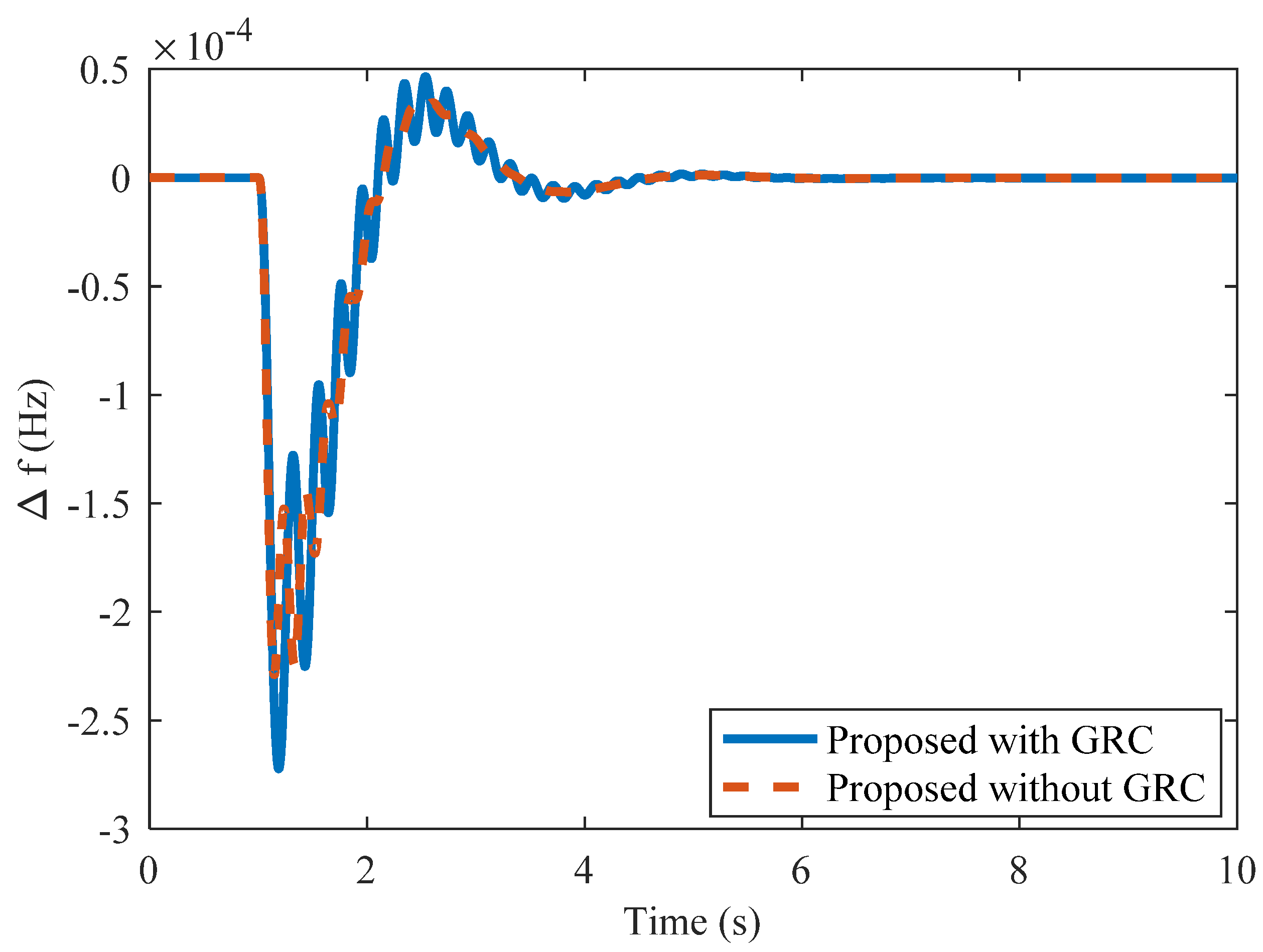
- The effect of GRC is incorporated into SAPSs to investigate the robustness of the proposed method.
- To analyze the robustness of the proposed controller, ±50% uncertainty in the system parameter and different step loading pattern is considered in the LFC system.
2. Description of Control Structure and Problem Formulation of LFC
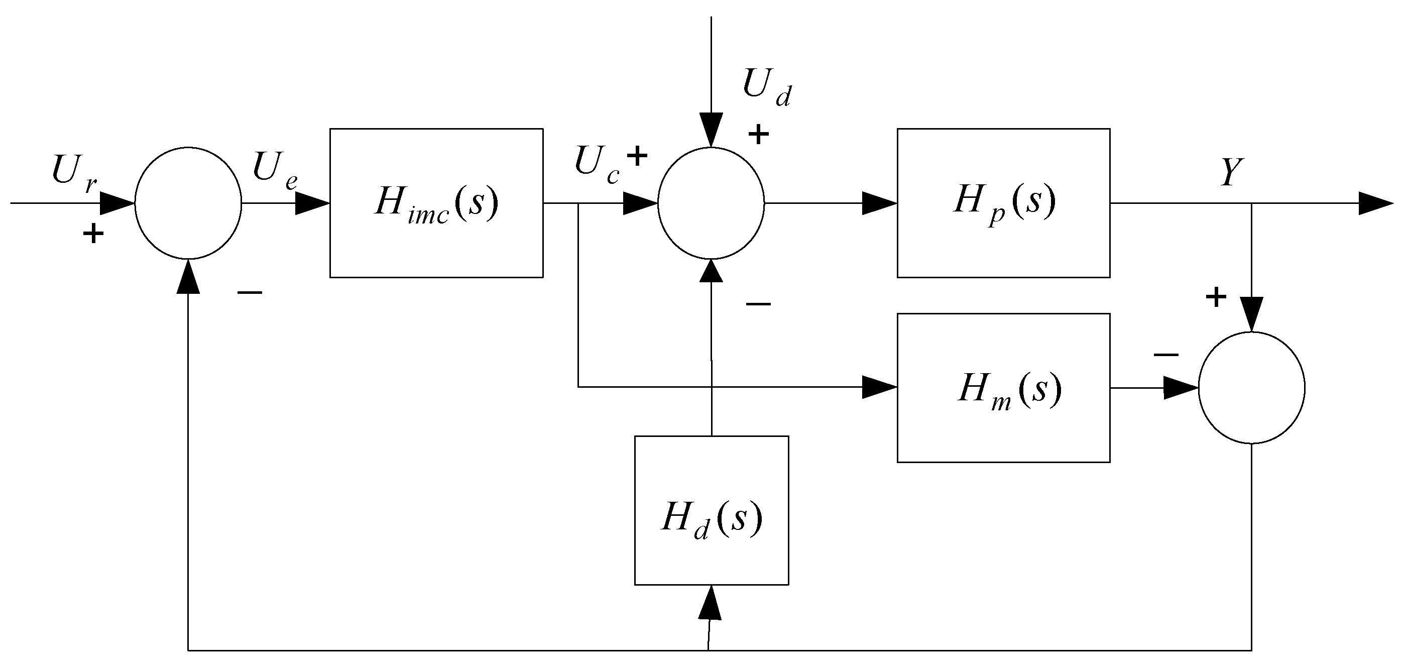
2.1. Brief Description of IMC and 2DoF-IMC Control Structure
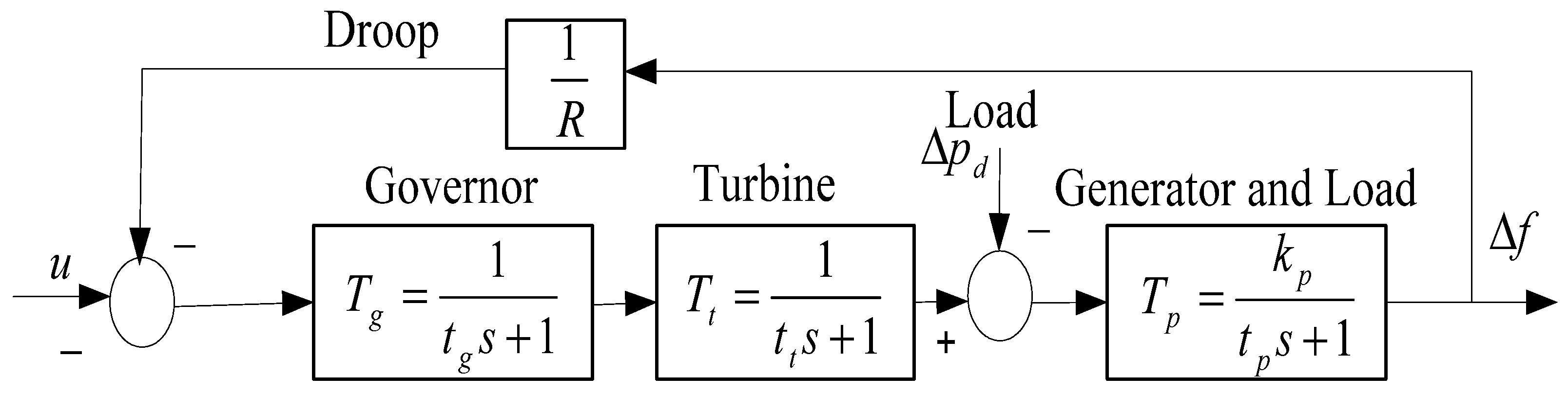
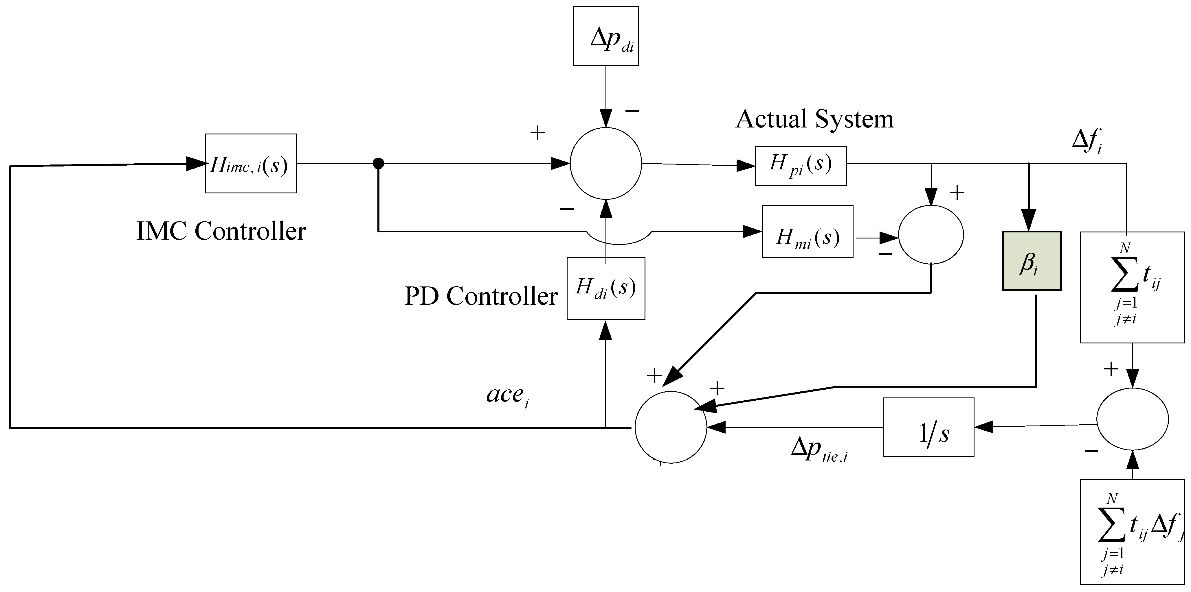
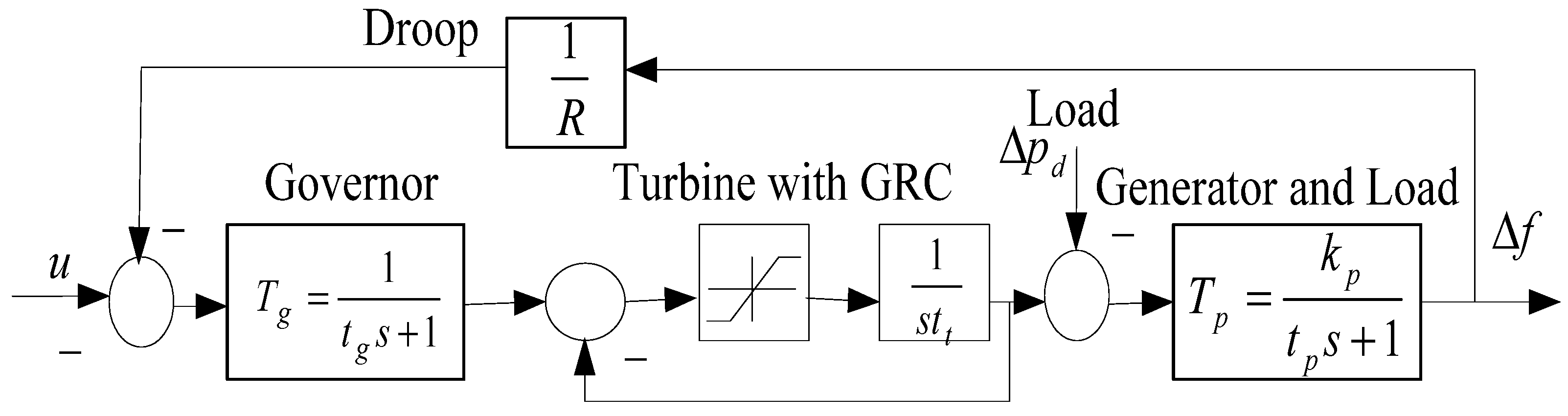
2.2. Modeling of Single- as Well as Multi-Area Power Systems
3. Controller Design Scheme
4. Results and Discussion
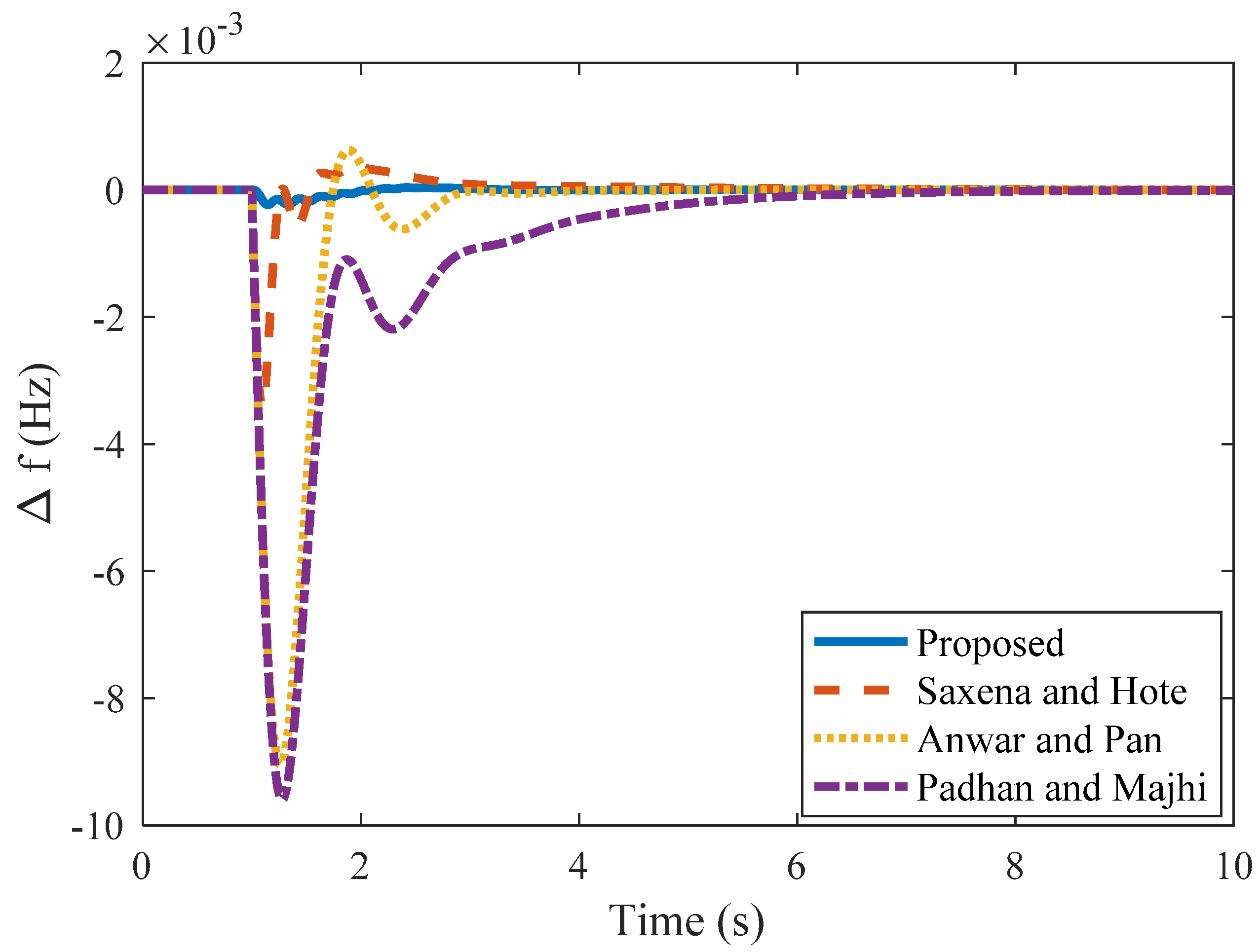
4.1. Case 1
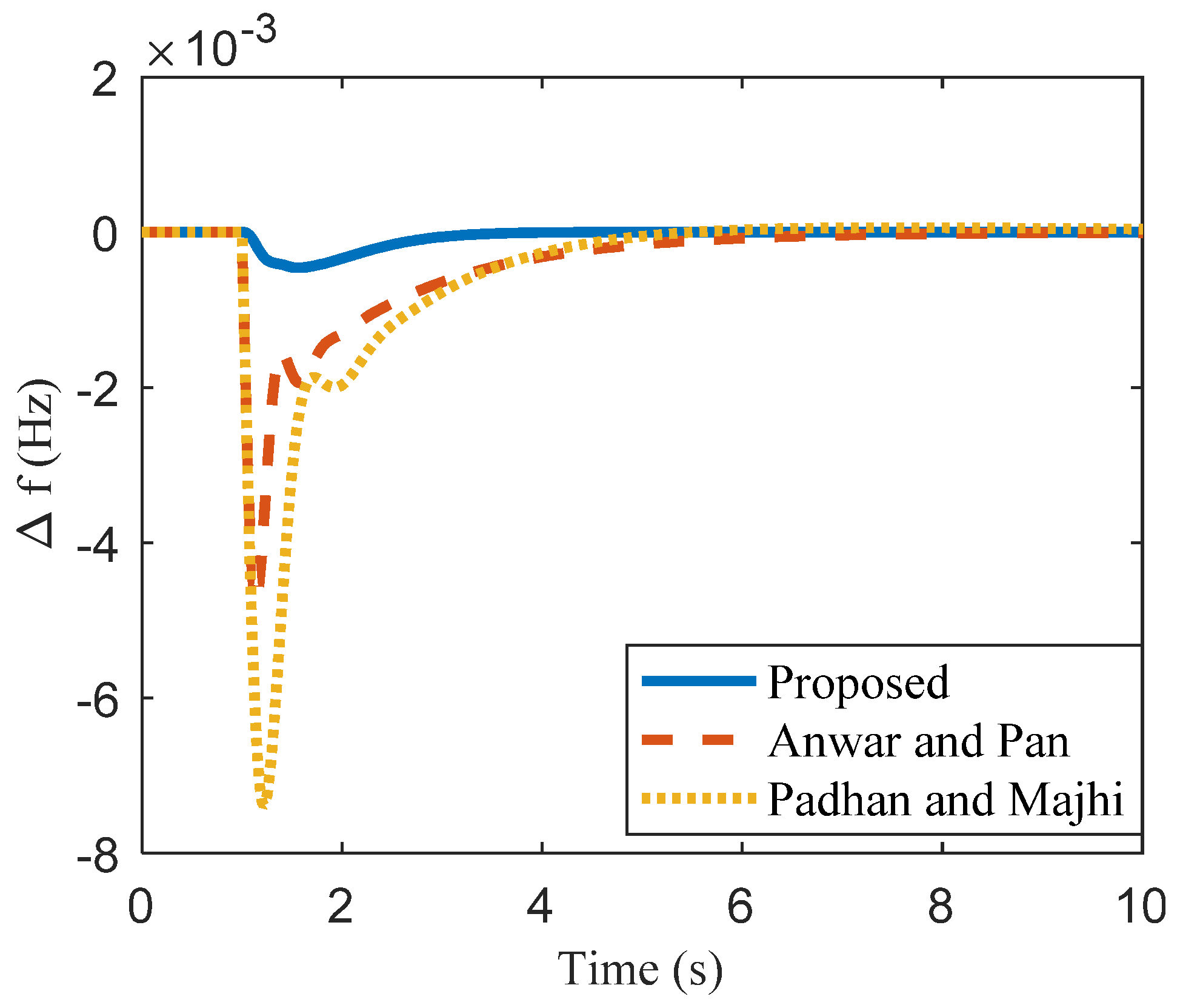
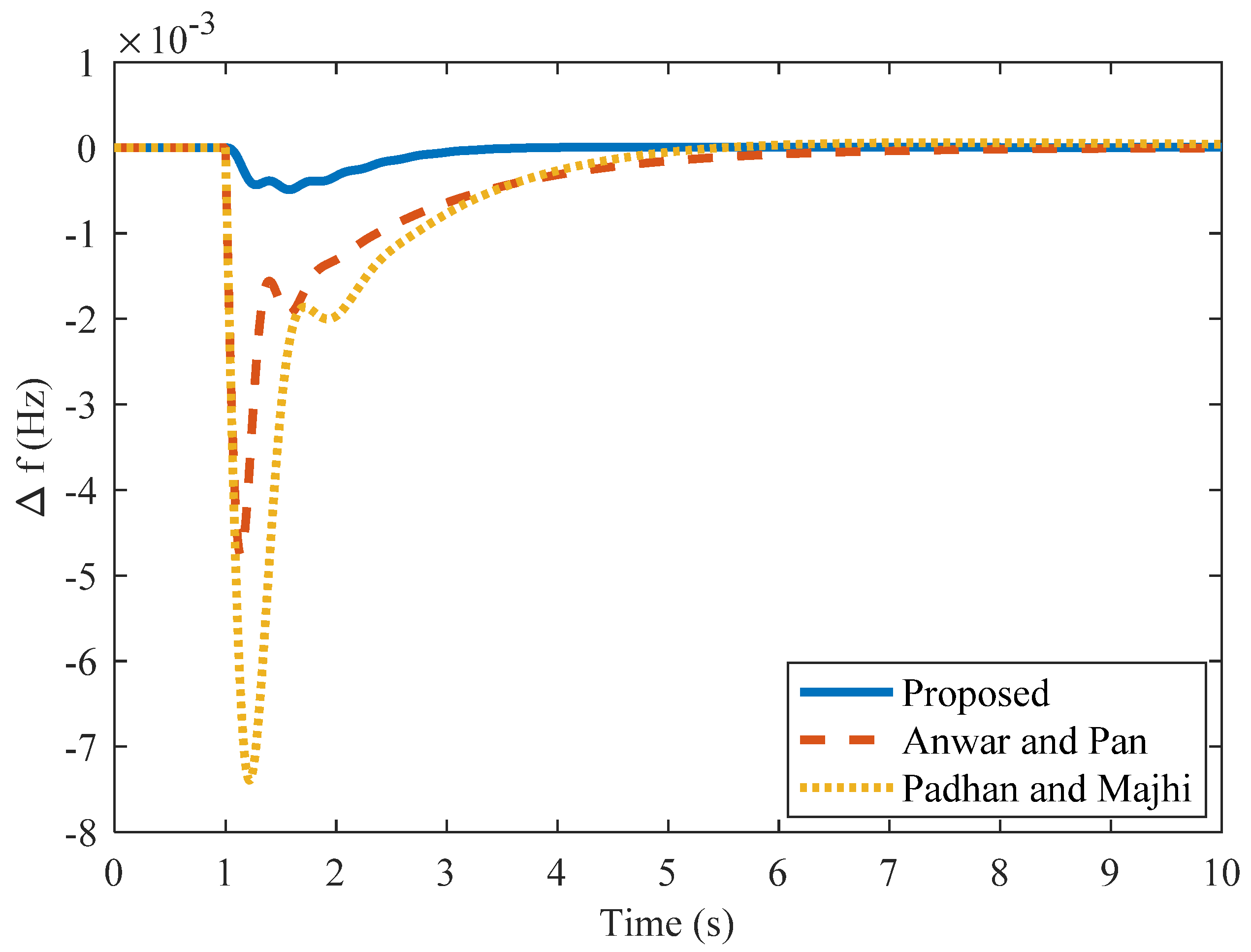
4.2. Case 2
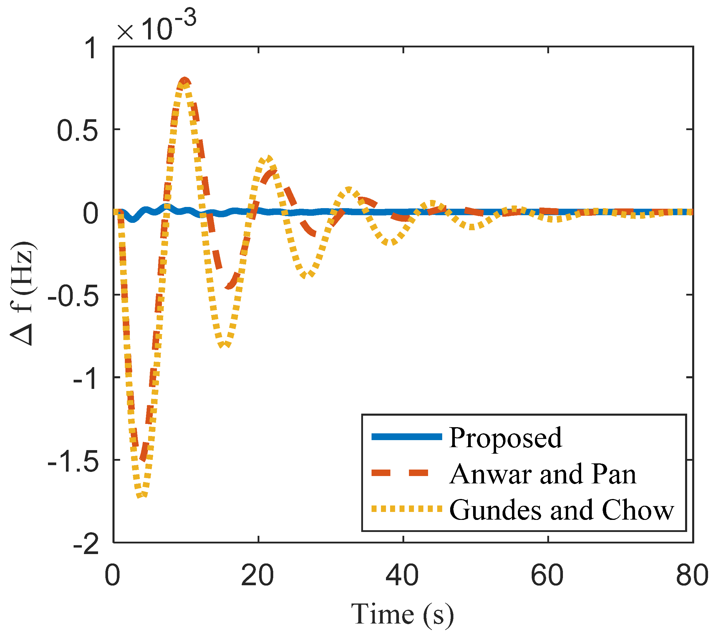
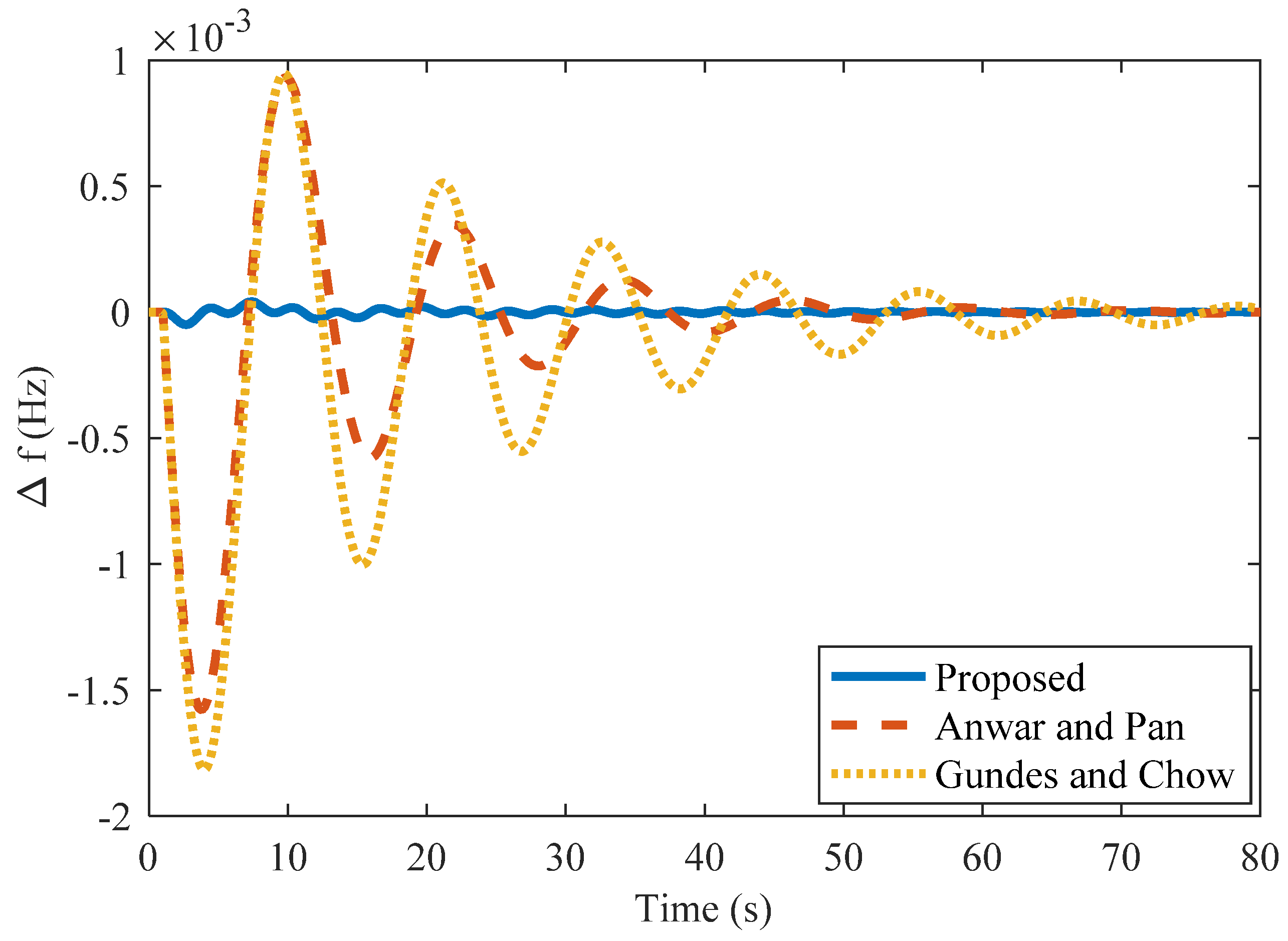
4.3. Case 3
4.4. Case 4: Single Area Non-Reheat Thermal Power System with GRC
4.5. Case 5
4.6. Case 5a: 10% Step Load in Area 1 and Zero Percent in Area 2
4.7. Case 5b: 10% Step Load in Area 2 and Zero Percent in Area 1
4.8. Case 5c: 10% Step Load in Both Areas
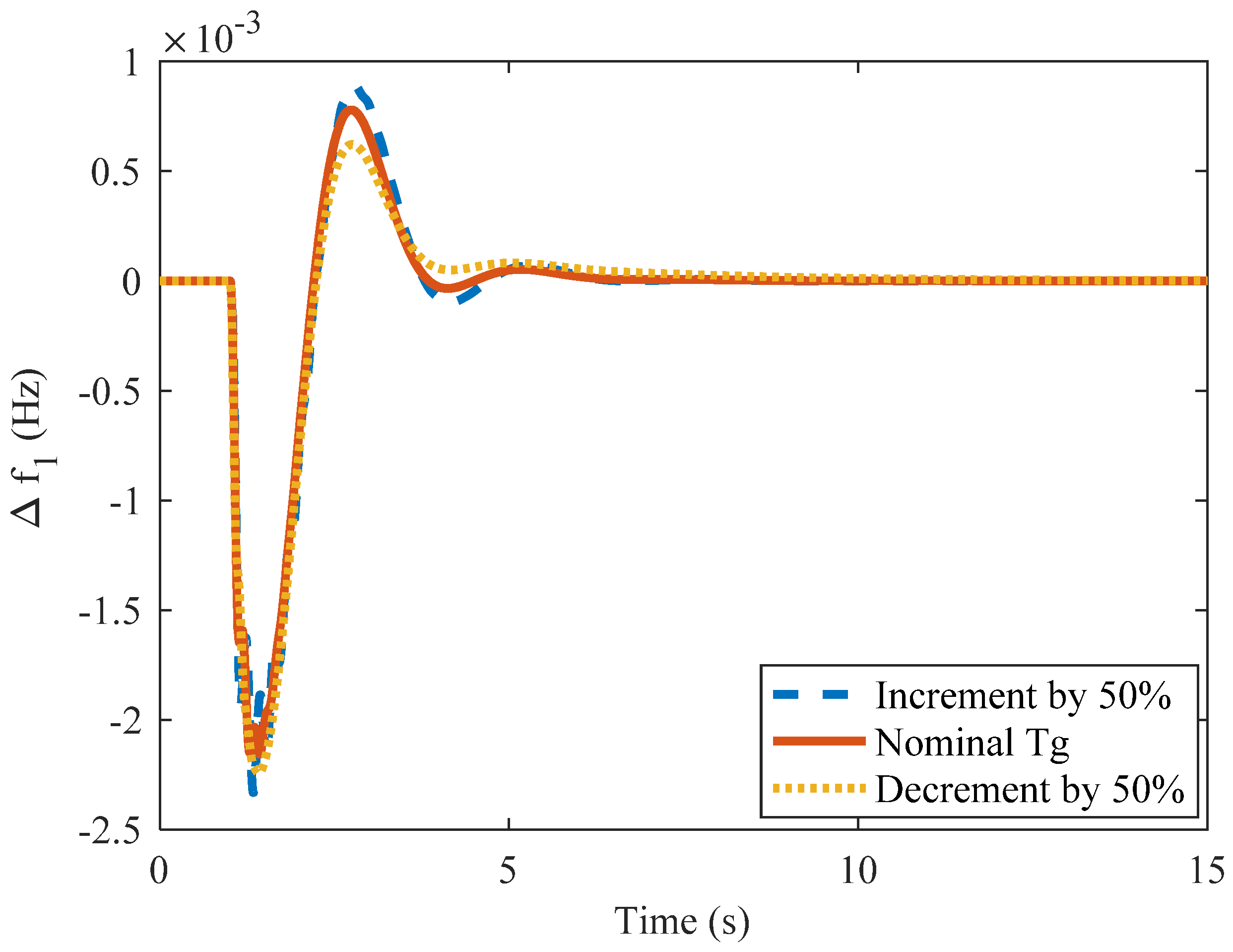
4.9. Case 5d: 50% Change in tg
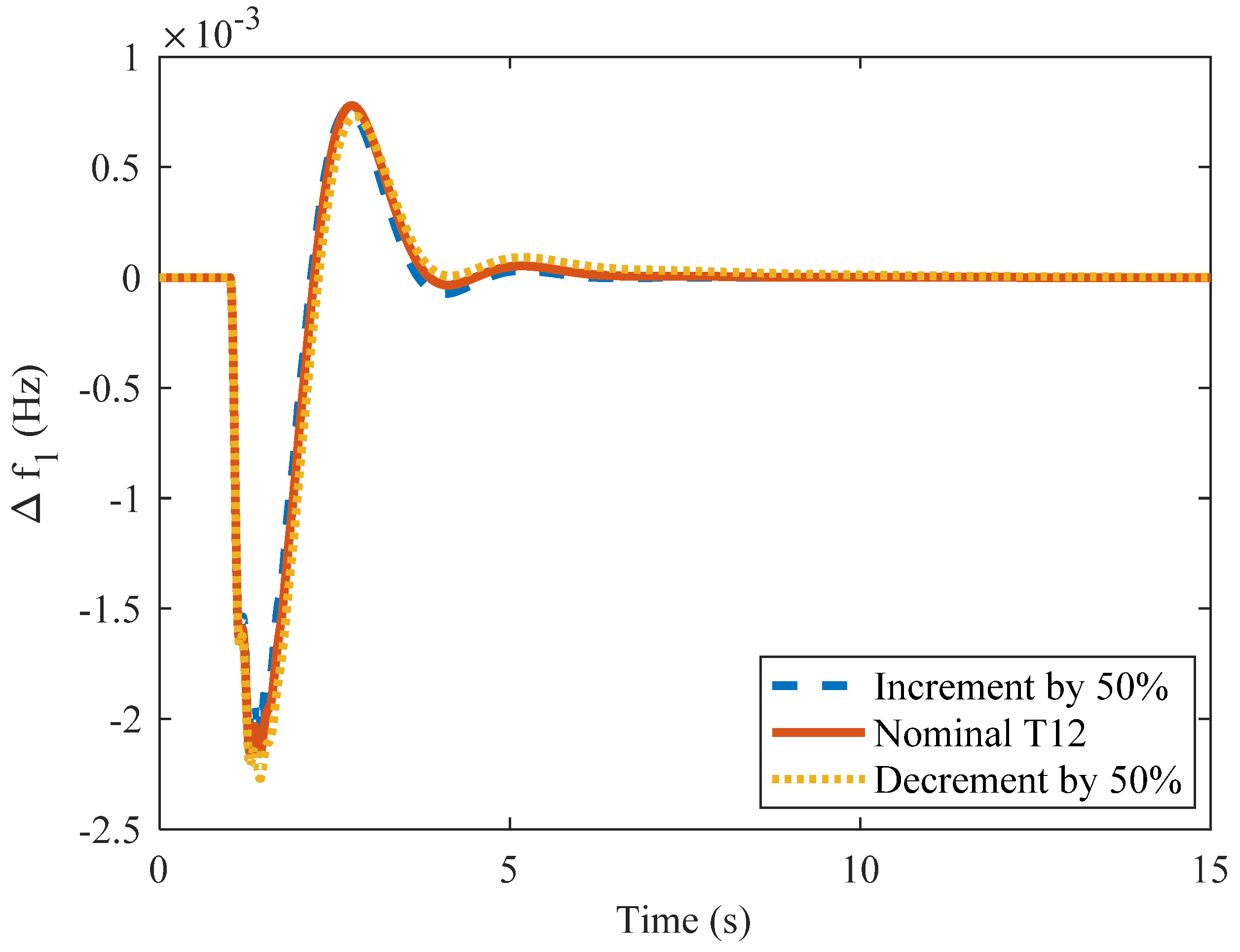
4.10. Case 5e: 50% Change in Tt
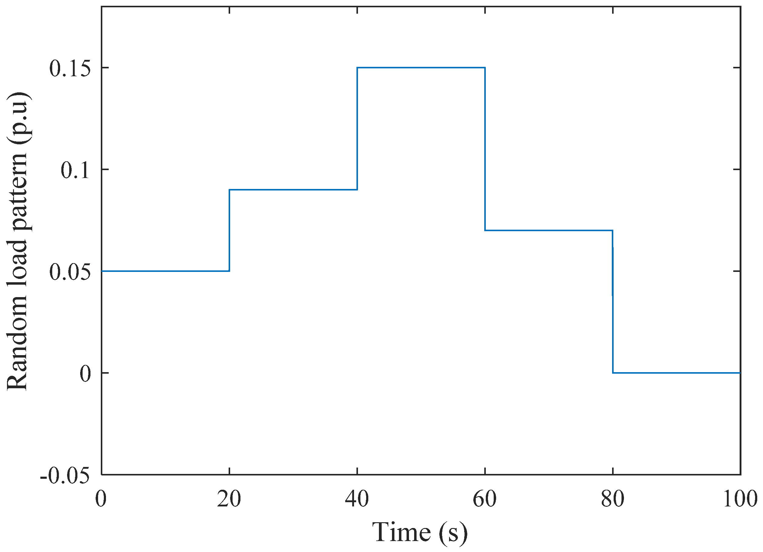
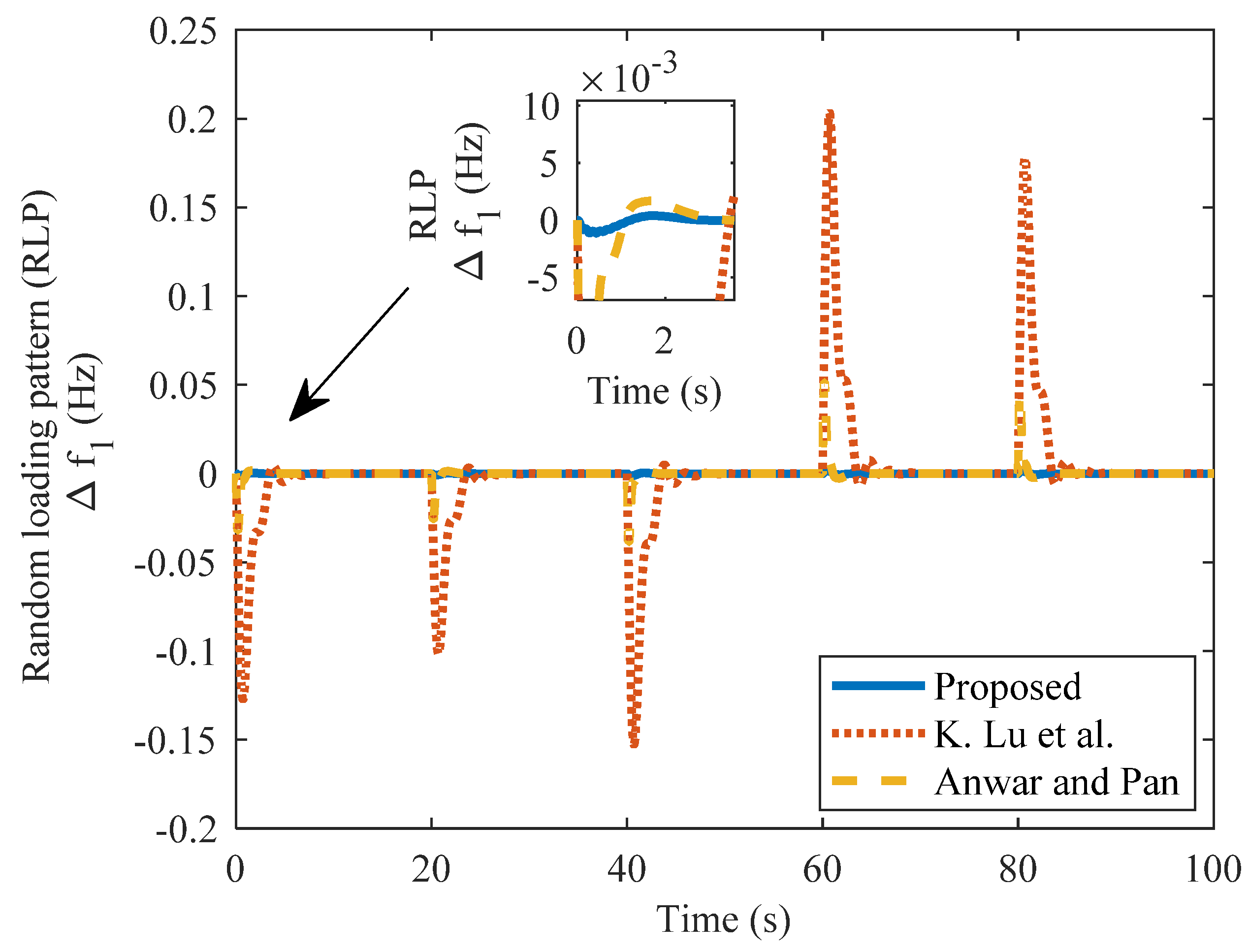
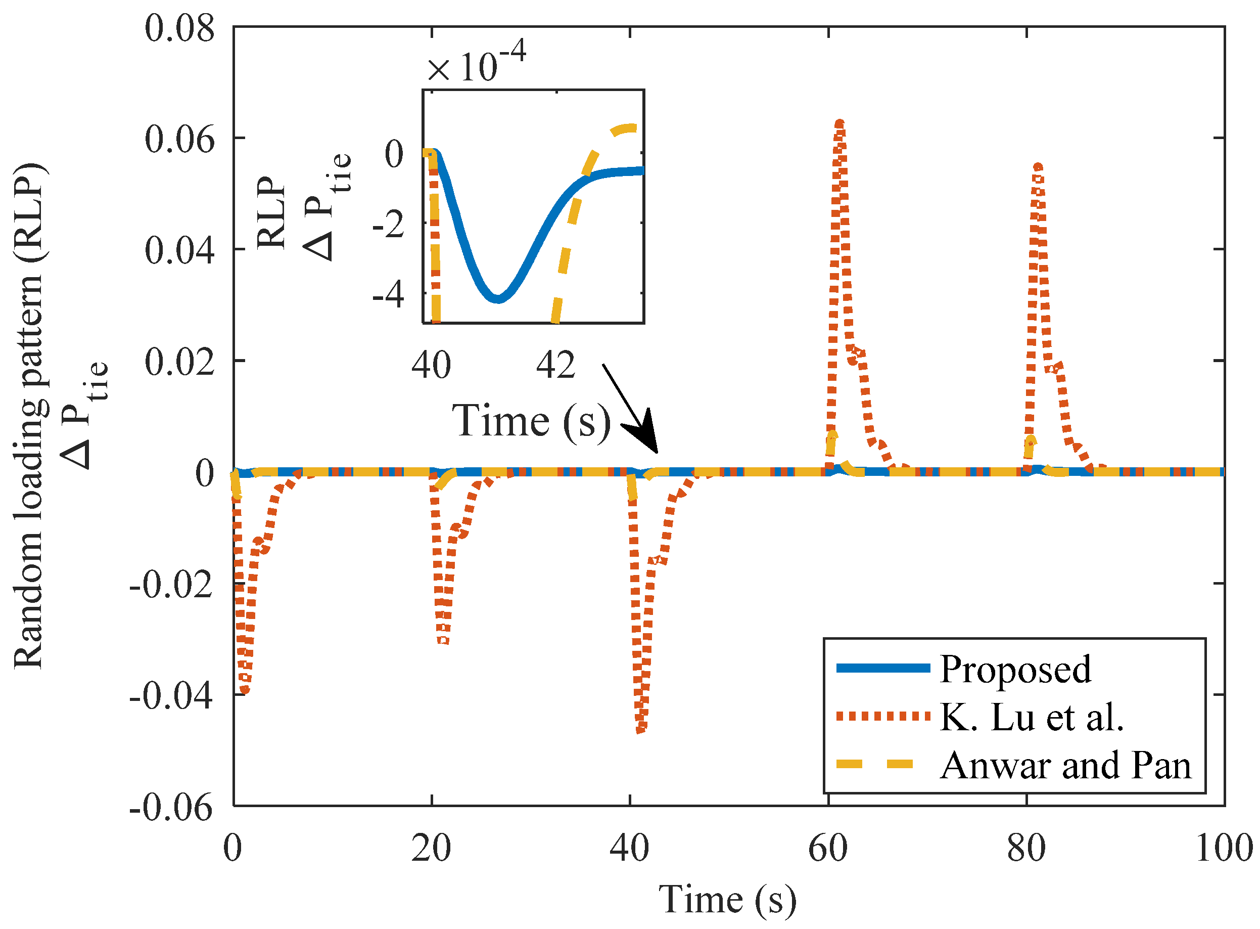
4.11. Case 5f: Random Loading in the TAPS
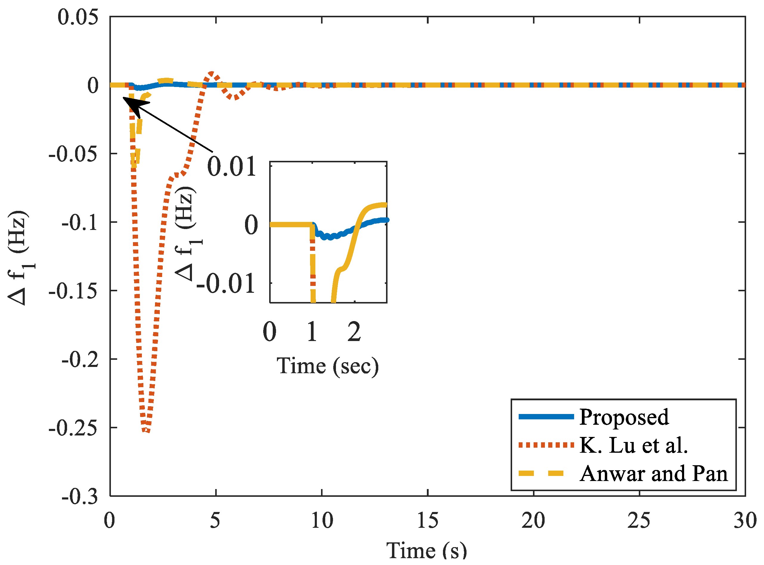
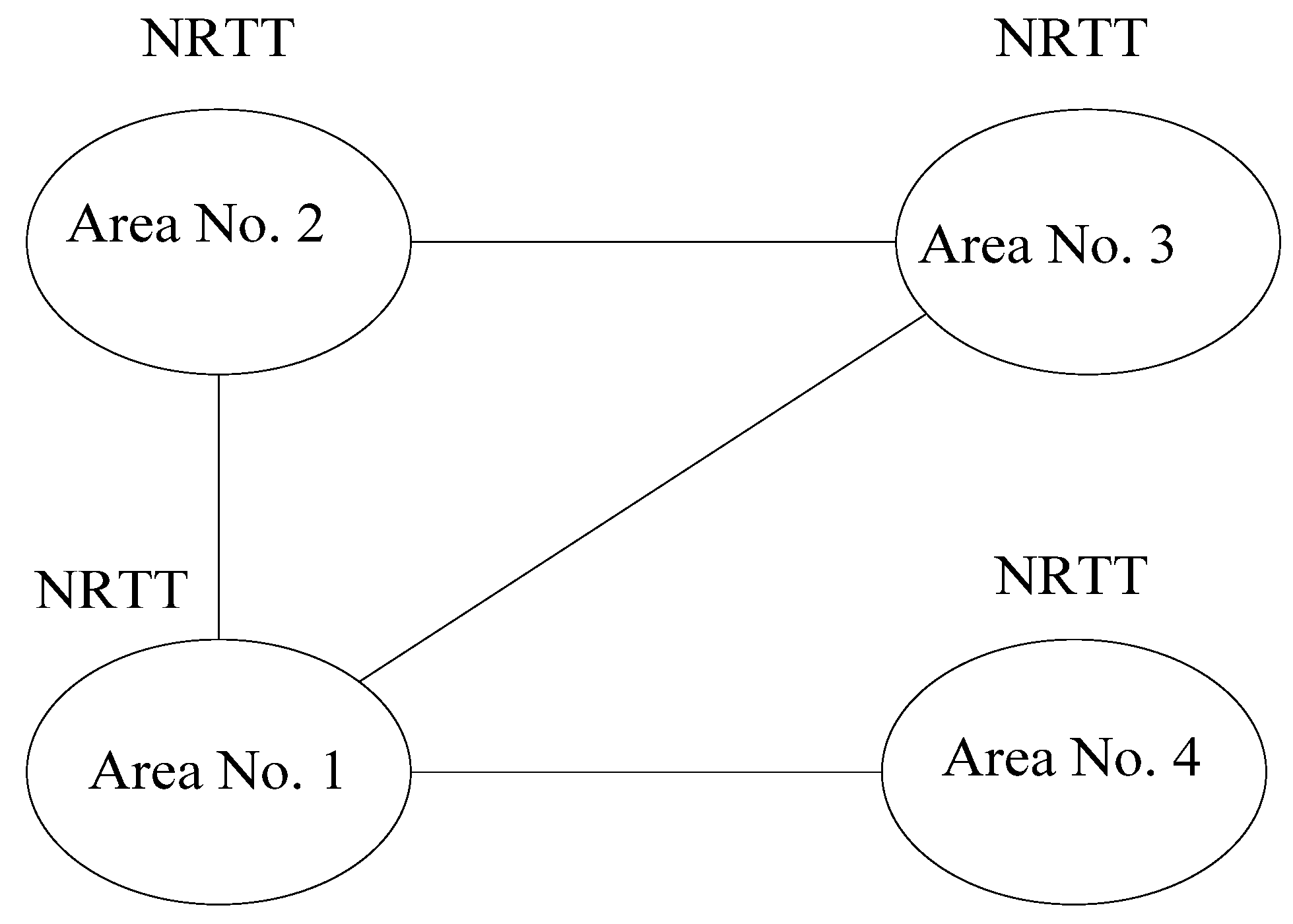
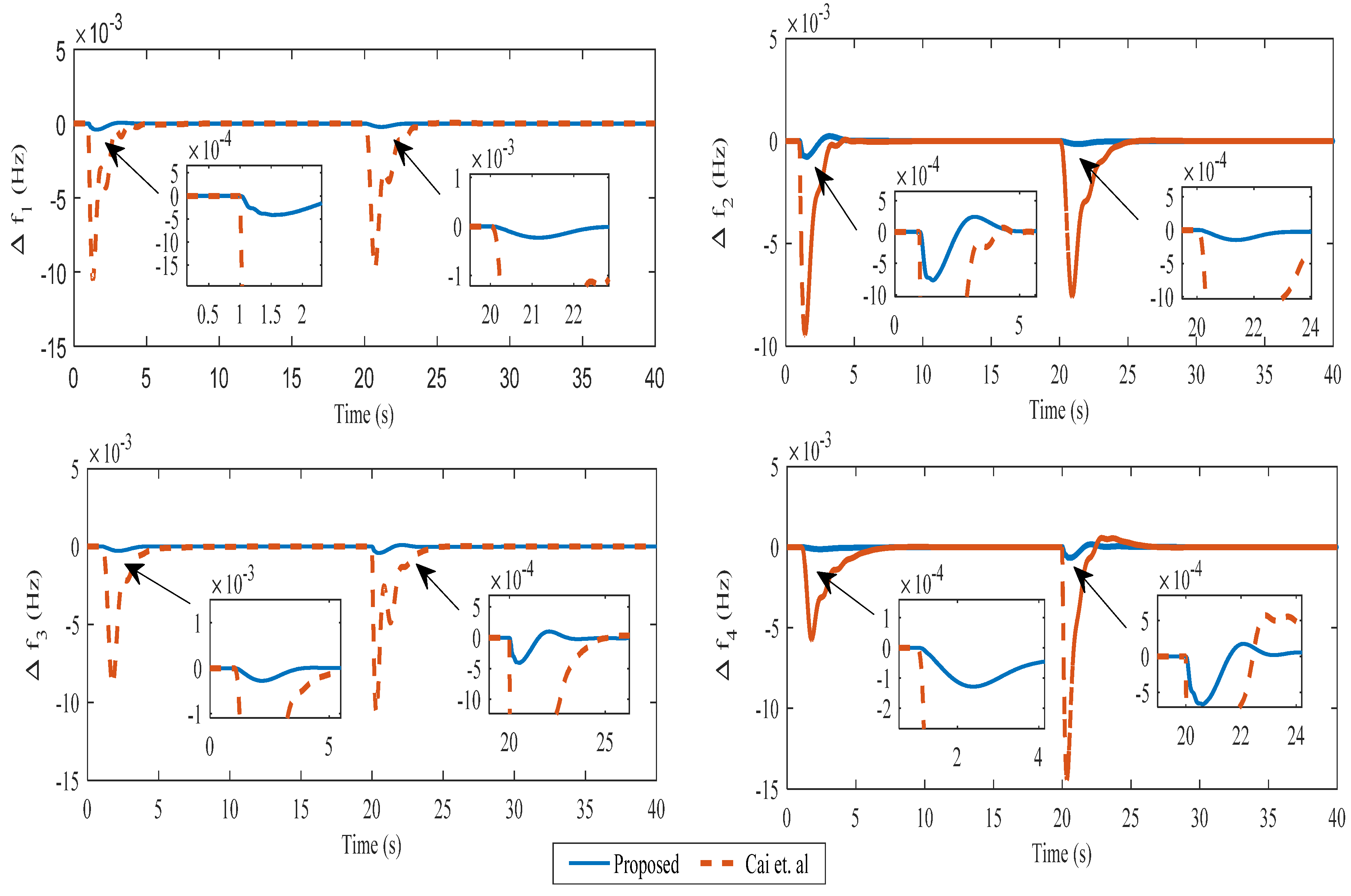
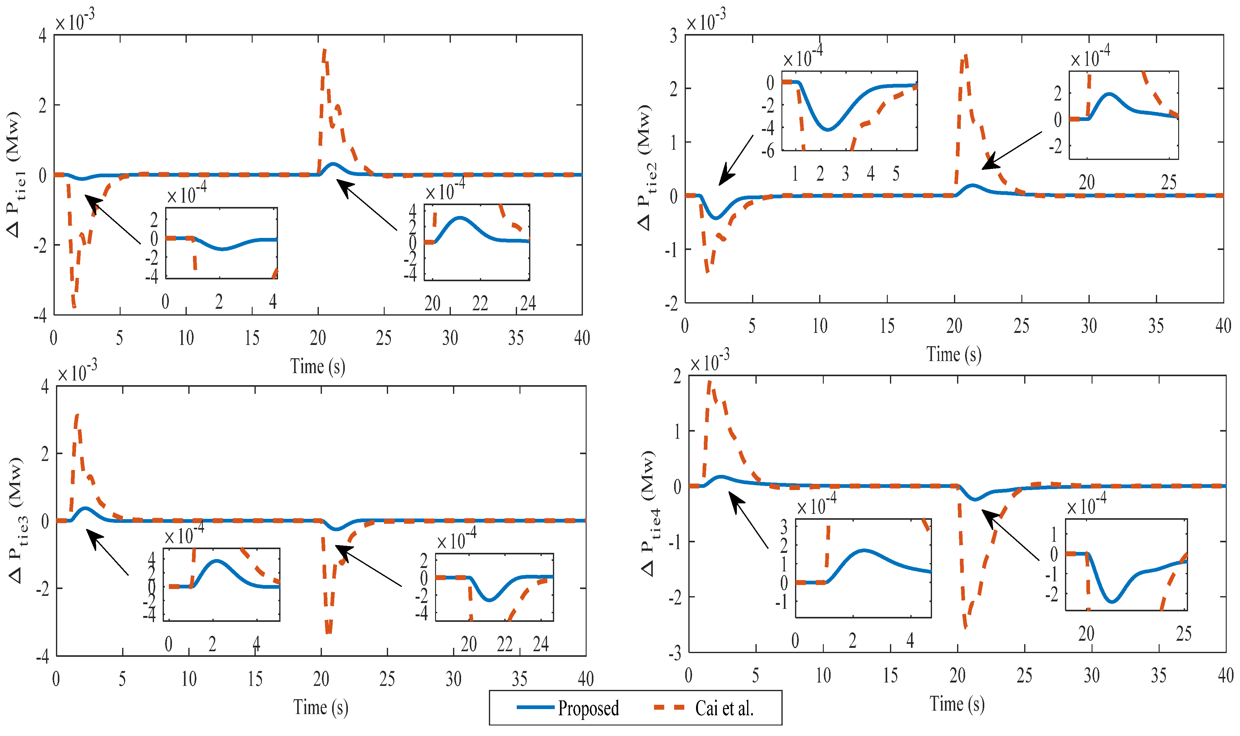
4.12. Case 6
5. Conclusions
Author Contributions
Funding
Data Availability Statement
Conflicts of Interest
Abbreviations
| 2DoF-IMC | Two-degree of freedom internal model control |
| IMC | Internal model control |
| DS | Direct synthesis |
| PD | Proportional–derivative |
| LFC | Load frequency control |
| GRC | Generation rate constraint |
| SAPS | Single area power system |
| MAPS | Multi-area power system |
| PID | Proportional–integral–derivative |
| TAPS | Two-area power system |
| FAPS | Four-area power system |
| PID + DD | PID double derivative |
| ACE | Area control error |
| ISE | Integral of square error |
| US | Undershoot |
| LDTF | Load disturbance transfer function |
| NRTT | Non-reheated thermal turbine |
Appendix A. System Parameters
References
- Kundur, P. Power System Stability and Control; McGraw-Hill: New-Delhi, India, 1994. [Google Scholar]
- Pappachen, A.; Fathima, A.P. Critical research areas on load frequency control issues in a deregulated power system: A state-of-the-art-of-review. Renew. Sustain. Energy Rev. 2017, 72, 166–177. [Google Scholar] [CrossRef]
- Shankar, R.; Pradhan, S.R.; Chatterjee, K.; Mandal, R. A comprehensive state of the art literature survey on LFC mechanism for power system. Renew. Sustain. Energy Rev. 2017, 76, 1185–1207. [Google Scholar] [CrossRef]
- Tan, W. Tuning of PID load frequency controller for power systems. Energy Convers. Manag. 2009, 50, 1465–1472. [Google Scholar] [CrossRef]
- Tan, W. Unified tuning of PID load frequency controller for power systems via IMC. IEEE Trans. Power Syst. 2010, 25, 341–350. [Google Scholar] [CrossRef]
- Tan, W. Decentralized load frequency controller analysis and tuning for multi-area power systems. Energy Convers. Manag. 2011, 52, 2015–2023. [Google Scholar] [CrossRef]
- Saxena, S.; Hote, Y.V. Load frequency control in power systems via internal model control scheme and model-order reduction. IEEE Trans. Power Syst. 2013, 28, 2749–2757. [Google Scholar] [CrossRef]
- Saxena, S.; Hote, Y.V. Stabilization of perturbed system via IMC: An application to load frequency control. Control Eng. Pract. 2017, 64, 61–73. [Google Scholar] [CrossRef]
- Saxena, S. Load frequency control strategy via fractional-order controller and reduced-order modeling. Int. J. Electr. Power Energy Syst. 2018, 104, 603–614. [Google Scholar] [CrossRef]
- Singh, J.; Chattterjee, K.; Vishwakarma, C.B. Two degree of freedom internal model control-PID design for LFC of power systems via logarithmic approximations. ISA Trans. 2018, 72, 185–196. [Google Scholar] [CrossRef] [PubMed]
- Raju, M.; Saikia, L.C.; Sinha, N. Automatic generation control of a multi-area system using ant lion optimizer algorithm based PID plus second order derivative controller. Electr. Power Energy Syst. 2016, 80, 52–63. [Google Scholar] [CrossRef]
- Guha, D.; Roy, P.K.; Banerjee, S. Multi-verse optimisation: A novel method for solution of load frequency control problem in power system. IET Gener. Transm. Distrib. 2017, 11, 3601–3611. [Google Scholar] [CrossRef]
- Padhan, D.G.; Majhi, S. A new control scheme for PID load frequency controller of single-area and multi-area power systems. ISA Trans. 2013, 52, 242–251. [Google Scholar] [CrossRef] [PubMed]
- Anwar, M.N.; Pan, S. A new PID load frequency controller design method in frequency domain through direct synthesis approach. Int. J. Electr. Power Energy Syst. 2015, 67, 560–569. [Google Scholar] [CrossRef]
- Siddiqui, M.A.; Anwar, M.N.; Laskar, S.H.; Mahboob, M.R. A unified approach to design controller in cascade control structure for unstable, integrating and stable processes. ISA Trans. 2021, 114, 331–346. [Google Scholar] [CrossRef] [PubMed]
- Gundes, A.N.; Chow, L. Controller synthesis for single-area and multi-area power systems with communication delays. In Proceedings of the 2013 American Control Conference (ACC), Washington, DC, USA, 17–19 June 2013; pp. 970–975. [Google Scholar] [CrossRef]
- Lu, K.; Zhou, W.; Zeng, G.; Zheng, Y. Constrained population extremal optimization-based robust load frequency control of multi-area interconnected power system. Int. J. Electr. Power Energy Syst. 2018, 105, 249–271. [Google Scholar] [CrossRef]
- Cai, L.; He, Z.; Member, S.; Hu, H. A New Load Frequency Control Method of Multi-Area Power System via the Viewpoints of Port-Hamiltonian System and Cascade System. IEEE Trans. Power Syst. 2016, 32, 1689–1700. [Google Scholar] [CrossRef]
- Kumar, A.; Anwar, N. Parallel control structure scheme for load frequency controller design using direct synthesis aproach. Int. J. Electr. Comput. Eng. 2020, 10, 47–60. [Google Scholar] [CrossRef]
- Huba, M.; Vrancic, D. Performance Portrait Method: An Intelligent PID Controller Design Based on a Database of Relevant Systems Behaviors. Sensors 2022, 22, 3753. [Google Scholar] [CrossRef] [PubMed]
- Huba, M.; Vrancic, D. Tuning of PID Control for the Double Integrator Plus Dead Time Model by Modified Real Dominant Pole and Performance Portrait Methods. Mathematics 2022, 10, 971. [Google Scholar] [CrossRef]


| Method | kc | ki | Kd | Nominal Plant | Perturbed Plant | |||||
|---|---|---|---|---|---|---|---|---|---|---|
| Under-Shoot (US) (×10−3) | % Improvement in Terms of US Value w.r.t Padhan and Majhi | ts | ISE (×10−5) | Peak Value (×10−3) | ts | ISE (×10−5) | ||||
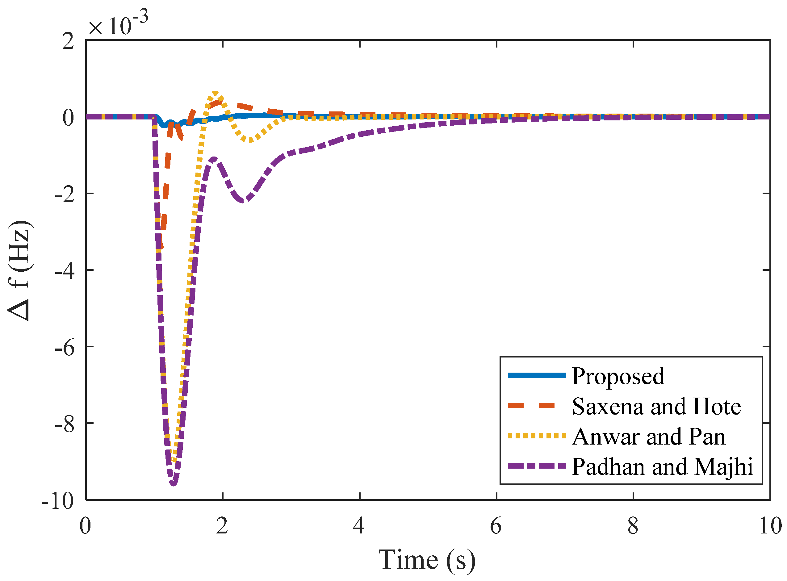
| Proposed PD | 44.724 | - | 4.17 | −0.23 | 97.6 | 1.92 | 0.19 | −0.22 | 1.98 | 0.19 |
| Saxena and Hote [8] | 66.96 | 171.6 | 15.91 | −3.4 | 64.6 | 6.1 | 0.14 | −3.4 | 5.1 | 0.14 |
| Anwar and Pan [14] | 1.52 | 2.50 | 0.27 | −9.02 | 6.04 | 2.87 | 3.5 | −9.02 | 2.87 | 3.6 |
| Padhan and Majhi [13] | 1.49 | 1.30 | 0.235 | −9.6 | 4.07 | 2.6 | −9.6 | 6.90 | 2.6 | |
| Method | kc | ki | Kd | Nominal Plant | Perturbed Plant | |||||
|---|---|---|---|---|---|---|---|---|---|---|
| Under-Shoot (US) (×10−3) | % Improvement in Terms of Peak Value w.r.t Tan Padhan and Majhi | ts | ISE (×10−6) | Peak Value (×10−3) | ts | IAE (×10−5) | ||||
| Proposed PD | 16.03 | - | 4.74 | −0.45 | 95.3 | 2.45 | 0.11 | −0.48 | 2.35 | 1.42 |
| Anwar and Pan [14] | 10.6 | 2.50 | 2.57 | −4.75 | 50.5 | 6.80 | 9.7 | −4.76 | 6.8 | 0.70 |
| Padhan and Majhi [13] | 6.16 | 1.93 | 1.16 | −9.6 | 11.8 | 1.39 | −7.4 | 11.8 | 1.95 | |
| Method | kc | ki | Kd | Nominal Plant | Perturbed Plant | |||||
|---|---|---|---|---|---|---|---|---|---|---|
| Under-Shoot (US) | % Improvement in Terms of Peak Value w.r.t Tan Gundes and Chow | ts | ISE (×10−6) | Peak Value (×10−3) | ts | IAE (×10−5) | ||||
| Proposed PD | 274.2 | - | 54.19 | −0.04 | 97.68 | 7.07 | 0.11 | −0.04 | 7.15 | 0.01 |
| Anwar and Pan [14] | 0.267 | 2.50 | 9.70 | −1.51 | 12.7 | 41.5 | 9.7 | −1.57 | 41.8 | 1.17 |
| Gundes and Chow [16] | 1.50 | 1.05 | 0.44 | −1.73 | 62.6 | 1.39 | −1.81 | 63 | 1.8 | |
| Method | Kp | Ki | Kd | Area 1 | Area 2 | Tie-Line Power | ||||
|---|---|---|---|---|---|---|---|---|---|---|
| %US (×10−2) | ts | ISE (×10−3) | %US (×10−2) | ts | % US (×10−3) | ts | ||||
| Proposed PD | 24.5 | - | 4.425 | −0.22 | 0 | 0.45 | −0.05 | 0 | 0.70 | 0 |
| Anwar and Pan [14] | 3.55 | 5.95 | 1.22 | −6.4 | 0.44 | 0.33 | −2.5 | 0.69 | −8.42 | 0.4 |
| Tan [4] | 1.569 | 2.397 | 0.525 | −25.4 | 3.14 | 33 | −0.22 | 4.26 | −0.078 | 3.64 |
Publisher’s Note: MDPI stays neutral with regard to jurisdictional claims in published maps and institutional affiliations. |
© 2022 by the authors. Licensee MDPI, Basel, Switzerland. This article is an open access article distributed under the terms and conditions of the Creative Commons Attribution (CC BY) license (https://creativecommons.org/licenses/by/4.0/).
Share and Cite
Kumar, A.; Anwar, M.N.; Huba, M. Load Frequency Controller Design Based on the Direct Synthesis Approach Using a 2DoF-IMC Scheme for a Multi-Area Power System. Symmetry 2022, 14, 1994. https://doi.org/10.3390/sym14101994
Kumar A, Anwar MN, Huba M. Load Frequency Controller Design Based on the Direct Synthesis Approach Using a 2DoF-IMC Scheme for a Multi-Area Power System. Symmetry. 2022; 14(10):1994. https://doi.org/10.3390/sym14101994
Chicago/Turabian StyleKumar, Anand, Md Nishat Anwar, and Mikulas Huba. 2022. "Load Frequency Controller Design Based on the Direct Synthesis Approach Using a 2DoF-IMC Scheme for a Multi-Area Power System" Symmetry 14, no. 10: 1994. https://doi.org/10.3390/sym14101994
APA StyleKumar, A., Anwar, M. N., & Huba, M. (2022). Load Frequency Controller Design Based on the Direct Synthesis Approach Using a 2DoF-IMC Scheme for a Multi-Area Power System. Symmetry, 14(10), 1994. https://doi.org/10.3390/sym14101994