Abstract
Multiple sets of spring, spring seat structures are uniformly arranged in circumferential short spring dual mass flywheel (DMF), which generally have a symmetrical structure. The internal springs and spring seats are constrained by the shape of the primary flywheel and the secondary flywheel. At different rotational speeds, the springs and spring seats have different centrifugal forces. To study the dynamic characteristics of the DMF including torque and stiffness with considering the influence of centrifugal force and friction, the discrete method is used to analyze the mechanical actions of the transmission parts in DMF. The torque action between the spring seat and the secondary flywheel is deduced. The dynamic characteristics of the DMF are obtained through analyzing and calculating. Due to the symmetry of the structure, the torque transmitted and the stiffness of the DMF also have specific symmetrical characteristics. Namely, at two relative rotational angles of the same magnitude and opposite direction, the magnitude of the transmitted torque is the same, the direction is opposite. The magnitude and direction of stiffness are the same. The influence of speed, friction coefficient, spring mass, and spring seat mass on the torque and stiffness characteristics are analyzed. Finally, the theoretical analysis is proved to be valid by the torque characteristics test of DMF.
1. Introduction
Torsional vibration of the powertrain, which is a common phenomenon in vehicles equipped with an internal combustion engine, is mainly due to the changing output torque of the engine and the crank-link mechanism inertial force. Torsional vibration of the vehicle powertrain will affect the reliability, durability, and comfort of the vehicle. To reduce torsional vibration, various kinds of torsional vibration dampers applied have arisen with the automobile industry development. The growing expectations related to driving comfort and the rapid development of powerful and high-torque engines in recent years make torsional vibration reduction more challenging. Dual mass flywheel (DMF), which is an efficient torsional vibration damper developed in the 1980s, has been continuously improved and widely adopted in vehicle transmission systems [1,2,3,4,5]. Academic researches on DMF mainly focused on the following aspects: (1) parameter design and optimization of spring damper and analysis of the influence of parameters on vibration reduction characteristics of DMF. Lü et al. [4,6,7,8,9] established the force model of the long arc spiral spring by the discrete method, and analyzed the torque characteristics and influencing factors under loading and unloading conditions. Huang et al. [10] deduced the stiffness calculation formula of the arc spiral spring in a DMF and completed the spring parameter calculation and structure design of two types of DMF with 2 springs and 6 springs. Lü et al. [11] developed the analytical expression of the nonlinear elastic characteristics and the calculation formula of the torsional stiffness of a circumferential short spring-type DMF. (2) Dynamic analysis modeling and dynamic characteristic analysis of DMF. He et al. [12] built a 9DOF analytical model of driveline torsional vibration system with DMF and analyzed the influence of the parameters of the DMF on driveline torsional vibration in the engine start-up process. Tang et al. [13] established a torsional vibration dynamic model of the hybrid powertrain with ADAMS software and explored the effect of a DMF on the torsional vibration. To study the vibration reduction performance of DMF in the transmission system, Chen et al. [14] established a 6DOF nonlinear analytical model and designed a comprehensive multi-condition simulation strategy. (3) The improving design for DMF’s structure. Shi et al. [15] given a new structure of damping spring components with nested arrangement inside and outside, which made the DMF stiffness change from single-stage to three-stage. Song et al. [16] added a compensation device in a DMF structure. It makes this DMF has a continuously variable stiffness, which can avoid the impact produced by the abrupt changes in stiffness. A DMF with a two-stage variable stiffness structure is proposed by Song et al. [17]. This DMF has low torque and stiffness at small relative rotational angles and high resistance torque and stiffness at large relative rotational angles. (4) Novel structure of DMF and its performance research. Li et al. [18] presented the design method of a DMF with radial spring and analyzed its inherent characteristics of torsional vibration. Zu et al. [19] designed a magnetorheological fluid DMF, and derived the damping torque characteristics, and developed the controller of the DMF. (5) Test analysis method and testbed development of DMF, as presented in [5,20,21,22].
Springs and spring seats, which are the main damping parts of the circumferential short spring DMF, are used to transmit torque and reduce vibration. The springs and spring seats inside the DMF are constrained by the shapes of the primary flywheel and the secondary flywheel. As we all know, rotating mechanical parts are subjected to centrifugal force. Especially at high rotational speed, large centrifugal force may cause the increase of vibration, noise, fitting clearance, stress, and deformation [23,24,25,26]. In this way, the operating accuracy and service life of the mechanical system will be reduced. The influence of centrifugal force on mechanical systems has always been widely concerned. Xu et al. [27] analyzed the influence of centrifugal force on the characteristics of stiffness and contact stress distribution of a spindle-holder taper joint. The results indicated that centrifugal force will cause serious non-uniform distribution of the stress, and the centrifugal force of the holder results in serious deviation of the holder. Tutuncu [23] determined stresses and deformations in rotating specially orthotropic circular plates caused by centrifugal forces. Feng et al. [28] found centrifugal force can reduce the effectiveness of the dynamic clamping force and make the high-speed cutting process dangerous. Abadian et al. [29] presented the effect of the centrifugal force on the electromechanical instability of U-shaped and double-sided sensors incorporating the size-dependency and the vdW force. Hashimoto et al. [30] found that centrifugal force can affect significantly the film pressure and load-carrying capacity of bearing. Liu et al. [31] investigated the comprehensive effects of centrifugal force on the dynamic characteristics of the planetary gear at high speeds.
Due to the constantly changing output torque of the engine, the rotational speed of the DMF equipped with this engine is also changing during working. In addition, we all know that when two objects contact and squeeze each other and have a relative motion or relative motion trend, they will produce friction on the contact surface. The centrifugal force of spring and spring seat at different speeds and friction will affect the interaction forces between spring, spring seat, primary flywheel, and secondary flywheel, thereby affecting the torque and stiffness of the DMF. The vibration reduction performance of DMF is directly determined by its stiffness. Therefore, when designing and analyzing DMF, the influences of friction and centrifugal force of spring and spring seats at different speeds need to be considered. In the current researches, the modeling and analysis of circumferential short spring DMF with considering both centrifugal force and friction are rarely seen. In this paper, the centrifugal force and friction are considered for the analysis of a circumferential short spring DMF. By analyzing the interaction forces between transmission parts in the DMF, the torque the DMF transmitted and stiffness is deduced. And the effects of speed, friction coefficient, spring mass, and spring seat mass on the characteristics of the DMF including torque and stiffness are illustrated. At last, the theoretical analysis is proved to be valid by torque characteristic tests.
The remainder of this paper is organized as follows. Section 2 presents the structure and parameters of the DMF. Section 3 addresses the modeling of force analysis between the transmission parts in the DMF with considering centrifugal force and friction in detail. Section 4 gives analysis results to illustrate the dynamic torque and stiffness characteristics of the DMF under different rotational speeds, friction coefficient, spring mass, and spring seat mass. This includes the torque characteristic tests of the DMF for proving the effectiveness of the theoretical analysis. Besides, the effects of rotational speed, friction coefficient, spring mass, and spring seat mass on the DMF are also discussed. Finally, Section 5 provides the conclusions.
2. DMF Structure and Parameters
As shown in Figure 1a, a circumferential short spring DMF is mainly composed of the primary flywheel, secondary flywheel, spring, spring seat, friction bearing block, and friction bearing inner ring. Multiple sets of spring, spring seat structures are uniformly arranged between the primary flywheel and secondary flywheel in the DMF, which generally have a symmetrical structure. After the primary flywheel which is connected to the engine crankshaft rotates, spring seats compress springs, and the spring seats at the other end push the secondary flywheel to rotate under the action of the spring force. Finally, the power and motion are transmitted to the other transmission parts of a vehicle behind.
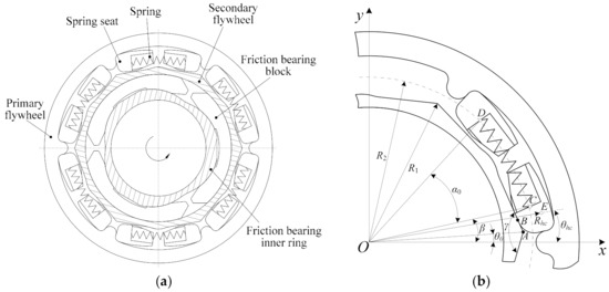
Figure 1.
Structure and main parameters of circumferential short spring DMF: (a) structure; (b) main parameters.
For the symmetry of the DMF structure, here, we analyze one set of spring and spring seat interactions with the primary flywheel and secondary flywheel, as shown in Figure 1b. Establish a rectangular coordinate system at the center of the DMF. Point A is the vertex of the secondary flywheel contour polygon outline. R1 is the maximum radial diameter of the secondary flywheel outline. R2 is the distance between point O and the support points C, D of spring seat to spring. α0 is the corresponding initial opening angle of the spring, and γ is the polygon vertex angle of the secondary flywheel outline. θ0 is the idle angle of the DMF. The initial polar coordinates point C are (R2, β). The initial polar coordinates of point E, which is the mass center of the spring seat, are (Rhc, θhc). β is the initial angle between line OC and the horizontal direction. After the primary flywheel has just turned the idle angle θ0, the spring seat contacts with the secondary flywheel. When the relative rotational angle is θ, the polar coordinates of point C are (R2, β + θ − θ0), and the polar coordinates of point E are (Rhc, θhc + θ − θ0).
3. Mechanical Analysis Model
3.1. Determination of Equivalent Force Position between the Secondary Flywheel and Spring Seat
After the secondary flywheel is in contact with the spring seat, the contact area in the plane is a line. With the variation of θ, the contact area can be approximately regarded as always remaining unchanged due to the small elastic deformation of the structure. Therefore, the length of the force arm of the normal force and the friction force remains unchanged. Suppose the contact length between the secondary flywheel and the spring seat is l, and the contact line is divided into λ segments. Thus the length of each segment is Δl = l/λ, and the polar coordinates of the initial contact position B1 are (RB1, θB1), as shown in Figure 2.
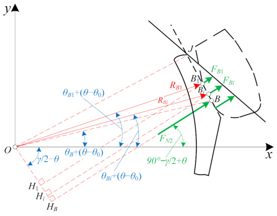
Figure 2.
Discrete forces in contact area.
At the beginning of contact between the secondary flywheel and spring seat, the slope of the contact line (shown in Figure 1b) is . And the rectangular coordinates of point A is (RAcosθ0, RAsinθ0). Thus, the contact line equation is
At point Bi on the contact line (shown in Figure 2), the angle between the straight line OBi and the x-axis is θBi, and the length of OBi is RBi, there has the following relationship:
From Equation (2), the RBi can be expressed as
From the above Equation (3), RBi can be obtained according to θBi. Suppose the normal force of the secondary flywheel acting on the spring seat is FB1 at point B1, and the force at point Bi is FBi. Compared with the secondary flywheel, the spring seat has a small elastic modulus. According to the deformation characteristics of the spring seat and the principle of virtual displacement, the forces has the following approximate relationship:
The discrete distributed forces FBi are equivalent to a concentrated force FN2 at point B, and the force FN2 can be obtained:
where
The total torque produce by discrete distributed force FBi is
The torque produced by the concentrated force FN2 is as follows:
The torque produced by discrete distributed forces FBi is the same as that produced by the equivalent concentrated force FN2, namely Ttoal = T. Therefore,
According to Equation (3) and the range of θBi, the corresponding RBi can be determined. Then the polar coordinates of point B (RB, θB) can be determined according to Equations (6) and (9).
3.2. Force Analysis
Straight spring is applied as the main damping element, and its initial length is L0 = 2R2sin(α0/2). When the relative rotational angle is θ, as shown in Figure 3, the spring length become:
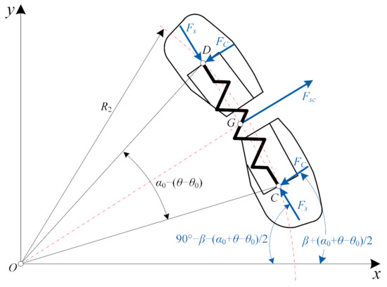
Figure 3.
Force analysis of spring.
Assume the linear stiffness of the spring is kt, the spring force Fs can be expressed as
Suppose the rotational speed of the DMF is n r/min in the working process, thus, the angular velocity is ω = 2 πn/60 rad/s. The centrifugal forces of the spring and the spring seat are Fsc and Fhc, respectively, and can be expressed as
The spring is balanced under the centrifugal force Fsc and the reaction forces action from two spring seats. The magnitudes of the reaction forces are equal to Fs and FC, respectively. The directions of these forces are shown in Figure 3. Therefore, FC can be obtained as
As shown in Figure 4, FN1 is the normal force of primary flywheel to spring seat, FN2 is the normal force of secondary flywheel to spring seat, Ff1 and Ff2 are the corresponding friction forces. The spring seat is balanced under the forces of Fs, Fsc2, Fhc, FN2, Ff2, FN1, and Ff1. The magnitudes and directions of Fs, Fsc2, Fh are known. The directions of FN2 and Ff2 are known, but their magnitudes are unknown. The magnitudes and directions of FN1 and Ff1 are unknown.
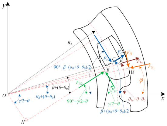
Figure 4.
Force analysis of the spring seat when relative rotational angle increases.
Frictional contact problems, which widely exist between parts in contact with each other, play an important role in mechanical engineering. How to accurately evaluate the friction characteristics between interfaces usually involves materials, mechanics, calculation methods, and so on. For the limitations of the analytical method and the development of high-speed computers, the numerical methods are becoming more and more important in the solution and the analysis of frictional contact problems, such as the Finite Element Method (FEM), the Boundary Element Method (BEM), the Meshfree methods and so on [32,33,34]. Besides, there are many studies on new analysis methods. Such as a strong form meshfree collocation method presented in [35], a novel adaptive isogeometric analysis meshfree collocation method in [36], and a contact domain method for a two-dimension frictional contact problem with large deformation in [37,38].
To simplify the analysis, here we use the classical Coulomb friction theory. The friction forces Ff1 and Ff2 can be written as
where μ1 and μ2 are the friction coefficients.
The position of point Q, which is the action point of the equivalent concentrated force between the primary flywheel and the spring seat, is expressed in polar coordinates (R3,φ), where φ is required to solve.
3.2.1. When Relative Rotational Angle Increases
As shown in Figure 4, when the relative rotational angle increases, according to the force balance, the following equation is obtained:
The distances between point E and force FN2, Ff2, FN1, Ff1, Fs, FC are respectively denoted by lEN2, lEf2, lEN1, lEf1, lEFs, and lEFc, which can be calculated as presented in Appendix A. For the spring seat mass center E, the below torque balance equation can be listed:
where the sign “±” depends on the position of point Q.
Let:
Equations (15) and (16) can be simplified as
The three parameters of FN1, FN2, and x3 can be obtained by solving the nonlinear Equation (18). The torque transmitted by the DMF can be expressed as
where m is the number of springs, Mf is the axial torque of friction bearing, which is generated by preload applied in the axial direction during assembly.
3.2.2. When Relative Rotational Angle Decreases
When relative rotational angle decreases, as shown in Figure 5, the following force balance equation is expressed as
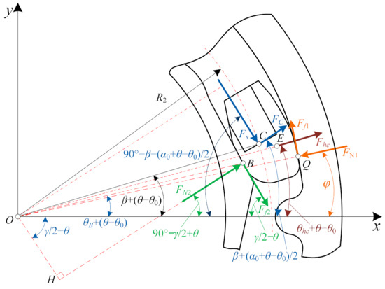
Figure 5.
Force analysis of spring seat when relative rotational angle decreases.
For the spring seat mass center E, according to the torque balance, we obtain the equation as
Let:
Equations (20) and (21) can be simplified as
At present, the torque transmitted by the DMF is
The stiffness of the DMF when the relative rotational angle increases and decreases are denoted by k+ and k–, respectively, which can be calculated with Equation (25).
4. Results and Discussion
The main geometric parameters of the DMF are as follows: R1 = 106 mm, R2 = 113 mm, R3 = 127.5 mm, Rhc = 116 mm, RA = 106 mm, γ = 135°, θ0 = 4°, θhc = 8°, α0 = 35°, β = 10°, and the maximum relative rotational angle θmax = 20°. Grease lubrication is adopted between the transmission parts, and the friction coefficient ranges from 0.01 to 0.05. Here, we take the friction coefficients μ1 = μ2 = 0.035. The stiffness of the straight spring kt = 8.76 N/mm, axial friction torque Tf = 7 N·m, the number of springs m = 6, the mass of the spring and the spring seat are ms = 21.73 g and mh = 11.51 g, respectively. The theoretical dynamic characteristics of the DMF including torque and stiffness can be obtained by theoretical analysis and calculation.
4.1. Torque and Stiffness Characteristics of the DMF
Figure 6 shows the torque and stiffness characteristics of the DMF at 3000 r/min. Due to friction influence, the torque when the relative rotational angle increases are obviously greater than that when the relative rotational angle decreases, which is called hysteresis characteristics. Before the spring seat contacts with the secondary flywheel, there is no contact force, and the contact torque is 0. Only the friction torque of the friction damping ring in the axial direction acts at this time, as shown in Figure 6a. When the relative rotational angle continues to increase, the transmission torque becomes to add. When the relative rotational angle decreases, the torque of the DMF will suddenly decrease, and it will continue to decrease with the decrease of the rotational angle until the spring seat is separated from the secondary flywheel.
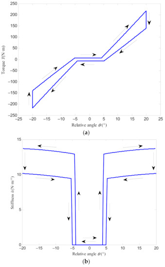
Figure 6.
Torque and stiffness characteristics of the DMF at a rotational speed of 3000 r/min: (a) torque characteristics; (b) stiffness characteristics.
Although the stiffness of the damping spring remains constant within the range of elastic deformation, the stiffness of the DMF is not constant when the relative rotational angle changes, as shown in Figure 6b. The greater the relative rotational angle, the greater the stiffness. Due to the friction influence, compared to the stiffness when the relative rotational angle increases, the stiffness when the relative rotational angle decreases is smaller. Before the spring seat contacts with the secondary flywheel, the stiffness of the DMF is 0. With the increase of relative rotational angle, the stiffness of the DMF increases from 0 to a certain value after the spring seat is in contact with the secondary flywheel, and then continuously increases with the addition of the relative rotational angle. Here, we define the difference of the relative angle that the contact action to produce torque when the relative angle increases and decreases is the lag angle.
Besides, the torque transmitted and the stiffness of the DMF also have specific symmetrical characteristics, namely, at two relative rotational angles with the same magnitude and opposite direction, the torque transmitted by the DMF is the same, the direction is opposite, and the magnitude and direction of the stiffness is the same.
4.2. Influence of Parameters on Torque and Stiffness Characteristics
When the geometric parameters are determined, rotational speed, the friction coefficient between parts, and structure mass will influence the forces between the transmission parts in the DMF. Next, the effects of speed, friction coefficient, and mass on the torque and stiffness of the DMF are analyzed.
4.2.1. Effect of Speed
Through calculation, the torque and stiffness characteristics of the DMF at speeds of 0, 3000, and 6000 r/min shown in Figure 7 can be obtained. From Figure 7a, it can be seen that when the relative rotational angle increases, the speed has a small effect on the torque, and the change of the transmitted torque is small for different speeds. However, when the relative rotational angle decreases, the torque decreases obviously with a larger speed. Thus, a larger speed will make the torque difference between the increases and decreases of the relative rotational angle greater. When the relative rotational angle is 20°, the torque difference is 70.2 N·m, 77.7 N·m and 100.0 N·m when the speed is taken as 0, 3000, and 6000 r/min, respectively. Besides, in a small angle range, after the relative rotational angle has passed the idle angle, there will be only axial friction torque Mf due to the influence of centrifugal force. And the higher the speed, the more obvious the hysteresis characteristics of the transmission torque.
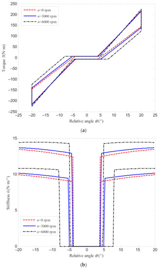
Figure 7.
Torque and stiffness characteristics of the DMF at different speeds: (a) torque characteristics; (b) stiffness characteristics.
As shown in Figure 7b, Regardless of whether the relative rotational angle increases or decreases, the higher the speed, the greater the overall stiffness of the DMF and the greater the lag angle will be. However, the greater the speed, the smaller the stiffness changes with the relative rotational angle.
4.2.2. Effect of Friction Coefficient
The torque and stiffness characteristics of the DMF when the speed is taken as 3000 r/min, and the friction coefficients are respectively given as 0.01, 0.03, and 0.05, are shown in Figure 8. It can be concluded that when the relative rotational angle increases, the torque and stiffness will turn to be greater with the increase of the friction coefficient. Moreover, when the relative rotational angle decreases, the torque and stiffness will turn small with the addition of the friction coefficient. Therefore, the larger the friction coefficient, the greater the difference of the torque and stiffness when the relative rotational angle increases and decreases. However, the friction coefficient has little influence on the lag angle, and the rotational angle corresponding to the initially produced torque is almost unchanged.
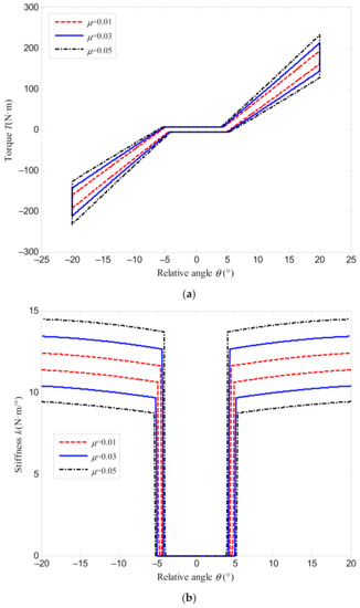
Figure 8.
Torque and stiffness characteristics of the DMF with different friction coefficients: (a) torque characteristics; (b) stiffness characteristics.
4.2.3. Effect of Spring Mass
Figure 9 shows the torque and stiffness of DMF at the speed of 3000 r/min when the spring mass is 10 g, 50 g, and 100 g, respectively. According to Figure 9a, the mass of the damping spring has an influence on the torque characteristics at small relative rotational angles. The greater the spring mass, the less torque is transmitted. However, the torque under different spring masses becomes close with the increase of rotational angle. The spring mass has a certain influence on the stiffness of the DMF, as shown in Figure 9b. When the spring mass turns larger, the overall stiffness will increase, and the change of stiffness becomes more gentle with relative rotational angles. In addition, when the spring mass becomes bigger, the angle at which the output torque starts to produce will increase.
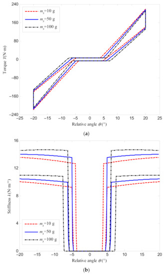
Figure 9.
Torque and stiffness characteristics of DMF with different spring mass: (a) torque characteristics; (b) stiffness characteristics.
4.2.4. Effect of Spring Seat Mass
Take the rotational speed equals 3000 r/min, the torque and stiffness of the DMF are analyzed with the mass of the spring seat is given as 10 g, 50 g, and 100 g, respectively, as shown in Figure 10. From Figure 10a, it is found that when the relative rotational angle increases, the addition of spring seat mass makes the transmitted torque greater. However, when the relative rotational angle decreases, the transmitted torque will turn smaller with a higher value of the spring seat mass.
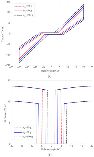
Figure 10.
Torque and stiffness characteristics of the DMF with different spring seat mass: (a) torque characteristics; (b) stiffness characteristics.
Figure 10b shows that the spring seat mass almost does not affect the stiffness of the DMF. The stiffness characteristic curves are close for different spring seat masses. The main difference is that larger spring seat mass makes the angle at which the output torque starts to produce become smaller when the relative rotational angle increases, and the angle at which the output torque starts to produce become greater when the relative rotational angle decreases. Thus, the lag angle increases with spring seat mass.
4.3. Dynamic Torque Characteristic Test of DMF
To prove the effectiveness of the theoretical analysis, a test on the dynamic torque characteristics of the DMF is conducted. The test is carried out on the DMF comprehensive test bench developed by the authors. The test bench mainly consists of a test bench base, frequency converter, variable frequency motor, rotary encoder, DMF, torque sensor, data acquisition card, brake, brake regulator, computer, and so on, as shown in Figure 11.
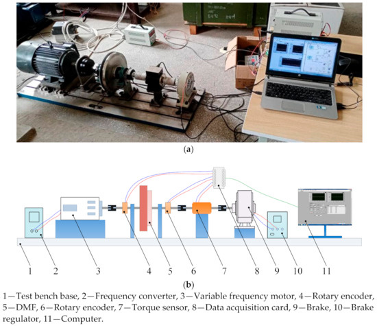
Figure 11.
Test bench of DMF: (a) actual structure of the test bench; (b) overall configuration of the test bench.
The specific test process is: the frequency conversion motor is controlled to rotate at a specific speed by making the frequency converter (the type is G510-G 30K0, and the frequency range is 0–50 Hz) at a corresponding frequency. The load torque generated by the brake (the type is PB-B2-10, the maximum torque of which is 100 N·m) is controlled through controlling DC of the brake regulator (the type is KTC800A, the DC range of which is 0–4 A). The torque sensor (the type is JN-DN3, the torque range it can test is 100 N·m, and the accuracy of the sensor is 0.3 N·m) is used to measure the real-time loading. The angular displacement of the primary flywheel and the secondary flywheel are measured by two rotary encoders (the type is SZGLK8028G2-3600-526K, and the accuracy of the rotary encoder is 3600 pulse/r) at both ends of the DMF through calculating the number of pulses signal. The subtraction of the rotational angles obtained by the two encoders is the relative rotational angle of the DMF. The data measured by the torque sensor and encoders are transmitted to the computer through the data acquisition card (the type is NI-USB-6210).
Considering that the maximum output torque of the variable frequency motor in the test bench is limited, the original damping springs of the DMF are removed and replaced with small stiffness springs. Then reassembled and tested. The stiffness of the replaced damping spring is kt = 1.72 N/mm, and the spring mass is ms = 9.72 g. The other structures and parameters remain unchanged, as shown in Figure 12.
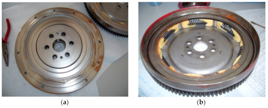
Figure 12.
DMF used for the test: (a) primary flywheel; (b) secondary flywheel.
For the DMF symmetry structure, the torque characteristics test of the DMF is processed in a single direction of rotation. The rotational speeds are set to be 1000 and 3000 r/min, respectively (the maximum speed of the motor for the test is 3000 r/min). The comparisons between the test results and the theoretical analysis results are shown in Figure 13. It can be seen that the theoretical analysis results are close to the test data in the rotational angle range of 0–16°. However, there is a certain difference between the test torque and the theoretical analysis results after 16°. The main reason is that two spring seats contact and begin to wedge with each other after the relative rotational angle exceeds 16°, as shown in Figure 14. Due to the wedging action, the slope of the test torque curve changes obviously, and it further increases the transmission torque. Through calculation, the relative error can be obtained. The average value of the error is below 5% at the angles from idle angle to 16°. In conclusion, the dynamic characteristic modeling and theoretical analysis of the DMF presented in this paper are valid.
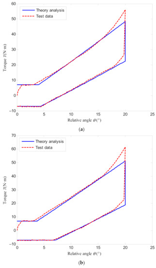
Figure 13.
Torque characteristics comparisons between theoretical analysis and test results: (a) n = 1000 r/min; (b) n = 3000 r/min.
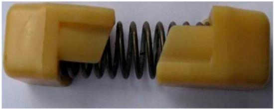
Figure 14.
Assembly of spring and spring seats.
5. Conclusions
To investigate the effects of centrifugal force and friction on the torque and stiffness characteristics of a circumferential short spring DMF, the mechanical analysis models of the transmission parts in the DMF are established by the discrete method. The torque action between the parts is deduced. The dynamic characteristics of the DMF including torque and stiffness are obtained through analysis and calculation. The influences of speed, friction coefficient, spring mass, and spring seat mass on the dynamic characteristics of the DMF are analyzed. Finally, the theoretical analysis is proved to be valid by the torque characteristic tests of DMF. The major conclusions are as follows:
- The transmission torque of the DMF has hysteresis characteristic and the torque and stiffness when the relative rotational angle increases are obviously greater than when the relative rotational angle decreases. The greater the relative rotational angle, the larger the torque and stiffness. Besides, the torque transmitted and the stiffness of the DMF also have specific symmetrical characteristics.
- Speed has little influence on the DMF torque when the relative rotational angle increases, but it has a great influence on the torque when the relative rotational angle decreases. A larger rotational speed makes the torque difference between the increases and decreases of the relative rotational angle greater, which results in more obvious hysteresis characteristics of transmission torque. Regardless of whether the relative rotational angle increases or decreases, the higher the speed, the greater the overall stiffness of the DMF and the lag angle will be. However, for a higher speed, the stiffness will change slower with a relative rotational angle.
- When the relative rotational angle increases, a larger friction coefficient will make the torque and stiffness greater. When the relative rotational angle decreases, the torque and stiffness will turn small with the addition of the friction coefficient. Therefore, the larger the friction coefficient, the greater the difference of the torque and stiffness when the relative rotational angle increases and decreases.
- The mass of the damping spring has an effect on the torque characteristics of DMF at small relative rotational angles. The greater the spring mass, the less torque is transmitted. However, the torque under different spring masses becomes close with the increase of rotational angle. The spring mass has a certain influence on the stiffness of the DMF. If the spring mass is increased, the overall stiffness will increase, and the changing process of stiffness will become more gentle with relative rotational angle.
- When the relative rotational angle increases, the addition of spring seat mass makes the transmitted torque greater. While when the relative rotational angle decreases, the transmitted torque will turn smaller with a higher value of the spring seat mass. Spring seat mass almost does not affect the stiffness of the DMF. Regardless of whether the rotational angle increases or decreases, the stiffness characteristic curves are basically the same.
In future work, the torque and stiffness of DMF are dynamic changing due to the variation of centrifugal force at different speeds, thus the vibration reduction of DMF in vehicle transmission system with considering the influence of centrifugal force is required to study. When the relative angle is large, the two spring seats will wedge into each other. Mechanical modeling and analysis are also very important. In addition, how to consider the structural deformation, contact action, and carry out more accurate modeling in combination with the work in this paper still requires further research.
Author Contributions
Conceptualization and methodology, L.Z. and L.S.; original draft preparation and editing, L.Z.; performing tests and investigations, Y.X., J.H., and L.Z.; analyzing the results and reviewing the article, Y.X. and J.H. All authors have read and agreed to the published version of the manuscript.
Funding
This work was supported by the National Natural Science Foundation of China (Grant No. 51805167), the Natural Science Foundation of Jiangxi Province (Grant No. 20171BAB216029), and the Foundation of Educational Department of Jiangxi Province (Grant No. GJJ170403).
Data Availability Statement
Not applicable.
Conflicts of Interest
The authors declare no conflict of interest.
Appendix A
The linear equation of force FN2 is
where
The linear equation of force Ff2 is
where
The linear equation of force FN1 is
where
The linear equation of force Ff1 is
where
The linear equation of force Fs is
where
The linear equation of force FC is
where
The polar coordinates of point E are (Rhc, θE), where θE = θhc + θ − θ0, thus the rectangular coordinate of point E (xE, yE) is obtained:
The distances between point E and force FN2, Ff2, FN1, Ff1, Fs, FC are denoted by lEN2, lEf2, lEN1, lEf1, lEFs and lEFc, respectively, which can be expressed as
References
- Szpica, D. Modelling of the operation of a Dual Mass Flywheel (DMF) for different engine-related distortions. Math. Comp. Model. Dyn. Syst. 2018, 24, 643–660. [Google Scholar] [CrossRef]
- Chen, L.; Zhang, X.; Yan, Z.F.; Zeng, R. Matching model of dual mass flywheel and power transmission based on the structural sensitivity analysis method. Symmetry 2019, 11, 187. [Google Scholar] [CrossRef]
- More, S.; Medankar, P.; Nagargoje, M. Design and development of dual mass flywheel system. Int. J. Innov. Res. Sci. Eng. Technol. 2015, 4, 964–969. [Google Scholar] [CrossRef]
- Schaper, U.; Sawodny, O.; Mahl, T.; Blessing, U. Modeling and Torque Estimation of an Automotive Dual Mass Flywheel. In Proceedings of the 2009 American Control Conference, St. Louis, MO, USA, 10–12 June 2009; pp. 1207–1212. [Google Scholar] [CrossRef]
- Theodossiades, S.; Gnanakumar, M.; Rahnejat, H.; Kelly, P. Effect of a dual–Mass flywheel on the impact–induced noise in vehicular powertrain systems. Proc. Inst. Mech. Eng. Part D J. Automob. Eng. 2006, 220, 747–761. [Google Scholar] [CrossRef]
- Lü, Z.H.; Chen, T. Design of the Elastic Characteristics of Torsional Damper with Double Mass Flywheel and Circumferential Spring. Automot. Eng. 2006, 28, 73–77. [Google Scholar]
- Li, Y.N.; Qian, X.J.; Sun, W. Simulation and Study on Dynamic Load Characteristics of Arc Spring. China Mech. Eng. 2012, 23, 155–160. [Google Scholar]
- Mahl, T.; Sawodny, O. Modelling of an automotive dual mass flywheel. In Proceedings of the IFAC Symposium on Mechatronic Systems, Cambridge, MA, USA, 13–15 September 2010; pp. 517–523. [Google Scholar] [CrossRef]
- Kim, T.H.; Song, H.L.; Hwang, S.H.; Kim, H.S. Analysis of Dual Mass Flywheel Using Discrete Arcspring Model. Key Eng. Mater. 2006, 326, 1607–1610. [Google Scholar] [CrossRef]
- Huang, Z.; Chen, D.M.; Wang, D.J.; Sun, W.; Guo, X.L. Design and Simulation Analysis on Arc Helix Spring of Dual Mass Flywheel. J. Acad. Armored Force Eng. 2009, 23, 31–35. [Google Scholar]
- Lü, Z.H.; Wu, Z.G.; Chen, T. The Design Principles and Performance Analysis of DMF-CSS Torsional Damper. Automot. Eng. 2003, 25, 493–497. [Google Scholar]
- He, L.P.; Xia, C.G.; Chen, S.D.; Guo, J.W.; Liu, Y. Parametric Investigation of Dual-Mass Flywheel Based on Driveline Start-Up Torsional Vibration Control. Shock. Vib. 2019, 2019, 3171698. [Google Scholar] [CrossRef]
- Tang, X.; Hu, X.; Yang, B.W.; Yu, H. Novel Torsional Vibration Modeling and Assessment of a Power-Split Hybrid Electric Vehicle Equipped With a Dual-Mass Flywheel. IEEE Trans. Veh. Technol. 2018, 67, 1990–2000. [Google Scholar] [CrossRef]
- Chen, L.; Shi, W.K.; Chen, Z.Y. Research on Damping Performance of Dual Mass Flywheel Based on Vehicle Transmission System Modeling and Multi-Condition Simulation. IEEE Access 2020, 8, 28064–28077. [Google Scholar] [CrossRef]
- Shi, W.K.; Long, Y.; Lu, Y.D. Study on multistage non-linear dual mass flywheel damper. J. Vib. Shock. 2009, 28, 92–96. [Google Scholar]
- Song, L.Q.; Zeng, L.P.; Zhang, S.P.; Zhou, J.D.; Niu, H.E. Design and analysis of a dual mass flywheel with continuously variable stiffness based on compensation principle. Mech. Mach. Theory. 2014, 79, 124–140. [Google Scholar] [CrossRef]
- Song, L.Q.; Zhou, J.D.; Wu, R.H.; Yin, Y.M.; Luo, S.M.; Tian, H.Y.; Fan, Z.Z. Research and Application on Design Theory of Friction Dual Mass Flywheel with Double-stage Piecewise Variable Stiffness. J. Mech. Eng. 2012, 48, 150–157. [Google Scholar] [CrossRef]
- Li, G.H.; Hu, J.J.; Qin, D.T. Study on natural torsional vibration characteristics of dual mass flywheel-radial spring type torsional vibration damper. China Mech. Eng. 2008, 19, 1800–1805. [Google Scholar]
- Zu, Q.H.; Chen, Z.Y.; Shi, W.K.; Mao, Y.; Chen, Z.Y. Torsional vibration semiactive control of drivetrain based on magnetorheological fluid dual mass flywheel. Math. Probl. Eng. 2015, 2015, 608737. [Google Scholar] [CrossRef]
- Kang, T.S.; Kauh, S.K.; Ha, K.P. Development of the displacement measuring system for a dual mass flywheel in a vehicle. Proc. Inst. Mech. Eng. Part. D J. Automob. Eng. 2009, 223, 1273–1281. [Google Scholar] [CrossRef]
- Sangue, S.; Lepoint, G.; Le Bournault, T. New approach to measure instantaneous angular behavior of a dual mass flywheel. In Proceedings of the Seoul 2000 World Automotive Congress, Seoul, Korea, 12–15 June 2000; pp. 12–15. [Google Scholar]
- Wu, F.; Mao, H. Dual Mass Flywheel Torsional Vibration Test-bed. J. Wuhan Univ. Technol. 2010, 32, 758–761. [Google Scholar]
- Tutuncu, N. Effect of anisotropy on stresses in rotating discs. Int. J. Mech. Sci. 1995, 37, 873–881. [Google Scholar] [CrossRef]
- Fairuz, Z.M.; Jahn, I.; Abdul-Rahman, R. The effect of convection area on the deformation of dry gas seal operating with supercritical CO2. Tribol. Int. 2019, 137, 349–365. [Google Scholar] [CrossRef]
- Yuan, F.; Zhu, X.C.; Du, Z.H. Experimental investigation for the effect of rotation on three-dimensional flow field in film-cooled turbine. Chin. J. Mech. Eng. 2007, 20, 10–15. [Google Scholar] [CrossRef]
- Huang, J.H.; Wei, J.H.; Qiu, M.X. Laminar flow in the gap between two rotating parallel frictional plates in hydro-viscous drive. Chin. J. Mech. Eng. 2012, 25, 144–152. [Google Scholar] [CrossRef]
- Xu, C.; Zhang, J.F.; Feng, P.F.; Yu, D.W.; Wu, Z.J. Characteristics of stiffness and contact stress distribution of a spindle-holder taper joint under clamping and centrifugal forces. Int. J. Mach. Tools Manuf. 2014, 82–83, 21–28. [Google Scholar] [CrossRef]
- Feng, P.F.; Yu, D.W.; Wu, Z.J.; Uhlmann, E. Jaw-chuck stiffness and its influence on dynamic clamping force during high-speed turning. Int. J. Mach. Tools Manuf. 2008, 48, 1268–1275. [Google Scholar] [CrossRef]
- Abadian, N.; Gheisari, R.; Keivani, M.; Kanani, A.; Mokhtari, J.; Rach, R.; Abadyan, M. Effect of the centrifugal force on the electromechanical instability of U-shaped and double-sided sensors made of cylindrical nanowires. J. Braz. Soc. Mech. Sci. Eng. 2016, 38, 2129–2148. [Google Scholar] [CrossRef]
- Hashimoto, H.; Wada, S.; Murayama, Y. An Influence of Centrifugal Force on the Performances of Thermo-hydrodynamic Turbulent Thrust Bearings. Bull. JSME 1984, 27, 1230–1236. [Google Scholar] [CrossRef][Green Version]
- Liu, C.Z.; Qin, D.T.; Liao, Y.H. Dynamic modeling and analysis of high-speed planetary gear including centrifugal force. J. Braz. Soc. Mech. Sci. Eng. 2017, 39, 3769–3778. [Google Scholar] [CrossRef]
- Belhocine, A.; Abdullah, O.I. A thermomechanical model for the analysis of disc brake using the finite element method in frictional contact. J. Therm. Stresses 2020, 43, 305–320. [Google Scholar] [CrossRef]
- Kosior, F.; Guyot, N.; Maurice, G. Analysis of frictional contact problem using boundary element method and domain decomposition method. Int. J. Numer. Meth. Engng. 2015, 46, 65–82. [Google Scholar] [CrossRef]
- Park, Y.H.; Kim, N.H.; Yim, H.J. Reliability-Based Design Sensitivity Analysis and Optimization for the Hyper-Elastic Structure Using the Meshfree Method. In Proceedings of the 2000 ASME Pressure Vessels and Piping Conference, Seattle, WA, USA, 23–27 July 2000; pp. 107–114. [Google Scholar]
- Almasi, A.; Kim, T.Y.; Laursen, T.A.; Song, J.H. A strong form meshfree collocation method for frictional contact on a rigid obstacle. Comput. Methods Appl. Mech. Engrg. 2019, 357, 112597. [Google Scholar] [CrossRef]
- Nguyen-Thanh, N.; Li, W.D.; Huang, J.Z.; Srikanth, N.; Zhou, K. An adaptive isogeometric analysis meshfree collocation method for elasticity and frictional contact problems. Int. J. Numer. Meth. Engng 2019, 120, 209–230. [Google Scholar] [CrossRef]
- Oliver, J.; Hartmann, S.; Cante, J.; Weyler, R.; Hernández, J. A contact domain method for large deformation frictional contact problems. Part 1: Theoretical basis. Comput. Methods Appl. Mech. Engrg. 2009, 198, 2591–2606. [Google Scholar] [CrossRef]
- Hartmann, S.; Oliver, J.; Weyler, R.; Cante, J.; Hernández, J. A contact domain method for large deformation frictional contact problems. Part 2: Numerical aspects. Comput. Methods Appl. Mech. Engrg. 2009, 198, 2607–2631. [Google Scholar] [CrossRef]
Publisher’s Note: MDPI stays neutral with regard to jurisdictional claims in published maps and institutional affiliations. |
© 2021 by the authors. Licensee MDPI, Basel, Switzerland. This article is an open access article distributed under the terms and conditions of the Creative Commons Attribution (CC BY) license (https://creativecommons.org/licenses/by/4.0/).