Abstract
In this paper, we aim to reveal the influence of fault fracture zones on the stability of submarine tunnels and the surrounding rock under different water and drainage measures. Firstly, four typical working conditions of submarine tunnels intersecting with fault fracture zones were selected. On the basis of the typical cross section of the intersections of submarine tunnels and faults, they were divided into four working conditions. Then, the displacement and plastic zones of the surrounding rock of the tunnel were studied, and the stability of the rock surrounding the submarine tunnel was discussed. This research structure indicates that the bending moment and axial force of the lining structure of the submarine tunnel increase with increasing sealing degree, but the safety factor exhibits a downward trend. When the fault fracture zone goes through the section above the tunnel axis, the bending moment and axial force at the lining vault are greater than the other working conditions, and the displacement of the surrounding rock at the vault and spandrel is prominent. When the fault fracture zone completely passes through the tunnel, the safety factor of the lining structure is at its lowest, and the displacement of the surrounding rock at the arch waist develops laterally. When the fault fracture zone passes through the part below the tunnel axis, the arch foot displacement converges significantly, and the surrounding rock displacement exhibits a downward inclination. In addition, the plastic zone is mainly developed in the arch and the shoulder. These research results provide a reliable reference for tunnel design and excavation support.
1. Introduction
As an important transportation method, submarine tunnels are also a major development trend in future transportation. All countries in the world are striving to promote the development of submarine tunnels [1,2,3]. However, relevant research and design and construction and operation management experience is relatively scarce [4]. The environment of submarine tunnels is complex and changeable, and there are many influencing factors, such as the properties of the surrounding rock and the waterproofing of the submarine tunnel. They are more difficult to construct in areas where the rock is significantly broken due to dense fault or fracture zones. If design and construction are carried out in an improper manner, this can lead to local deformation or even catastrophic accidents, such as water gushing or collapse, greatly increasing the difficulty of support. Therefore, it is necessary to study the influence of different fault fracture zones on the stability of the surrounding rock of submarine tunnels. This study is of great significance for improving the overall stability of submarine tunnels under different fracture zones.
A lot of research has been carried out on the stability of submarine tunnels and the stress characteristics of the lining structures. Based on the ANSYS finite element program and the load–structure model, Li et al. [5] analyzed the stress of eight lining sections with different design parameters of the Jiaozhou Bay Submarine Tunnel Project in Qingdao. Zhang [6] mainly used model tests to study the Xiamen Xiangan Submarine Tunnel; he analyzed the stress field and seepage field, as well as the mechanical characteristics of the lining structure under the interaction of the stress field and the seepage field. S. C. Li et al. [7] carried out a fluid–solid coupling model test of the Jiaozhou Bay Submarine Tunnel in Qingdao. In the course of the study, similar materials and a new independently developed model system were used, and the displacement field and seepage field of the surrounding rock and the variation law of wall pressure during the construction of the submarine tunnel were obtained through experimental study. Wu [8] combined numerical simulation and model testing to study the distribution law of the water load behind the grouting ring and the lining of the Xiamen Xiangan Submarine Tunnel. Wang and Tan [9] increased the analysis of field-measured data and studied the hydraulic characteristics of the composite lining of the Xiangan Submarine Tunnel in Xiamen. Wang et al. [10] considered the permeability of seawater using the finite element limit analysis method, and analyzed the stability of the Qinghai-Huanghai Submarine Highway Tunnel with respect to the local fractured zone before and after grouting reinforcement. Wang [11] used the engineering analogy method, the mechanical analysis method, and the permissible leakage water method to preliminarily determine that the reinforcement scope of the main tunnel should be more than 5 m outside the excavation contour line. Based on the structural deformation, the reinforcement effect of grouting with different thicknesses in the fault fracture zone was analyzed on the basis of numerical simulation. Qiao et al. [12], aiming at the problem of water gushing from cracks in fracture zones, discussed the tunnel filling construction scheme of the fault fracture zone, and discussed in detail advanced drilling and advanced prefilling and filling parameters and filling processes. Nima Noii et al. [13] simulated crack propagation under isotropic and anisotropic conditions by Bayesian inversion and verified its correctness. On the basis of Bayesian inversion, Amirreza Khodadadian [14] et al. focused on the uncertainty of the parameters of solid material and the critical energy release rate in order to solve the problem of crack propagation. Wang et al. [15] developed a method for fluid–solid coupling stability analysis in the surrounding rock of submarine tunnels with broken zones under the action of seawater osmotic pressure, and applied this method to the Qinghuang submarine tunnel project in order to calculate and analyze the seepage field and the seepage stability of tunnel’s surrounding rock under two conditions: water shutoff and without water blocking. Wang and Li [16] studied the influence of different grouting reinforcement materials and different thicknesses of grouting reinforcement circles on the stress and deformation of the surrounding rock and the initial support of the tunnel when the tunnel passes through fault fracture zones using the three-dimensional finite element method. Su et al. [17] studied the influence of cracks in different positions of the lining on the stability of the tunnel on the basis of a three-dimensional model experiment, and obtained the deformation, internal force and deterioration law of precast crack lining in different positions. Zhou et al. [18] examined the engineering design and construction of Jiaozhou Bay Submarine Tunnel in Qingdao, and analyzed the construction risk of crossing the fault fracture zone using the risk analysis and evaluation method, and put forward risk countermeasures. Wang et al. [19] took a submarine tunnel in a locally broken zone as an example, and used the finite element limit analysis method to analyze the stability of submarine tunnel rock mass before and after grouting reinforcement. Ye et al. [20] evaluated the three-dimensional influence of the loose contact state of the surrounding rock lining on the mechanical behavior of the lining structure with respect to different degrees of lining compactness and different contact areas of the surrounding rock lining, and classified the degree of influence of the safety of the lining structure under a loose contact state.
The above researchers have studied and summarized the mechanical characteristics of submarine tunnel lining structures, as well as some influencing factors of submarine tunnel stability. However, to date, there have been few studies on the impact of fault location and different water and drainage measures on the overall stability of submarine tunnels. Therefore, when submarine tunnels cross fault fracture zones, the effects of different degrees of water and drainage measures on the stability of the submarine tunnel and the surrounding rock need further study.
2. Engineering Geological Characteristics
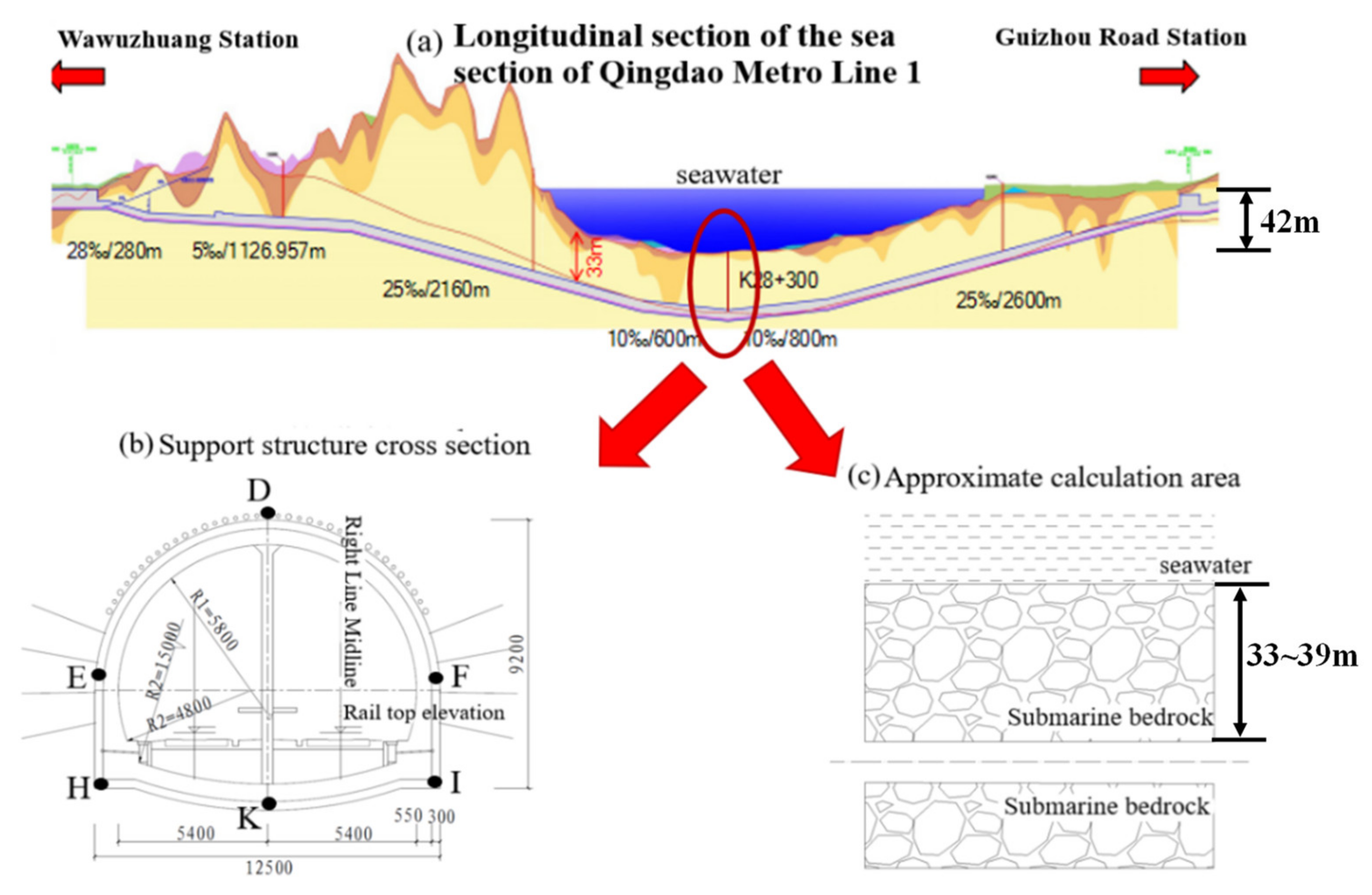
The total distance between Wawuzhuang Station and Guizhou Road Station on Qingdao Metro Line 1 is about 8.077 km, of which the sea section is 3.49 km long. The longitudinal section diagram of Qingdao Metro Line 1 is shown in Figure 1a, the cross-section diagram of submarine tunnel lining structure is shown in Figure 1b, and the study calculation area is similar to that shown in Figure 1c.

Figure 1.
Overview of the Qingdao metro line 1 submarine tunnel: (a) longitudinal section of the submarine tunnel; (b) cross-sectional view of submarine tunnel support structure; (c) approximate calculation area [21].
The submarine tunnel is V-shaped, and the maximum distance between the surrounding rock and the sea water is 42 m. The thickness of the rock cover in the arch of the tunnel is about 33~39 m, and the groundwater conditions are abundant. Points D, E, F, H, I and K were the analysis points selected for the subsequent research.
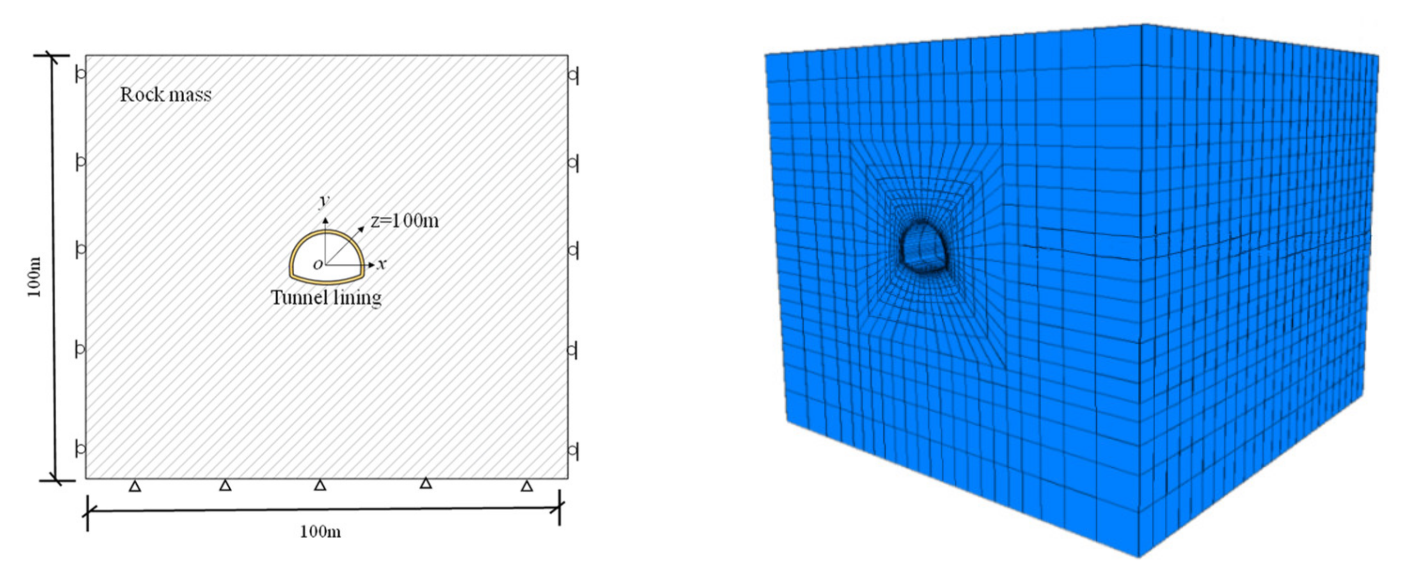
As shown in Figure 2, the model size was 100 m × 100 m × 100 m (height × width × thickness), and the ground was modeled using hexahedral element zones. Normal displacement constraints were applied on the top, left and right surfaces, and water pressure and gravity were applied on the top surface. The Mohr Coulomb model was adopted for the simulation.

Figure 2.
Modeling of submarine tunnel.
The fault fracture zone contains fragmented rock and multiple types of chlorite debris several centimeters wide. The geophysical survey shows an anomalous zone, in the East–West direction, with an inclination angle of 25°. It is estimated that the width of the fracture zone is about 7 m, with influence belts ranging from several meters to ten meters on both sides. According to the Specification for Design of Highway Tunnels (JTG 3370.1-2018), the surrounding rock for submarine tunnels is determined as grade IV, and the lining is grade IVb. The mechanical properties of the surrounding rock and the mechanical properties of the fault fracture zone are shown in Table 1.

Table 1.
Parameters of mechanical properties of surrounding rock.
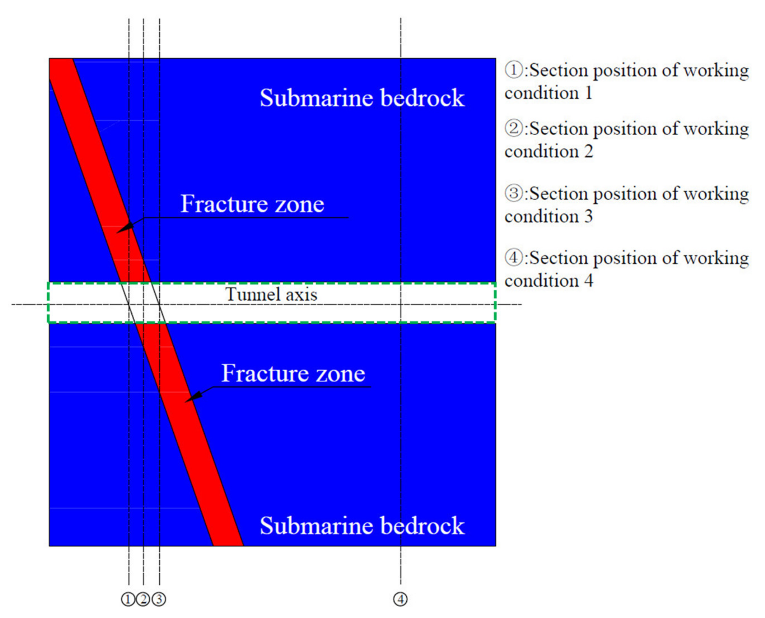
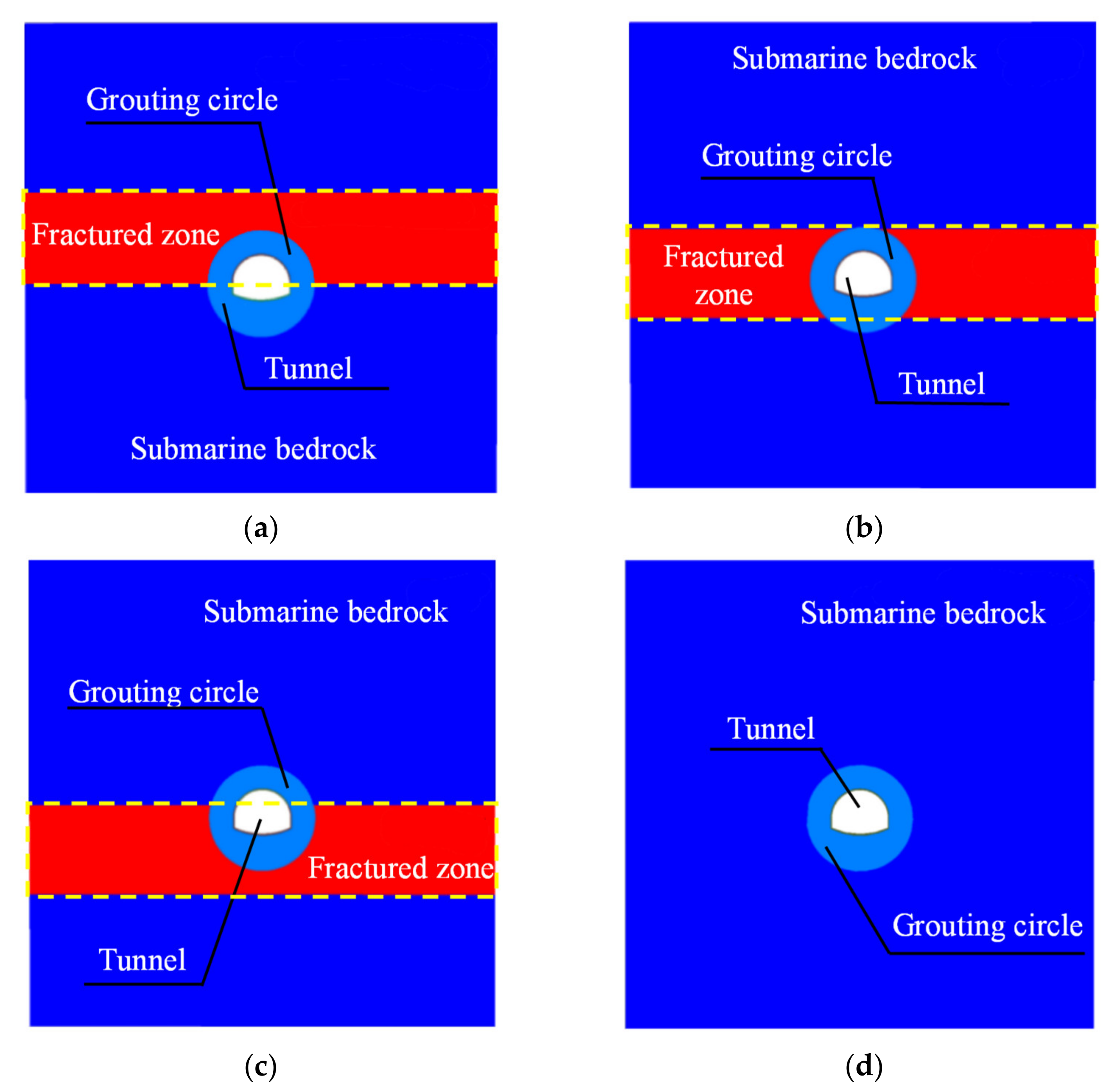
As shown in Figure 3, four representative sections were selected at the intersection of the submarine tunnel and the fault, denoted as Case 1, Case 2, Case 3, and Case 4, respectively. In Figure 4, the dark blue part is the submarine bedrock, the light blue is the grouting ring, and the red part is the fault fracture zone. A fluid–solid coupling simulation was performed for the above four working conditions using the FLAC3D numerical simulation software. The influence of the fault fracture zone on the overall stability of the submarine tunnel under different working conditions was compared and analyzed.

Figure 3.
Schematic diagram of the longitudinal section of a submarine tunnel orthogonally crossing the fault fracture zone.

Figure 4.
Section diagrams of four representative working conditions at the intersection of submarine tunnels and faults: (a) Working condition 1; (b) Working condition 2; (c) Working condition 3; (d) Working condition 4.
3. Analysis of the Influence of the Fault Fracture Zone on the Lining Structure of Submarine Tunnels
The stress of the lining structure is a result of the combined action of the seepage field and the stress field. Therefore, the external water pressure to which the lining structure is subjected will vary under different water blocking and drainage limits. The measures of different degrees of water blocking and drainage are replaced with different lining permeability coefficients, in accordance with the equivalent continuous medium distribution model. The lining permeability coefficient of a completely unblocked lining is 1.11 × 10⁻⁶ m/d, and the lining permeability coefficient with 25% plugging is 0.84 × 10⁻⁶ m/d; the permeability coefficient of 50% plugging is 0.56 × 10⁻⁶ m/d, the permeability coefficient of 75% plugging is 0.28 × 10⁻⁶ m/d, and the permeability coefficient of complete plugging is 0, i.e., impervious to water.
3.1. Analysis of the Influence of Water Blocking and Drainage Restriction on the Displacement of Submarine Tunnel Lining Structures Affected by Fault
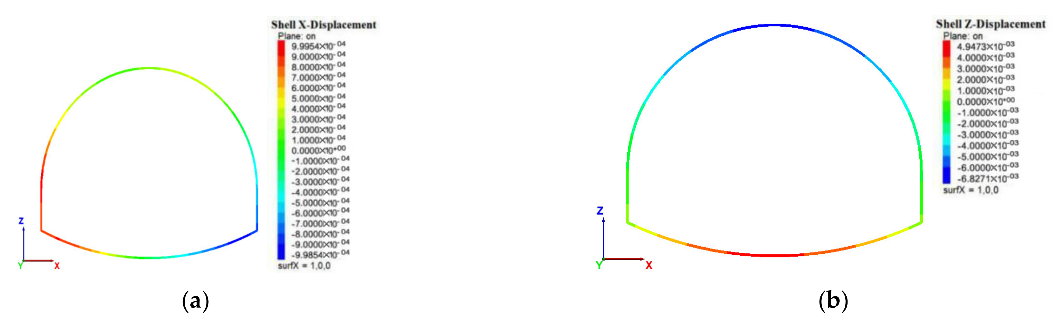
The displacement of the submarine tunnel lining can be divided into two directions: the settlement of arch roof and the convergence of the arch foot. The settlement of the arch roof is mainly a vertical displacement of the lining structure, while the convergence of the arch foot is a horizontal displacement of the lining structure. When the plugging degree is 50%, the displacement cloud diagram of the lining structure is shown in Figure 5. The maximum horizontal displacement occurs at the left and right arch foot, and the maximum vertical displacement occurs at the arch roof and the inverted arch. Therefore, point D at the arch roof was selected to analyze the settlement of the lining structure, and points H and K at the arch foot were selected to analyze the convergence of the lining structure. The coupling calculation for the fluid structure was performed under the above four working conditions.

Figure 5.
Displacement cloud image of the lining structure: (a) horizontal displacement cloud diagram; (b) vertical displacement cloud diagram.
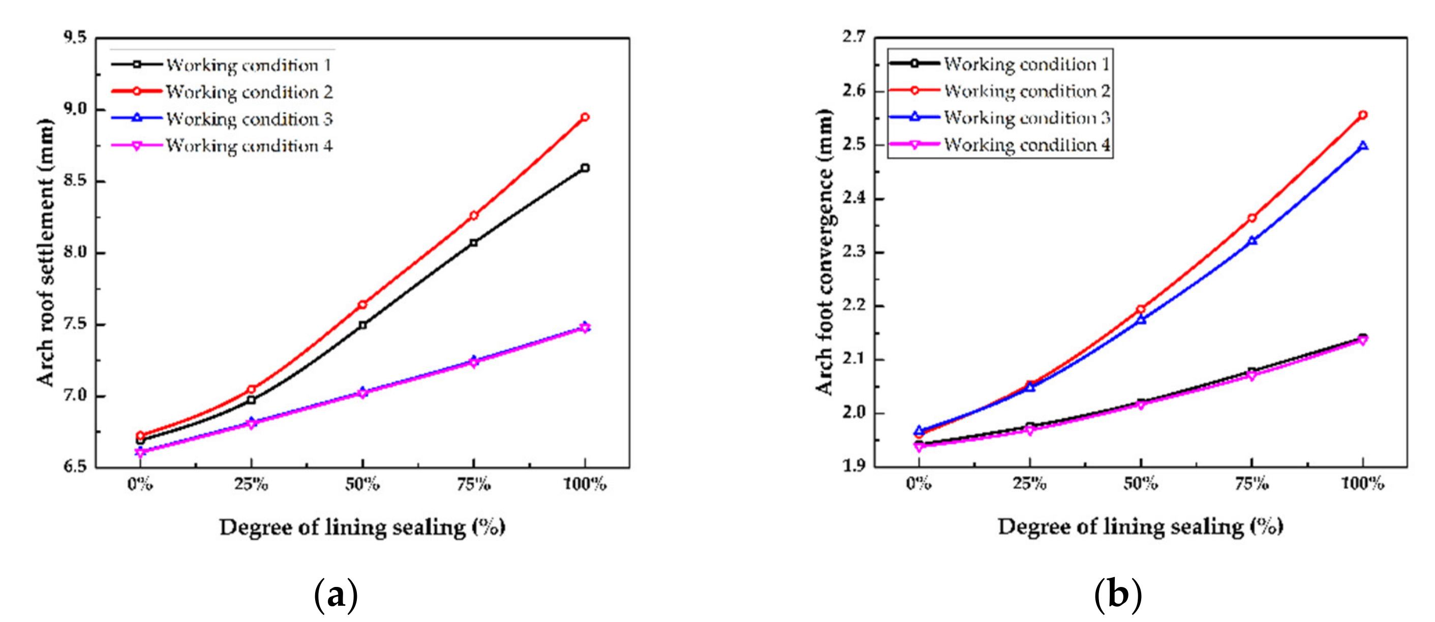
As shown in Figure 6, as the degree of plugging continues to increase, both the settlement of the vault and the convergence of the arch foot gradually increase. When the upper part of the submarine tunnel passes through the fault fracture zone, the settlement of the vault increases compared to Condition 4, but the convergence of the arch foot is almost unchanged, because the position of the arch foot is located in the seabed bedrock, limiting the deformation of the arch foot. When the lower half of the submarine tunnel passes through the fault fracture zone, the convergence of the arch foot increases in comparison to Condition 4; because the arch foot position is located in the fault, which is greatly affected by the fault, the displacement is large. When the cross-section of the submarine tunnel is located in the fault fracture zone, the settlement of the arch roof and the convergence of the arch foot both increase, and the deformation will be larger than that under other working conditions. When the submarine tunnel structure is completely located within the fracture zone, the settlement of the arch top is 8.951 mm, and the arch foot convergence is 2.557 mm. When semi-blocking is adopted, the arch settlement is 7.641 mm, and the arch foot convergence is 2.195 mm. It can be seen that when the submarine tunnel is constructed in the fault fracture zone, taking appropriate water blocking and drainage measures can effectively suppress the deformation of the lining structure. When the lining structure is located within the fault fracture zone, the sensitivity to the degree of plugging of the settlement of the arch top and the convergence of the arch foot is greater.

Figure 6.
Deformation tendency of the arch roof and the arch foot under different sealing conditions under different working conditions: (a) settlement and sealing degree of arch roof; (b) convergence and sealing degree of the arch foot.
3.2. Analysis of the Effect of Water Blocking and Drainage Restriction on the Internal Force of the Lining Structure of a Submarine Tunnel Affected by Faults
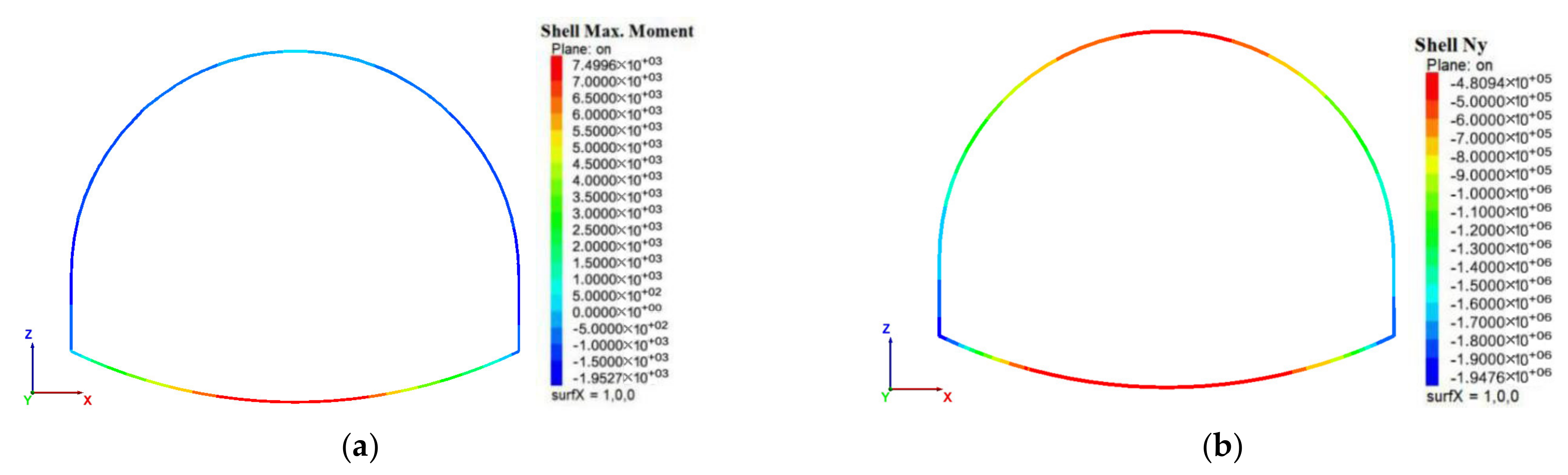
Four key parts—the arch roof, arch waist, arch foot and inverted arch—of the submarine tunnel lining structure were selected for force analysis. As shown in Figure 7, the maximum bending moment of the lining structure appears at the inverted arch, while the maximum axial force occurs at the inverted arch and the arch roof. To comprehensively solve the safety factor of the lining structure, the internal force analysis was carried out at four points: point D of the arch roof, points E and F of the arch waist, points H and K of the arch foot, and point I of the inverted arch.

Figure 7.
Moment and axial force cloud diagram of the lining structure: (a) moment of the lining structure; (b) axial force of the lining structure.
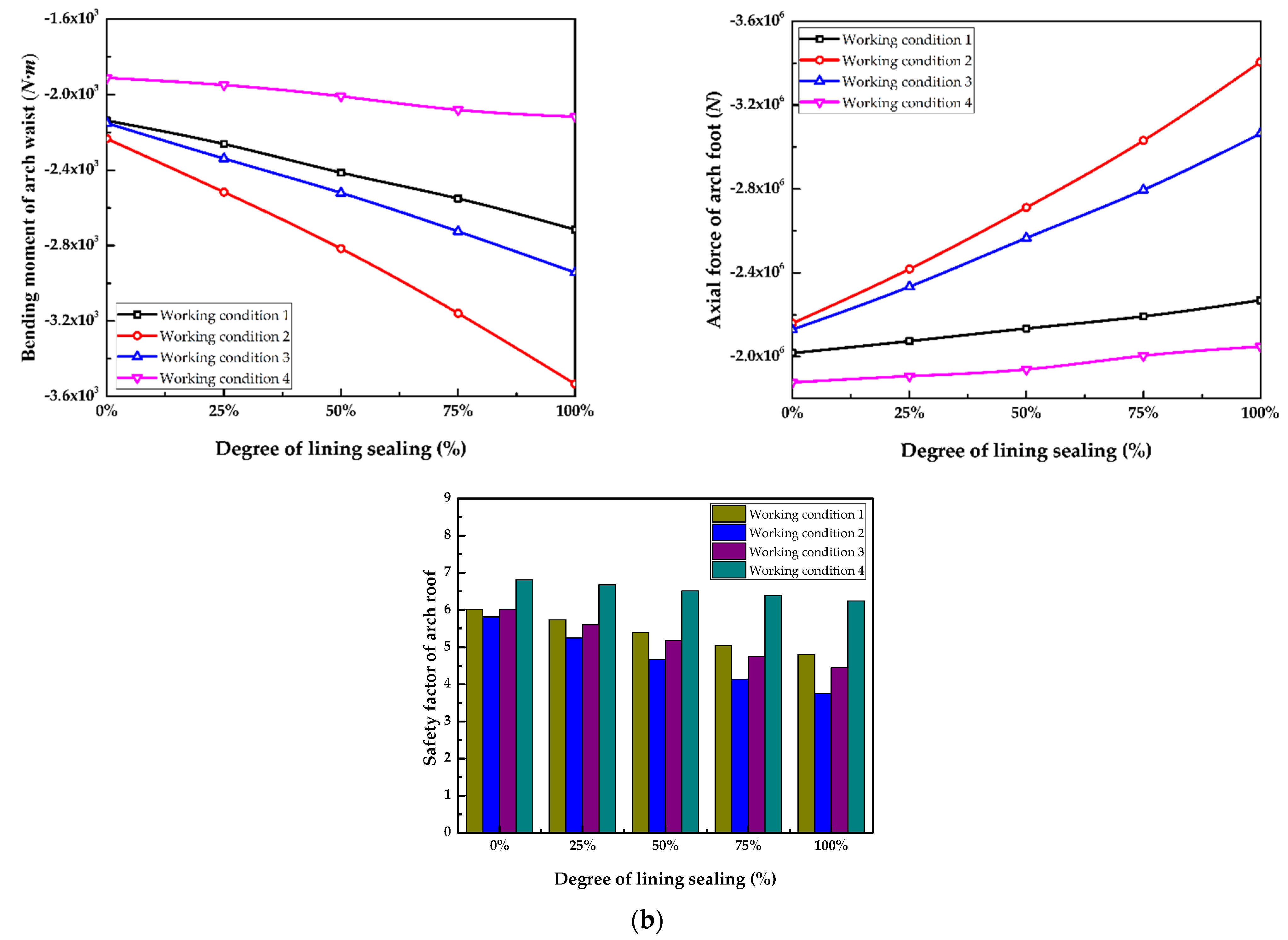
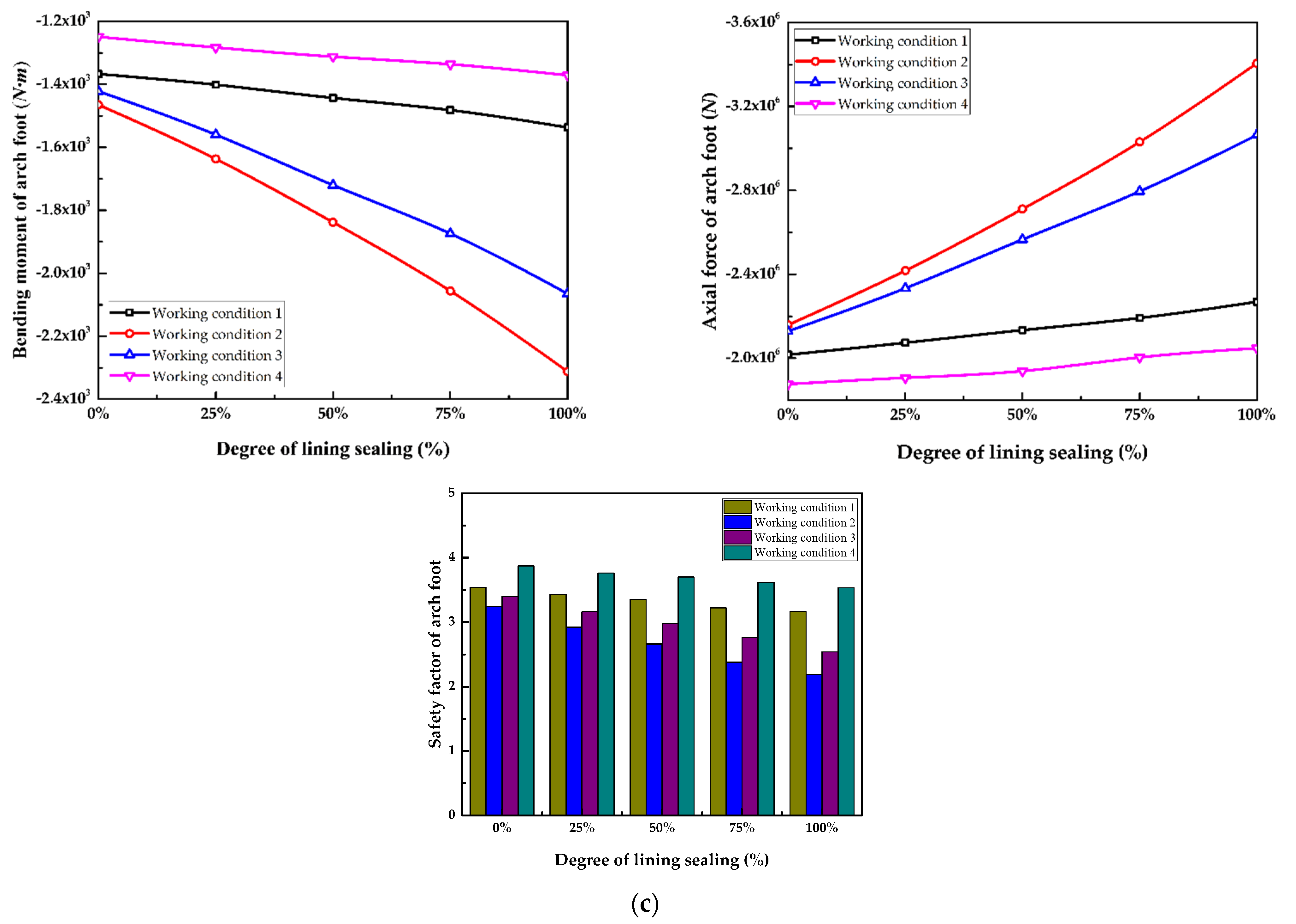
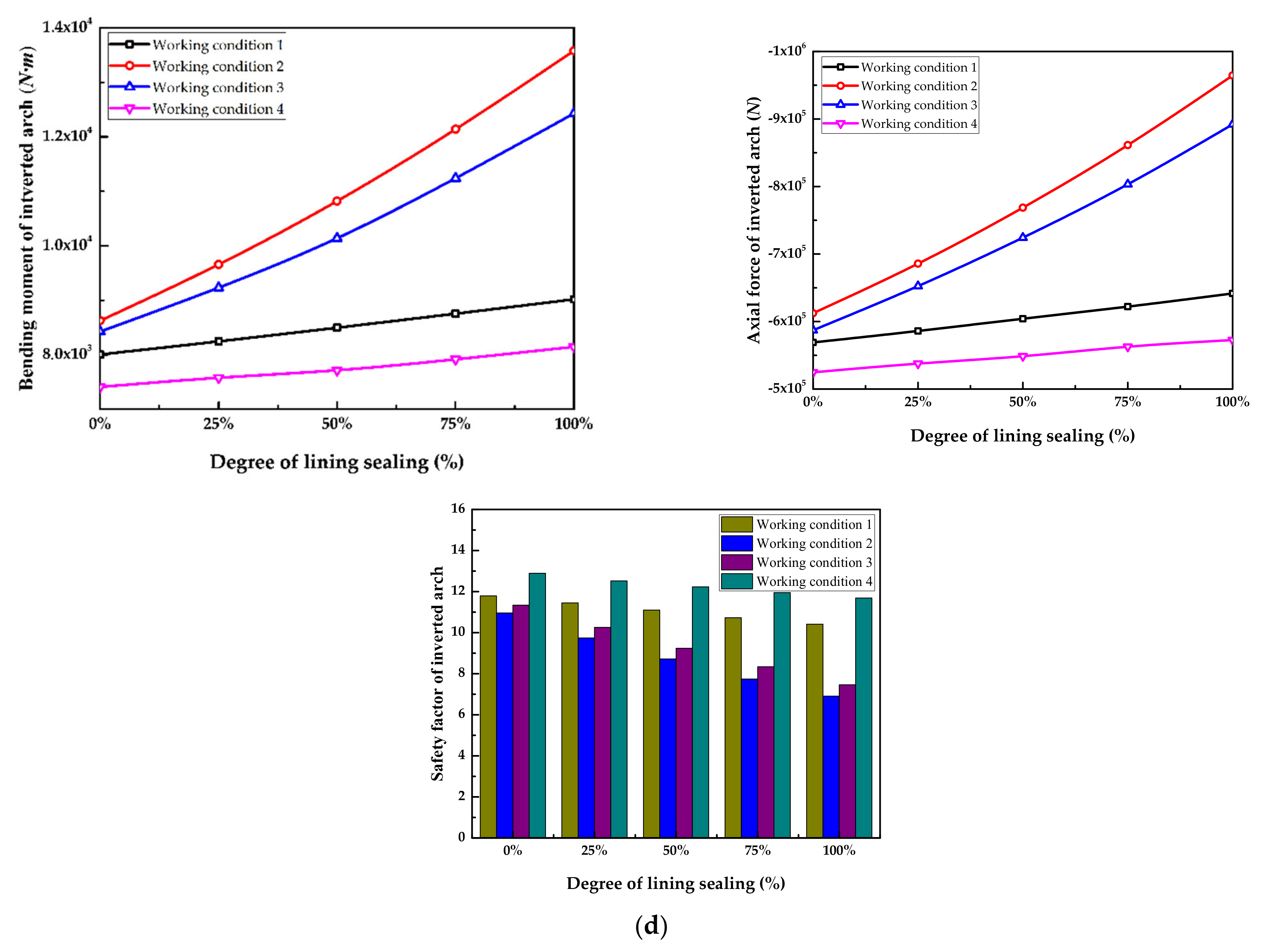
As shown in Figure 8, as the degree of sealing is increased, the bending moments and axial forces of the arch roof, arch waist, arch foot, and inverted arch of the lining structure of the submarine tunnel increase, while the corresponding safety factors decrease. When the upper half of the submarine tunnel passes through the fault fracture zone, that is, Condition 1, the arch roof of the lining structure is located in the fault fracture zone; because the supporting structure is subject to large forces, the bending moment and axial force at the arch roof position increase significantly compared with Case 4, and the rate of change is greater, although the increase rate is slightly lower than in Case 2. Because the position of the arch roof in Case 3 is located in the bedrock section of the submarine tunnel, its support deformation is relatively small, and the internal force changes are not obvious, which is almost the same as the internal force in Case 4. Therefore, the comparative internal force at the arch roof under different working conditions is as follows: Working condition 2 > Working condition 1 > Working condition 3 > Working condition 4. Because the safety factor and the internal force are negatively correlated, the comparative safety factors at the arch roof are as follows: Condition 4 > Condition 3 > Condition 1 > Condition 2. When the lower half of the submarine tunnel passes through the fracture zone, that is, Condition 3, the position of the inverted arch and the arch foot are located within the fault fracture zone, the arch waist is located at the vertical junction of the lining structure, and the fault fracture zone, and the arch roof is located in the subsea bedrock. Under this working condition, the arch waist and arch foot and the inverted arch are affected by the fault fracture zone, the internal force is greater than that under Working condition 1, and the rate of increase is faster, although it is also smaller than the internal force under Working condition 2. Therefore, the comparative internal forces at the arch waist, the arch foot and the inverted arch are as follows: Working condition 2 > Working condition 3 > Working condition 1 > Working condition 4; the comparative safety factors are as follows: Working condition 4 > Working condition 1 > Working condition 3 > Working condition 2.
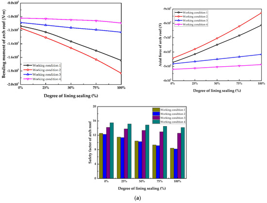

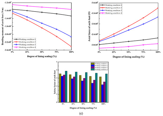

Figure 8.
Internal force diagram and safety factor diagram of the lining structure with different sealing degrees under different working conditions: (a) bending moment, axial force and safety factor of the arch roof; (b) bending moment, axial force and safety factor of the arch waist; (c) bending moment, axial force and safety factor of the arch foot; (d) bending moment, axial force and safety factor of the inverted arch.
4. Analysis of the Influence of the Fault Fracture Zone on the Stability of the Surrounding Rock around a Submarine Tunnel
4.1. Analysis of the Influence of the Fault Fracture Zone on the Displacement of Surrounding Rock
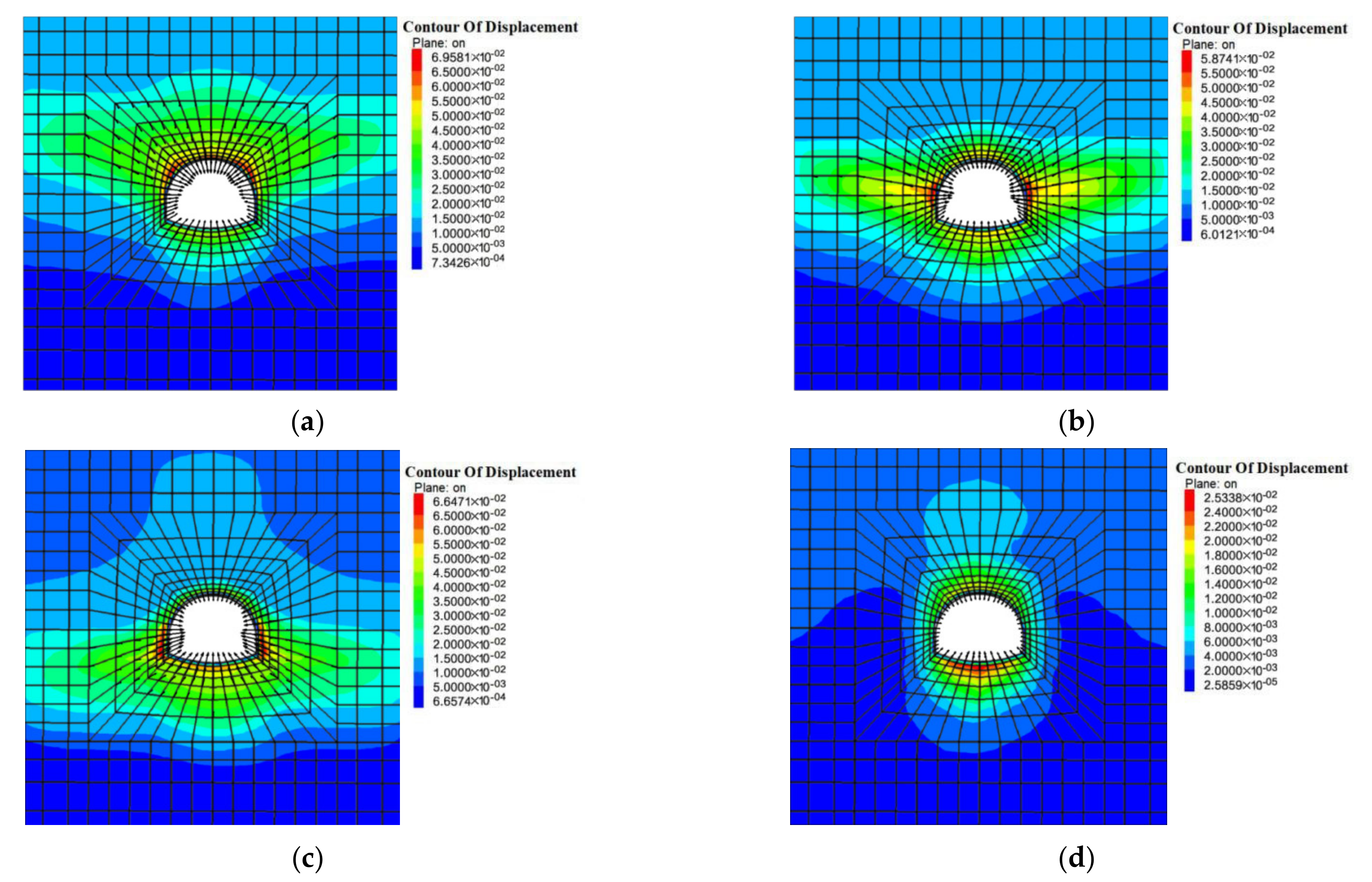
After the excavation of the submarine tunnel, it is particularly important to control the deformation of the rock mass around the cavern. To study the displacement law of the surrounding rock of submarine tunnels under the influence of a fault fracture zone, four kinds of working conditions were simulated using FLAC3D. Figure 9 shows the distribution of surrounding rock displacement distribution under four conditions under the influence of a fault fracture zone.

Figure 9.
Cloud image of the surrounding rock displacement distribution of a submarine tunnel under the influence of a fault fracture zone: (a) Working condition 1; (b) Working condition 2; (c) Working condition 3; (d) Working condition 4.
As shown in Figure 9, the fault fracture zone has a greater impact on the displacement of the rock mass around the submarine tunnel. The surrounding rock with large deformation is mainly concentrated in the fault fracture zone, and the displacement from the tunnel center to the surrounding area gradually decreases. It is worth noting that the maximum displacement of the broken rock in the fault zone in Case 1 and Condition 3 is greater than the maximum displacement of the intermediate rock in the fault zone of the entire submarine tunnel. This is as a result of the uneven disturbance caused by the excavation and support to the fault fracture zone, causing the lining structure under Working conditions 1 and 3 to be heavily biased, and due to the interaction between the supporting structure and the surrounding rock, the deformation of the surrounding rock did not take place evenly.
4.2. Analysis of the Influence of the Fault Fracture Zone on the Plastic Zone
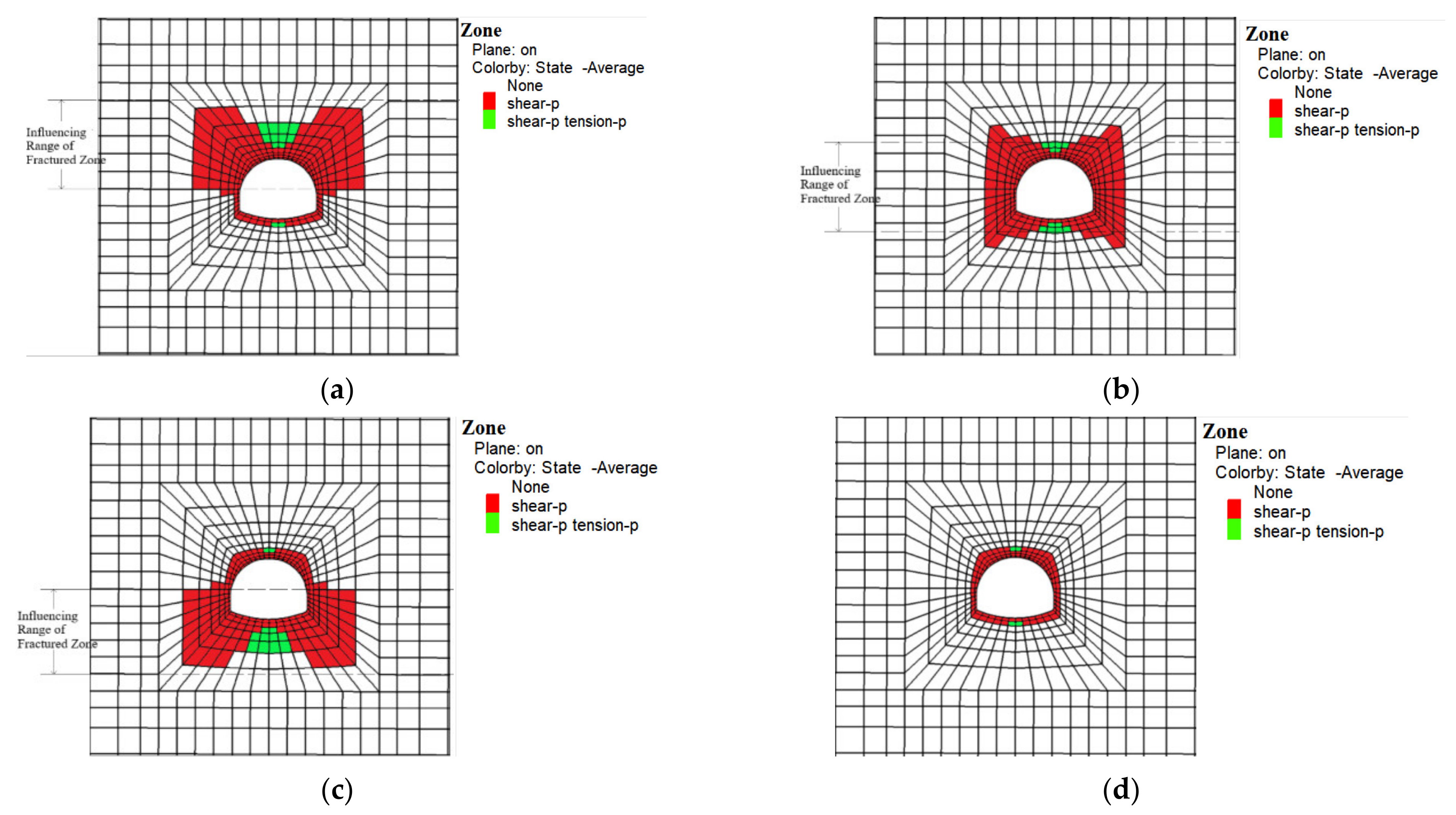
After the excavation of the submarine tunnel, the stress on the surrounding rock is redistributed, causing shear damage or tensile failure of the surrounding rock in local areas. In the surrounding rocks with different permeability, the distribution of the plastic zones must also be understood during the construction of submarine tunnels. Therefore, FLAC3D simulation software was used to calculate the distribution of the plastic zones of the rock mass around the submarine tunnel affected by the fault fracture zone.
As shown in Figure 10, as a result of being affected by the fracture zone, both the arch roof and the inverted arch of the tunnel are subject to tensile damage. When the upper half of the submarine tunnel is located in the fault fracture zone, that is, Working condition 1, the tensile damage area of the vault increases significantly, and the plastic zone of the arch shoulder is more prominent. When the lower half of the submarine tunnel is located in the fault fracture zone, that is, Condition 3, the plastic zone at the arch foot and the inverted arch have a wide distribution range. When it is located in the fault fracture zone, that is, Working condition 2, the plastic area is distributed in a large and uniform manner. Compared with Condition 4, the plastic zone of the tunnel passing through the fault fracture zone is increased in Conditions 1, 2 and 3. The distribution of the above plastic zones is caused by uneven support forces.

Figure 10.
Distribution of the plastic zone in the surrounding rock of a submarine tunnel affected by the fault fracture zone: (a) Working condition 1; (b) Working condition 2; (c) Working condition 3; (d) Working condition 4.
5. Conclusions
This paper mainly analyzes the influence of the fault fracture zone on the stability of the submarine tunnel with respect to the lining structure and the surrounding rock. The main conclusions are as follows:
(1) When the upper half of the submarine tunnel is located in the fault fracture zone, as a result of the obvious bias of the supporting structure, the settlement of the arch top increases significantly, second only to cases where the submarine tunnel is wholly located within the fault. When the lower half of the submarine tunnel is located in the fault fracture zone, the arch foot convergence increases.
(2) As the degree of plugging continues to increase, the bending moments and axial forces of the arch roof, arch waists, arch foot, and inverted arch of the lining structure of the submarine tunnel in the fault fracture zone increase, but the corresponding safety factors decrease. For submarine tunnels under Conditions 1 and 3, some support structures are located within the fault, and the internal forces in this structure are greater than those in other structures. The comparative degrees of internal force at the arch roof under different working conditions is as follows: Working condition 2 > Working condition 1 > Working condition 3 > Working condition 4. Under different working conditions, the comparison of the internal forces at the arch waist and arch foot and the inverted arch is as follows: Working condition 2 > Working condition 3 > Working condition 1 > Working condition 4. There is a negative correlation between the safety factor and internal force.
(3) The surrounding rock with a degree of deformation is mainly concentrated in the fault fracture zone, and the displacement from the tunnel center to the surrounding area gradually decreases. It is worth noting that the maximum displacement of the broken rock in the fault zone in Case 1 and Condition 3 is greater than the maximum displacement of the intermediate rock in the fault zone of the entire submarine tunnel, as a result of the uneven disturbance caused by the excavation and support in the fault fracture zone. At the same time, the tensile damage area of the arch roof in Case 1 is increased, and the plastic zone at the arch shoulder is particularly obvious. The distribution range of the plastic zone at the arch foot and the inverted arch in Case 3 is large and uneven.
Author Contributions
All the authors contributed to publishing this paper. W.F. and G.W. contributed to the formulation of the overarching research goals; C.W. provided language and picture support. All authors have read and agree to the published version of the manuscript.
Funding
This study was supported by the National Natural Science Foundation of China (nos. 51479108).
Acknowledgments
The authors would like to thank the editor and anonymous referees very much for their work on this paper.
Conflicts of Interest
The authors declare no conflict of interest.
References
- Ai, Q. Overview of Underwater Highway Tunnels and Related Technical Issues. Traffic Constr. Manag. 2007, 1, 46–49. [Google Scholar]
- Xu, B.; Li, S.; Li, S.; Zhang, Q. The Relationship between Seepage Volume and Rock Cover Thickness in Subsea Tunnel. Mech. Eng. 2007, 1, 34–37. [Google Scholar]
- Zhou, Y.; Chen, W.; Li, S. Research on Rock Cover Thickness of Submarine Highway tunnel. J. Rock Mech. Eng. 2004, S2, 4704–4708. [Google Scholar]
- Qing, S.; Xie, W.; Gu, W.; Huang, S. Innovation of Key Construction Technology for Kiaochow Bay Submarine Tunnel with Boring and Blast Method. J. Railw. Eng. 2011, 28, 63–69. [Google Scholar]
- Li, P.; Zhang, D.; Wang, M.; Fang, Q.; Li, B. Mechanical Properties of Lining Structure and Its Cross Section Shape Optimization of Subsea Tunnel. China Railw. Sci. 2009, 30, 51–56. [Google Scholar]
- Zhang, P. Model Test Research on the Distribution law of Water Pressure Upon Lining and the stress Characteristics of Lining Structure in Subject to Subsea Tunnel. Master’s Thesis, Beijing Jiaotong University, Beijing, China, 2008. Available online: https://kns.cnki.net/kcms/detail/detail.aspx?dbcode=CMFD&dbname=CMFD2008&filename=2008049740.nh&v=qOIUypyORwBjpg%25mmd2FLSnIdPVU9987KOTqFWh%25mmd2BWFP%25mmd2BH6Eetq9icTTALFBuFW%25mmd2FpU5sMz (accessed on 8 May 2021).
- Li, S.; Song, S.; Li, L.; Zhang, Q.; Wang, K.; Zhou, Y.; Zhang, Q.; Wang, Q. Decelopement on Subsea Tunnel Model Test System for Solid-Fluid Coupling and its Application. J. Rock Mech. Eng. 2013, 32, 883–890. [Google Scholar]
- Wu, J. Research on The Distribution Law of Seepage Field and The Water Pressure Characteristics of Lining Structure in Subject to Underwater Tunnel of weak Surrounding. Master’s Thesis, Beijing Jiaotong University, Beijing, China, 2013. [Google Scholar]
- Wang, X.; Tan, Z. Study on the Characteristics of Water Pressure on the Composite Lining in Underwater Tunnels. Mod. Tunn. Technol. 2015, 52, 89–97. [Google Scholar]
- Wang, Z.; Wang, J.; Zheng, Y.; Zhang, L. Analysis on Stability of Subsea Tunnel in Fault-rupture Zone. Tunn. Constr. 2007, S2, 60–63. [Google Scholar]
- Wang, Q. Formulation and Verification of Grouting Reinforcement Ring for Fault Fracture Zone of Qingdao Subsea Tunnel. Road Traffic Technol. 2018, 34, 165–170. [Google Scholar]
- Qiao, J.; Chen, X.; Li, R. Grouting Waterproof Construction Scheme for Submarine Tunnel through Fault Fracture Zone. Sichuan Cem. 2017, 5, 29, 96. [Google Scholar]
- Noii, N.; Khodadadiana, A.; Wick, T. Bayesian Inversion for Anisotropic Hydraulic Phase-Field Fracture. arXiv 2020, arXiv:2007.16038. [Google Scholar]
- Khodadadian, A.; Noii, N.; Parvizi, M.; Abbaszadeh, M.; Wick, T.; Heitzinger, C. A Bayesian estimation method for variational phase-field fracture problems. Comput. Mechan. 2020, 66, 827–849. [Google Scholar] [CrossRef] [PubMed]
- Wang, J.; Zheng, Y.; Bao, L. Analysis of Seepage Stability of Submarine Tunnels under Localized Fracture Zone Conditions. Tunn. Constr. 2011, 31, 457–462. [Google Scholar]
- Wang, L.; Li, T. Stability Analysis of Pre-grouting Reinforcement of Submarine Tunnel through Fault Fracture Zone. J. Zhengzhou Univ. 2010, 31, 73–77. [Google Scholar]
- Ye, Z.; Zhang, C. Influence of Loose Contact between Tunnel Lining and Surrounding Rock on the Safety of the Tunnel Structure. Symmetry 2020, 12, 1733. [Google Scholar] [CrossRef]
- Zhou, S.; Pan, G.; Luo, X. Assessment on Construction Risks of Sub-sea Tunnels Crossing Fault and Fracture Zones and Countermeasures. Tunn. Constr. 2010, 30, 360–364. [Google Scholar]
- Wang, Z.; Wang, J.; Zheng, Y.; Zhang, L. Limit Analysis of Subsea Tunnel Stability by Finite Element Method in Fault-Rupture Zone with Water Penetration. J. Rock Mech. Eng. 2007, S2, 3751–3755. [Google Scholar]
- Su, J.; Jie, Y.; Niu, X.; Liu, C.; Liu, X. Mechanical Behavior of Tunnel Lining with Cracks at Different Positions. Symmetry 2020, 12, 194. [Google Scholar] [CrossRef] [Green Version]
- Li, G.; Wang, C.; Wang, G.; Xiao, Z.; Wu, X.; Jiang, F. Effect of the Blocking Water and Limiting Discharge and Surrounding Rock Permeability on the Stability of Subsea Tunnel. Geotech. Geol. Eng. 2021, 39, 1365–1380. [Google Scholar] [CrossRef]

Publisher’s Note: MDPI stays neutral with regard to jurisdictional claims in published maps and institutional affiliations. |
© 2021 by the authors. Licensee MDPI, Basel, Switzerland. This article is an open access article distributed under the terms and conditions of the Creative Commons Attribution (CC BY) license (https://creativecommons.org/licenses/by/4.0/).