Article

Node Selection Algorithm for Network Coding in the Mobile Wireless Network

1
Provincial Key Laboratory of Information Coding and Transmission Institute of Mobile Communications, Southwest Jiaotong University Chengdu, Chengdu 610031, China
2
University of Chinese Academy of Sciences, Beijing 100039, China
*
Author to whom correspondence should be addressed.
Symmetry 2021, 13(5), 842; https://doi.org/10.3390/sym13050842
Submission received: 14 February 2021 / Revised: 12 April 2021 / Accepted: 30 April 2021 / Published: 10 May 2021
(This article belongs to the Special Issue Symmetry and Asymmetry in Communications Engineering)

Abstract

:
In the multicast network, network coding has proven to be an effective technique to approach maximum flow capacity. Although network coding has the advantage of improving performance, encoding nodes increases the cost and delay in wireless networks. Therefore, minimizing encoding nodes is of great significance to improve the actual network’s performance under a maximum multicast flow. This paper seeks to achieve partial improvements in the existing selection algorithm of encoding nodes in wireless networks. Firstly, the article gives the condition for an intermediate node to be an encoding node. Secondly, a maximum flow algorithm, which depends on the depth-first search method, is proposed to optimize the search time by selecting the larger augmentation flow in each step. Finally, we construct a random graph model to simulate the wireless network and the maximum multicast flow algorithm to analyze the statistical characteristics of encoding nodes. This paper aims at the optimization to find the minimal number of required coding nodes which means the minimum energy consumption. Meanwhile, the simulations indicate that the curve of coding nodes tends to be a geometric distribution, and that the curve of the maximum flow tends to be symmetric as the network scale and the node covering radius increase.

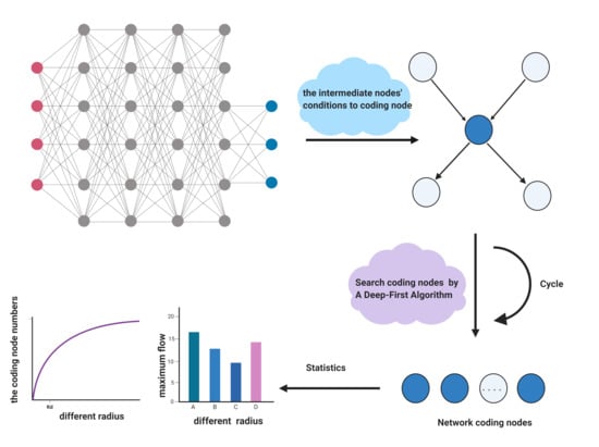
Graphical Abstract

1. Introduction

The concept of network coding was introduced in a seminal paper by Ahlswede [1]. It showed that the network’s transmission ability could be improved markedly. In network coding, network nodes consist of non-encoding nodes and encoding nodes in a multicast network. The non-encoding nodes only forward the copied information, while the encoding nodes encode the received data when it is necessary [2]. In a wireless sensor network, it is composed of a few millions of devices that can be interactive with their surrounding environment by collecting and transferring information. The data packets of sensor nodes, which include temperature, light, sound, and other information, can be only replicated and forwarded regardless of the content correlation between the data or encoded the data packets into one packet. The number of encoding nodes accordingly increases when the network scale expands, which means that more routing devices need to be replaced. Although applying network coding can improve the existing network’s transmission performance, it also brings about high cost and complexity at the nodes performing network coding [3].
Network coding has been applied widely nowadays in, e.g., the mobile ad-hoc network, wireless sensor network, and cognitive radio network [4]. Wireless multi-hop networks such as WLAN, Ad-hoc, sensor networks become popular in recent years. When nodes added or removed by a self-organizing manner in sensor networks, it is very difficult to predict packet loss, node and link failures [5]. Network coding can recover the original data by exploiting the redundant coding stream in the paths. However, network coding increased the load of the sensor node to process the compiled code [6]. They all exploited network coding to improve the wireless network performance. However, the combination of implementation complexity and the network coding capacity wasn’t considered in wireless networks. Therefore, reducing the complexity of network coding is meaningful to decrease the system’s consumption. Meanwhile, the application of disjoint multipath makes network load balanced.
Although network coding plays an important role in wireless networks, there exists a trade-off between the increment of the network coding throughput and network resources in a completely random network. However, the minimum number of required coding nodes is an NP problem for a multicast network, which means that the calculation cannot be expressed in a polynomial of the node numbers [7]. Fragouli et al. show that the number of coding is upper-bounded by N-1 by using the minimal subtree decomposition of a network with two sources and N sinks in the network [8]. Langberg uses a network conversion algorithm to convert the required coding nodes of different complex networks into a simple network. A directed acyclic network proves that the necessary coding nodes are at most h3k2, where h represents the minimum cut from beginning to end, and k represents the number of destination nodes [9]. If network coding is not performed on the link associated with sink nodes, Wu concluded that the network can reach the upper limit of the multicast rate [10]. D. Lun and Bhattad proposed a distributed algorithm to obtain minimum cost multicast [11,12]. Kim used genetic algorithms to minimize the coding nodes in a directed acyclic network and compared two gene coding methods representing chromosomes in blocks to optimize algorithm efficiency [13]. In order to reduce the power consumption for nodes, an optimal network coding based on back pressure routing scheme is used for a massive IOT network [14]. Singh demonstrated the validation of a routing-aware heuristic by an opportunistic network coding mechanism in the multi-hop wireless network [15]. Focusing on dynamic wireless networks, a network coding in the evolutionary network formation is proposed [16]. Those methods can convert the optimization problem of coding nodes into a means of solving linear programming. However, most of the optimization assume the fixed network topologies to validate their algorithms and the statistical characteristics of encoding nodes was not presented.
Network coding is an encoding technology applied to the network layer [17]. Mobile ad hoc networks have increasingly become an important application domain of network coding [18]. When the links between neighboring nodes are established, reliable and effective transmission can be achieved for wired networks. However, links are dynamically connected from nodes’ location in mobile wireless networks, making the old nodes leave, new nodes join rapidly, and connections fail [19]. This situation creates problems in the connectivity of the network. Therefore, a graph model is used to represent the network topology, where nodes are randomly distributed and communicated through a specific transmission protocol. Performing network coding operations on each relay node is not only unnecessary but also uneconomical [20,21]. The traditional method uses the Ford–Fulkerson labelling algorithm to find the maximum flow. The labelling of the Ford–Fulkerson algorithm is to check each vertex once and find an increasable path, which is inefficiency.
To solve the problem of excessive nodes that can cause additional calculation and transmission, this article first discusses selecting the encoding nodes while ensuring the network multicast rate as much as possible in the ad hoc network. In addition, we propose an improved algorithm that makes use of the depth-first search method to find the maximum flow. The proposed algorithm labels each vertex and incoming arc. When selecting a path in each step, the path which contains one label is firstly selected. The path which contains a larger capacity and the shortest path are selected after all the single-labelled paths are completed. It can effectively avoid repeated calculation and improve the efficiency of labels. Different from previous methods, this paper takes into account the energy efficient and the maximum network throughput simultaneously. By choosing appropriately the encoding nodes, it can not only decrease energy consumption but also reduce the times of sending data packets from source node to destination nodes. Finally, we construct the wireless network model diagram, use Matlab to realize the algorithm, analyze the distribution characteristics, and simulate the regular pattern of coding nodes in different network scales and covering radius.

2. Materials and Methods

2.1. The Construction of Network Model

A directed weighted graph is usually used in a wired network to express network topology. Therefore, algebraic network coding can solve network coding’s optimization problem in the directed graph. However, a wireless network cannot only be expressed by a directed weighted graph due to the network’s random topological structure and propagation losses interference [22]. Therefore, this article adopts a random graph model to represent the wireless network.
This random graph can illustrate a network with a control center or a self-organizing network without a center. This article only considers a loop-free topology of the wireless networks without delay and noise. Meanwhile, the nodes’ location stays relatively static, and the network topology remains static at a certain moment. Overall, the topology remains unchanged in a cycle time even though these terminal nodes will change over time. When it comes to the next cycle, the nodes will change and update again.
When a direct link is established between a node and its adjacent nodes, the link has a reliable and effective transmission. A certain amount of energy is required to make a connection for transmitting data packets between wireless terminal nodes [23]. Since the transmission power of a terminal is limited, each terminal has a covering radius, which is determined by the inverse power law model of attenuation and a predetermined threshold of power level for successful reception. Transmission loss causes the signal power to decay with r, where r is the distance between a node and its neighbor nodes in wireless networks [24]. Therefore, a node’s covering radius depends on the transmit power, channel characteristics, and receiver sensitivity, making distance is an essential factor in determining node connectivity. The formula of transmission loss is as follows:
P i j = P 0 ( r d 0 ) α
where Pij is the energy required to establish a link between node i and j; P0 is the energy at the reference distance d 0 ; r is the distance between node i and j; and a represents the channel loss, which is in the range of 2 to 4. Here, it is assumed that each node has the same transmit energy and covering radius r.
In wireless network topology, nodes distributed around a certain node are called adjacent nodes. If adjacent nodes are within the covering radius of a certain node, there is a connecting link between two nodes. Otherwise, there is no connecting link between two nodes [25]. A network graph G with capacity is denoted by G = (V, E), in which V represents a node set {v1, v2, …, vn} and E represents the edge set {e1, e2, …, en}. The maximum transmission rate on each link is called the edge capacity, denoted by Cij, without loss of generality. The link’s actual transmission rate is denoted by fij, which satisfies 0 ≤ fijCij.
As shown in Figure 1a, node i and node j have an intersection area. Since node k is in the intersection area of two nodes, it directly links with node i and node j. The information sent by node i and node j can be directly transmitted to node k without a relay node. However, it can be seen from Figure 1b that there is no common area between the three nodes. For these three nodes, it must be done through a relay node if they want to transmit information to each other.
In general, the wireless network model satisfies the following basic assumptions: ① The source nodes, destination nodes, and relay nodes are randomly distributed in a unit square area; ② The source node S and each relay node i are only connected through a link with a capacity of Csi; ③ Each relay node i is connected with relay node j with Cij, which is the capacity of a directional link from i to j; ④ Each terminal node t has the relay node i through a link with a capacity of Cit; ⑤ The communication channels are orthogonal and symmetric; ⑥ The distance between node i and j is denoted as di,j.

2.2. The Selection Analysis of Encoding Nodes

The critical process of network coding contains two steps. Firstly, the intermediate nodes combine received data through different input links and forward it through its output link. Secondly, the terminal nodes decode the original packets. In contrast to forwarding nodes that can only forward and duplicate input packets, encoding nodes own the coding capabilities. Therefore, we analyze the relationship between the input and output links of the intermediate nodes and discuss the conditions of the encoding nodes.

2.2.1. The Intermediate Node

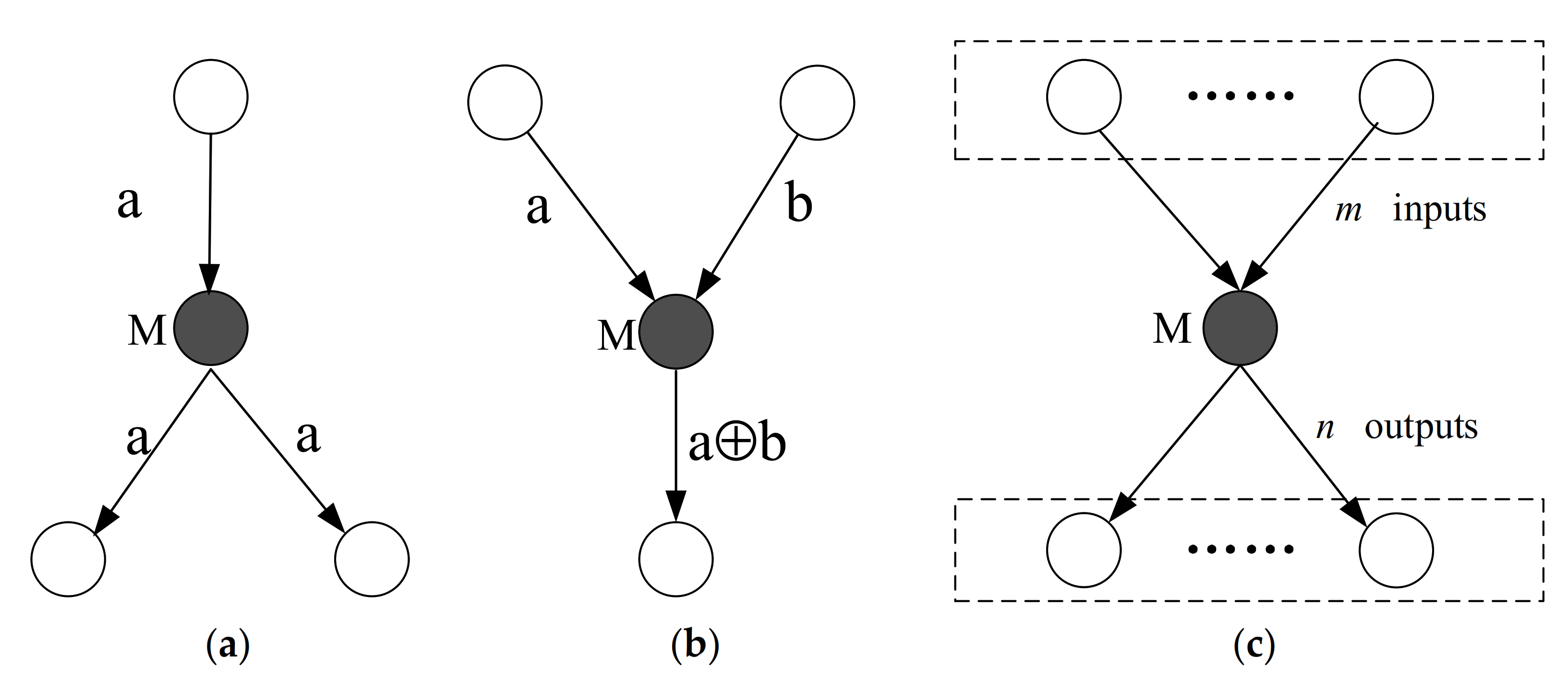
In fact, the intermediate nodes’ topology must be satisfied with one of the structures in the wireless network [26,27,28]. In Figure 2, M represents an intermediate node of network topology, which can encode the received information from its incoming link to create encoded information. When there is one input link and two output links, intermediate nodes act as routers instead of coding nodes in Figure 2a. When there are two input links and one output link, M needs to encode the two received data packets before they can be forwarded in Figure 2b. With the condition that the incoming links are greater than 1, an intermediate node needs to be recognized as an encoding node.
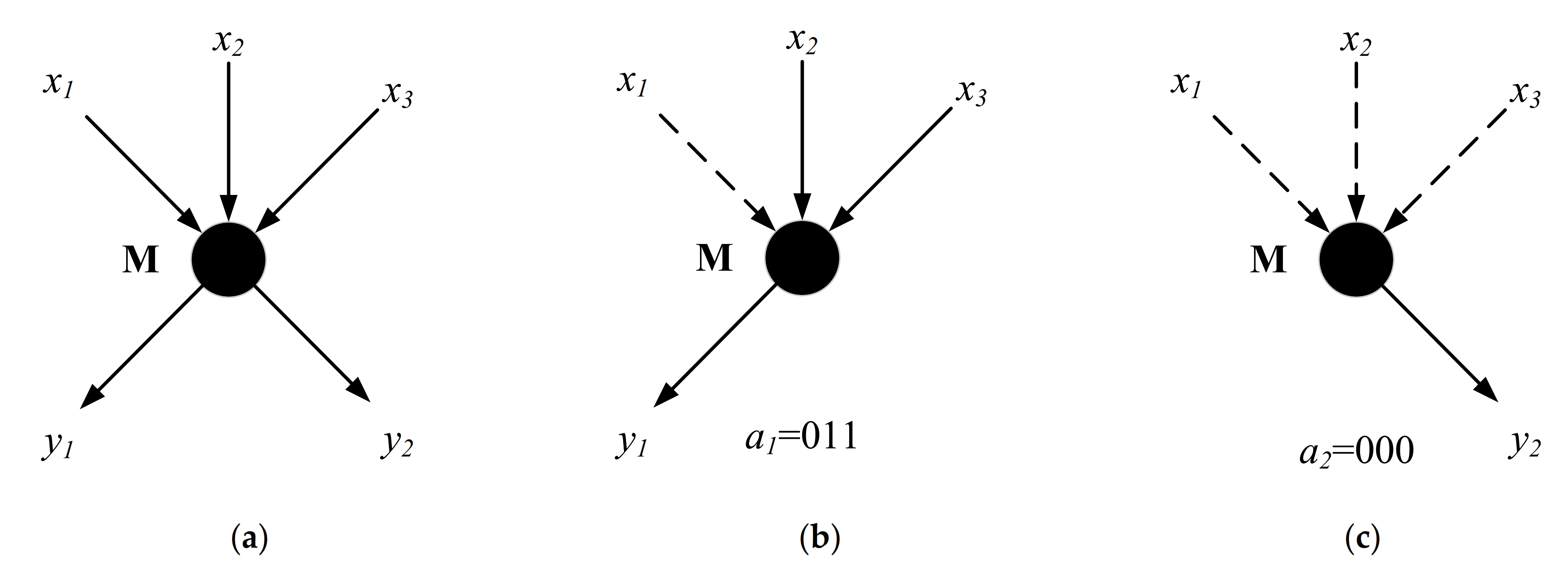
As shown in Figure 2c, the numbers of input and output links toward the intermediate nodes are uncertain. To illustrate the process that the intermediate nodes deal with information, it needs to assign a binary code from the input link to the output links. As shown in Figure 3a, the in-degree of node M is 3, which means that the binary code of the output link is denoted by 3-bit. In Figure 3b, a binary code for the output link y1 is 011, which denotes that the input links x2 and x3 are encoded. In Figure 3c, a coding vector for the output link y2 is 000, which means no data is transmitted. Therefore, it is necessary to calculate the encoding matrix of the input and output link, analyze whether the encoding matrix is full, and finally determine the intermediate node that needs to encode information.
The condition by which to judge whether an intermediate node can convert to an encoding node is summarized as follows. When there are two or more data packets on a certain edge, the edge is called an encoding edge. When there is only one data packet on a certain edge, the edge is called a forwarding side. When a certain output edge of a non-source node is a coding edge, the node is correspondingly a coding node; when all output edges of a certain non-source node are forwarding edges, this node is a forwarding node.

2.2.2. The Encoding Nodes

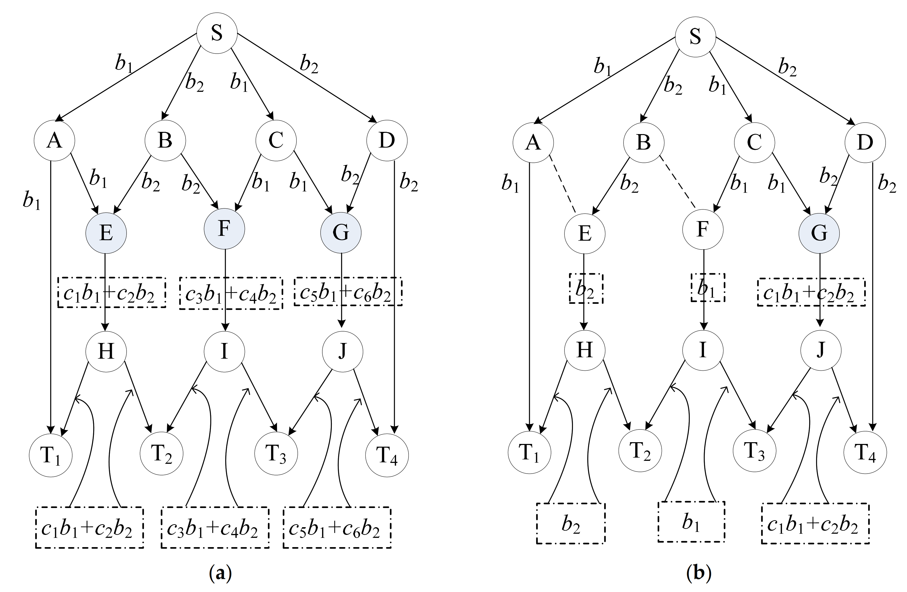
When an edge depends on the combination of two or more data packets, the edge is called an encoding edge [29]. The traditional way of selecting network coding nodes is shown in Figure 4a. If the information packets b1 and b2 can be obtained at the destination nodes T1, T2, T3, and T4, some intermediate nodes need to perform encoding operations. Since the incoming links of nodes E, F, and G comprise two data packets, coding must be performed at those three nodes. At the same time, the total number of data packets, transmitted from the source node to the receiving node, is {6(b1 + b2) + 3[(c1 b1+ c2 b2) + (c3 b1 + c4 b2) + (c5 b1 + c6 b2} in the traditional network. In this case, the traditional network coding schemes still require too many encoding nodes. Therefore, the next step will discuss how to further reduce the number of encoding nodes.
An improved network coding algorithm can be used to search disjoint paths from each source node to each destination node to find encoding nodes from these disjoint paths according to the condition that an intermediate node becomes an encoding node. As illustrated in Figure 4b, the information packets b1 and b2 can be obtained only by encoding at node G for these disjoint paths. The total number of data packets, which are transmitted from source node to destination node, is {9(b1 + b2) +3*(c1 b1 + c2 b2)}. In this way, not only is the maximum multicast rate reached, but the number of nodes participating in network coding can also be minimized. Compared with traditional methods, the improved method can reduce up to one third of the original numbers and data packets.

2.3. The Algorithm of Encoding Nodes

To optimize the number of coding nodes, it is necessary to find the maximum flow route from the source node to the destination node. In this paper, the depth-first search principle is applied based on the existing algorithm, and some improvements are made to the selection process of the augmentation chain. In other words, the feasible flow with larger augmentation capacity and the shorter path is preferentially selected for augmentation in each step.

2.3.1. The Maximum Flow Algorithm Base on Depth-First Search Method

Definition 1.
For a link, its feasible flow is set as fij. If the feasible flow fij is equal to the link’s capacity value cij, this link is saturated. If the feasible flow fij is less than the link’s capacity value cij, this link is unsaturated. If the feasible flow of the link is 0, this link is a zero flow. The sufficient necessity for a feasible flow f to be the maximum is that there is no augmenting chain about f.
Definition 2.
If a directed path from the source node to the destination node is an augmented chain in a network, the following conditions need to be satisfied: ① when the set of all edges are consistent with the direction of the path, each edge needs to satisfy 0 < fij < cij. fij corresponds to the feasible flow of node i and node j on the path. cij corresponds to the capacity of node i and node j on the path; ② when the set of all edges is opposed to the path direction, each edge needs to take the opposite value and satisfy 0 < fij < cij.
Definition 3.
If the incoming terminal of a router is not saturated, but its outgoing terminal is saturated, this router on the augmentation chain is a surplus point in the network diagram.
Definition 4.
When node v is a surplus point, the node v is a quasi-surplus point under the following three conditions: ① in terms of augmented path, there are no other surplus points in front of the upstream; ② the first interconnection link on the augmented path does not reach saturation; ③ there is an augmentable path from the routine to the destination node.
When there is no surplus point on the augmentation path, there is no other augmentable chain along with the augmentation path. When there is a surplus point on the augmented path but no quasi-surplus point, there is no augmentation chain that passes through the first link of the augmentation chain and the path from the surplus point to the end.
The algorithm’s fundamental idea is to calculate the max-flow paths from one source to other destination nodes by the depth-first algorithm, analyze encoding nodes in the paths, and finally perform network coding on network-coded nodes. In order to select minimal encoding nodes, the depth-first maximum stream algorithm includes the five following steps:
The first step: establish a wireless network model. The terminals are randomly distributed in the unit square area [0, 1]2. The covering radius of a node is r. If the node distance is less than r, there is a direct link with a denoted capacity between the two nodes. Otherwise, the two nodes have no direct link, which means that link capacity is 0.
The second step: search for an augmenting chain. The initial flow of each link is 0. Firstly, each node vs. broadcasts a message R to its neighbor nodes. Each message contains a value of sink node and current flow. Secondly, it is necessary to compare the adjacent node flow with node Vs, find the link that contains the largest flow and smallest nodes, define it as the first augmented path, and transmit R. If the chain can be found, it should go to the fourth step to adjust the path. Otherwise, it should find the augmented chain connecting the source node and keeping the remaining flow as the second largest.
The third step: adjust the flow of the expanded paths. Firstly, it is necessary to calculate the remaining flow of all links in the augmentable path. Secondly, we need to compare all links’ remaining flow and take the minimum value as the feasible augmentable path. If each link’s direction is consistent with the direction of the current augmentable path, the remaining flow of the link will decrease by one third. Otherwise, the remaining flow of the link increases by one third. Finally, the remaining flow on the augmentable path is reset.
The fourth step: find other augmentable nodes. Firstly, follow the augmentable chain in the third step, and check the chain’s nodes to judge if there is a quasi-surplus point. If there is a surplus point on the augmented chain, the algorithm will follow that point to find the chain from that point to the destination node. If an augmentable chain from this quasi-surplus point to the destination node is found, the algorithm needs to move to the three steps. If the augmentable chain from this quasi-surplus point to the destination node is not found, the next surplus point is checked until there is no surplus point. When there are no more quasi-surplus points on the augmented chain, return to the second step.
The fifth step: find network coding nodes. After the above steps, we can find the maximum flow path of the whole network, count the flow of each node, and save the information from different incoming links. On the basis of necessary and sufficient conditions for selecting coding nodes, we can find the nodes in the multicast network.
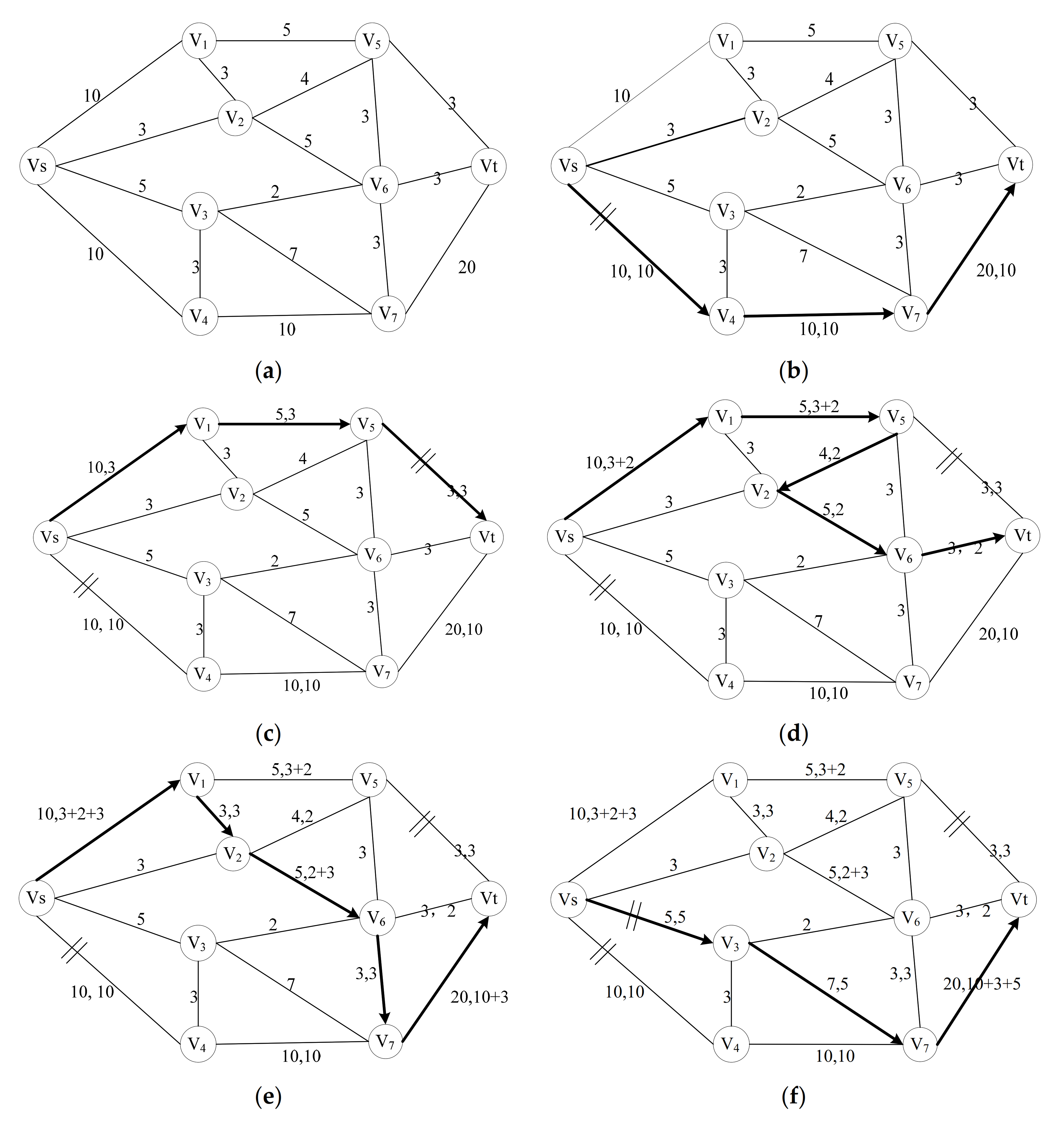
In order to describe the process in detail, this article uses a simple example to find an augmentable path with the largest flow and the smallest number of intermediate nodes in the path. As shown in Figure 5, it mainly includes the following steps: ① with a feasible flow of 10, the first augmentation path is u1: vsv4v7vt in Figure 5b; ② with a feasible flow of 3, the first augmentation path is u2: vs. –v1v5vt in Figure 5c; ③ with a feasible flow of 2, the first augmentation path is u3: vs. –v1v5v2v6vt in Figure 5d; ④ with a feasible flow of 3, the first augmentation path is u4: vsv1v2v6v7vt in Figure 5e; ⑤ with a feasible flow of 5, the first augmentation path is u5: vsv3v7vt in Figure 5f; ⑥ with a feasible flow of 1, the first augmentation path is in Figure 4f; ⑦ with a feasible flow of 2, the first augmentation path is in Figure 5g. The sum feasible flow of each augmented path is 26.

2.3.2. The Process of Computing Network-Codes Nodes

The maximum flow path from the source node to all destination nodes can be found through the above algorithm. Based on all the maximum flow paths, the total feasible flows are calculated by all input links of the intermediate node. If the total feasible flows f satisfies the condition that f ≥ 2, the intermediate node is an encoding node. fi denotes the feasible flow of the incoming link of the intermediate node i. C denotes the transmission capacity of one outgoing link calculated by multiple incoming flows.
To further simplify the above, we consider a wireless network G in which the capacity of each edge is 1 in this article. In the simplified network, coding nodes are determined according to the following criteria: The necessary and sufficient condition for a node to be an encoding node is that it has more than one incoming flow pointing to different destination nodes in the network. Meanwhile, these incoming streams share the same outgoing edge of the node. When two incoming streams directed to different destination nodes share the same outgoing link, the outgoing link is a bottleneck link. In this case, the two streams must be encoded and forwarded to achieve the upper limit of a maximum multicast flow.
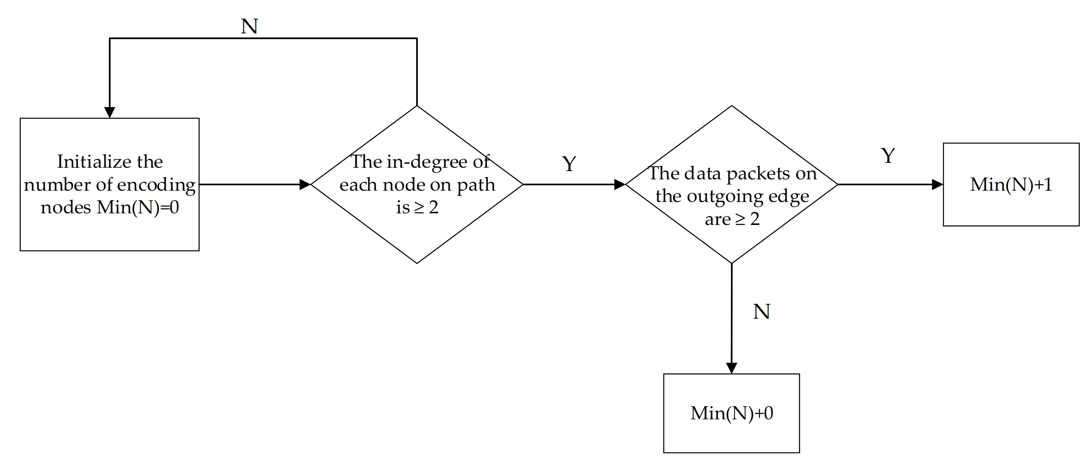
Firstly, a path cluster is established between the source node and all destination nodes by executing the maximum flow algorithm base on depth-first search. Secondly, the encoding node is initialized to 0. The algorithm searches the intermediate nodes on the path cluster, which satisfies the two conditions that the in-degree of the node is greater than 2, and the data packets of its outgoing link simultaneously come from at least two destination nodes. Finally, the number of encoding nodes needs to add one when the intermediate nodes satisfy the above conditions. The calculation process of the encoding node is shown in Figure 6.

3. Results

3.1. The Simulation Result of Different Destinations

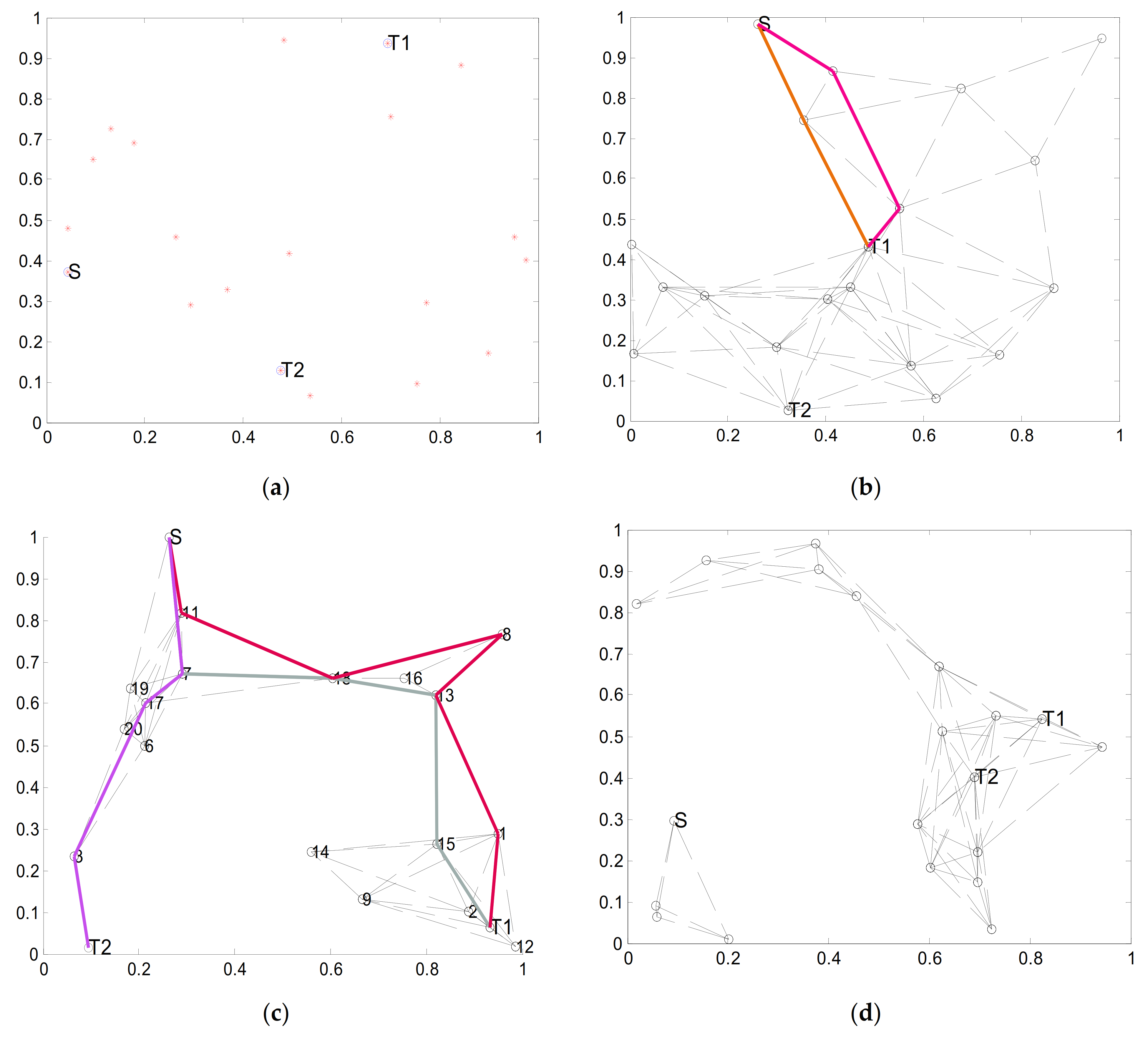
In this paper, the wireless network consists of unfixed nodes without a center. The nodes acted as mobile terminals which can randomly join or exit in the current network. All the terminals will have the same transmission power and thus the same covering radius r. As shown in Figure 7a, this article uses the rand function in Matlab to generate a wireless network in the unit square area. The number of source nodes is 1, and the number of destination nodes is 2. For these intermediate nodes, the distance of each node i can determine whether there is a direct connection link between node j. The network scale is denoted by n. The encoding node selection algorithm is used to find the largest flow path from a source node to destination nodes.
Based on the mobility characteristics of nodes in the wireless network model, it can be assumed that the network topology remains unchanged during the first round of maximum flow search. A new topology will be generated in the next phase of maximum flow search. Figure 7b shows the path from the source point S to one destination node T1; the number of disjoint paths from source node S to destination node T1 is 2. Therefore, the maximum flow is 2 in Figure 7b. Figure 5c shows the path from source node S to two destination nodes T1 and T2. The number of disjoint paths from source node S to destination node T1 is 1; the number of disjoint paths to destination node T2 is 2. Therefore, the maximum multicast flow is 1 in Figure 7c. Figure 7d shows a particular case with no maximum flow path from source node S to two destination nodes T1 and T2. This is due to the fact that there is no direct connection in the process of finding the maximum flow path.

3.2. The Simulation Result of Different Radiuses

As shown in Figure 7, this is an instant simulation of the maximum flow path from a source node to two destination nodes. This section uses numerical simulation to further study the statistical characteristics of encoding nodes, such as the maximum flow and the numbers. For a random graph and a random multicast session, the maximum flow route from the source node to each destination node is regarded as independent and identically distributed. What is more, the edges from different pairs of nodes are independent in a simple network.
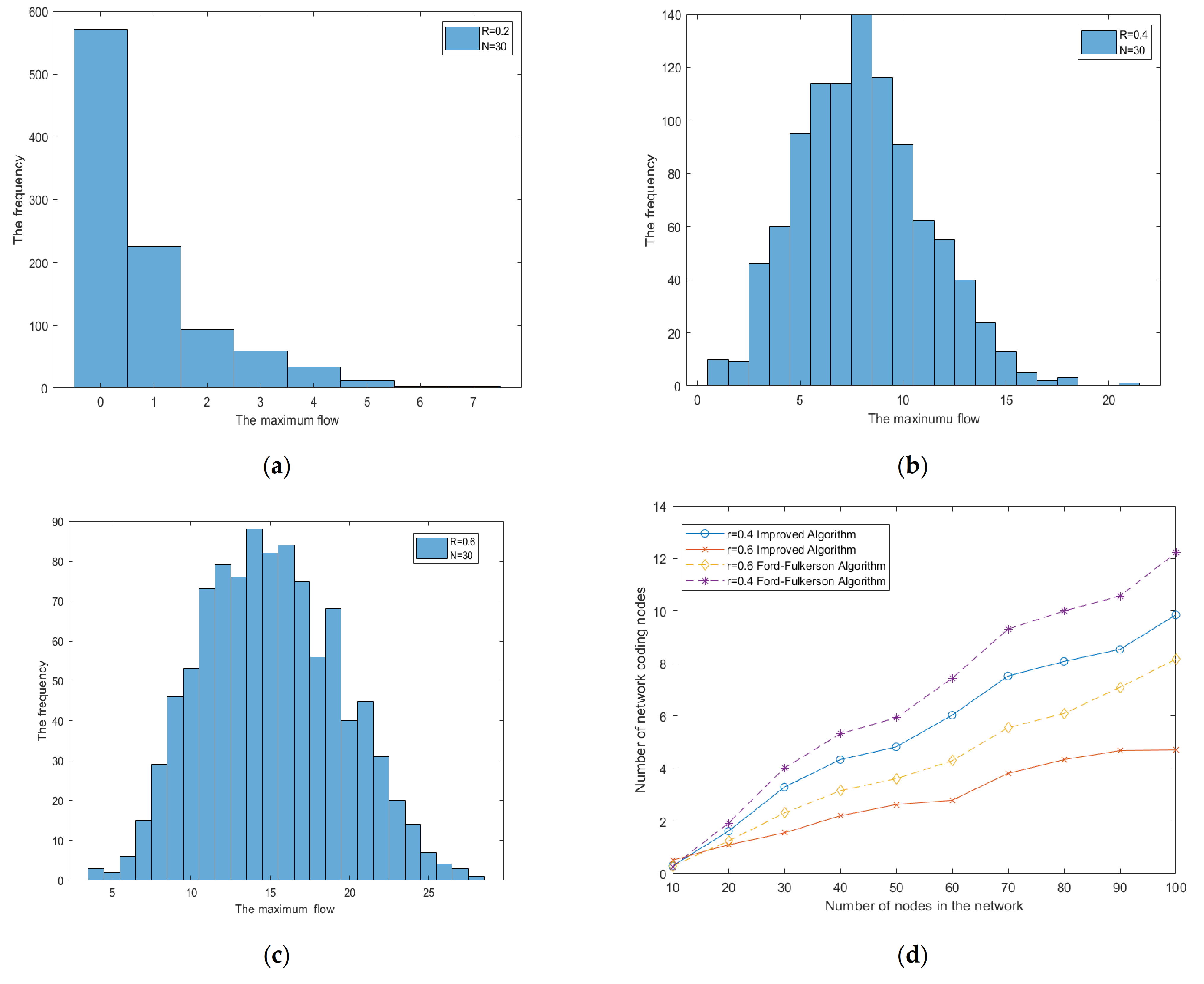
Corresponding to a different r, it shows the end-to-end maximum flow distribution when n is 30 in Figure 8a–c. In order to capture the characteristics more realistically, each parameter simulation was performed 1000 times. It can be seen that the larger the covering radius of node r, the larger the end-to-end average maximum flow. From the simulation results, the end-to-end maximum flow is very close to the geometric distribution when the covering radius of node r is 0.2. This is the reason that the possibility of links between nodes is greatly reduced as the covering radius r becomes smaller, which results in the maximum flow value distributing mainly at 0. While the end-to-end maximum flow is very close to be symmetric when the covering radius r is 0.4 or 0.6, respectively. Simultaneously, the overall square graph tends to incline to the central values. With a covering radius of 0.2, 0.4, and 0.6, Figure 8d respectively shows that the end-to-end maximum flow and the scale of the network keep growing. The maximum flow route passing through each edge is very small as the links increase.
Corresponding to different radius r, Figure 9a–c show the change in encoding node numbers when n is 30. The number of encoding nodes presents a geometric distribution from the simulation results. Comparing with the statistical trend of the encoding nodes, the number of encoding nodes first increases and then decreases toward different covering radiuses. This is why a great majority of paths from a source node to destination nodes are short when r is large, resulting in few bottleneck links. Therefore, a maximum multicast flow can be achieved with only a small amount of network coding. Figure 9d shows that the number of encoding nodes increases as the network scale grows. Meanwhile, the number of coding nodes tends to be flatter as the network scale increases, and the node covering radius is larger. Because the covering radius increases, the available links increase, resulting in a decrease in forming an encoding node. Therefore, it can be concluded that the network code numbers and the node covering radius will affect the maximum stream and the encoding nodes numbers.

4. Discussion

The complexity of the algorithm is analyzed as follows. The network graph vertices are n, and the number of links is m, including finding an augmented path and augmenting flow. Firstly, we calculate the complexity of finding the augmentation path. The network vertices are n, which means that it needs to take at most n steps to search the path from a source node to destination nodes. Therefore, the complexity of using a depth-first search to find the last destination node is O(n). With a total of m links, it takes at most m steps to find the augmented path. Therefore, the algorithm’s complexity in finding the augmented path is O(m*n). Secondly, the flow of each link needs to be modified. The complexity is O(n−1) in the searched augmentation chain process. Finally, the complexity of finding the largest network multicast stream with this algorithm is O(m*n*n). It can be seen that the algorithm is a strong polynomial algorithm.
Compared to the Ford–Fulkerson algorithm, the depth-first algorithm ensures that the largest flow can be found in the network, taking fewer steps to find the augmented path. This is due to the Ford–Fulkerson algorithm not selecting specific nodes in a targeted manner when labeling the next node from the source node. As the calculations of maximum flow paths are fewer, the calculation amount for searching the encoding node numbers is reduced.
There are still many points worthy of research in coding optimization algorithms in the future. The algorithm simulation is carried out under ideal conditions without loops and delays, network packet loss rate, or node memory space, which is different from the real physical scenario. Although the simulation accomplishes the node’s statistical trend and radius in the wireless network, it does not give the upper and lower bounds of the encoding node number. This needs further research. In addition, the improved algorithm is still lacking in time complexity, which requires further research to propose better algorithms.

5. Conclusions

This paper constructs the wireless network topology and discusses how to optimize the encoding nodes, which provides an idea for reducing the complexity of network coding in the wireless network. Then, the maximum flow algorithm based on a depth-first search is proposed, which can avoid blindly searching for the maximum flow and reduce the running time of searching for coding nodes in the overall process. Finally, the article simulates the statistical characteristics of the maximum flow and the number of encoding nodes in the wireless network model. This will provide theoretical guidance for engineering applications.
Since both the scale of the network nodes and the covering radii of the nodes have an effect on the encoding node’s number, our study simulation is summarized as follows: ① the end-to-end maximum flow is very close to very close to be symmetric as the covering radius of the nodes increases. Furthermore, the number of encoding nodes is a geometric distribution. ② The distribution of the number of coding nodes is more to the left of the histogram. ③ The number of encoding nodes first increases and then decreases as the covering radius increases. Moreover, the curve trends more flatly when the covering radius and the scale of the nodes become larger. Therefore, the more network nodes, the greater the gain from network coding. This conclusion supports the whole encoding node selection scheme in the wireless network, and the simulation process proves the feasibility of the scheme.

Author Contributions

D.J. and L.L. thought and planned the total experiments; D.J. and L.L. performed the code programming work, method validation, result discussions, and wrote a majority of sections in this manuscript; D.J. and L.L. supplied recommendations and comments and editing the manuscript. All authors have read and agreed to the published version of the manuscript.

Funding

This research received no external funding.

Acknowledgments

We thank the colleagues in the Provincial Key Laboratory of Information Coding and Transmission Institute of Mobile Communications, Southwest Jiao tong University Chengdu for their assistant in this study.

Conflicts of Interest

The authors declare no conflict of interest.

References

  1. Ahlswede, R.; Cai, N.; Li, S.-Y.R.; Yeung, R.W. Network information flow. IEEE Trans. Inf. Theory 2000, 46, 1204–1216. [Google Scholar] [CrossRef]
  2. Bhadra, S.; Shakkottai, S.; Gupta, P. Min-Cost Selfish Multicast with Network Coding. IEEE Trans. Inf. Theory 2006, 52, 5077–5087. [Google Scholar] [CrossRef]
  3. Zhang, J.; Fan, P. On network coding in wireless ad-hoc networks. Int. J. Ad Hoc Ubiquitous Comput. 2007, 2, 140. [Google Scholar] [CrossRef]
  4. Huang, J.; Xing, C.; Chang, Z. Multi-hop D2D Communications with Network Coding: From a Performance Perspective. IEEE Trans. Veh. Technol. 2019, 68, 2270–2282. [Google Scholar] [CrossRef] [Green Version]
  5. Liu, Q.; Feng, G.; Guo, Y. A Framework of Joint Scheduling and Network Coding for Real-Time Traffic with Diverse Delay Constraints. Wirel. Pers. Commun. 2017, 97, 4855–4876. [Google Scholar] [CrossRef]
  6. Fan, Y.; Jiang, Y.; Zhu, H.; Chen, J.; Shen, X.S. Network Coding Based Privacy Preservation against Traffic Analysis in Multi-Hop Wireless Networks. IEEE Trans. Wirel. Commun. 2011, 10, 834–843. [Google Scholar] [CrossRef]
  7. Jaggi, S.; Sanders, P.; Chou, P.A.; Effros, M.; Tolhuizen, L.M. Polynomial time algorithms for multicast network code construction. IEEE Trans. Inf. Theory, 2005, 51, 1973–1982. [Google Scholar] [CrossRef] [Green Version]
  8. Fragouli, C.; Soljanin, E. Information flow decomposition for network coding. IEEE Trans. Inf. Theory 2006, 52, 829–848. [Google Scholar] [CrossRef] [Green Version]
  9. Langberg, M.; Sprintson, A.; Bruck, J. The encoding complexity of network coding. IEEE Int. Trans. Inf. Theory 2006, 52, 2386–2397. [Google Scholar] [CrossRef] [Green Version]
  10. Wu, Y.; Chou, P.; Kung, S.-Y. Minimum-Energy Multicast in Mobile Ad Hoc Networks Using Network Coding. IEEE Trans. Commun. 2005, 53, 1906–1918. [Google Scholar] [CrossRef]
  11. Li, Y.; Wang, J.; Zhang, S.; Bao, Z.; Wang, J. Efficient Coastal Communications with Sparse Network Coding. IEEE Netw. 2018, 32, 122–128. [Google Scholar] [CrossRef]
  12. Bhattad, K.; Ratnakar, N.; Koetter, R.; Narayanan, K. Minimal network coding for multicast. In Proceedings of the International Symposium on Information Theory 2005, ISIT 2005, Adelaide, SA, Australia, 4–9 September 2005; pp. 1730–1734. [Google Scholar]
  13. Kim, M.; Medard, M. Algebraic Network Coding Approach to Deterministic Wireless Relay Networks. In Proceedings of the 2010 48th Annual Allerton Conference on Communication, Control, and Computing (Allerton), Institute of Electrical and Electronics Engineers, Monticello, IL, USA, 29 September–1 October 2010; pp. 1518–1525. [Google Scholar]
  14. Malathy, S.; Porkodi, V.; Sampathkumar, A.; Hindia, M.H.D.N.; Dimyati, K.; Tilwari, V.; Qamar, F.; Amiri, I.S. An optimal network coding based backpressure routing approach for massive IoT network. Wirel. Netw. 2020, 26, 3657–3674. [Google Scholar] [CrossRef]
  15. Kwon, M.; Hyunggon, P. Network coding based evolutionary network formation for dynamic wireless net-works. IEEE Trans. Mob. Comput. 2018, 18, 1316–1329. [Google Scholar] [CrossRef] [Green Version]
  16. Singh, A.; Nagaraju, A. Heuristic-based opportunistic network coding at potential relays in multi-hop wireless networks. Int. J. Comput. Appl. 2020, 1–12. [Google Scholar] [CrossRef]
  17. Zhao, J.; Yang, F.; Zhang, Q.; Zhang, Z.; Zhang, F. LION: Layered Overlay Multicast with Network Coding. IEEE Trans. Multimed. 2006, 8, 1021–1032. [Google Scholar] [CrossRef]
  18. Chen, P.; Xie, Z.; Fang, Y.; Chen, Z.; Mumtaz, S.; Rodrigues, J.J.P.C. Physical-Layer Network Coding: An Efficient Technique for Wireless Communications. IEEE Netw. 2020, 34, 270–276. [Google Scholar] [CrossRef] [Green Version]
  19. Nazer, B.; Gastpar, M. Reliable Physical Layer Network Coding. Proc. IEEE 2011, 99, 438–460. [Google Scholar] [CrossRef] [Green Version]
  20. Ho, T.; Medard, M.; Koetter, R.; Karger, D.; Effros, M.; Shi, J.; Leong, B. A Random Linear Network Coding Approach to Multicast. IEEE Trans. Inf. Theory 2006, 52, 4413–4430. [Google Scholar] [CrossRef] [Green Version]
  21. Koetter, R.; Médard, M. An algebraic approach to network coding. IEEE/ACM Trans. Netw. 2003, 11, 782–795. [Google Scholar] [CrossRef] [Green Version]
  22. Ho, T.; Koetter, R.; Edard, M.M.; Karger, D.R.; Effros, M. The benefits of coding over routing in a randomized setting. In Proceedings of the IEEE International Symposium on Information Theory 2003, Yokohama, Japan, 29 June–4 July 2003; p. 442. [Google Scholar]
  23. Zhang, J.; Fan, P.; Letaief, B.K. Network Coding for Efficient Multicast Routing in Wireless Ad-hoc Networks. IEEE Trans. Commun. 2008, 56, 598–607. [Google Scholar] [CrossRef]
  24. Chen, S.; Zhao, C.; Wu, M.; Sun, Z.; Zhang, H.; Leung, V.C. Compressive network coding for wireless sensor networks: Spatio-temporal coding and optimization design. Comput. Netw. 2016, 108, 345–356. [Google Scholar] [CrossRef]
  25. Effros, M.; El Rouayheb, S.; Langberg, M. An equivalence between network coding and index coding. IEEE Int. Symp. Inf. Theory 2015, 61, 967–971. [Google Scholar] [CrossRef]
  26. Naeem, A.; Rehmani, M.H.; Saleem, Y.; Rashid, I.; Crespi, N. Network Coding in Cognitive Radio Networks: A Comprehensive Survey. IEEE Commun. Surv. Tutor. 2017, 19, 1945–1973. [Google Scholar] [CrossRef] [Green Version]
  27. Cai, N.; Chan, T. Theory of Secure Network Coding. Proc. IEEE 2011, 99, 421–437. [Google Scholar]
  28. Jiang, D.; Xu, Z.; Li, W.; Chen, Z. Network coding-based energy-efficient multicast routing algorithm for multi-hop wireless networks. J. Syst. Softw. 2015, 104, 152–165. [Google Scholar] [CrossRef]
  29. Xu, G.; Chen, X.-B.; Li, J.; Wang, C.; Yang, Y.-X.; Li, Z. Network coding for quantum cooperative multicast. Quantum Inf. Process. 2015, 14, 4297–4322. [Google Scholar] [CrossRef]
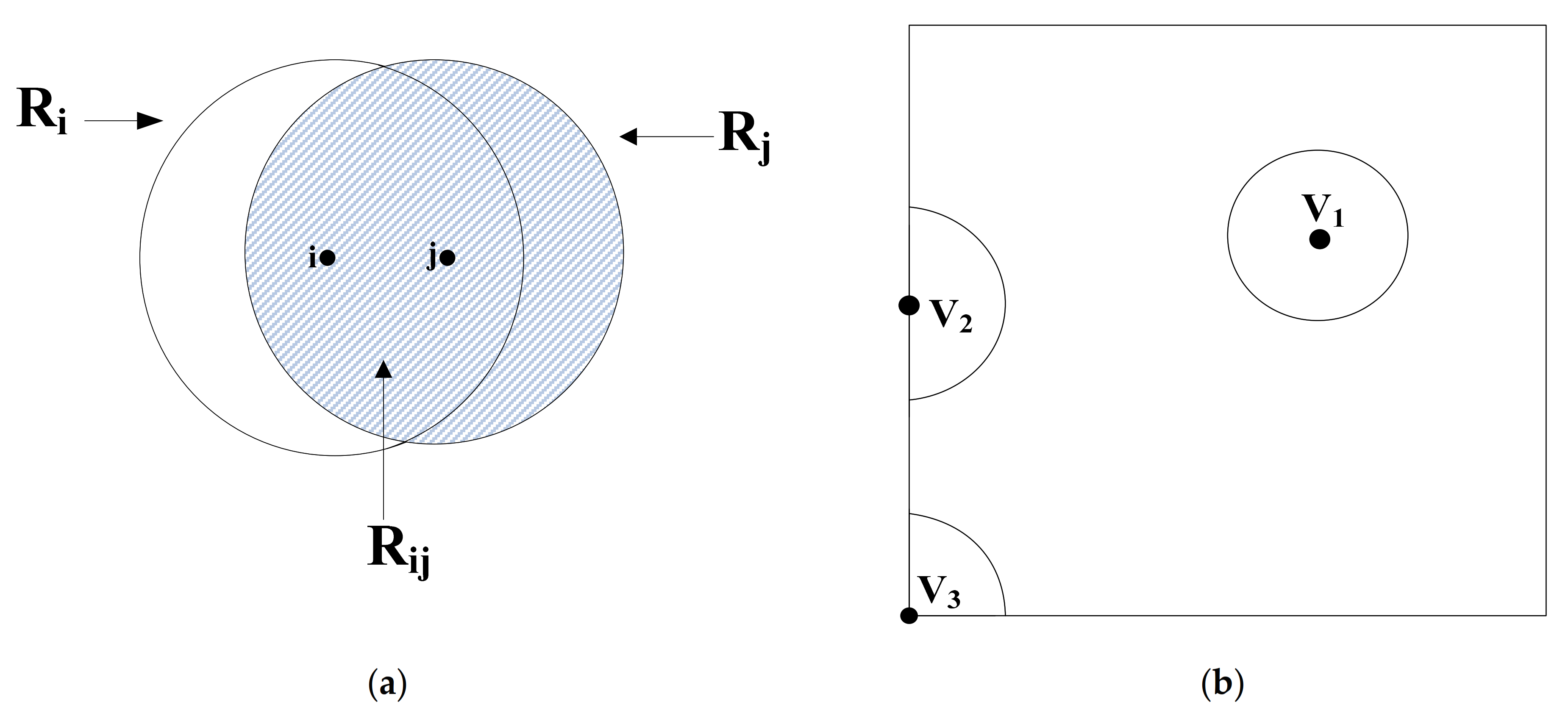
Figure 1. (a) The intersection area of two nodes; (b) The distribution of nodes in a unit area.
Symmetry 13 00842 g001
Figure 2. (a) an intermediate node with one input link and two output links; (b) an intermediate node with two input links and one output links; (c) an intermediate node with m input links and n output links.
Symmetry 13 00842 g002
Figure 3. (a) The encoding matrix of the input and output link; (b) A binary code for the output link y1; (c) A binary code for the output link y2.
Symmetry 13 00842 g003
Figure 4. (a) The node selection method of traditional network; (b) the node selection method of improved network.
Symmetry 13 00842 g004
Figure 5. (a) The original network diagram; (b) The first augmented chain; (c) The second augmented chain; (d) The third augmented chain; (e) The fourth augmented chain; (f) The fifth augmented chain; (g) The sixth augmented chain; (h) The seventh augmented chain.
Symmetry 13 00842 g005aSymmetry 13 00842 g005b
Figure 6. The process of computing network encoding nodes.
Symmetry 13 00842 g006
Figure 7. (a) Random graph in the wireless network; (b) Maximum flow path from a source to a terminal; (c) Maximum flow path from source to two terminals; (d) No maximum flow path from source node to two terminals.
Symmetry 13 00842 g007
Figure 8. (a) A statistic of the maximum flow when radius r is 0.2; (b) A statistic of the maximum flow when radius r is 0.4; (c) A statistic of the maximum flow when radius r is 0.6; (d) A comparison of the maximum flow in different algorithm.
Symmetry 13 00842 g008
Figure 9. (a) A statistic of the coding node numbers when radius r is 0.2; (b) A statistic of the coding node numbers when radius r is 0.4; (c) A statistic of the coding node numbers when radius r is 0.6; (d) A comparison of the maximum flow in different radiuses.
Symmetry 13 00842 g009
Publisher’s Note: MDPI stays neutral with regard to jurisdictional claims in published maps and institutional affiliations.