
Influence of Cairo Metro Tunnel Excavation on Pile Deep Foundation of the Adjacent Underground Structures: Numerical Study


Abstract
1. Introduction
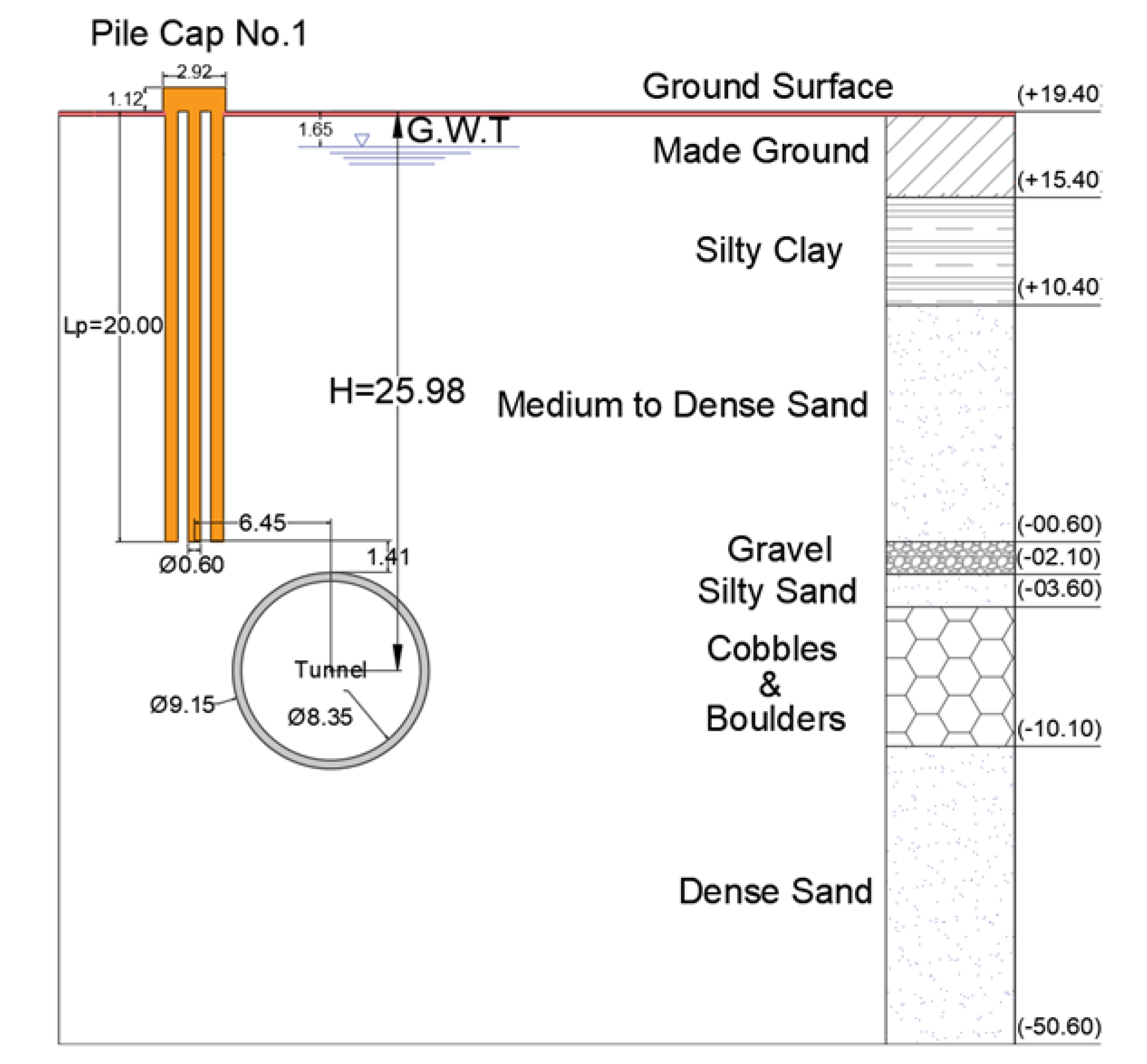
2. Case Study
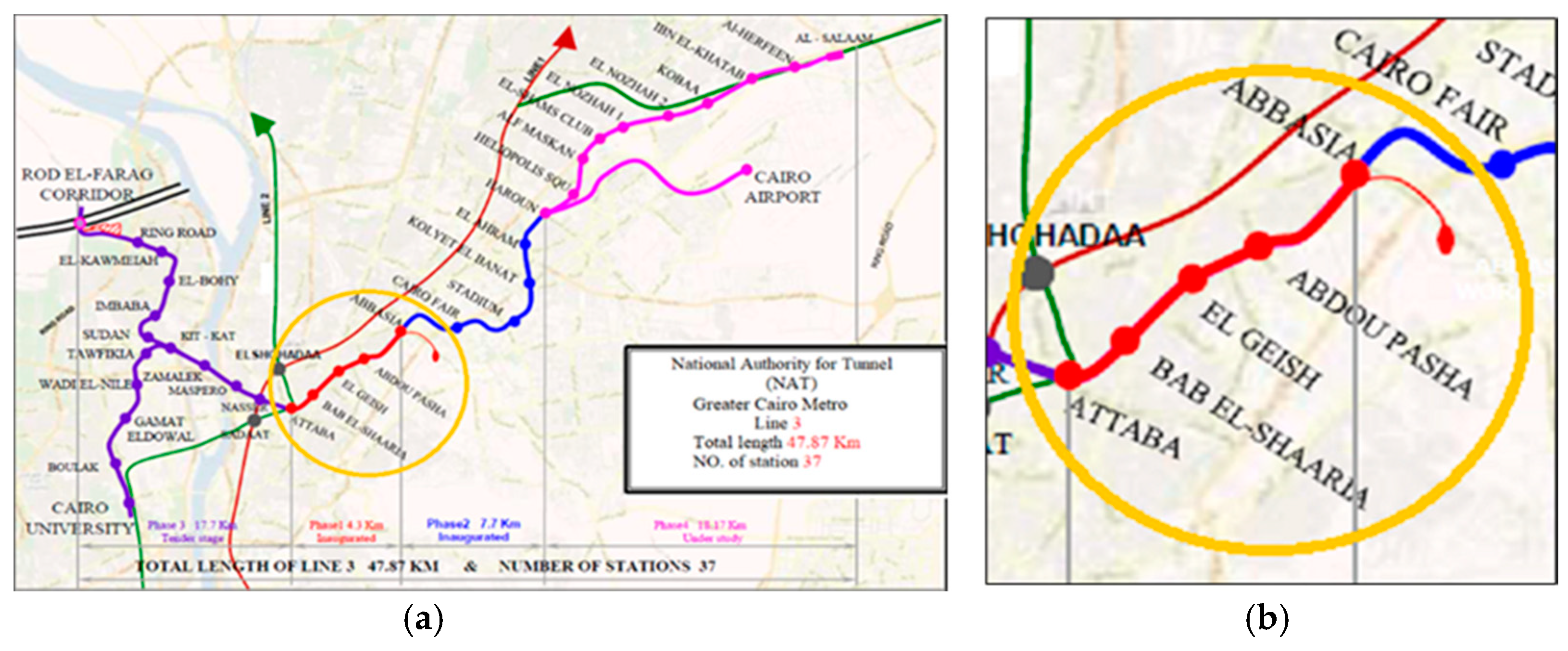
2.1. Greater Cairo Metro-Line 3 Phase-1
2.2. Soil Conditions
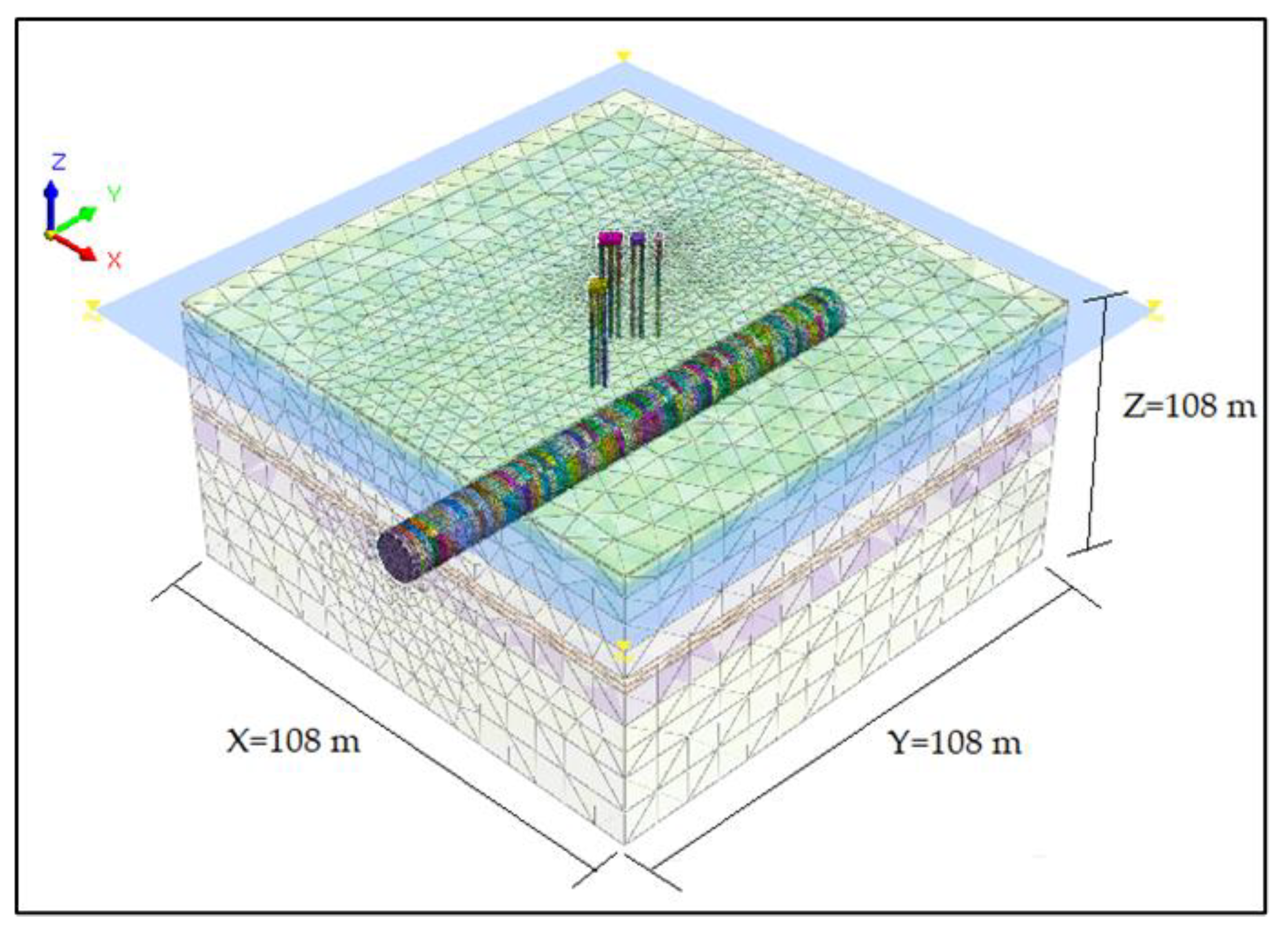
3. Finite Element Modelling
3.1. Numerical Model
3.2. Constitutive Models and Material Parameters
3.3. Numerical Analysis Procedure
- The initial stage set up the initial stress and boundary conditions at-rest earth pressure coefficient of 0.5.
- The first stage starts with changing the properties of the piles to concrete material as soil material replacement. At this stage, the caps are activated.
- The second stage includes applying the building loads to pile caps using eight incremental loadings. At this stage, the displacements of the initial and first stages of analysis were reset to zero in order to facilitate the study of the influence of shield tunneling on pile cap behavior.
- The third stage simulates the advancement of the tunnel and the excavation of the first ring and replaced it with the shield every 3 m. The drilling pressure and shield external pressure are activated.
- Stages from 4 to 6: shield advancement, application of the drilling pressure and the shield external pressure, erecting the first ring of the segment inside the shield and applying the jacking force on it.
- Stages from 7 to 10: Erecting four rings behind the shield and applying the segment external pressure.
- Stage 11: erecting the next ring and the grout is considered hardened by changing the material properties.
- Stages from 12 to 46: Repeat stages (3–7) and continue digging until all segments are completed.
4. Verification of the Numerical Model
5. Numerical Results and Discussion
5.1. Influence of the Tunnel Excavation on the Piles Caps Foundations
5.2. Response of an Existing Pile Cap Foundation (PC1) to Tunneling-Induced Ground Movements with Different Construction Stages
5.3. Parametric Studies
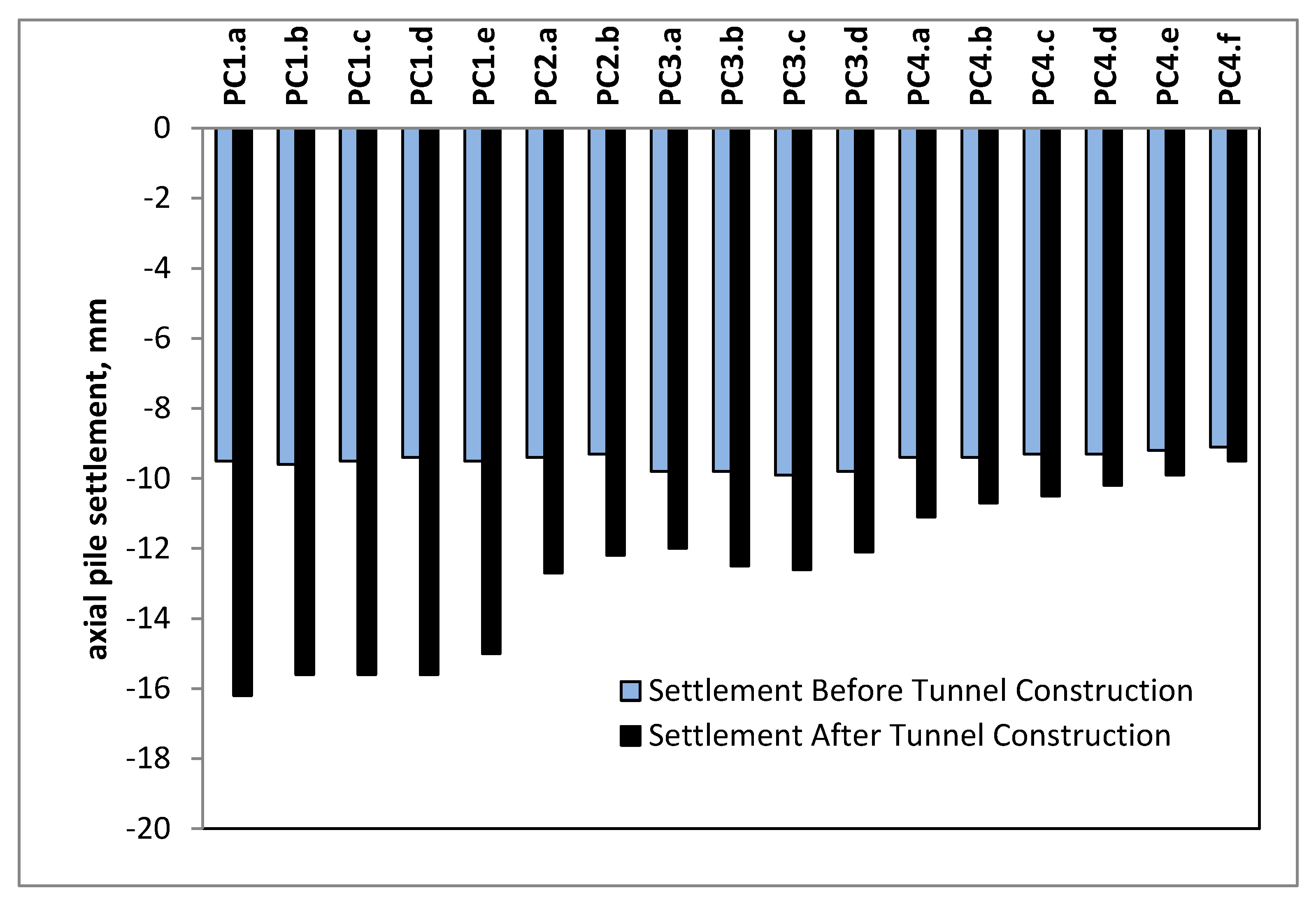
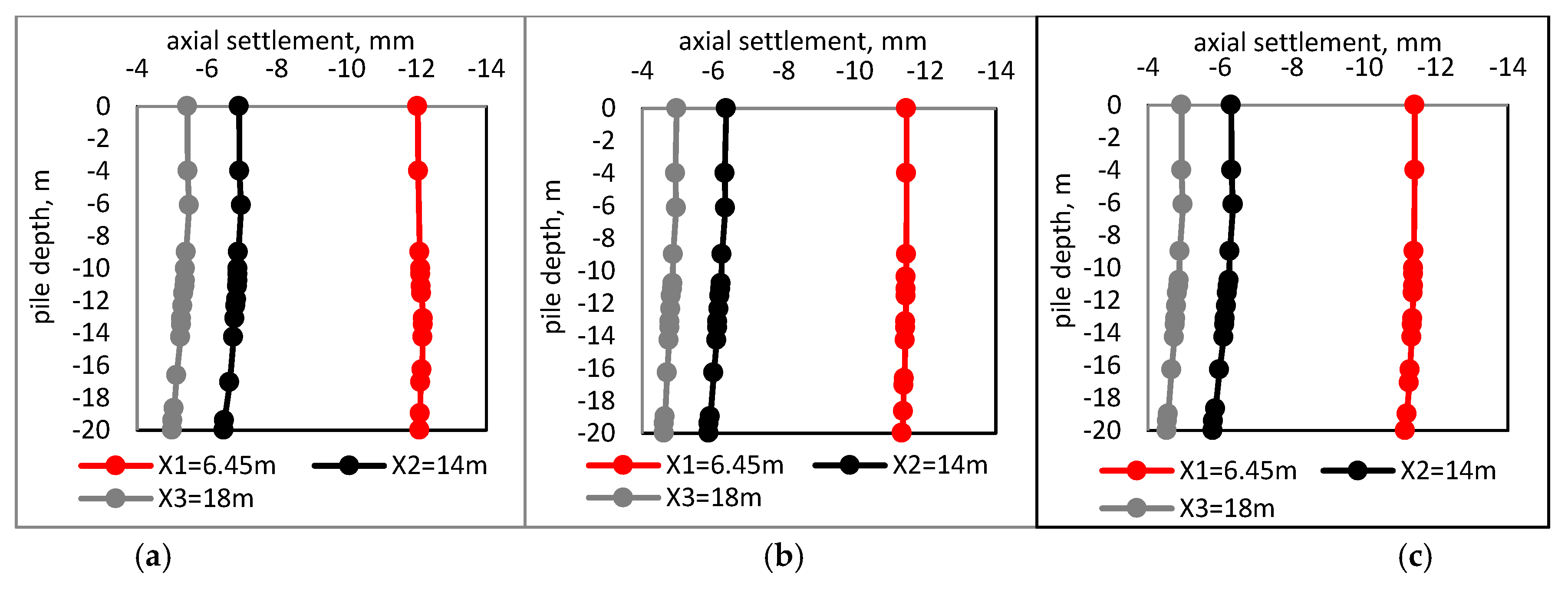
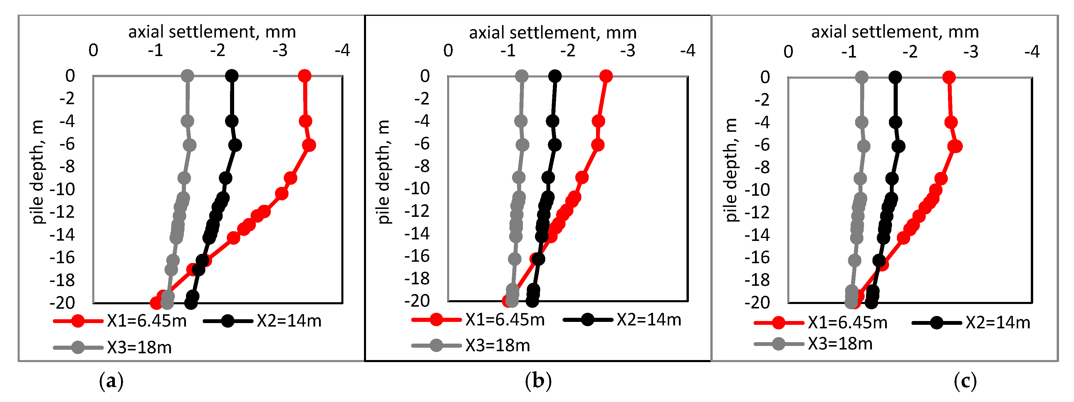
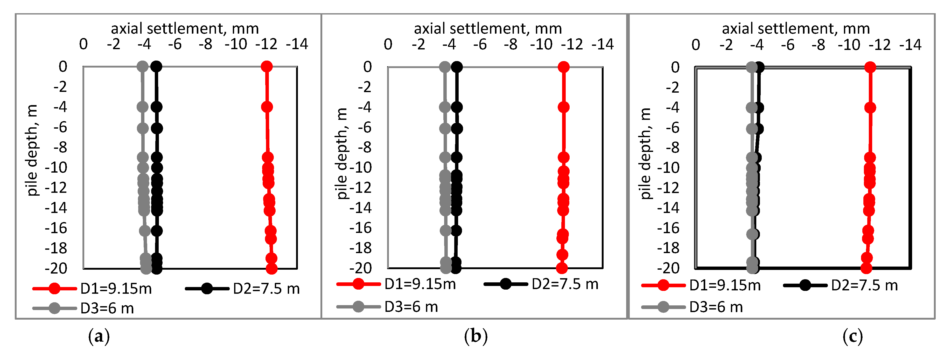
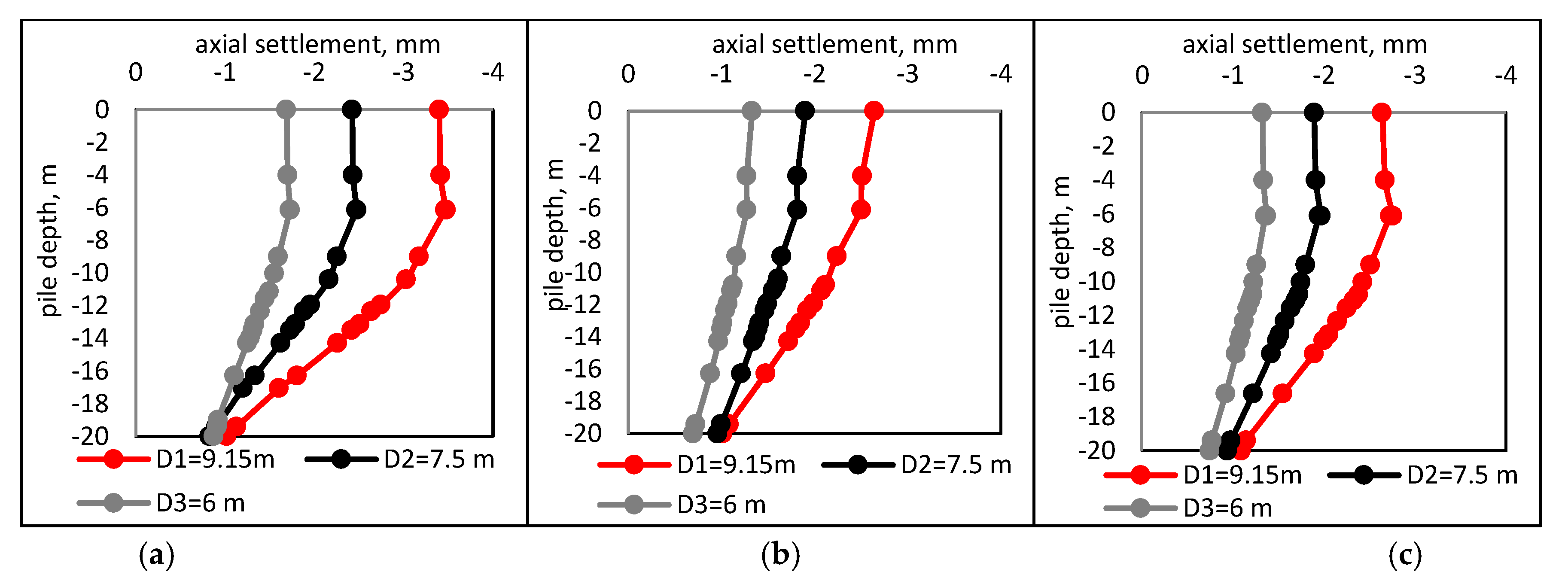
5.3.1. Axial Settlement of the Piles
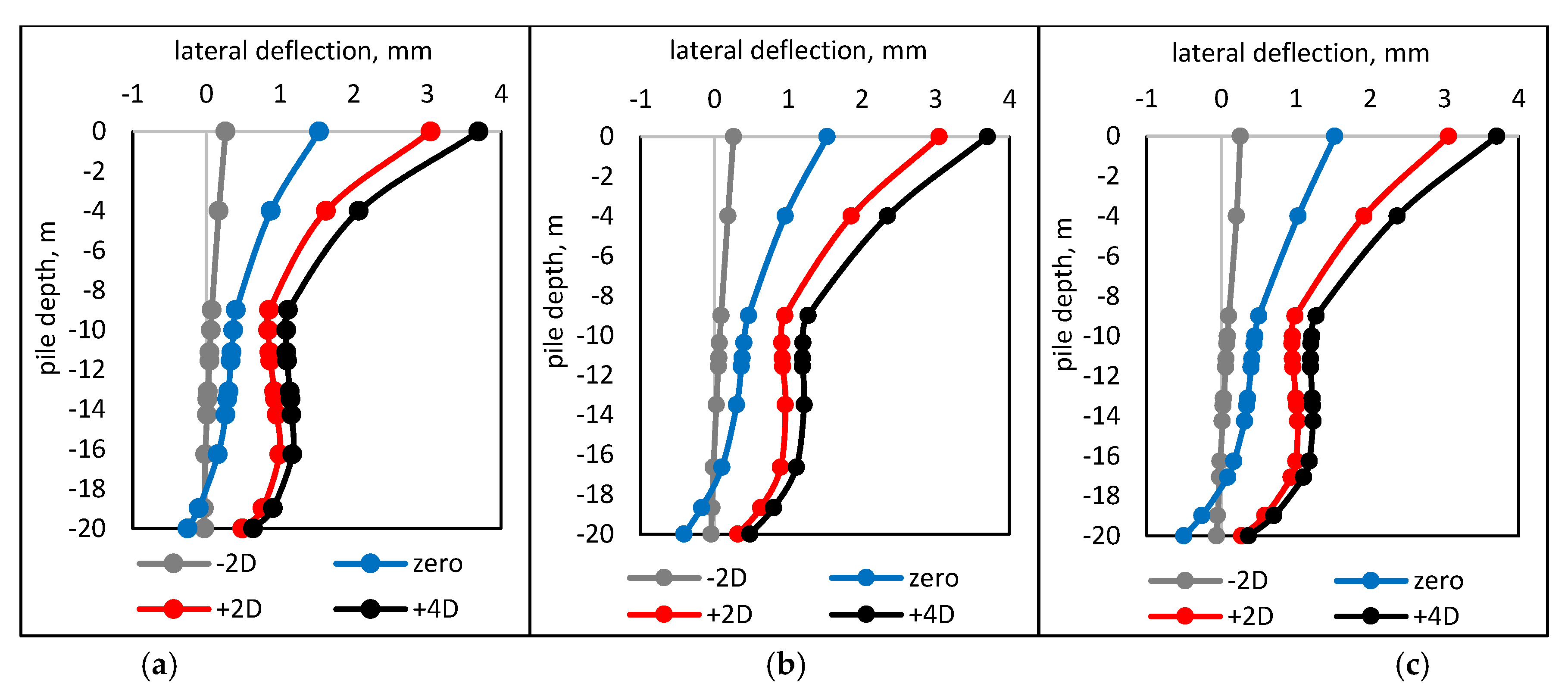
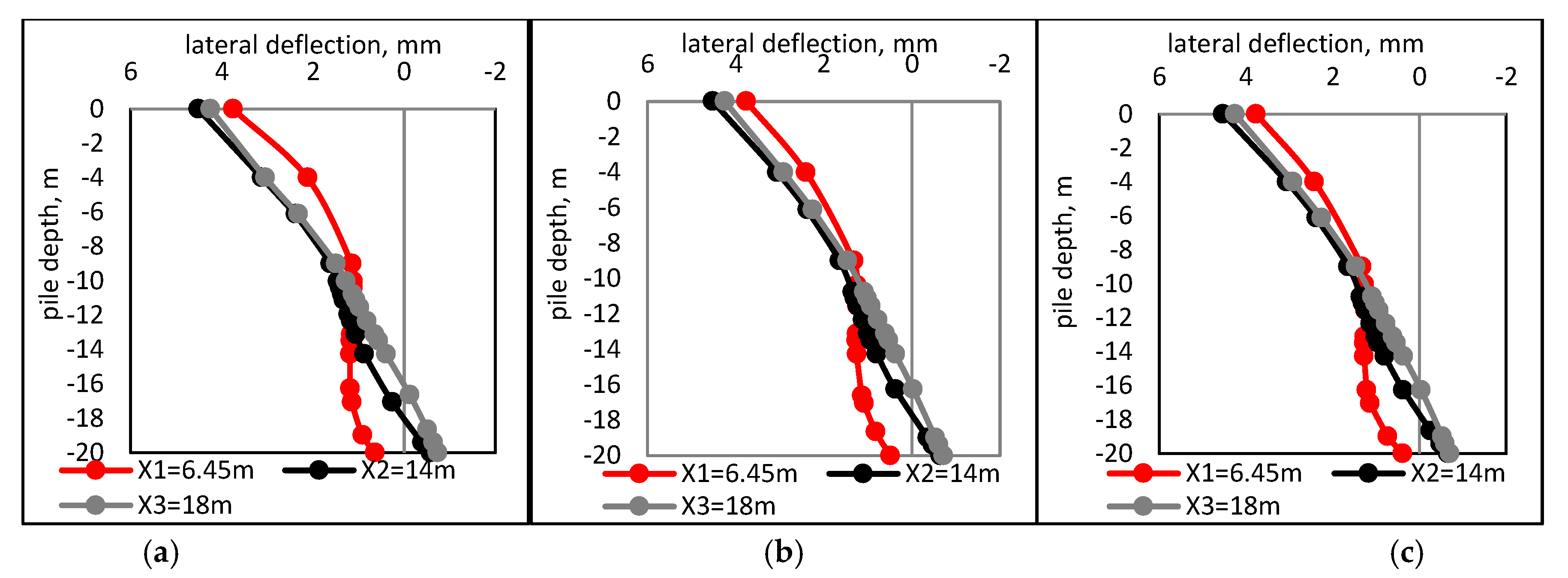
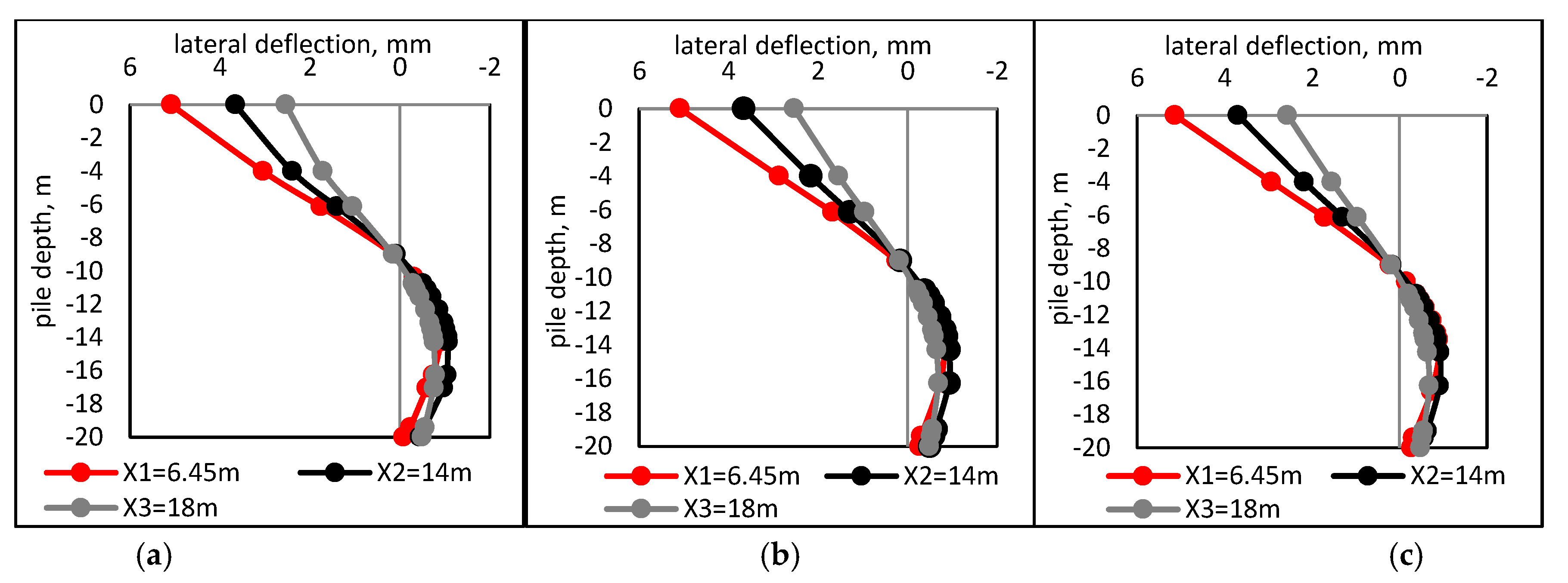
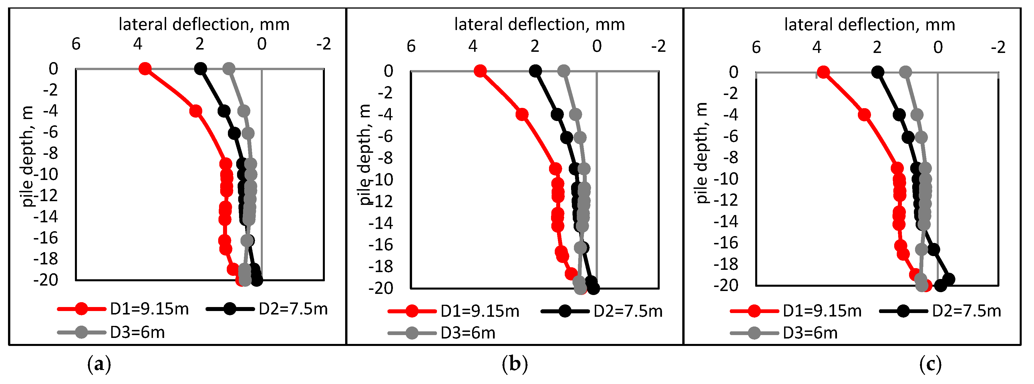
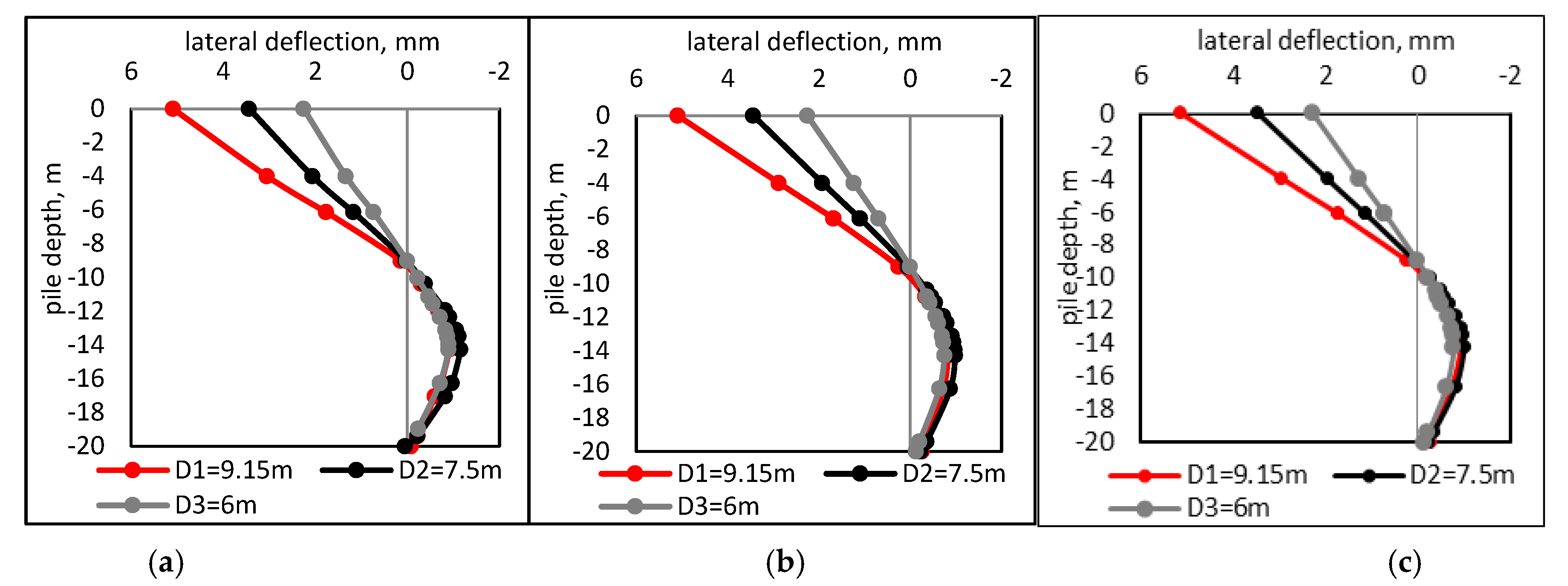
5.3.2. Lateral Deflection of the Piles
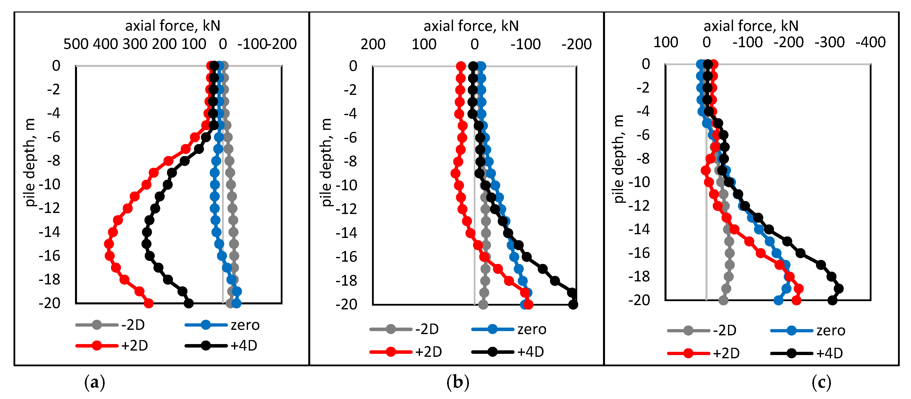
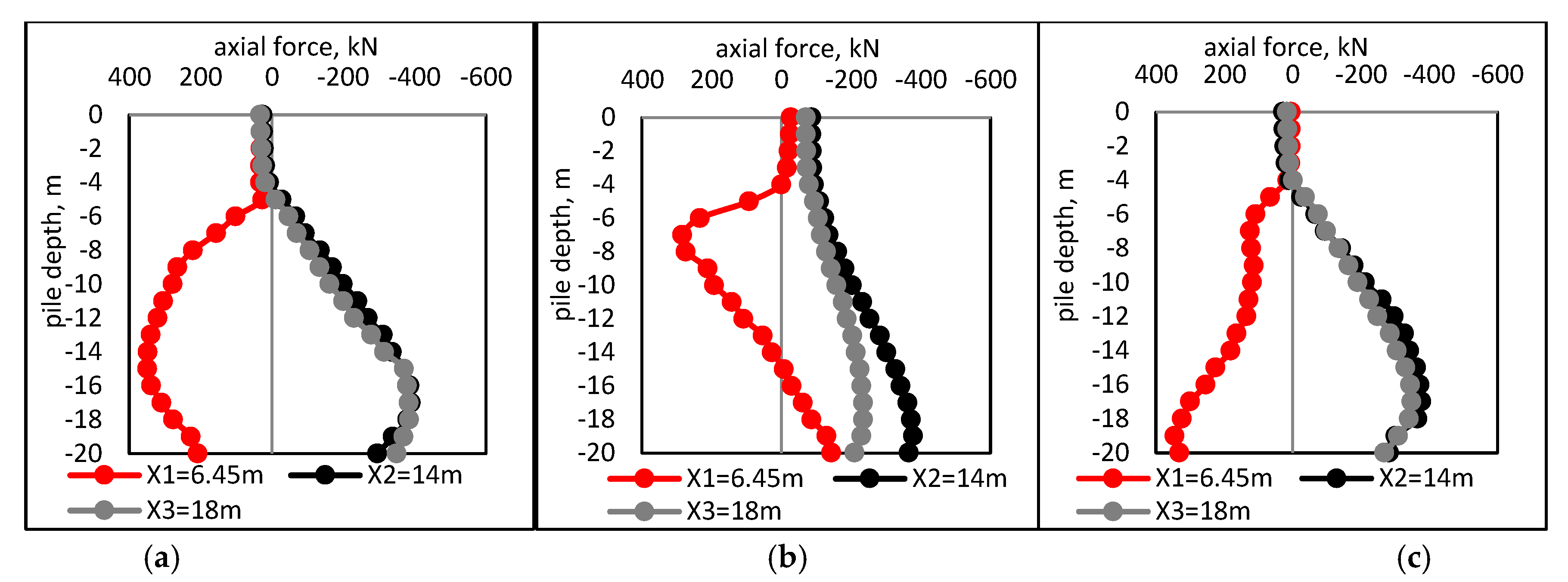
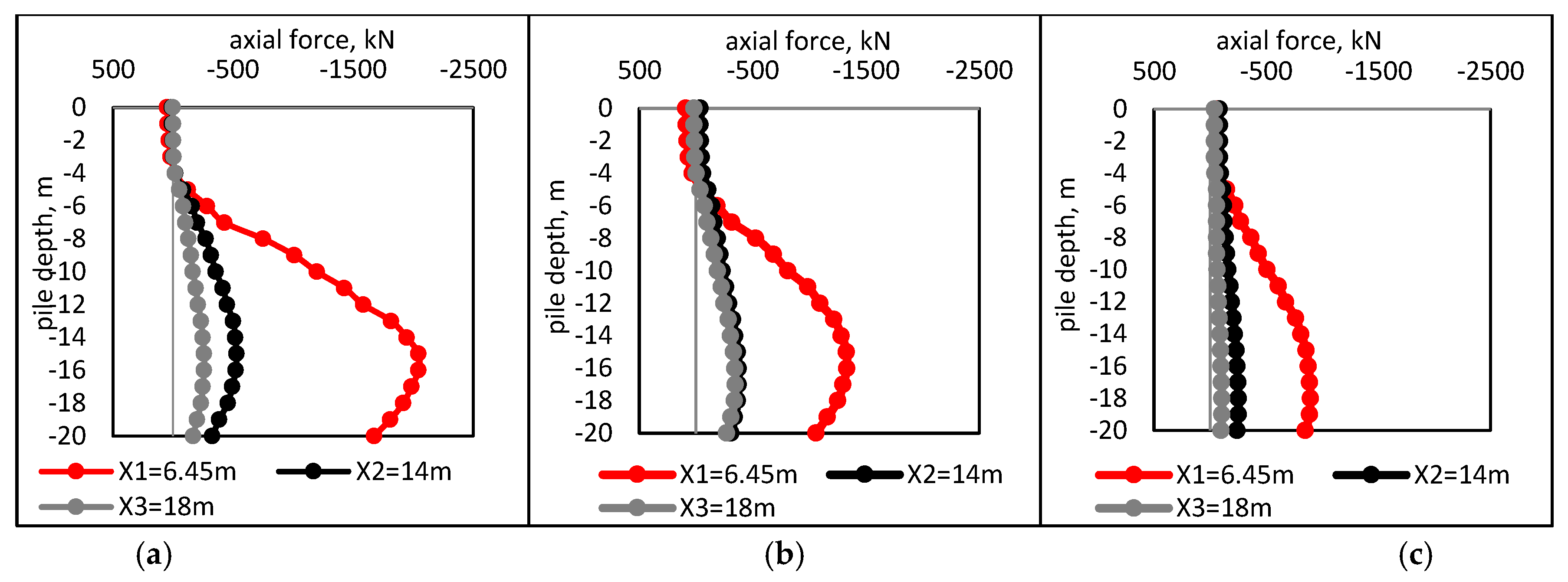
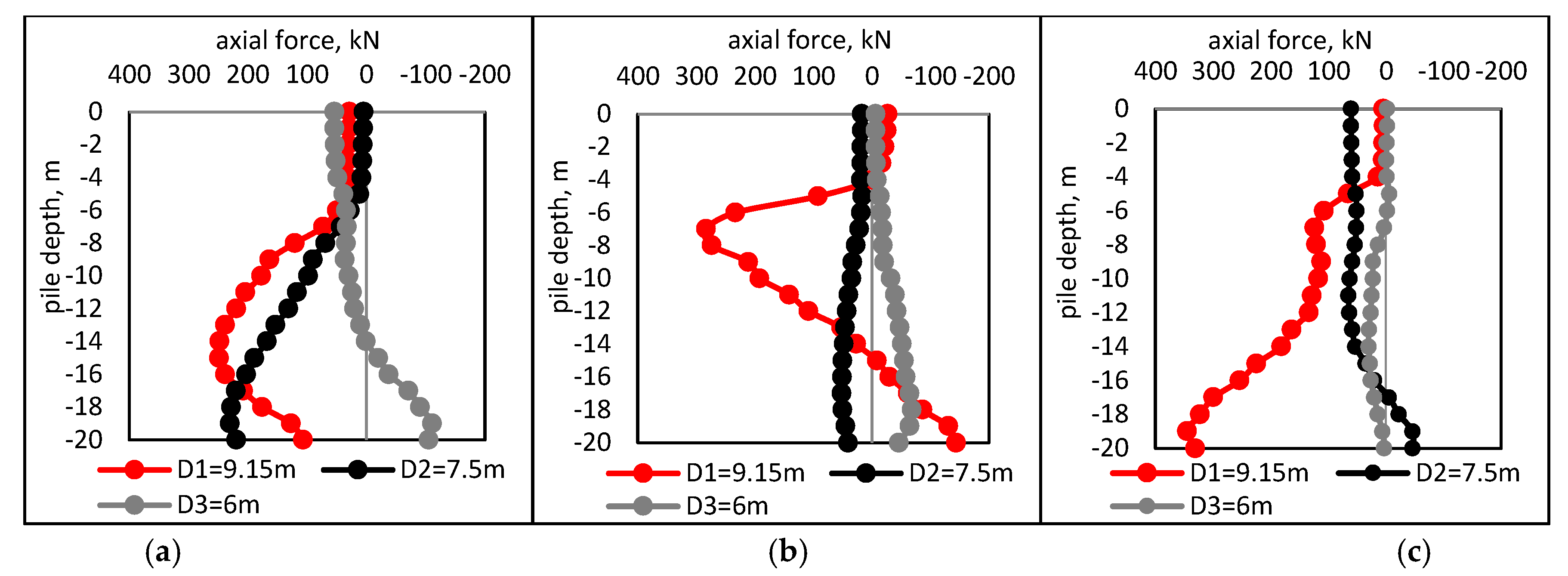
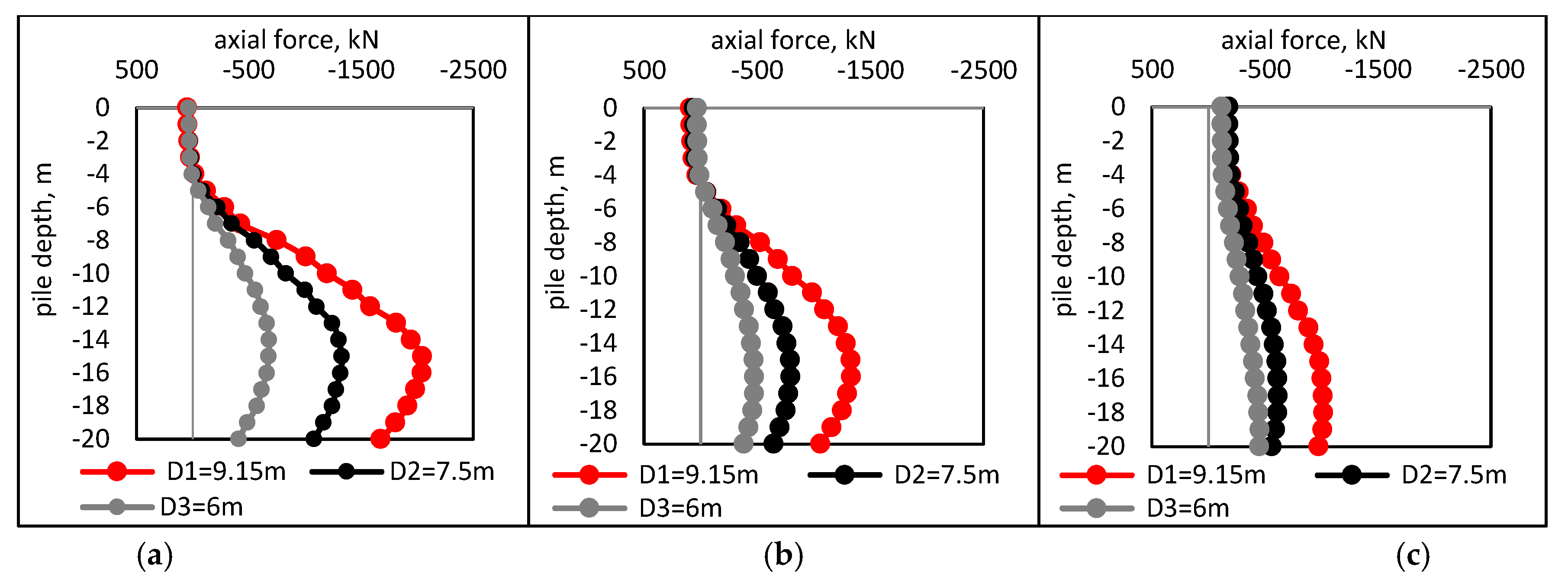
5.3.3. Axial Force of the Piles
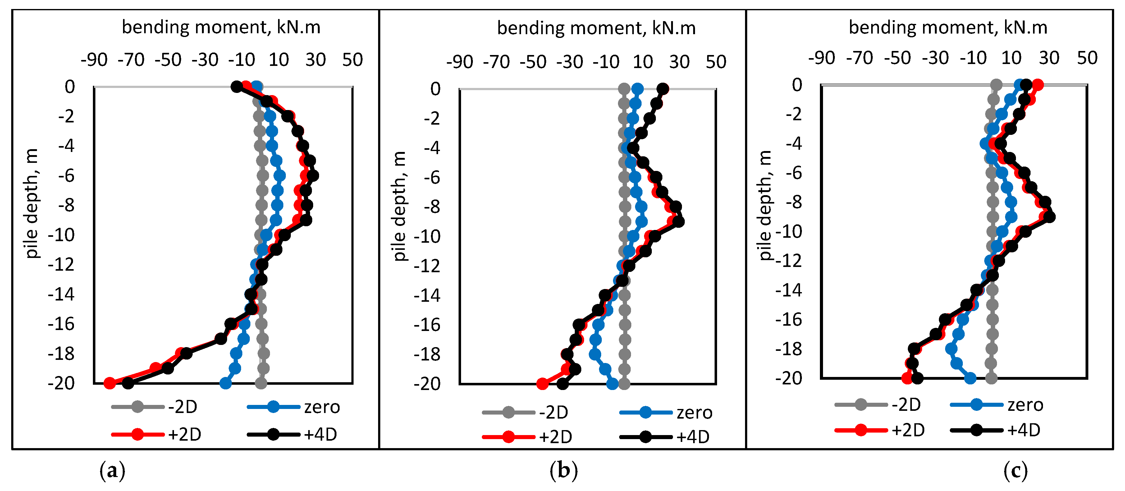
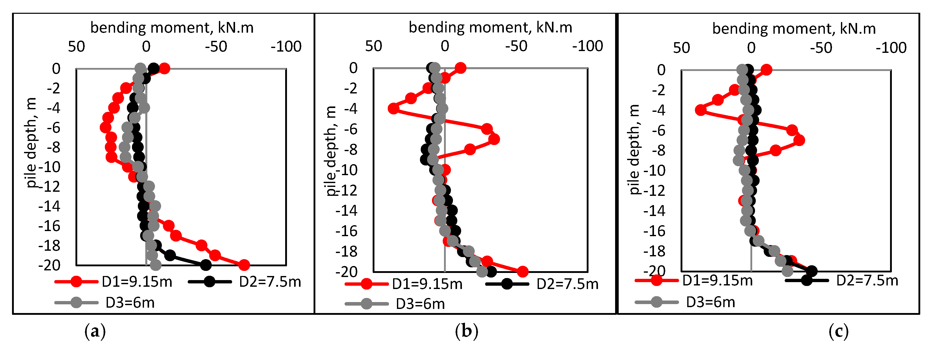
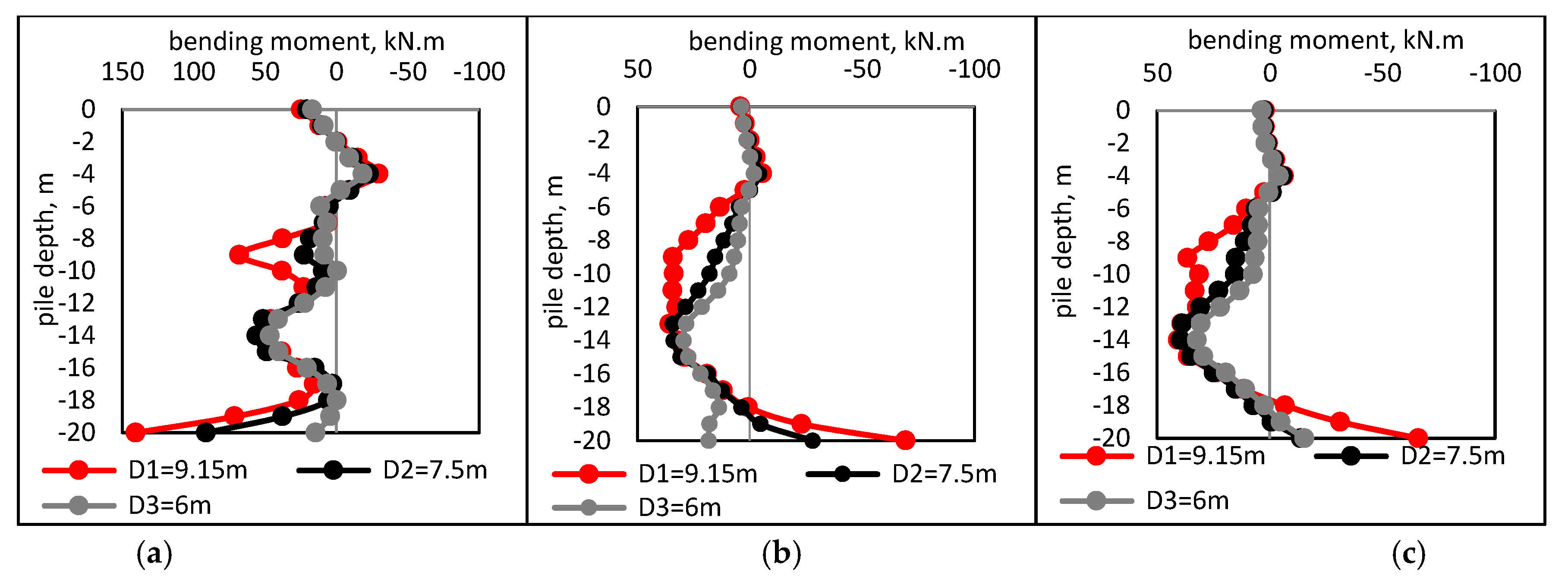
5.3.4. Bending Moment of the Piles
6. Conclusions
- The tunnel depth has an adverse influence on the response of piles. As the depth of the tunnel increases, the response of the piles decreases. However, to avoid serious damage to the adjacent pile foundation and structures, the tunnel depth and distance between the piles and the tunnel must be taken into consideration, being important to control effectively the piles responses.
- For both cases, deep and shallow tunnel, increasing the tunnel diameter causes the pile to increase the axial settlement and lateral deflection more as well as induce more additional axial force and bending moment.
- Decreasing the distance between the tunnel and the pile does cause a significant effect on pile response. However, the behavior of the variation is the same for Near, Middle, and Rear piles.
- For the deep tunnel (tunnel axis is located below the tip) and shallow tunnel (tunnel axis is located above the tip), the maximum bending moment and axial force occurred at the pile tip while the maximum axial settlement and lateral deflection occurred at the pile head.
- Larger variation to the pile axial force and bending moment were observed in the case of the shallow tunnel. However, the depth of the tunnel axis has much significant effect on pile response. Hence, the shallow tunnel does cause a greater response on piles more than the deep tunnel.
Author Contributions
Funding
Institutional Review Board Statement
Informed Consent Statement
Data Availability Statement
Conflicts of Interest
References
- Attewell, P.B.; Farmer, I.W. Ground disturbance caused by shield tunnelling in a stiff, overconsolidated clay. Eng. Geol. 1974, 8, 361–381. [Google Scholar] [CrossRef]
- Basile, F. Effects of tunnelling on pile foundations. Soils Found. 2014, 54, 280–295. [Google Scholar] [CrossRef]
- Al-Omari, R.R.; Al-Soud, M.S.; Al-Zuhairi, O.I. Effect of Tunnel Progress on the Settlement of Existing Piled Foundation. Stud. Geotech. Mech. 2019, 41, 102–113. [Google Scholar] [CrossRef]
- Wang, H.; Leung, C.F.; Yu, J.; Huang, M. Axial response of short pile due to tunnelling-induced soil movement in soft clay. Int. J. Phys. Model. Geotech. 2019, 20, 71–82. [Google Scholar] [CrossRef]
- Li, Y.; Zhang, W. Investigation on passive pile responses subject to adjacent tunnelling in anisotropic clay. Comput. Geotech. 2020, 127, 103782. [Google Scholar] [CrossRef]
- Simic-Silva, P.T.; Martínez-Bacas, B.; Galindo-Aires, R.; Simic, D. 3D simulation for tunnelling effects on existing piles. Comput. Geotech. 2020, 124, 103625. [Google Scholar] [CrossRef]
- Jacobsz, S.W.; Standing, J.R.; Mair, R.J.; Hagiwara, T.; Sugiyama, T. Centrifuge modelling of tunnelling near driven piles. Soils Found. 2004, 44, 49–56. [Google Scholar] [CrossRef]
- Franza, A.; Marshall, A.M. Centrifuge modeling study of the response of piled structures to tunneling. J. Geotech. Geoenviron. Eng. 2018, 144, 4017109. [Google Scholar] [CrossRef]
- Lee, C.J. Numerical analysis of the interface shear transfer mechanism of a single pile to tunnelling in weathered residual soil. Comput. Geotech. 2012, 42, 193–203. [Google Scholar] [CrossRef]
- Franza, A.; Marshall, A.M. Centrifuge and real-time hybrid testing of tunneling beneath piles and piled buildings. J. Geotech. Geoenviron. Eng. 2019, 145, 4018110. [Google Scholar] [CrossRef]
- Soomro, M.A.; Hong, Y.; Ng, C.W.W.; Lu, H.; Peng, S. Load transfer mechanism in pile group due to single tunnel advancement in stiff clay. Tunn. Undergr. Space Technol. 2015, 45, 63–72. [Google Scholar] [CrossRef]
- Soomro, M.A.; Ng, C.W.W.; Liu, K.; Memon, N.A. Pile responses to side-by-side twin tunnelling in stiff clay: Effects of different tunnel depths relative to pile. Comput. Geotech. 2017, 84, 101–116. [Google Scholar] [CrossRef]
- Loganathan, N.; Poulos, H.G.; Xu, K.J. Ground and pile-group responses due to tunnelling. Soils Found. 2001, 41, 57–67. [Google Scholar] [CrossRef]
- Soomro, M.A.; Bangwar, D.K.; Soomro, M.A.; Keerio, M.A. 3D Numerical Analysis of the Effects of an Advancing Tunnel on an Existing Loaded Pile Group. Eng. Technol. Appl. Sci. Res. 2018, 8, 2520–2525. [Google Scholar] [CrossRef]
- Huang, M.; Zhang, C.; Li, Z. A simplified analysis method for the influence of tunneling on grouped piles. Tunn. Undergr. Space Technol. 2009, 24, 410–422. [Google Scholar] [CrossRef]
- Mroueh, H.; Shahrour, I. A full 3-D finite element analysis of tunneling-adjacent structures interaction. Comput. Geotech. 2003, 30, 245–253. [Google Scholar] [CrossRef]
- Lee, G.T.K.; Ng, C.W.W. Effects of Advancing Open Face Tunneling on an Existing Loaded Pile. J. Geotech. Geoenviron. Eng. 2005, 131, 193–201. [Google Scholar] [CrossRef]
- Jongpradist, P.; Kaewsri, T.; Sawatparnich, A.; Suwansawat, S.; Youwai, S.; Kongkitkul, W.; Sunitsakul, J. Development of tunneling influence zones for adjacent pile foundations by numerical analyses. Tunn. Undergr. Space Technol. 2013, 34, 96–109. [Google Scholar] [CrossRef]
- Lueprasert, P.; Jongpradist, P.; Jongpradist, P.; Suwansawat, S. Numerical investigation of tunnel deformation due to adjacent loaded pile and pile-soil-tunnel interaction. Tunn. Undergr. Space Technol. 2017, 70, 166–181. [Google Scholar] [CrossRef]
- Loganathan, N. An Innovative Method for Assessing Tunnelling-Induced Risks to Adjacent Structures; Parsons Brinckerhoff: New York, NY, USA, 2011. [Google Scholar]
- Burland, J.B.; Wroth, C.P. Settlement of Buildings and Associated Damage. In Settlement of Structures; Pentech Pr.: London, UK, 1974; pp. 611–654. [Google Scholar]
- Boscardin, M.D.; Cording, E.J. Building response to excavation-induced settlement. J. Geotech. Eng. 1989, 115, 1–21. [Google Scholar] [CrossRef]
- Burland, J.B. Assessment of Risk of Damage to Buildings due to Tunnelling and Excavation; Imperial College of Science, Technology and Medicine: London, UK, 1995. [Google Scholar]
- Mair, R.J.; Taylor, R.N.; Burland, J.B. Prediction of Ground Movements and Assessment of Risk of Building Damage due to Bored Tunnelling. In Proceedings of the Geotechnical aspects of Underground Construction in Soft Ground, London, UK, 15–17 April 1996; pp. 713–718. [Google Scholar]
- Bolton, M.D.; Lu, Y.C.; Sharma, J.S. Centrifuge models of tunnel construction and compensation grouting. Geotech. Asp. Undergr. Constr. Soft Ground 1996, 15–17, 471–477. [Google Scholar]
- Loganathan, N.; Poulos, H.G.; Stewart, D.P. Centrifuge model testing of tunnelling-induced ground and pile deformations. Geotechnique 2000, 50, 283–294. [Google Scholar] [CrossRef]
- Franza, A.; Marshall, A.M.; Haji, T.; Abdelatif, A.O.; Carbonari, S.; Morici, M. A simplified elastic analysis of tunnel-piled structure interaction. Tunn. Undergr. Space Technol. 2017, 61, 104–121. [Google Scholar] [CrossRef]
- Abdullah, M.H.; Taha, M.R. A review of the effects of tunneling on adjacent piles. Electron. J. Geotech. Eng. 2013, 18, 2739–2762. [Google Scholar]
- Vakili, K.N.; Lavasan, A.A.; Schanz, T.; Datcheva, M. The Influence of the Soil Constitutive Model on the Numerical Assessment of Mechanized Tunneling. In Proceedings of the 8th European Conference on Numerical Methods in Geotechnical Engineering, Delft, The Netherlands, 18–20 June 2014; pp. 889–894. [Google Scholar]
- Zidan, A.F.; Ramadan, O.M.O. Three dimensional numerical analysis of the effects of tunnelling near piled structures. KSCE J. Civ. Eng. 2015, 19, 917–928. [Google Scholar] [CrossRef]
- Lee, C.J.; Jacobsz, S.W. The influence of tunnelling on adjacent piled foundations. Tunn. Undergr. Space Technol. 2006, 21, 430. [Google Scholar] [CrossRef]
- Lee, C.J. Three-dimensional numerical analyses of the response of a single pile and pile groups to tunnelling in weak weathered rock. Tunn. Undergr. Space Technol. 2012, 32, 132–142. [Google Scholar] [CrossRef]
- National Authority for Tunnel. “Tunnel from Attaba to Geish Shaft Monitoring Measurements”, Contract N 49/Metro, Phase 1"; National Authority for Tunnel: Cairo, Eqypt, 2010; pp. 270–271.
- Mocarthy Brothers Company. A Division of Design and Management, Consultant of Attaba Parking Garage; Mocarthy Brothers Company: Cairo, Egypt, 1984. [Google Scholar]
- Hamza Associates. Geotechnical Investigation Report; Hamza Associates: Cairo, Egypt, 2002. [Google Scholar]
- Ayasrah, M.; Qiu, H.; Zhang, X.; Daddow, M. Prediction of Ground Settlement Induced by Slurry Shield Tunnelling in Granular Soils. Civ. Eng. J. 2020, 6, 2273–2289. [Google Scholar] [CrossRef]
- Hejazi, Y.; Dias, D.; Kastner, R. Impact of constitutive models on the numerical analysis of underground constructions. Acta Geotech. 2008, 3, 251–258. [Google Scholar] [CrossRef]
- Fu, Y.; He, S.; Zhang, S.; Yang, Y. Parameter Analysis on Hardening Soil Model of Soft Soil for Foundation Pits Based on Shear Rates in Shenzhen Bay, China. Adv. Mater. Sci. Eng. 2020, 2020, 7810918. [Google Scholar] [CrossRef]
- Surarak, C.; Likitlersuang, S.; Wanatowski, D.; Balasubramaniam, A.; Oh, E.; Guan, H. Stiffness and strength parameters for hardening soil model of soft and stiff Bangkok clays. Soils Found. 2012, 52, 682–697. [Google Scholar] [CrossRef]
- Potts, D.M.; Zdravkovic, L.; Zdravković, L. Finite Element Analysis in Geotechnical Engineering: Application; Thomas Telford: London, UK, 2001. [Google Scholar]
- Potts, D.M.; Addenbrooke, T.I. A structure’s influence on tunnelling-induced ground movements. Proc. Inst. Civ. Eng. Geotech. Eng. 1997, 125, 109–125. [Google Scholar] [CrossRef]
- Mašín, D.; Tamagnini, C.; Viggiani, G.; Costanzo, D. Directional response of a reconstituted fine-grained soil—Part II: Performance of different constitutive models. Int. J. Numer. Anal. Methods Geomech. 2006, 30, 1303–1336. [Google Scholar] [CrossRef]
- Obrzud, R.F. On the use of the Hardening Soil Small Strain model in geotechnical practice. Numer. Geotech. Struct. 2010, 16, 15–32. [Google Scholar]
- Yang, M.; Sun, Q.; Li, W.; Ma, K. Three-dimensional finite element analysis on effects of tunnel construction on nearby pile foundation. J. Cent. South Univ. Technol. 2011, 18, 909. [Google Scholar] [CrossRef]
- Çelik, S. Comparison of Mohr-Coulomb and Hardening Soil Models’ Numerical Estimation of Ground Surface Settlement Caused by Tunneling Tünel Kazısından Dolayı Zemin Yüzeyindeki Oturmaların Mohr- Coulomb ve Pekleşen Zemin Modelleriyle Nümerik Tahminlerinin Karşılaşt. Iğdır Univ. J. Inst. Sci. Technol. 2017, 7, 95–102. [Google Scholar] [CrossRef]
- Teo, P.L.; Wong, K.S. Application of the Hardening Soil model in deep excavation analysis. IES J. Part A Civ. Struct. Eng. 2012, 5, 152–165. [Google Scholar] [CrossRef]
- Duncan, J.M.; Buchignani, A. An Engineering Manual for Settlement Studies; University of California: Oakland, CA, USA, 1976. [Google Scholar]
- The Housing and Building Research Center (HBRC). ECP 202/3, Egyptian Code for Soil Mechanics—Design and Construction of Foundations. Part 3, Shallow Foundation; The Housing and Building Research Center (HBRC): Cairo, Egypt, 2005. [Google Scholar]
- Zhao, C.Y.; Lavasan, A.A.; Barciaga, T.; Zarev, V.; Datcheva, M.; Schanz, T. Model validation and calibration via back analysis for mechanized tunnel simulations—The Western Scheldt tunnel case. Comput. Geotech. 2015, 69, 601–614. [Google Scholar] [CrossRef]
- Mayne, P.W.; Kulhawy, F.H. K0-OCR relationships in soil. J. Geotech. Eng. 1982, 108, 851–872. [Google Scholar]
- Cheng, C.Y.; Dasari, G.R.; Leung, C.F.; Chow, Y.K.; Rosser, H.B. 3D numerical study of tunnel-soil-pile interaction. Tunn. Undergr. Space Technol. 2004, 19, 381–382. [Google Scholar]
- Chen, L.T.; Poulos, H.G.; Loganathan, N. Pile Responses Caused by Tunneling. J. Geotech. Geoenviron. Eng. 1999, 125, 207–215. [Google Scholar] [CrossRef]
- Mroueh, H.; Shahrour, I. Three-dimensional finite element analysis of the interaction between tunneling and pile foundations. Int. J. Numer. Anal. Methods Geomech. 2002, 26, 217–230. [Google Scholar] [CrossRef]
- Lee, C.J.; Chiang, K.H. Responses of single piles to tunneling-induced soil movements in sandy ground. Can. Geotech. J. 2007, 44, 1224–1241. [Google Scholar]


| Soil Layers | Made Ground | Silty Clay | Upper Sand | Gravel | Middle Sand | Cobbles and Boulders | Lower Sand | |
|---|---|---|---|---|---|---|---|---|
| Parameter | ||||||||
| Thick. (m) | 4.00 | 5.00 | 11.00 | 1.50 | 1.50 | 6.50 | Extended | |
| Unit weight (kN/m3) | 17 | 17.67 | 19.5 | 20 | 19.5 | 21 | 19.5 | |
| Friction angle (°) | 27 | φu = 0 | 36 | 36 | 35 | 36 | 34 | |
| Cohesion (kPa) | 0 | = 111 | 0 | 0 | 0 | 0 | 0 | |
| Lateral earth pressure coefficient (-) | 0.546 | 1 | 0.412 | 0.384 | 0.384 | 0.412 | 0.384 | |
| Poisson’s ratio (-) | 0.3 | νu = 0.3 | 0.3 | 0.3 | 0.3 | 0.3 | 0.3 | |
| Dilatancy angle (°) | 0 | 0 | 6 | 6 | 5 | 6 | 4 | |
| Triaxial loading stiffness (MPa) | 4 | 27.75 | 15.33 | 100 | 16.48 | 19.61 | 19.61 | |
| Oedometer loading stiffness (MPa) | 4 | 27.75 | 15.33 | 100 | 16.48 | 19.61 | 19.61 | |
| Triaxial unloading stiffness (MPa) | 12 | 83.25 | 45.98 | 300 | 49.43 | 58.84 | 58.84 | |
| Parameters | Pile | Pile Cap | Lining | Shield | Grouting |
|---|---|---|---|---|---|
| Elasticity modulus (MPa) | 3.45 × 10⁴ | 1.4 × 10⁴ | 1.4 × 10⁴ | 2 × 10⁴ | 2 × 10⁴ |
| Unit weight (kN/m3) | 25 | 25 | 25 | 78 | 22.5 |
| Possion’s ratio (-) | 0.15 | 0.15 | 0.15 | 0.3 | 0.3 |
| Set Name Prefix | S1 | S2 | S3 | S4 | S5 | S6 | S7 | S8 | S9 | S10 |
|---|---|---|---|---|---|---|---|---|---|---|
| Shield | A:1 | A:2 | A:3 | A:4 | A:5 R:1 | A:6 R:2 | A:7 R:3 | A:8 R:4 | A:9 R:5 | A:10 R:6 |
| Segment | A:1 | A:2 | A:3 | A:4 | A:5 | A:6 | A:7 | |||
| Drilling pressure | A:1 | A:2 | A:3 | A:4 | A:5 | A:6 | A:7 | A:8 | A:9 | A:10 |
| Jack thrust | A:1 | A:2 R:1 | A:3 R:2 | A:4 R:3 | A:5 R:4 | A:6 R:5 | A:7 R:6 | |||
| Shield external pressure | A:1 | A:2 | A:3 | A:4 | A:5 | A:6 | A:7 | A:8 | A:9 | A:10 |
| Segment external pressure | A:1 | A:2 | A:3 | A:4 | A:5 | A:6 | ||||
| Hard grout | A:1 | A:2 | A:3 |
Publisher’s Note: MDPI stays neutral with regard to jurisdictional claims in published maps and institutional affiliations. |
© 2021 by the authors. Licensee MDPI, Basel, Switzerland. This article is an open access article distributed under the terms and conditions of the Creative Commons Attribution (CC BY) license (http://creativecommons.org/licenses/by/4.0/).
Share and Cite
Ayasrah, M.; Qiu, H.; Zhang, X. Influence of Cairo Metro Tunnel Excavation on Pile Deep Foundation of the Adjacent Underground Structures: Numerical Study. Symmetry 2021, 13, 426. https://doi.org/10.3390/sym13030426
Ayasrah M, Qiu H, Zhang X. Influence of Cairo Metro Tunnel Excavation on Pile Deep Foundation of the Adjacent Underground Structures: Numerical Study. Symmetry. 2021; 13(3):426. https://doi.org/10.3390/sym13030426
Chicago/Turabian StyleAyasrah, Mo’men, Hongsheng Qiu, and Xiedong Zhang. 2021. "Influence of Cairo Metro Tunnel Excavation on Pile Deep Foundation of the Adjacent Underground Structures: Numerical Study" Symmetry 13, no. 3: 426. https://doi.org/10.3390/sym13030426
APA StyleAyasrah, M., Qiu, H., & Zhang, X. (2021). Influence of Cairo Metro Tunnel Excavation on Pile Deep Foundation of the Adjacent Underground Structures: Numerical Study. Symmetry, 13(3), 426. https://doi.org/10.3390/sym13030426