Article

End Effect Analysis of a Slot-Less Long-Stator Permanent Magnet Linear Synchronous Motor

Department of Electrical, Engineering Harbin Institute of Technology, Harbin 150001, China
*
Author to whom correspondence should be addressed.
Symmetry 2021, 13(10), 1939; https://doi.org/10.3390/sym13101939
Submission received: 13 September 2021 / Revised: 8 October 2021 / Accepted: 12 October 2021 / Published: 15 October 2021
(This article belongs to the Section Computer)

Abstract

:
The implications of the end effect for flux linkage and thrust ripple in a slot-less long-stator permanent magnet linear synchronous motor (LSPMLSM), are analyzed in this paper. Since it is affected by the end effect, the air-gap magnetic field density under the end permanent magnet is different from that under the non-end permanent magnet, leading to asymmetry in the thrust ripple. For this reason, we establish a dynamic permanent magnet flux linkage model, which proves that the end effect leads to sub-harmonics in the permanent magnet flux linkage. The motor’s magnetic field distribution in the left and right parts is symmetrical. A thrust model taking into account the flux linkage sub-harmonics is established, from which the amplitude and period of the thrust ripple caused by the end effect can be calculated. There is no detent force for the slot-less LSPMLSM, and the end effect is the primary origin of the motor thrust ripple. In order to suppress the end effect, a method of increasing the end iron length is proposed, as a result of which the sub-harmonics in the flux linkage and the motor thrust ripple are effectively suppressed. Experimental and simulation results verify the results of this paper.

1. Introduction

In the permanent magnet linear synchronous motor (PMLSM), the force ripple ultimately limits the application of the motor in high-precision fields. Ironless PMLSMs are primarily used in the precision machining field, because of their low thrust ripple. Li and Tang [1] established a mathematical model for a coreless PMLSM and calculated the thrust coefficient and back-EMF coefficient. After comparing the motor’s function under the usual and Halbach distributions, they developed a prototype motor. Gyu [2] established a layered analytical structure for the ironless PMLSM mathematical model. The model was based on the equivalent magnetization current method for solving the motor thrust ripple. Zhi [3] established a thrust model based on the Maxwell stress tensor method. He pointed out that the thrust harmonic is an essential impact factor for ironless PMLSM thrust ripple, and the impact can be reduced by decreasing the harmonic component of the thrust.
The end effect is a significant drawback because it causes the thrust ripple of the motor. Hence, the end effect must be described precisely to lay the foundation for model building and improvement. One critical determinant for optimizing PMLSMs is the suppression of the end effect. Scholars have put forward many measures, including adjusting the primary component length, setting the auxiliary teeth, and optimizing the end core shape for a short-stator PMLSM [4,5,6,7].
For the long-stator permanent magnet linear synchronous motor (LSPMLSM), the secondary component of the LSPMLSM (permanent magnet) is set as the mover. The limited mover length in the PMSLM causes harmonics in the flux linkage and the harmonic magnetic field coupled with the current causes energy loss and thrust fluctuations. As mentioned above, this may affect the performance of the platform and make it vibrate [8,9,10,11,12]. It is not feasible to perform research on long-stator PMLSMs using a similar method as that used for explaining the end effect in short-stator PMLSMs [13,14,15]. In this paper, the end effect is suppressed by optimizing the size of the PM. Using this method, the mover can guarantee excellent stability under the operating conditions and can ensure high positioning accuracy. We focused on the slot-less LSPMLSM and researched the influence of the end effect on its operation. In this paper, we propose a suppression method to mitigate this problem. The study included numerical simulation and experimental verification, with the simulation results obtained from the end magnetic field model. We established the vector magnetic potential boundary and the master–slave boundary as the limiting factors. The density of the magnetic field fluctuates according to the end effect. We obtained multiple air-gap magnetic field density values for the end PMs and non-end PMs. In addition, a dynamic permanent magnet flux linkage was necessary. The end effect caused sub-harmonics in the linkage. Further thrust factors resulting from the permanent magnet flux linkage sub-harmonics were considered. These included the amplitude and period of the thrust ripple caused by the end effect. This resulted in a model that was sufficiently complete for simulation and analysis. In the experiments, we increased the end iron length. This suppressed the end effect and reduced the motor thrust ripple. A self-made prototype was developed as described above. We tested the thrust fluctuation and performed a statistical analysis. Comparison with the simulation results showed that this method was valid and effective. The vibration and the positional accuracy were controlled, within a certain range.

2. Magnetic Field Analysis Considering the End Effect

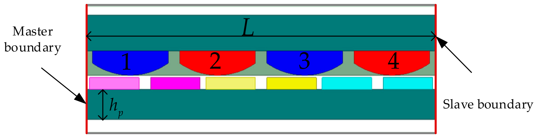
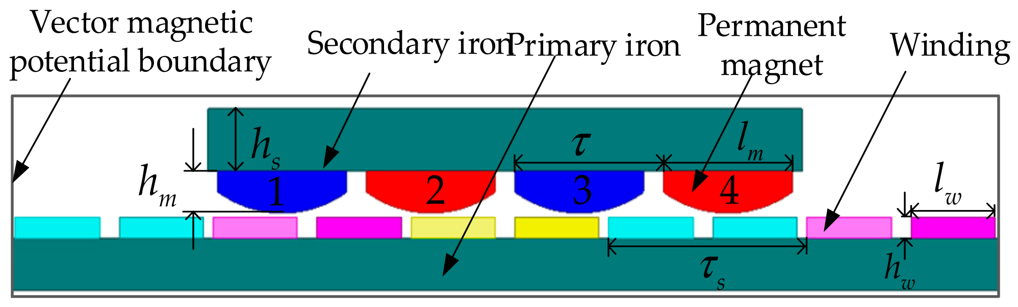
2.1. Structure of the Motor

Figure 1 shows the structure of the slot-less LSPMLSM with three slots and four poles. The primary component was used as the stator, in which the slot-less structure was adopted. The insulating frameworks were used to support the winding coils. After the epoxy powder filling process, the winding coils were attached to the surface of the primary iron core. The LSPMLSM secondary operated as a moving part, and the permanent magnets were surface mounted on the secondary iron core. The surface of the permanent magnet was designed to be arc-shaped to decrease the harmonics of the air-gap magnetic field density. The principal component parameters of the LSPMLSM are listed in Table 1.

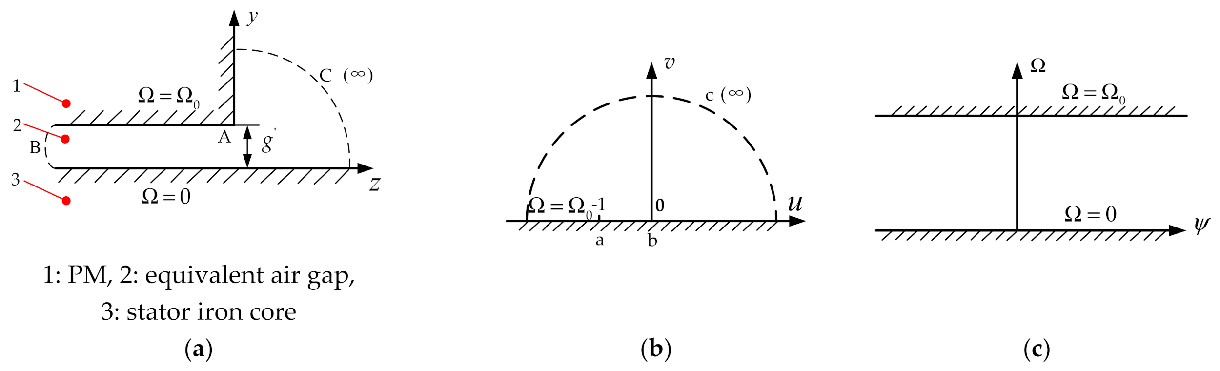
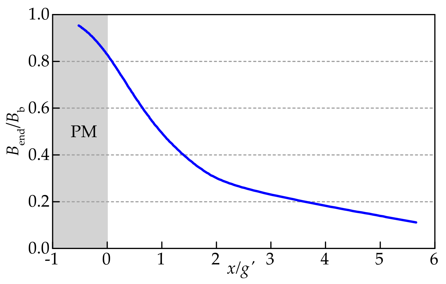
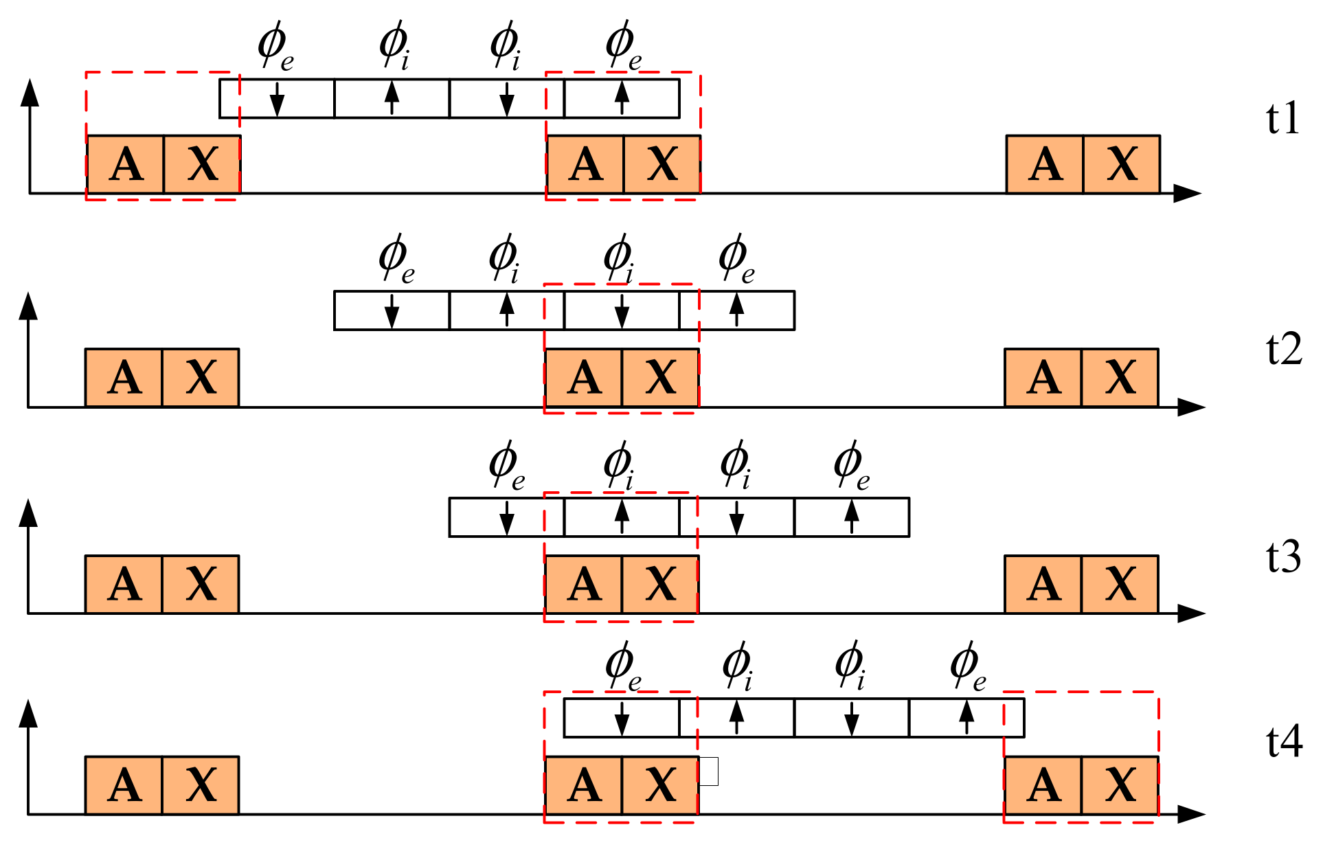
2.2. Model of End Magnetic Field

In the LSPMLSM, the armature stator is longer than the PM mover. For the PM mover, the longitudinal end effect distorts the magnetic field. Therefore, the end magnetic field model, taking into account the longitudinal end effect, was first established via the Schwarz–Christoffel transformation [16,17,18,19]. Figure 2 shows the coordinate plane in the Schwarz–Christoffel transformation.
In Figure 2, g is the length of the equivalent air gap and Ω 0 is the magnetic vector potential of the PM area. The relationship between planes z, w, and t is as follows.
z w : z = g π 2 ( w + 1 ) 1 2 + ln ( w + 1 ) 1 2 1 ( w + 1 ) 1 2 + 1 w t : w = e π t or t = 1 π ln w z t : z = g π 2 ( e π t + 1 ) + ln 2 ( e π t + 1 ) 1 2 ( e π t + 1 ) + 1
The scalar magnetic potential in the plane is denoted by φ ( x , y ) and that in plane t is denoted by ψ ( p , q ) , hence
φ ( x , y ) = ψ [ p ( x , y ) , q ( x , y ) ]
In plane z, the magnetic field intensity is equal to the negative gradient of the scalar magnetic potential
H z = H x + j H y = φ x φ y
and in the plane t,
H t = H p + j H q = ψ p ψ q
From (2), one obtains
φ x = ψ p p x + ψ q q x φ y = ψ p p y + ψ q q y
Combining (3), (4), and (5) yields
H z = H p p x + H q q x + j ( H p p y + H q q y )
After applying Cauchy–Riemann conditions, (6) becomes
H z = ( H p + j H q ) ( p x j q x ) = H t ( p x j q x )
since
z = x + j y t = p ( x , y ) + j q ( x , y )
Hence, the relationship between Hz and Ht is as follows.
H z = H t | t z |
After two transformations (from plane z to plane w and then from plane w to plane t), the end magnetic field distribution in plane t can be obtained
B end = μ 0 H z = μ 0 H t t z = B t ( w + 1 ) 1 2
where μ 0 is the vacuum permeability, H is the magnetic field intensity, and Bb is the magnetic field density at point b in plane z.
Figure 3 shows the variation curves of Bend/Bb with x when z = x and w = u. Its exponential fitting expression is
B end = B b e x g x 0 B b e x + [ ( 2 p 1 ) τ + l m ] g x [ ( 2 p 1 ) τ + l m ]
where g = k c ( g + h m / μ r ) , k c is the Carter’s coefficient, hm and lm are the height and length of the PM, μ r is the relative permeability of the PM, p is the pole pair, and τ is the pole pitch.
From Figure 3, it can be seen that the magnetic field density decreases in the end area of the permanent magnet due to the influence of the end effect.

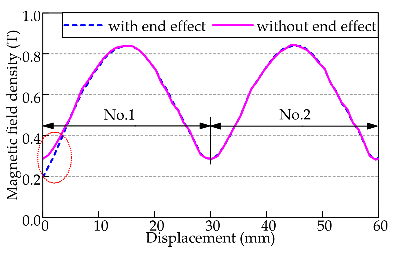
2.3. Simulation Verification

The vector magnetic potential boundary and the master–slave boundary models are built using finite element simulation software, as shown in Figure 1 and Figure 4, respectively. The vector magnetic potential boundary condition is the conventional scheme used in linear motor simulation, in which the magnetic line at the boundary is parallel to the given boundary line [20]. Using the master–slave boundary condition, the linear motor model can be considered equivalent to the rotary motor model with an infinite radius [21].
In the master–slave boundary model, the lengths of the primary and secondary components are all infinite. Thus, the motor has no end effect. Nevertheless, in the conventional vector magnetic potential boundary model, the motor has an end effect. By comparing the variation law of the air-gap magnetic field density in the two models, the influence of the end effect on the air-gap magnetic field density can be obtained. For convenience of analysis, the permanent magnets are numbered from left to right as No. 1, No. 2, No. 3, and No. 4, respectively. No. 1 and No. 4 represent the end PMs, while No. 2 and No. 3 represent the non-end PMs.
The air-gap magnetic field density can be obtained using the simulation models shown in Figure 1 and Figure 4. Figure 5 shows the air-gap magnetic field density at the upper surface of the winding coils. In the master–slave boundary model, there is no end effect, so that the waveform of the air-gap magnetic field density is completely sinusoidal. The air-gap magnetic field densities under the four PMs are identical. In the conventional vector magnetic potential boundary model, there is an end effect. The end effect results in the air-gap magnetic field density under the end PMs being smaller than under the non-end PMs, which is consistent with the rule shown in Figure 3. The magnetic density decreases in the end area of the permanent magnet due to the influence of the end effect.

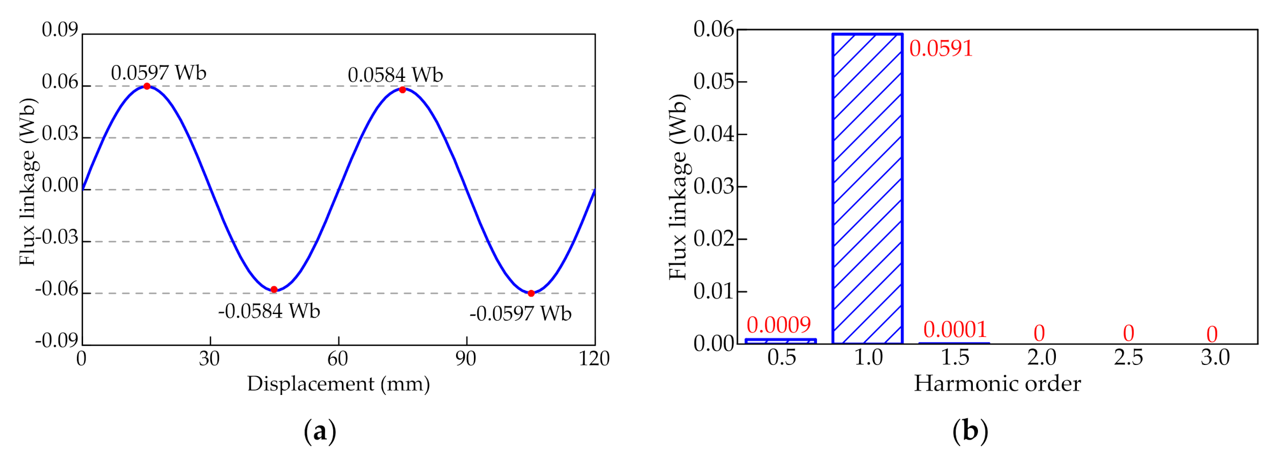
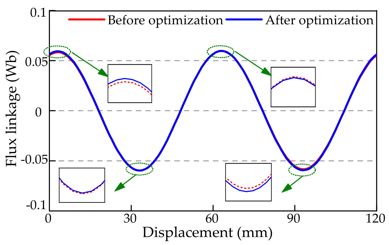
3. Influence of the End Effect on the Flux Linkage

Due to the influence of the end effect, the magnetic field density decreases in the end area of the permanent magnet. The change in air-gap magnetic field density has a specific influence on the permanent magnet flux linkage of the motor. Taking phase A as an example, a dynamic model was established to analyze the influence of the end effect on the permanent magnet flux linkage, as shown in Figure 6. Here, φ e is the flux produced by the end PMs (No. 1 and No. 4, as shown in Figure 1), while φ i is the flux produced by the non-end PMs (No. 2 and No. 3). It can be seen that at t1, t2, t3, and t4, the fluxes of phase A are 7 ϕ e / 6 + ϕ i / 6 , 7 ϕ i / 6 + ϕ e / 6 , 7 ϕ i / 6 + ϕ e / 6 , and 7 ϕ e / 6 + ϕ i / 6 , respectively. The fluxes at t1 and t4 are identical, and those at t2 and t3 are also identical. Due to the influence of the end effect, φ e φ i . In this case, the fluxes at t1 are not equal to those at t2. As a result, a sub-harmonic content, with a period of 4 times the pole pitch (3 times the slot pitch), is introduced into the permanent magnet flux linkage. In the same way, the permanent magnet flux linkages of phases B and C also contain sub-harmonics.
Figure 7 shows the permanent magnet flux linkage for phase A. In Figure 7a, the range of the x-axis is 120 mm, corresponding to 4 times the pole pitch. The peak values are 0.0597 Wb, 0.0584 Wb, 0.0584 Wb, and 0.0597 Wb, respectively. Due to the end effect, these four peak values are not the same. Figure 7b shows the harmonics distribution of the permanent magnet flux linkage, where the period is 2 times the pole pitch. It can be seen that the waveform contains sub-harmonics, mainly the 1/2 sub-harmonic. The amplitude of the 1/2 sub-harmonic is 0.0009 Wb, accounting for 1.5% of the amplitude of the fundamental wave.

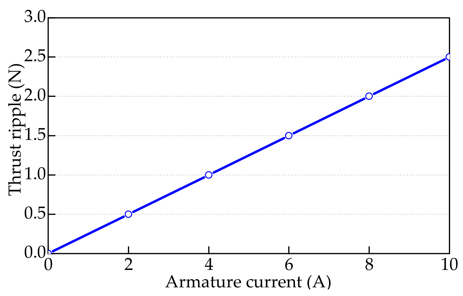
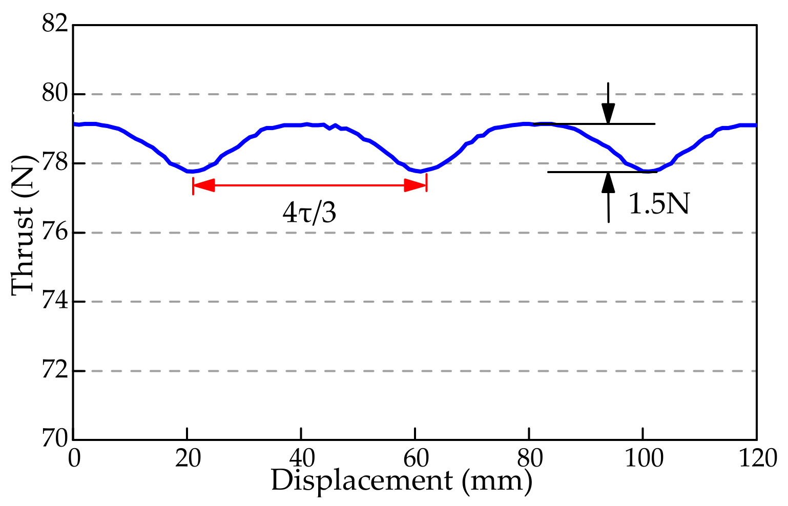
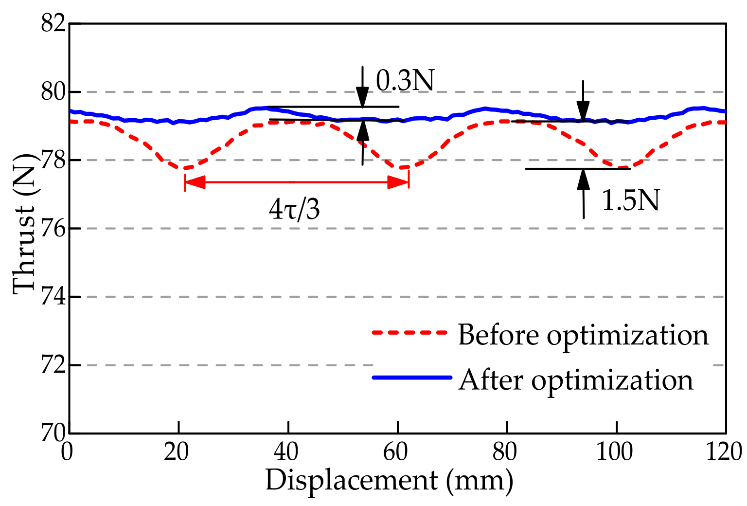
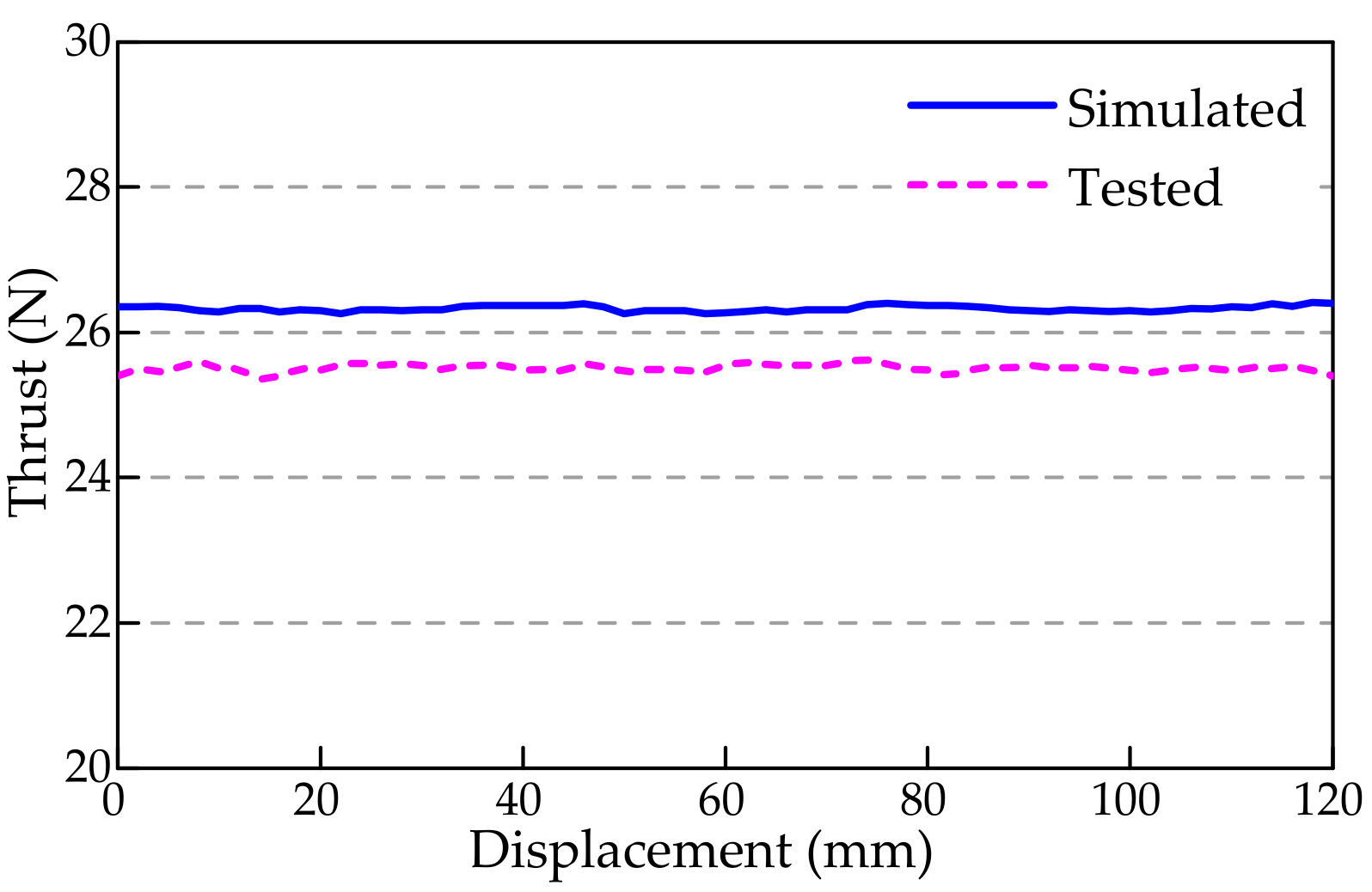
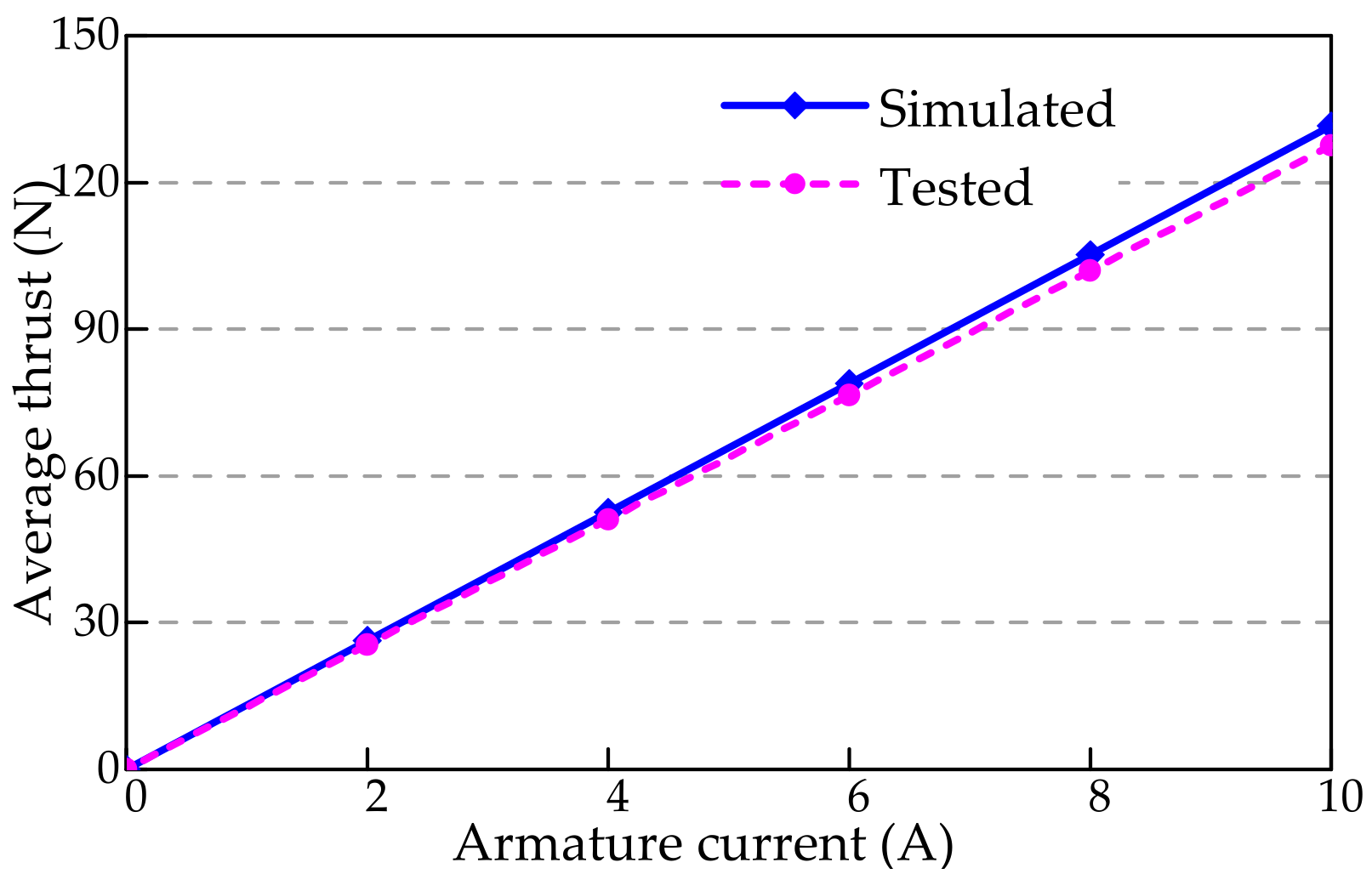
4. Influence of the End Effect on the Thrust Ripple

4.1. Thrust Model Considering the End Effect

In this section, the thrust model is established, in which the permanent magnet flux linkage sub-harmonics caused by the end effect are considered. The three-phase permanent magnet flux linkages can be represented by
ψ f a ( x ) = ψ 1 sin ( π τ x ) + ψ 0 sin ( π 2 τ x ) ψ f b ( x ) = ψ 1 sin ( π τ x 2 π 3 ) + ψ 0 sin ( π 2 τ x + 2 π 3 ) ψ f c ( x ) = ψ 1 sin ( π 2 τ x + 2 π 3 ) + ψ 0 sin ( π 2 τ x 2 π 3 )
where ψ 1 is the amplitude of the fundamental component, ψ 0 is the amplitude of the 1/2 sub-harmonic component, and x is the relative position between the primary and the secondary components.
In the direct-quadrature (d-q) axis coordinate system, the permanent magnet flux linkages of the motor can be represented as
ψ f d ( x ) = 3 2 ψ 1 3 2 ψ 0 cos ( 3 π 2 τ x ) ψ f q ( x ) = 3 2 ψ 0 sin ( 3 π 2 τ x ) ψ 0 sin ( π 2 τ x + π 3 )
When there is no end effect, ψ f d is a constant and ψ f q is equal to zero. However, here, due to the influence of the end effect, ψ f d contains a harmonic component and ψ f q is not equal to zero.
The formula for the calculation of the motor thrust is
f ( x ) = 3 π 2 τ [ ψ f d ( x ) i q ( x ) ψ f q ( x ) i d ( x ) ]
where i d and i q are the d-axis current and the q-axis current, respectively.
When the current vector control strategy is adopted for the motor, the d-axis current is zero, and the q-axis current is at the maximum value, i max . Putting (13) into (14), the motor thrust can be calculated by
f ( x ) = 9 π 4 τ ψ 1 i max 9 π 4 τ ψ 0 i max cos ( 3 π 2 τ x )
The motor thrust can be divided into two parts: the average thrust and the thrust ripple. The period of the thrust ripple is 4/3 of the pole pitch. The amplitude of the thrust ripple is proportional to the q-axis current and the amplitude of the 1/2 sub-harmonic in the permanent magnet flux linkage. Hence, the thrust ripple is caused by the sub-harmonic in the permanent magnet flux linkage. In the final analysis, it is caused by the end effect. When there is no end effect, the thrust ripple is the theoretically equal to zero.

4.2. Simulation Verification

The finite element simulation can give the thrust of the motor. Figure 8 shows the curves of the thrust ripple varying with the armature current. It can be seen that the thrust ripple is proportional to the armature current, which is consistent with (15). When the armature current is 6 A, the motor is in an underrated state. Figure 9 shows the waveform of the thrust. It can be seen that the period of the thrust ripple is 4/3 of the pole pitch, which is also consistent with (15). In this study, the thrust ripple rate is defined as the ratio of the thrust ripple to the average thrust. The thrust ripple was 1.5 N and the average thrust was 78.3 N. Hence, the thrust ripple rate was 1.9%.

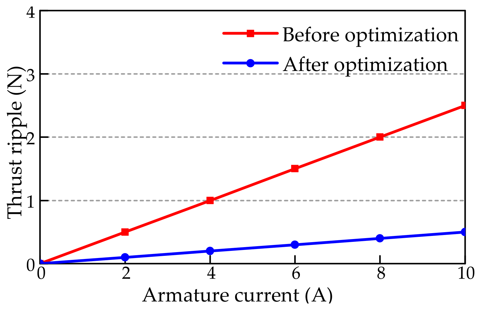
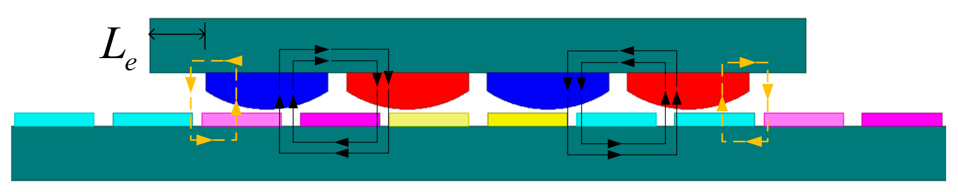
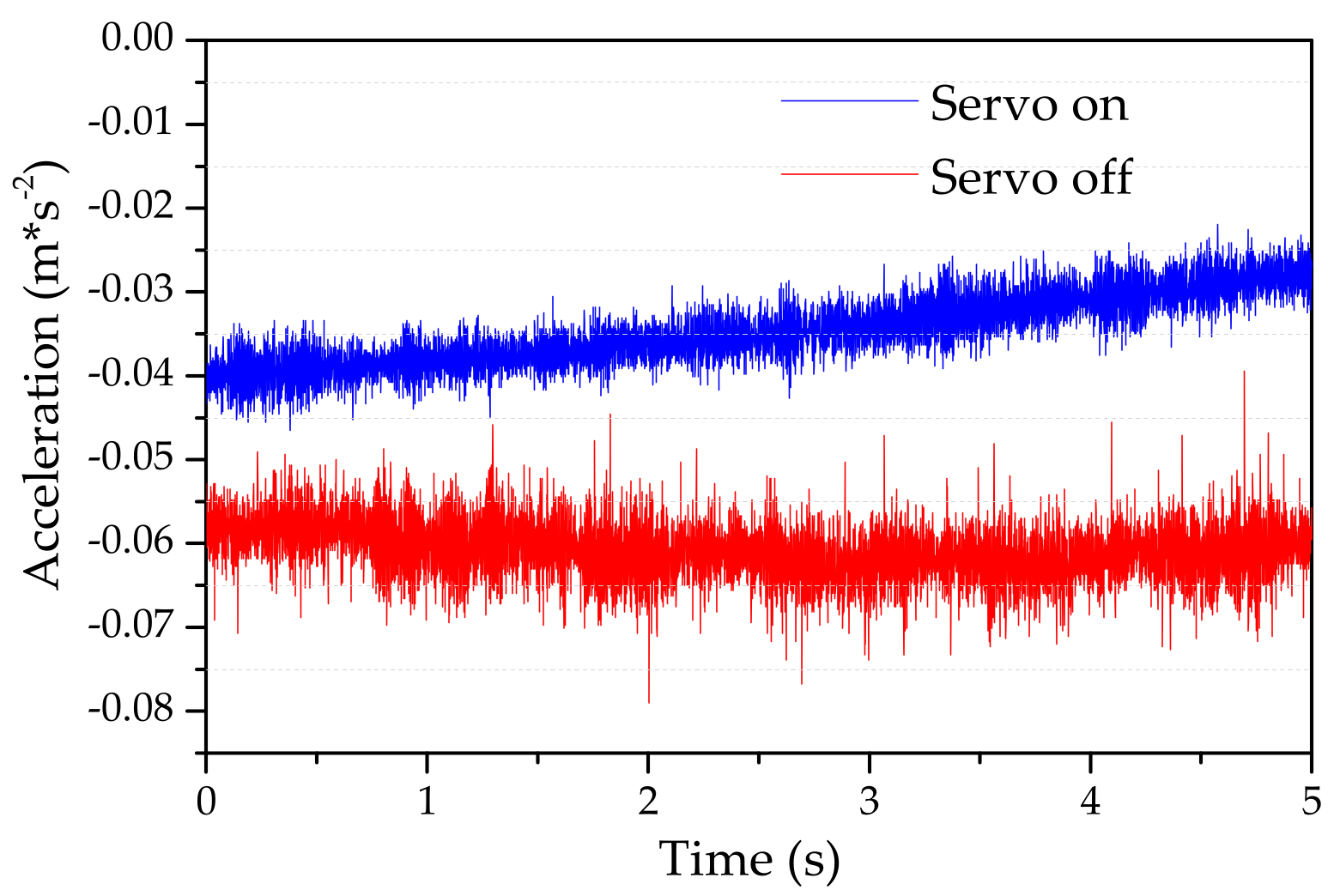
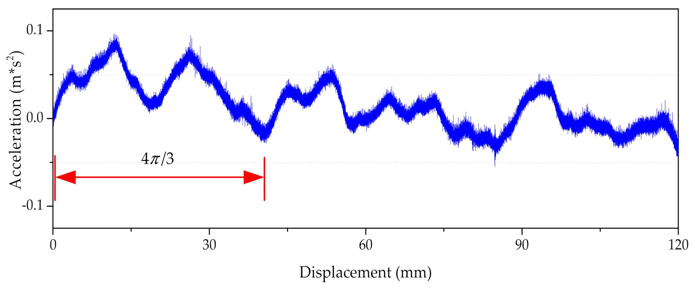
5. Suppression of the End Effect

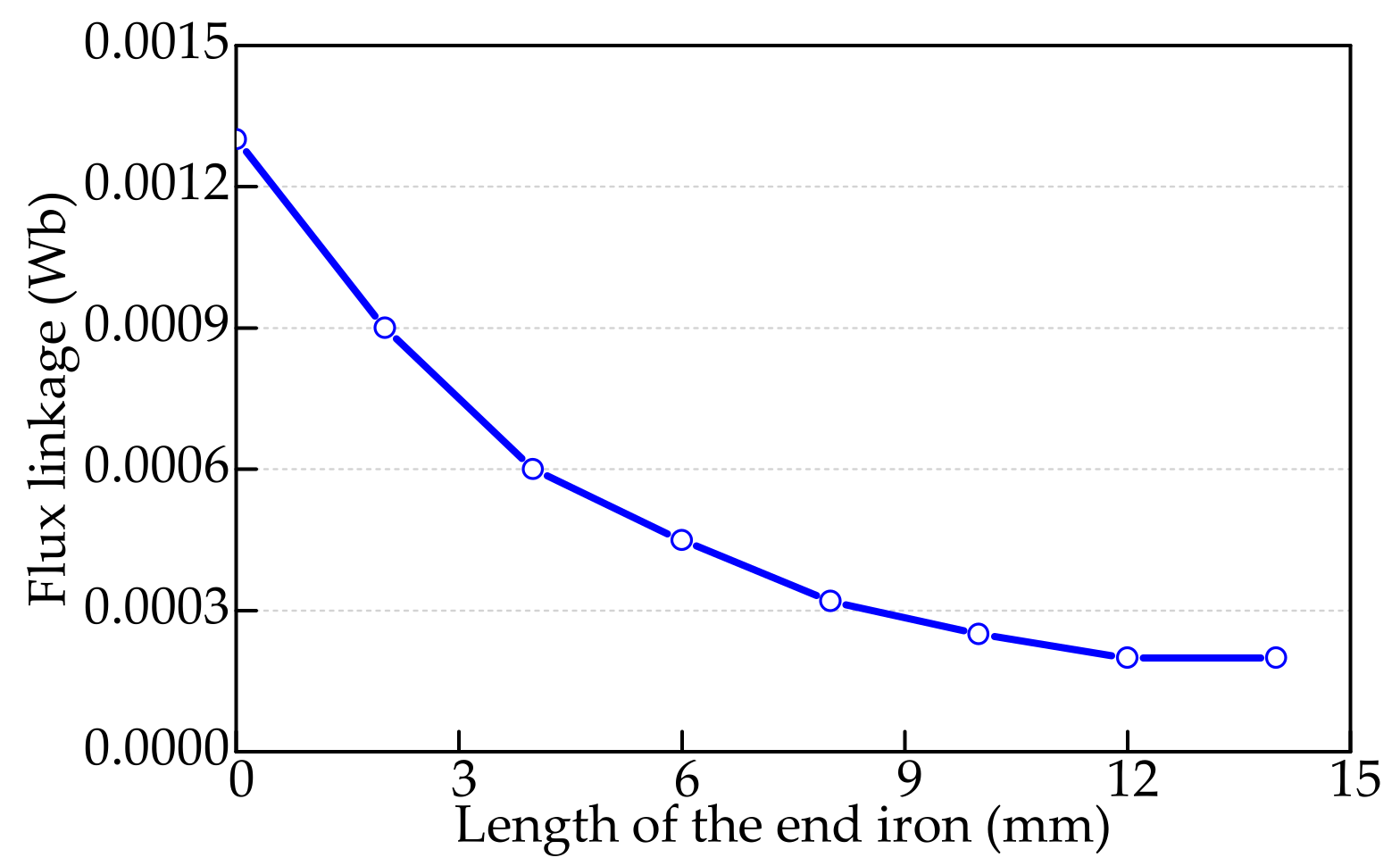
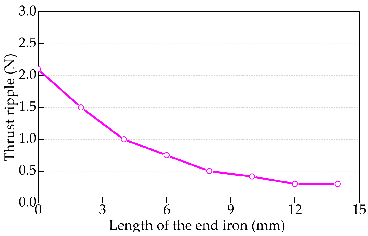
5.1. End Effect Suppression by Increasing the End Iron Length

In order to suppress the end effect and the thrust ripple of the motor, the method of increasing the end iron length in the secondary component is proposed in this section, as shown in Figure 10. According to the end effect mechanism, in order to weaken the end effect, it is necessary to compensate for the uneven distribution of the magnetic flux under each PM. Increasing the length of the end iron in the PM mover can achieve this effect simply and effectively. It can introduce a magnetic conductivity branch into the end magnetic circuit. Then, the difference between the flux under the end permanent magnet and that under the non-end permanent magnet is reduced. Therefore, the influence of the end effect can be suppressed effectively.
Figure 11 shows the curve of the 1/2 sub-harmonics in the permanent magnet flux linkage varying with the length of the end iron. With an increase in the end iron length, the 1/2 sub-harmonics were reduced. When the end iron length was greater than 12 mm, the 1/2 sub-harmonics did not change with the length of the end iron. Figure 12 shows the curve of the thrust ripple varying with the length of the end iron. The change rule of the curve in Figure 9 is the same as that in Figure 8, because the thrust ripple is proportional to the 1/2 sub-harmonic in the permanent magnet flux linkage.
According to the result in Figure 12, the optimal value for the end iron length was 12 mm. The waveforms of the permanent magnet flux linkages before and the after the optimization were compared, as shown in Figure 13. Before the optimization, the peak values were 0.0597 Wb, 0.0584 Wb, 0.0584 Wb, and 0.0597 Wb, respectively. After the optimization, the peak values were 0.0596 Wb, 0.0593 Wb, 0.0593 Wb, and 0.0596 Wb, respectively. The sub-harmonics in the permanent magnet flux linkage were reduced.
Figure 14 shows the curves of the thrust ripple varying with the armature current, before and after the optimization. Figure 15 shows the waveforms of the motor thrust before and after the optimization, with a 6 A armature current. After the optimization, the thrust ripple was 0.3 N and the average thrust was 79.2 N. Comparing this with the case before the optimization, the average thrust was increased by 1.1% and the thrust ripple rate was reduced from 1.9% to 0.4%.

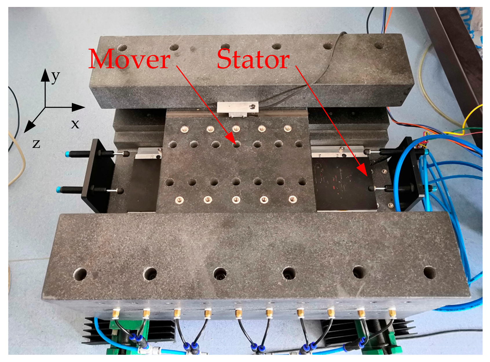
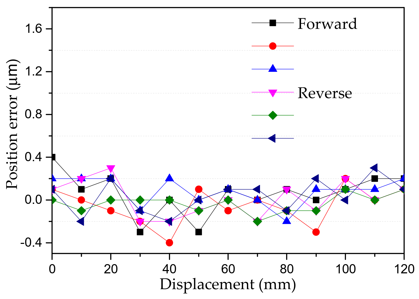
5.2. Experimental Verification

A prototype was developed and its thrust characteristics tested to verify the research presented in this paper. Figure 16 shows the prototype test platform. The platform included an air guideway, a marble base, a grating ruler, an acceleration sensor, a driver, a DC source, and an oscilloscope. The secondary core of the prototype was moved with the platform actuator, and the primary core was mounted on the base.
During the experiment, the driver controlled the motor to move at a constant speed. A high-precision grating ruler gave the mover position signal. The acceleration sensor was installed on the mover to record the thrust ripple of the prototype. In the test, the entire platform was tilted at an angle to ensure gravity could load the motors, so that the thrust characteristics of the prototype could be measured.
Figure 17 shows the tested and simulated thrust of the motor, with an armature current of 2 A. In the simulation, the average thrust was 26.3 N and the thrust ripple rate was 0.4%. In the test, the average thrust was 25.5 and the thrust ripple rate was 0.8%. The test thrust ripple rate was slightly higher than the simulated thrust ripple rate, mainly due to assembly error and the current harmonic caused by the drive control. In general, the thrust ripple rate was clearly suppressed, meeting the design requirements. This verifies the research presented in this paper.
The mover outputs static thrust when a DC current powers the windings. The thrust varies with the mover position while dragging [22,23]. When the thrust is highest, the current is close to the q-axis current, whereas the point of lowest thrust corresponds to the d-axis position. The mover of the platform was connected to one side of the baffle through a tension pressure sensor, and then the static thrust test was performed for the prototype. Figure 18 shows the static thrust varying with the armature current. The measurement results are identical to the numerical simulations, with maximum deviations of 3%.
In order to ensure the SLPMLSM had acceptable performance, a series of tests were performed, such as the vibration and positioning accuracy tests on the x-axis (the direction of motion of the mover) shown in Figure 16.
The accelerometer was fixed onto the mover to collect the vibration signals. In order to verify the stability of the fixed-point control, the vibration performance of the mover was investigated, as shown in Figure 19. When the mover was fixed at one point on the air bearing, not controlling the motor (servo off), the value of the acceleration vector was between 0.045 m·s2 and 0.08 m·s2. However, when the mover was in the same position under the servo control (servo on), the value of the acceleration vector was between 0.025 m·s2 and 0.045 m·s2.
Next, the vibration value for the mover was obtained. Figure 20 shows the relationship between the acceleration of the vibration and the displacement when the mover speed is 0.03 mm/s. The vibration waveform is periodic, with a period of 4/3 of the pole pitch, indirectly proving the existence of the thrust ripple.
Positioning tests for the prototype were carried out to check the positioning accuracy of the motor. The displacement range of the mover was 0~120 mm, a measuring point was taken every 10 mm, and the running speed was 0.03 mm/s. Continuous forward and reverse measurements were repeated three times, and the results are shown in Figure 21.
By observing the various measurements, the trend of the changes in the positioning error is apparent. The values are consistent with the thrust ripple, although the results vary from point to point. This phenomenon is the result of the combined action of the motor and the air bearing. The positioning accuracy of the prototype was 0.335 μ m .

6. Conclusions

The magnetic field analysis model fully described the dynamic magnet type of permanent magnet linear synchronous motor. The first step in establishing the model was calculating and simulating the distribution of the end magnetic field. The end force could be obtained directly from the analytical solution. Furthermore, we could obtain the magnetic field harmonics caused by the dynamic magnetic linear motor end force. Optimizing the motor size was proposed to decrease the thrust fluctuation and vibration in a given motor. Since both sides of the end force on the motor are centrosymmetric, vector synthesis was included to suppress motor thrust fluctuations. By building an experimental prototype, we obtained the thrust waveform of the motor using acceleration sensors. Many experiments, including optimization, comparisons, and simulations were undertaken to develop the final effective method. The final results showed that this method can lower the rate of thrust fluctuation below 21.1%. We paid considerable attention to the end back effect of the motor. However, there are still other factors that need to be considered. As well as the motor, it is also important to take the air bearing into consideration. Considering both together would result in a high-precision machining process, a low vibration amplitude, and a more stable system.

Author Contributions

Conceptualization, L.L. and Y.Z.; methodology, Y.Z.; software, Q.T.; validation, W.Z., T.S. and Z.H.; formal analysis, Q.T.; investigation, Y.Z.; resources, L.L. and W.Z.; data curation, Q.T. and Y.Z.; writing—original draft preparation, Y.Z.; writing—review and editing, Q.T.; visualization, Y.Z. And Q.T.; supervision, L.L.; project administration, W.Z.; funding acquisition, L.L. and W.Z. All authors have read and agreed to the published version of the manuscript.

Funding

This research was funded by Natural Science Foundation of China, grant number 52077041, grant number 51690182, and the Science Challenge Project (No. TZ2018006).

Institutional Review Board Statement

Not applicable.

Informed Consent Statement

Not applicable.

Data Availability Statement

Not applicable.

Conflicts of Interest

The authors declare no conflict of interest.

References

  1. Li, L.Y.; Tang, Y.B.; Liu, J.X. Multiobjective Design Optimization of Ironless Permanent Magnet Linear Synchronous Motors for Improved Thrust and Reduced Thrust Ripple. Appl. Mech. Mater. 2013, 416–417, 395–400. [Google Scholar]
  2. Kang, G.H.; Hong, J.P.; Kim, G.T. A novel design of an air-core type permanent magnet linear brushless motor by space harmonics field analysis. IEEE Trans. Magn. 2001, 37, 3732–3736. [Google Scholar] [CrossRef]
  3. Zhi, F.; Zhang, M.; Zhu, Y.; Li, X. Analysis and Elimination of Harmonics in Force of Ironless Permanent Magnet Linear Synchronous Motor. Proc. Chin. Soc. Electr. Eng. 2017, 37, 2101–2109. [Google Scholar]
  4. Lee, S.; Kim, S.; Saha, S.; Zhu, Y.; Cho, Y. Optimal structure design for minimizing detent force of PMLSM for a rope-less elevator. IEEE Trans. Magn. 2014, 16, 64. [Google Scholar]
  5. Ma, M.; Li, L.; He, Z.; Chan, C. Influence of longitudinal end effects on electromagnetic performance of a permanent magnet slot less linear launcher. IEEE Trans. Plasma Sci. 2013, 41, 1161–1166. [Google Scholar] [CrossRef]
  6. Zhu, Y.W.; Lee, S.G.; Chung, K.S.; Cho, Y.H. Investigation of Auxiliary Poles Design Criteria on Reduction of End Effect of Detent Force for PMLSM. IEEE Trans. Magn. 2009, 45, 2863–2866. [Google Scholar] [CrossRef]
  7. Li, J.; Huang, X.; Zhou, B.; Yu, H.; Huang, Q. Design principle of a 16-pole 18-slot two-sectional modular permanent magnet linear synchronous motor with optimisation of its end tooth. IET Electr. Power Appl. 2020, 14, 441–447. [Google Scholar] [CrossRef]
  8. Li, A.L.; Ma, B.M.; Chen, C.Q. Detent force analysis in permanent magnet linear synchronous motor considering longitudinal end effects. In Proceedings of the 2012 15th International Conference on Electrical Machines and Systems (ICEMS), Sapporo, Japan, 21–24 October 2012; pp. 1–5. [Google Scholar]
  9. Jin, H.; Zhao, X.; Wang, T. Modified complementary sliding mode control with disturbance compensation for permanent magnet linear synchronous motor servo system. IET Electr. Power Appl. 2020, 14, 2128–2135. [Google Scholar] [CrossRef]
  10. Danielsson, O.; Leijon, M. Flux distribution in linear permanent-magnet synchronous machines including longitudinal end effects. IEEE Trans. Magn. 2007, 43, 3197–3201. [Google Scholar]
  11. Wang, X.; Yi, P.; Zhou, Z.; Sun, Z.; Ruan, W. Improvements in the permanent magnet synchronous motor torque model using incremental inductance. IET Electr. Power Appl. 2020, 14, 109–118. [Google Scholar] [CrossRef]
  12. Jung, I.S.; Yoon, S.B.; Shim, J.H.; Hyun, D.S. Analysis of forces in a short primary type and a short secondary type permanent magnet linear synchronous motor. . IEEE Trans. Energy Convers 1999, 14, 1265–1270. [Google Scholar] [CrossRef]
  13. Ma, M.; Li, L.; Zhang, J.; Yu, J.; Zhang, H.; Jin, Y. Analytical Methods for Minimizing Detent Force in Long-stator PM Linear Motor Including Longitudinal End Effects. IEEE Trans. Magn. 2015, 51, 1–4. [Google Scholar] [CrossRef]
  14. Luo, H.-H.; Wu, J.; Chang, W.-S. Minimizing Thrust Fluctuation in Moving-Magnet Permanent-Magnet Brushless Linear DC Motors. IEEE Trans. Magn. 2007, 43, 1968–1972. [Google Scholar] [CrossRef]
  15. Li, H.; Li, X.; Zhao, K.; Li, Z. Influence of Magnetic Structure on Electromagnetic and Dynamic Properties for LPMBLDCM. IEEE Trans. Plasma Sci. 2015, 43, 1277–1282. [Google Scholar] [CrossRef]
  16. Bewley, L.V. Two-dimensional fields in electrical engineering. Stud. Q. J. 1948, 20, 91–92. [Google Scholar]
  17. Cullen, A.L. Analysis and computation of electric and magnetic field problems. Proc. IEEE 2005, 52, 1086. [Google Scholar] [CrossRef]
  18. Zarko, D.; Ban, D.; Lipo, T.A. Analytical Calculation of Magnetic Field Distribution in the Slotted Air Gap of a Surface Permanent-Magnet Motor Using Complex Relative Air-Gap Permeance. IEEE Trans. Magn. 2006, 42, 1828–1837. [Google Scholar] [CrossRef]
  19. Baudart, F.; Matagne, E.; Dehez, B.; Labrique, F. Analytical prediction of cogging torque in surface mounted permanent magnet motors. Math. Comput. Simul. 2013, 90, 205–217. [Google Scholar] [CrossRef]
  20. Sakellaris, J.; Meunier, G.; Raizer, A.; Darcherif, A. The impedance boundary condition applied to the finite element method using the magnetic vector potential as state variable: A rigorous solution for high frequency axisymmetric problems. IEEE Trans. Magn. 1992, 28, 1643–1646. [Google Scholar] [CrossRef]
  21. Youn, S.W.; Lee, J.J.; Yoon, H.S.; Koh, C.S. A New Cogging-Free Permanent-Magnet Linear Motor. IEEE Trans. Magn. 2008, 44, 1785–1790. [Google Scholar] [CrossRef]
  22. Huang, X.Z.; Li, J.; Zhang, C.; Qian, Z.Y.; Li, L.; Gerada, D. Electromagnetic and Thrust Characteristics of Double-sided Permanent Magnet Linear Synchronous Motor Adopting Staggering Primaries Structure. IEEE Trans. Ind. Electron. 2018, 66, 4826–4836. [Google Scholar] [CrossRef]
  23. Tan, Q.; Huang, X.; Li, L.; Wang, M. Analysis of Flux Linkage and Detent Force for a Modular Tubular Permanent Magnet Synchronous Linear Motor with Large Slots. IEEE Trans. Energy Convers. 2019, 34, 1532–1541. [Google Scholar] [CrossRef]
Figure 1. Structure of the slot-less LSPMLSM.
Symmetry 13 01939 g001
Figure 2. Coordinate plane in the Schwarz–Christoffel transformation. (a) Plane z. (b) Plane w. (c) Plane t.
Symmetry 13 01939 g002
Figure 3. Distribution of the end magnetic field.
Symmetry 13 01939 g003
Figure 4. Master–slave boundary model.
Symmetry 13 01939 g004
Figure 5. Curves of the air-gap magnetic field density.
Symmetry 13 01939 g005
Figure 6. Dynamic model of the permanent magnet flux linkage.
Symmetry 13 01939 g006
Figure 7. Permanent magnet flux linkage for phase A. (a) Waveforms. (b) Harmonics distribution.
Symmetry 13 01939 g007
Figure 8. Curve of the thrust ripple varying with the armature current.
Symmetry 13 01939 g008
Figure 9. Waveform of the thrust when the armature current is 6 A.
Symmetry 13 01939 g009
Figure 10. Structure of the motor with longer end iron.
Symmetry 13 01939 g010
Figure 11. Curve of the 1/2 sub-harmonics in the permanent magnet flux linkage varying with the length of the end iron.
Symmetry 13 01939 g011
Figure 12. Curve of the thrust ripple varying with the length of the end iron.
Symmetry 13 01939 g012
Figure 13. Waveforms of the permanent magnet flux linkages before and the after the optimization.
Symmetry 13 01939 g013
Figure 14. Curves of the thrust ripple varying with the armature current, before and the after the optimization.
Symmetry 13 01939 g014
Figure 15. Waveforms of the motor thrust before and the after the optimization.
Symmetry 13 01939 g015
Figure 16. Prototype test platform.
Symmetry 13 01939 g016
Figure 17. Thrust waveforms of the prototype.
Symmetry 13 01939 g017
Figure 18. Curve of the static thrust varying with the armature current.
Symmetry 13 01939 g018
Figure 19. Vibration performance of mover.
Symmetry 13 01939 g019
Figure 20. Vibration waveform of the prototype.
Symmetry 13 01939 g020
Figure 21. The positioning errors of three consecutive forward and reverse measurements.
Symmetry 13 01939 g021
Table 1. Parameters of the LSPMLSM.
SymbolItemValue
hpHeight of the primary iron core10 mm
h w Height of the winding coil4 mm
τ s Virtual slot pitch40 mm
l w Length of the winding coil17 mm
LLength of the secondary iron core120 mm
wWidth of the primary component80 mm
hsHeight of the secondary iron core12 mm
gLength of the air gap0.5 mm
τPole pitch30 mm
l m Length of the permanent magnet26 mm
hmHeight of the permanent magnet13 mm
NpNumber of poles4
NsNumber of slots3
v Rated speed of the motor0.1 m/s
Publisher’s Note: MDPI stays neutral with regard to jurisdictional claims in published maps and institutional affiliations.

