1. Introduction
The construction of the near-sea tunnel can shorten the intercity transportation distance and expand the development space of cities. China’s coastline is as long as 32,000 km, which has a great demand for near-sea tunnels. Compared with land tunnels, near-sea tunnels have the characteristics of large water volume in surrounding strata and high water pressure on lining [
1,
2,
3]. Therefore, waterproof and drainage technology plays a crucial role in ensuring the safety of tunnel construction and operation [
4]. In the design of tunnel waterproof, the waterproof board is usually adopted to set between the primary support and secondary lining [
5], which isolates the water seepage from the stratum, reduces the constraint stress caused by the inconsistency of deformation, and improves the waterproof performance of the secondary lining concrete.
At present, the waterproof board is laid in two ways, including the fully wrapped waterproof (FWW) method and the partially wrapped waterproof (PWW) method. The groundwater is completely separated from the secondary lining by the FWW method, which protects the groundwater environment around the tunnel. However, when the external water head is high [
6], the lining needs to be thickened to resist considerable water pressure. If the PWW method is adopted, the water between the primary support and the secondary lining can be drained out through the drainage pipes. Many researchers have investigated how the external water pressure affected the mechanical characteristics of the lining by theoretical analysis, numerical simulations [
7,
8]. Kolymbas and Wagner [
9] derived an analytical expression for the estimation of the steady-state groundwater ingress into a drained tunnel of the circular cross-section on the basis of conformal mapping. Li Z. et al. [
10] analyzed the secondary lining external water pressure in different water levels, employing the groundwater seepage theory, the complex conformal mapping theory, and the complex two-dimensional steady flow theory. Through numerical simulation, Nam and Bobet [
11,
12] studied the seepage field of the deep tunnel under the water and obtained the distribution of the groundwater pressure on the lining. By using ABAQUS
TM, Xu et al. [
13] explored the structure stress of underwater shield tunnel. However, few experts have studied the variation and distribution of water pressure and lining stress caused by tunnel drainage through the model test. Furthermore, a lot of engineering experience has shown that the waterproof effect of the whole tunnel mainly depends on the sealing of the movement joint [
14,
15]. The water stop will have excessive strain under high water pressure, which may eventually cause water seepage in the movement joint, and there is an urgent need to carry out relevant research on the variation of water pressure and strain of the movement joint.
Earlier researches of the mechanical characteristics of the waterproof system mainly focused on the horseshoe or circular tunnels. This research attempts to investigate the mechanical characteristics of the waterproof system in the tunnels with egg-shaped and superlarge section. The Gongbei tunnel is located in a politically sensitive area, and it is very important to study the mechanical mechanism of lining and movement joint. In this research, a scale model of the Gongbei tunnel was established, the comparative test sections of the FWW method and the PWW method were set up respectively, and a movement joint was arranged between the two sections. By changing the externally applied water pressure and drainage discharge, the variation and distribution of the water pressure and strain of the lining with different waterproof methods were investigated. Moreover, the variation and distribution of the water pressure and strain of the movement joint were studied. The research results may offer some valuable insights into the waterproof design of similar near-sea tunnels.
2. Project Overview
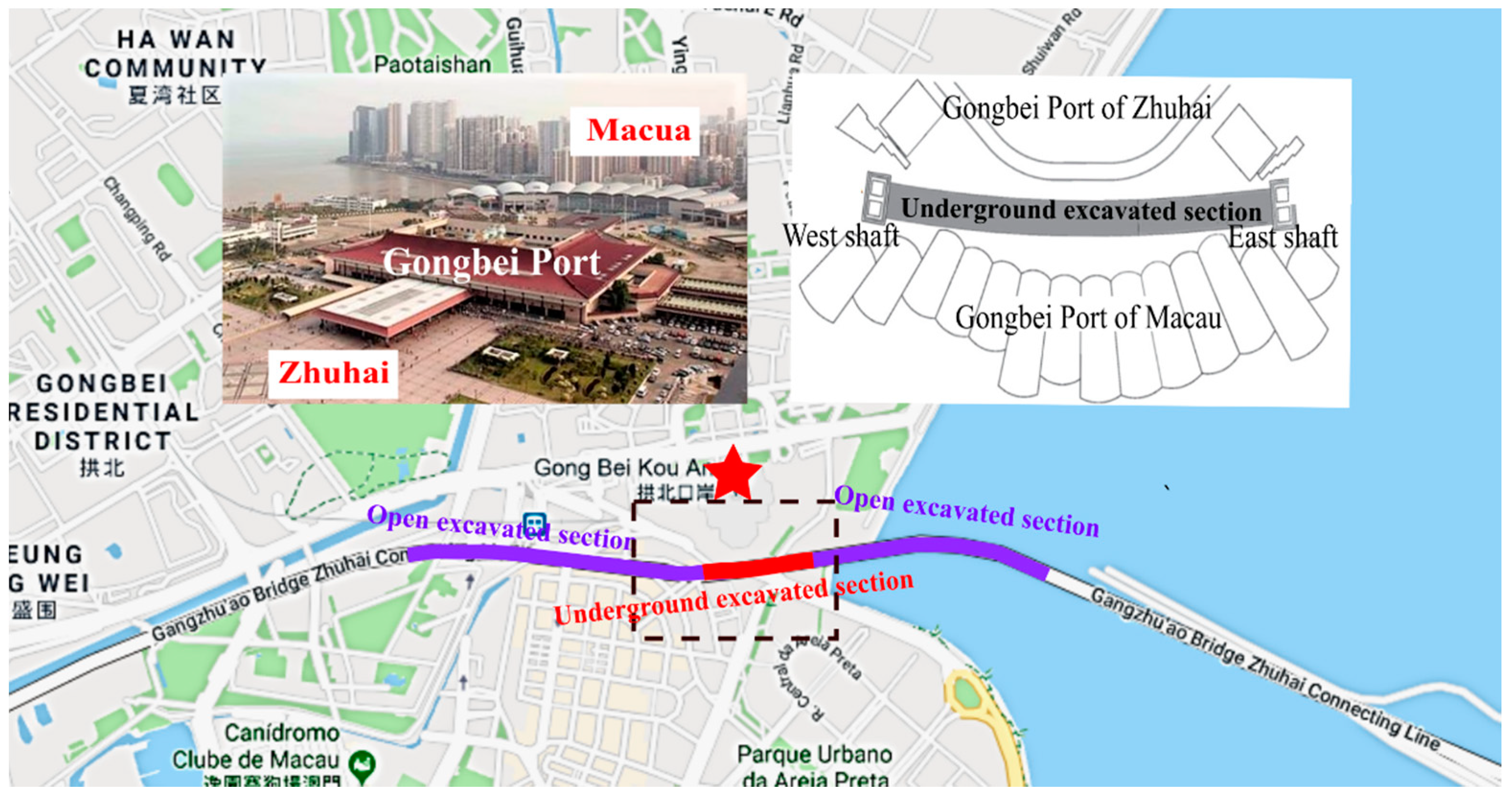
The Gongbei tunnel, key engineering of the China Mainland section of the Hongkong-Zhuhai-Macao Bridge project, which crosses beneath the largest land port of China, named “Gongbei Port”. As shown in
Figure 1, it connects the Gongbeiwan Bridge and the Guangdong public security border fifth detachment Maoshengwei administrative zone, which include an open excavated section in the sea (S1), an underground excavated section at the Port (S2), and an open excavated section on land (S3) with lengths of 1224, 255, and 1229 m, respectively.
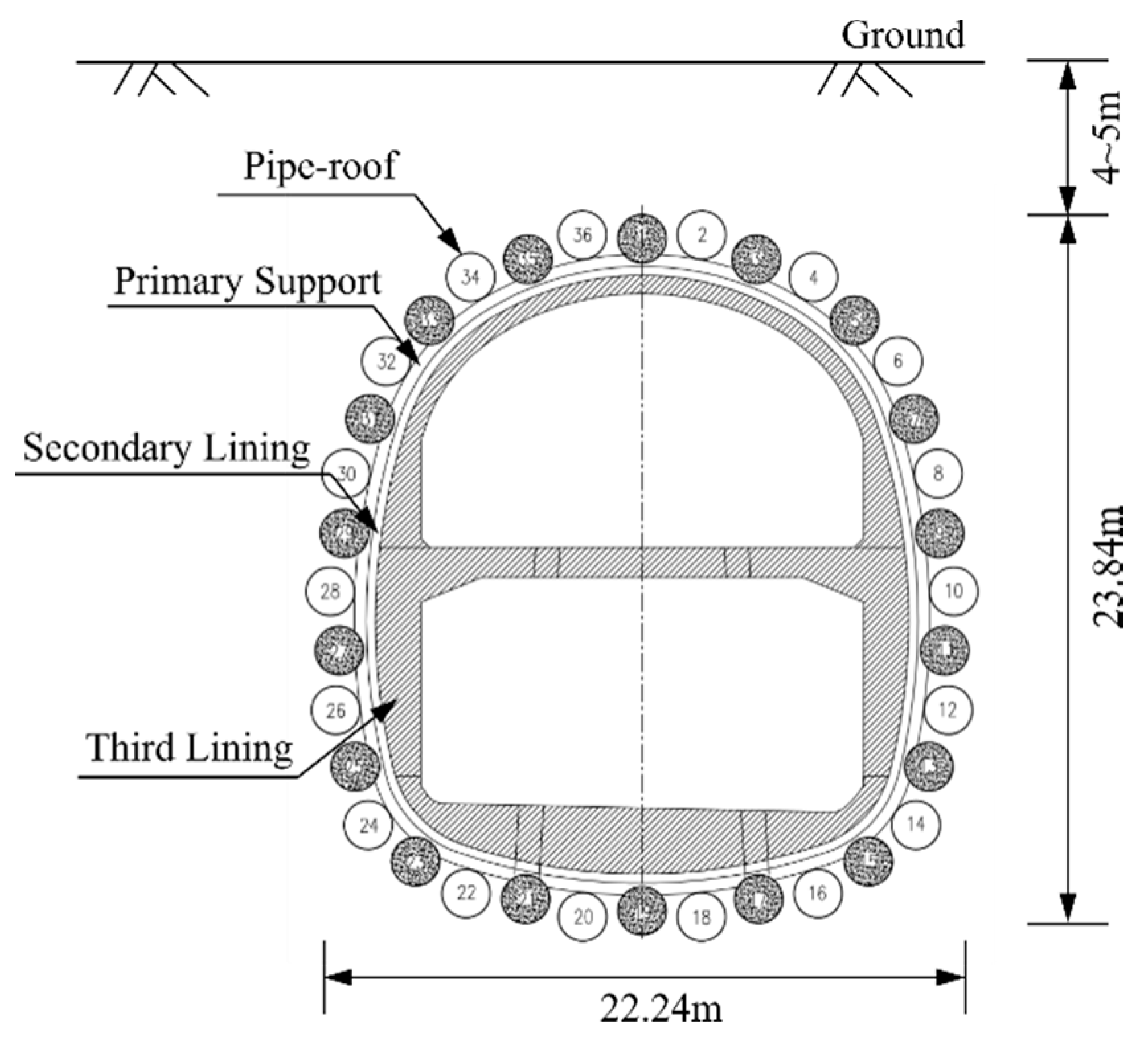
The S2 tunnel is the most critical part of the Gongbei tunnel, which has a service life of more than 100 years. As shown in
Figure 2, it traverses under the restricted area of the port with the pipe roof and soil freezing underground excavation method [
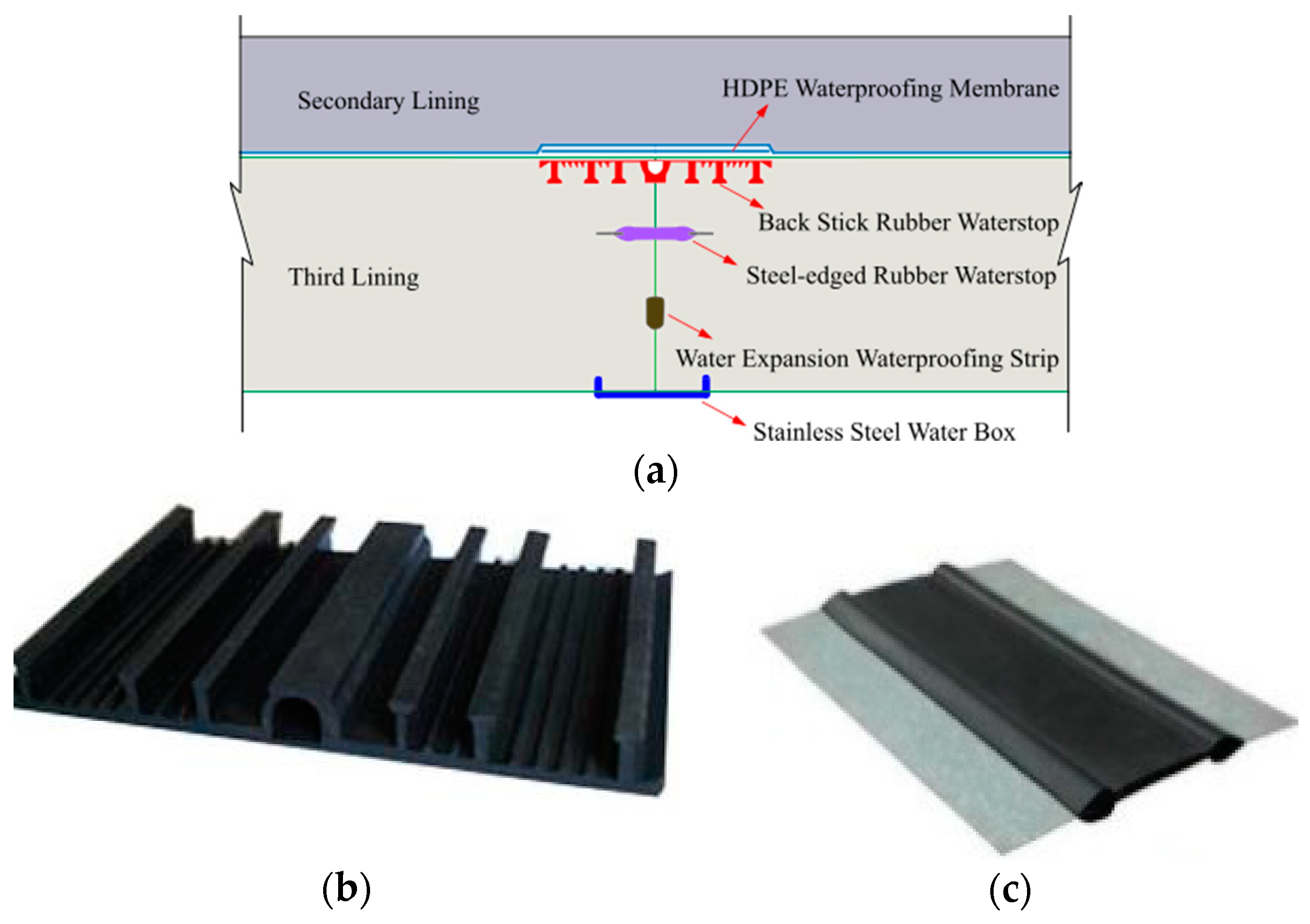
16], and the cross-section is designed as an egg shape, which is double-deck and symmetrical. Two movement joints are arranged on both sides of the S2 tunnel. The distance between the two movement joints on the east side to the east shaft is 34.4 and 70.1 m, respectively. The distance between the two movement joints on the west side to the west shaft is 36.9 and 72.6 m, respectively. In addition to the high-density polyethylene waterproofing membrane prelaid between the second lining and third lining, four waterproofing measures are adopted for the tunnel movement joints, which are back-sticked rubber water stop, steel-edged rubber water stop, water expansion waterproofing strip, and stainless-steel waterproofing box (
Figure 3).
The construction area of the S2 tunnel has a large water head (more than 0.3 MPa at the bottom of the tunnel) and abundant water sources, and it is likely that the seawater will leak into the supporting system. Because of the strong corrosiveness of seawater, the safety, and durability of the tunnel structure will be seriously affected when the leakage occurs. Compared with the established subsea tunnel, the S2 tunnel has the following characteristics: (1) the engineering geological and hydrological conditions of the tunnel site are extremely complicated. The soil stratum along the tunnel comprise muck, silty clay, mucky soil, and coarse sand. The groundwater is mainly found in gray-black silt, medium sand, coarse sand, gravel, sand and sand mixed silt soil [
17]. (2) It crosses beneath a restricted area of Gongbei Port, which is politically sensitive. In order to ensure normal customs clearance during the construction process, high requirements are placed on environmental protection and deformation control [
16]. (3) The cross-sectional area of excavation is 344.8 m
2 [
18,
19], which is about 10 times that of the ordinary subway tunnel. The tunnel structure is complicated, which makes the waterproof structure is challenging to be constructed.
3. Design of the Model Test
3.1. Design of the Test Scheme
In order to simplify the model, two assumptions of a homogeneous formation and no tidal action of seawater were made in the model. The similarity theories are the theoretical basis of model testing [
20], and the model test was designed, loaded, and organized according to a set of similar requirements associated with the model and prototype. To investigate the mechanical characteristics of the lining and movement joints under the fluid-soil coupling effects, we obtained the similarity criteria through the dimensional analysis method. According to the dimensional analysis method, kg (
M), m (
L), and s (
T) were selected as the basic dimensions, and three independent physical quantities were selected at the same time. The dimension coefficient matrix of geometric dimension (
l), unit weight (
γ), and permeability coefficient (
k) is shown in Equation (1):
These three physical quantities were taken as fundamental physical quantities, and the formulas for calculating the similarity constants of each physical quantity obtained according to the π theorem are provided in
Table 1 [
21,
22].
The cross-sectional dimensions of the prototype project are 18.8 m in width and 20.6 m in height. Due to the limitation of the test space, the width and the height were set to 0.47 and 0.51 m in the test model, respectively. Thus, the geometric similarity scale
αl was deduced using Equation (2) [
23,
24]:
where physical variables marked with subscript
p were used to describe the project prototype and physical variables marked with subscript
m were used for the test model.
αl,
lp,
lm denote the similarity scale of geometry, the dimensions of the test model, and the dimensions of the project prototype, respectively. The similarity constants of physical quantities obtained according to the similarity criteria are provided in
Table 2.
3.2. Materials of the Model Test
As shown in
Figure 4, in order to obtain larger structural deformation and avoid the reading error, the plexiglass with a thickness of 1.5 cm was adopted to simulate the third lining of the prototype project in the model. The elastic modulus of plexiglass at 14 °C is 2760.2 MPa, which is about 1/10 of that of concrete and meets the test requirements. The tunnel model consists of two sections, which are connected by rubber to simulate the movement joint. A thickened double-plastic film was adopted to simulate the waterproof board.
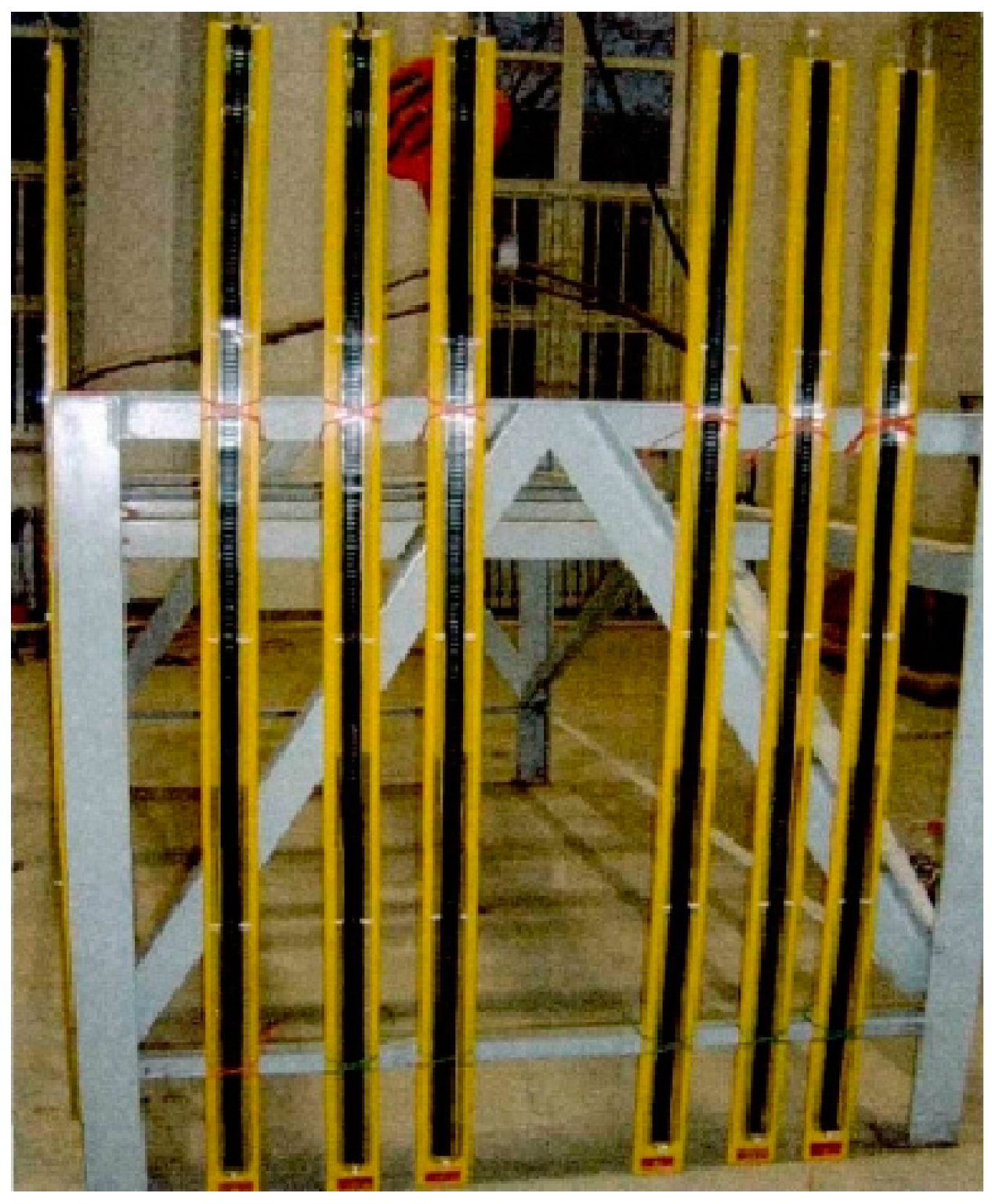
Thirty-six PVC pipes with a diameter of 5 cm were filled with cement mortar and adopted to simulate the pipe curtain. The grouting material was made of cement and soil, which fills the gap among the PVC pipes.
To simulate the silty clay layer of the prototype, the mixed material whose physical quantities meet the similarity constants was obtained by adding barite, calcium–magnesium powder, talc, and other materials. The physical and mechanical parameters of the mixed material were determined by geotechnical tests, as shown in
Table 3. In the prototype project, the thickness of the covering soil is 5 m. According to the geometric similarity scale, the thickness of the covering soil is 0.125 m in the model test.
3.3. Equipment of the Model Test
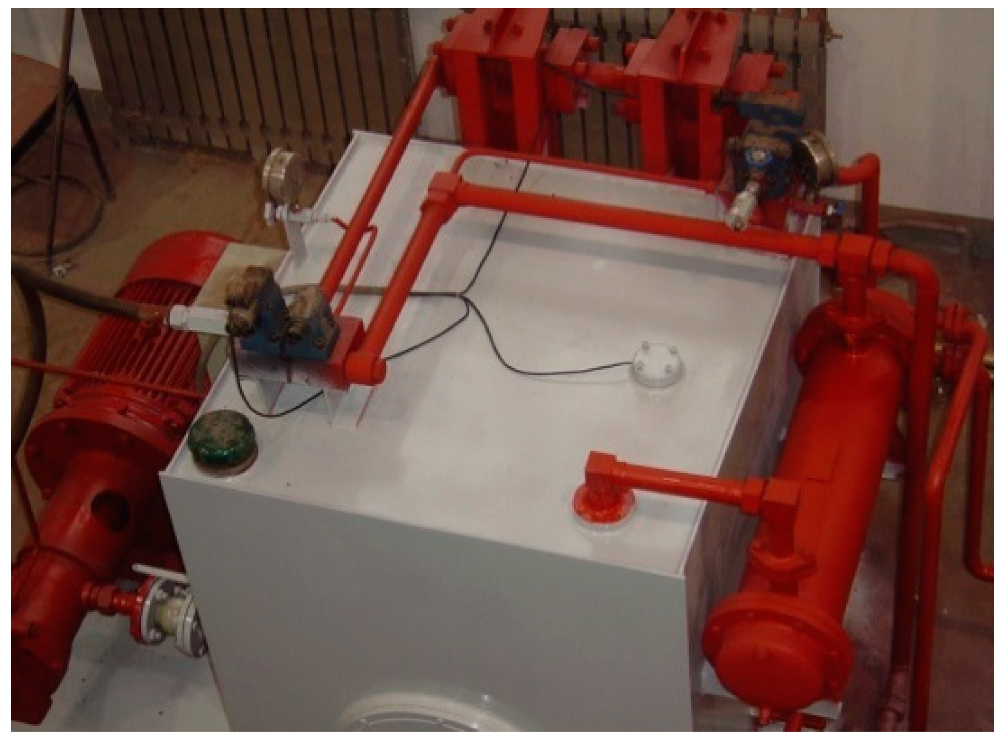
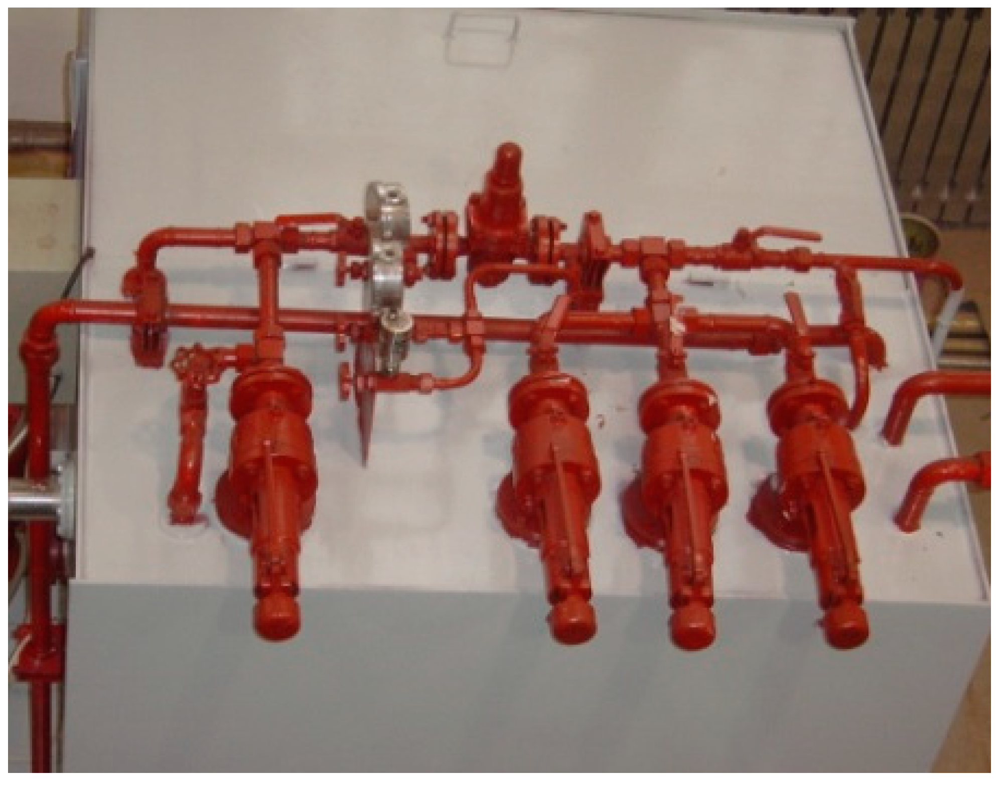
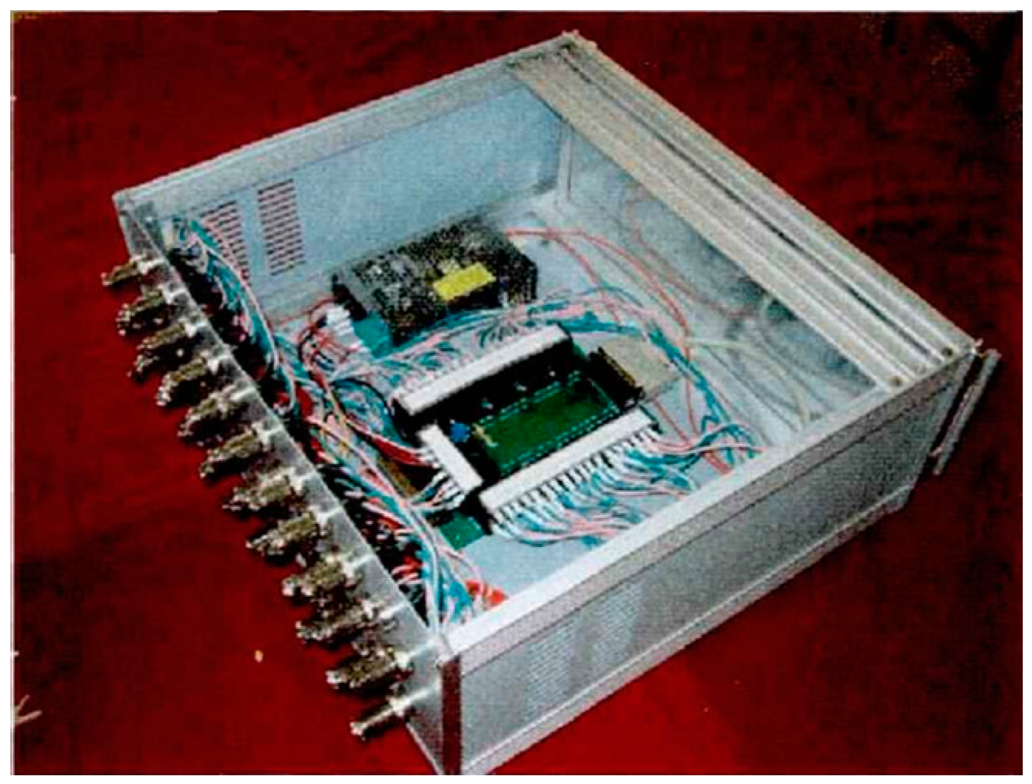
The model test system adopted in this test is developed by the Tunnelling and Underground Engineering Research Center of Beijing Jiaotong University, which can simultaneously apply water pressure and earth pressure. The size of the model test bench is 260 cm × 100 cm × 180 cm. Two hydraulic jacks were installed in the horizontal direction, and four hydraulic jacks were installed in the vertical direction. The bearing capacities in the vertical direction and horizontal direction are 2000 and 1000 kN, respectively. The test equipment consists of a hydraulic control system, a water pressure loading system, a data acquisition system, and a reaction frame, as shown in
Figure 5,
Figure 6,
Figure 7 and
Figure 8. In the test, the strain and water pressure were measured by a fiber Bragg grating (FBG) sensor and a U-type mercury pressure gauge, respectively.
3.4. Test Procedures
First, the two sections of the lining were connected by the rubber, as well as a group of FBG sensors and water pressure test points were installed on the lining and movement joint, respectively. Second, two sections of the lining were wrapped with plastic plates according to the PWW and FWW methods, respectively. After the completion of the above, the mixed material with a thickness of 1 m was set on the test bench. The tunnel model was positioned accurately, and the side plates of the test bench were installed and sealed. A grouting circle with 36 PVC pipes was installed, and the mixture material was filled to 0.125 m higher than the top of the model after that. By layered compacting, the mixed material was filled into the test bench. Finally, the top cover of the test bench was installed and sealed. According to the test scheme, the water pressure and drainage discharge set in each experimental group are shown in
Table 4. By taking the first group (1#) as an example, the water pressure of 0.75 kPa was applied in the undrained state. Then, the strain and the water pressure were monitored.
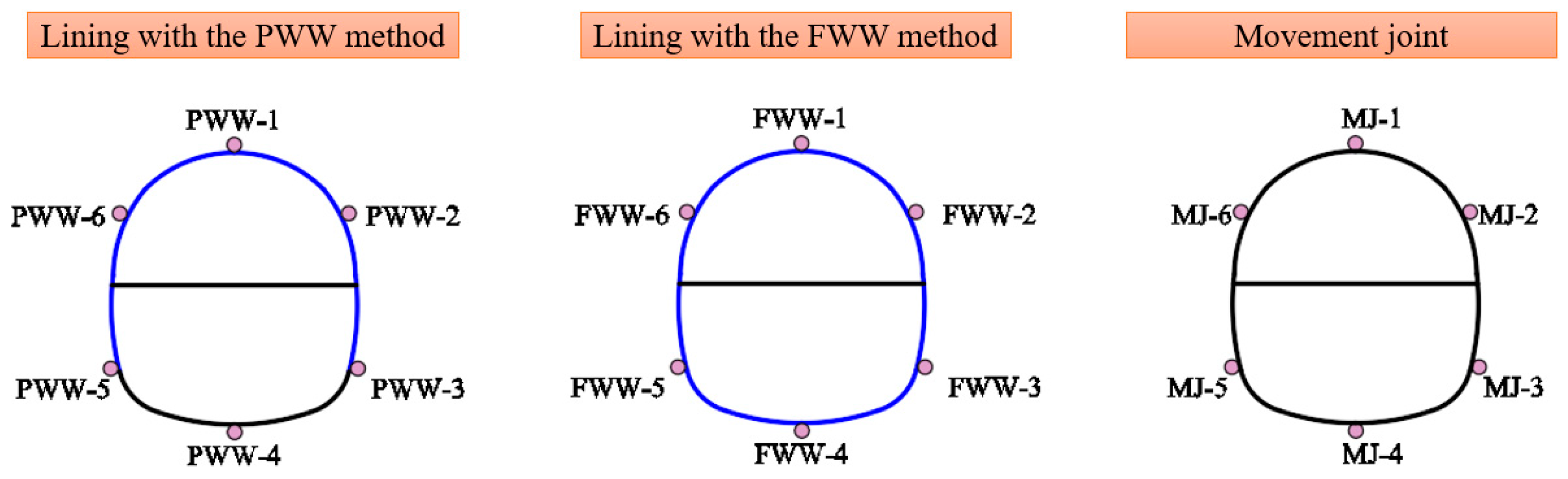
Figure 9 and
Figure 10 illustrate the position of measuring points. Eighteen measuring points for water pressure were arranged around the lining and the movement joint, respectively. Forty measuring points for strain were arranged on both sides of the lining and the outside of the movement joint, respectively.
4. Result
4.1. Mechanical Characteristics of Lining
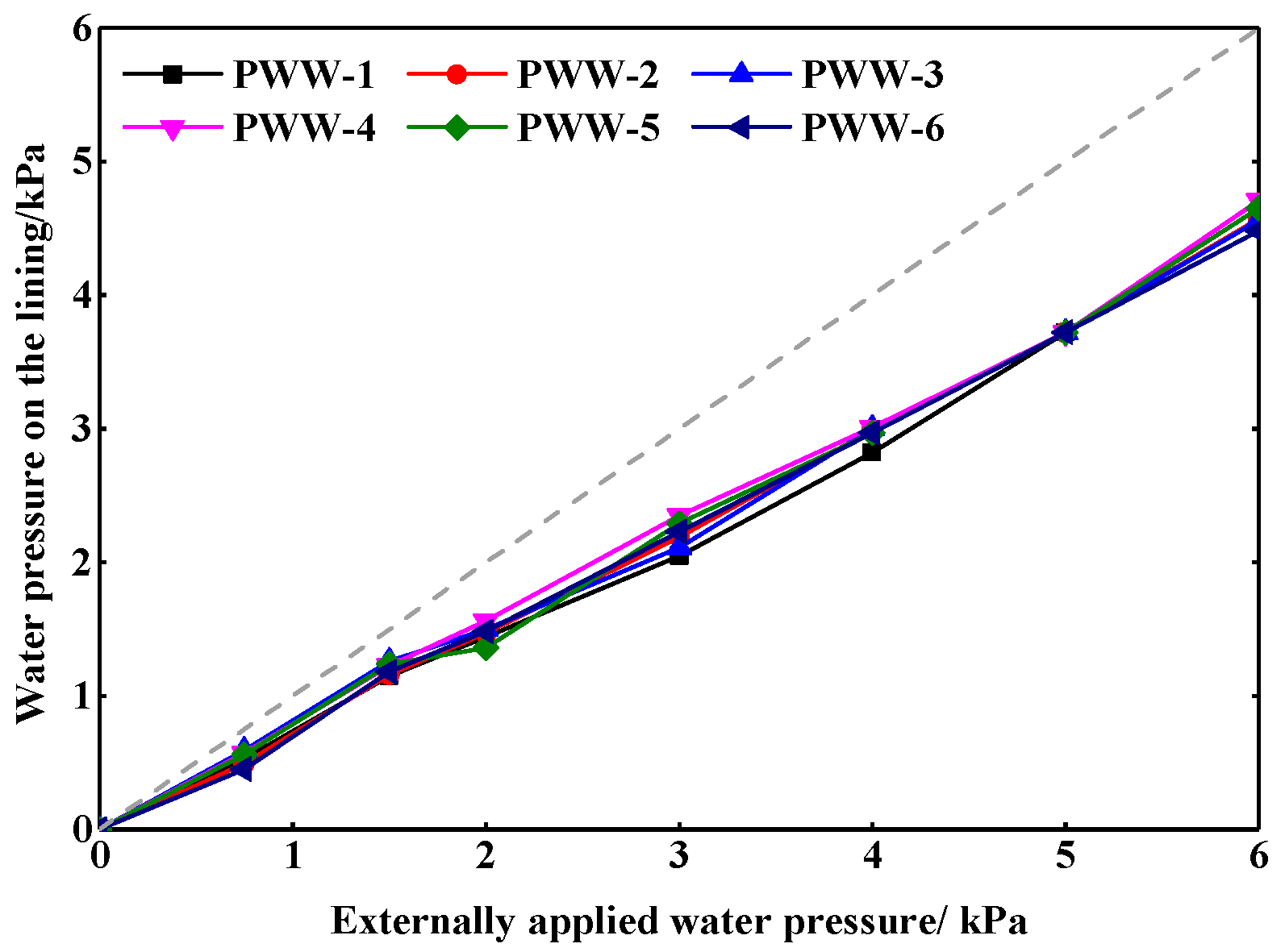
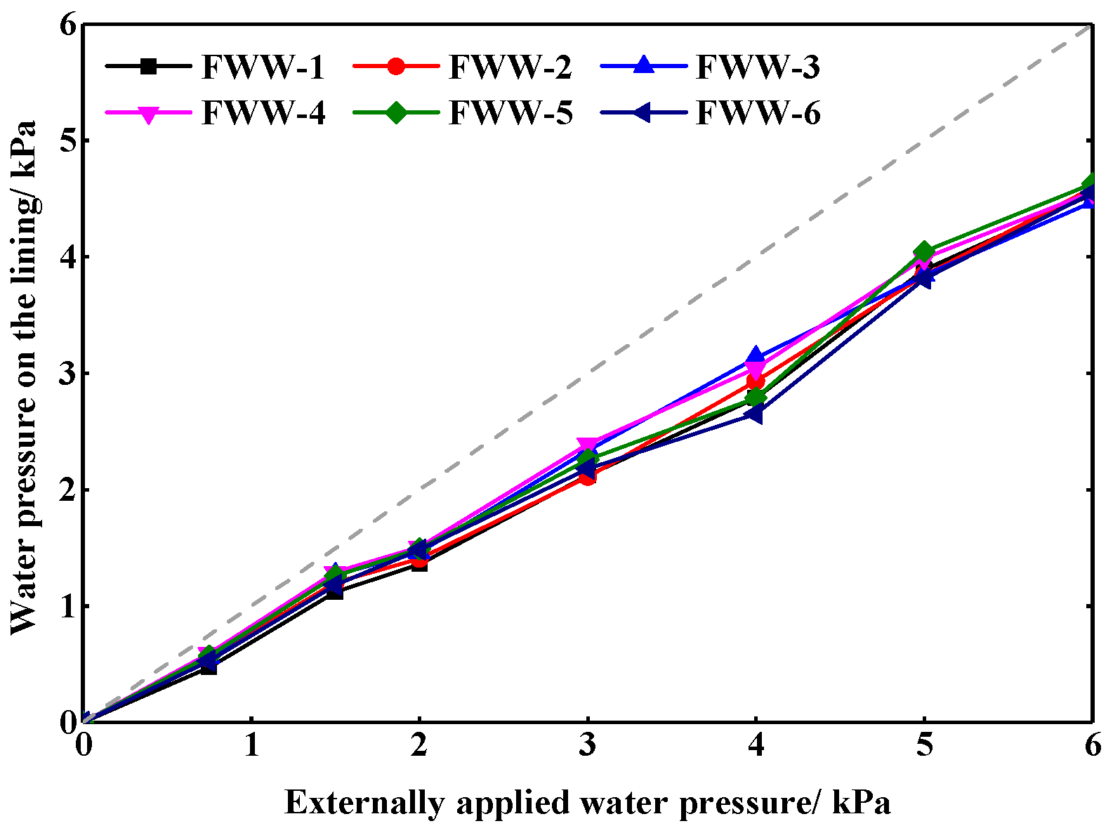
Figure 11 and
Figure 12 show the variation of water pressures on the lining with the PWW method and the FWW method under the undrained state, respectively. There is no significant difference in the variation and distribution of the water pressure on the lining with the different waterproof methods in the undrained state. With the increase of the external water pressure, the water pressure on the lining increased linearly. Moreover, the water pressure on each monitoring point was 5/6 of the water pressure externally applied. It indicates that the pipe curtain and grouting layer bore part of the water pressure for the lining. In addition, the water pressure at each position of the tunnel was close, which indicates that external water pressure was applied to the lining uniformly under the undrained state.
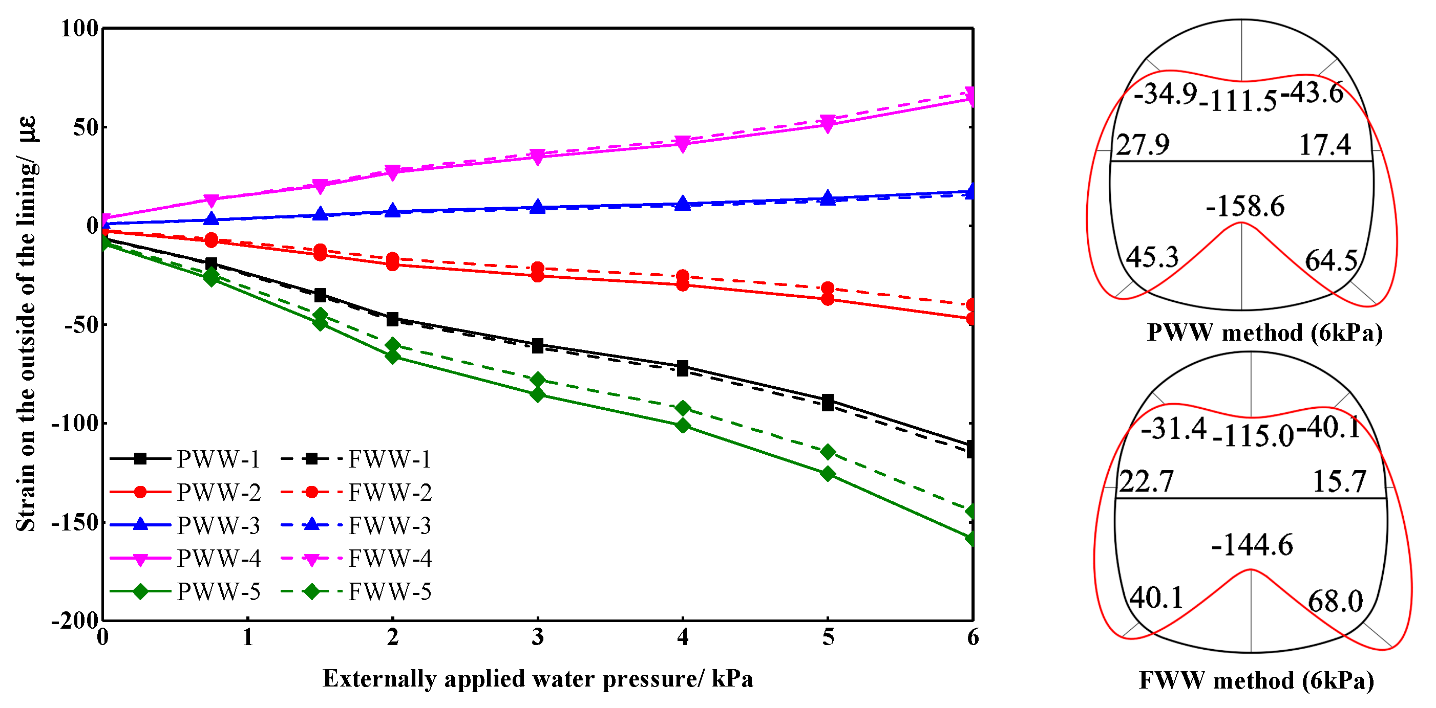
Figure 13 and
Figure 14 show the variation and distribution of strain on the lining with the PWW method and the FWW method under the undrained state, respectively. In figures, positive values represent tensile strains and negative values represent compressive strains. It is worth mentioning that the strain distributions under different external water pressures were similar, so only the strain distribution diagram with the external water pressure of 6 kPa is shown. With the increase of external water pressure, the strain on both sides increased linearly. The distribution of strain was symmetrical. The top and bottom of the lining were deformed inward while the left and right sides were deformed outward. The maximum tensile strain of lining appeared on the inner surface of the invert, and the tensile strain on the outer surface of the arch springing and the inner surface of the vault was also large. The maximum compressive strain of lining appeared on the inner surface of the invert.
Figure 15,
Figure 16,
Figure 17 and
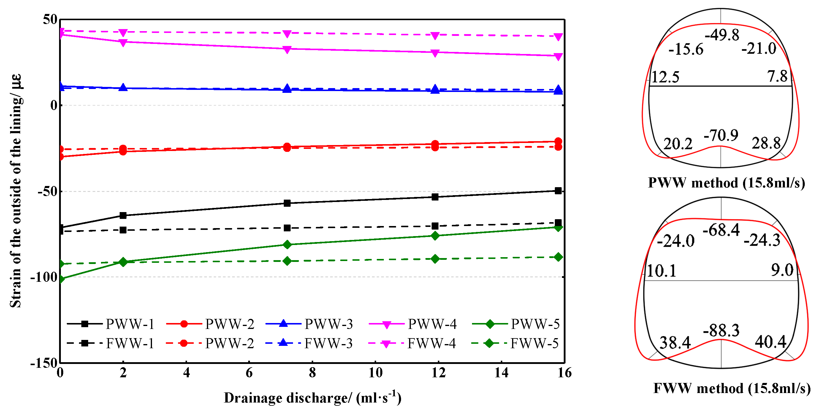
Figure 18 show water pressure and strain on lining under the drained state between the different waterproof methods. In testing, the external water pressure of 4 kPa was applied to the model, while the drainage pipes of the section with the FWW method were kept undrained and the drainage pipes of the section with the PWW method were opened. Four drainage discharge, 2.0, 7.2, 11.9, and 15.8 mL/s, were set, respectively, of which 15.8 mL/s was the corresponding drainage discharge when the pipes were freely drained.
As the drainage discharge increased, the water pressure on the lining with the FWW method decreased slightly. The maximum decrease (13.7%) was found at the sidewall (FWW-5), while the minimum decrease (3.7%) was found at the vault (FWW-1). In contrast, the water pressure on the lining with the PWW method decreased more with the increase of the drainage discharge. Even with a small drainage discharge, the water pressure on the sidewall and the invert decreased significantly. The maximum decrease (36.8%) was found at the sidewall (PWW-5), while the minimum decrease (17.4%) was found at the vault (PWW-1). It should be pointed out that the water pressure on the lining with the FWW method should be equal to the hydrostatic pressure in theory and would not decrease with the increase of the drainage discharge. However, it is impossible to completely isolate the hydraulic connection between the two sections of lining due to the limitation of the test conditions. Therefore, a decrease in the water pressure was found in the lining with the FWW method.
The distribution of the strain under the drained state was similar to that under the undrained state. The maximum and minimum strains of the two sections were found at the invert and arch springing, respectively. As the drainage discharge increased, the strain on the lining with the FWW method kept roughly constant while that with the PWW method decreased. When the pipes were freely drained, the strain on each position got a discount of about 30%. It indicates that the FWW method is helpful to reduce the water pressure and strain on the lining under the drained state.
4.2. Mechanical Characteristics of the Movement Joint
Movement joints are the weak part of tunnel waterproof, and the excessive water pressure will lead to leakage of the movement joints.
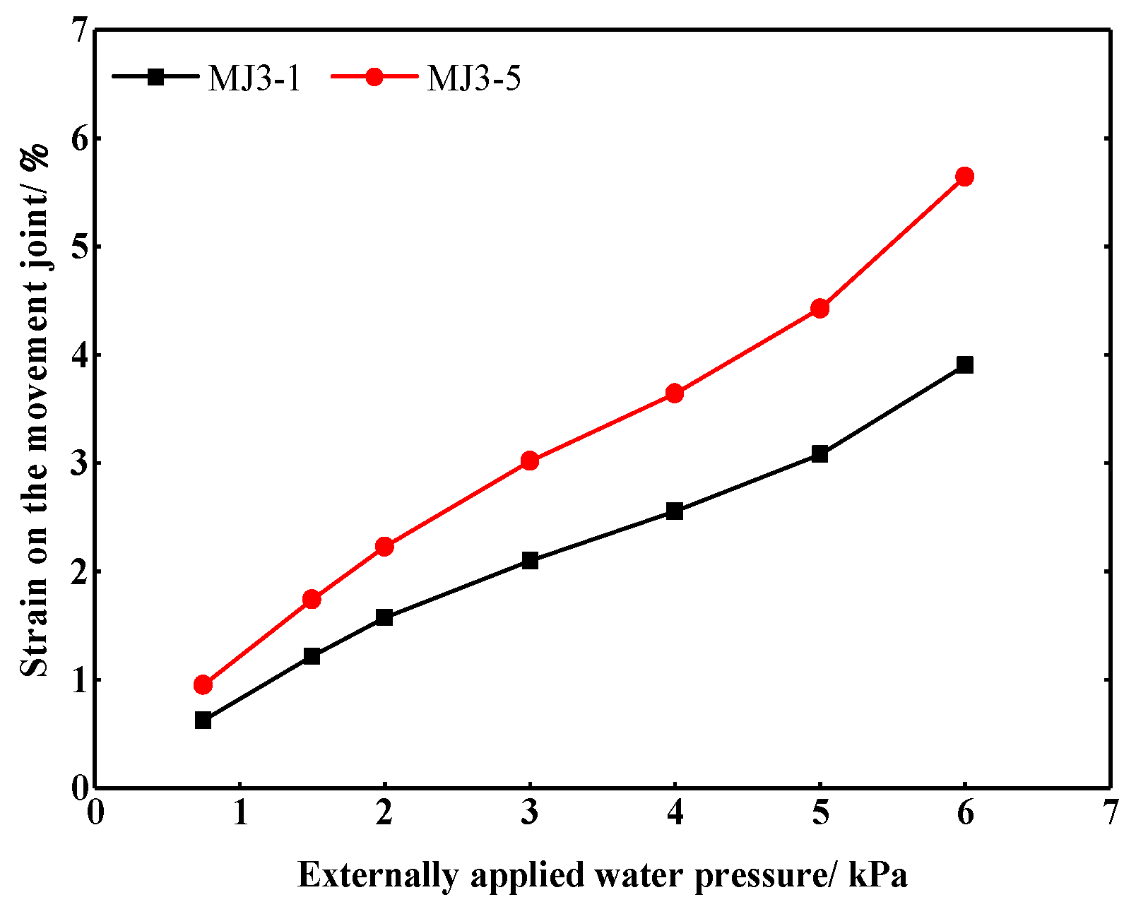
Figure 19 shows the strains on the vault and invert of the movement joint under the undrained state. As the external water pressure increased, the strain on the movement joint increased almost linearly, which shows that the movement joint was in the elastic strain stage. In the process of increasing the externally applied water pressure, no leakage occurred at the movement joint, which indicates that the movement joint material has a good sealing performance. The growth rate of strain on the invert was larger than that on the vault, and the strain on the invert was larger than that on the vault by over 40% in the same external water pressure. It thus says that more attention should be paid to the waterproof of the invert of movement joints in the construction process.
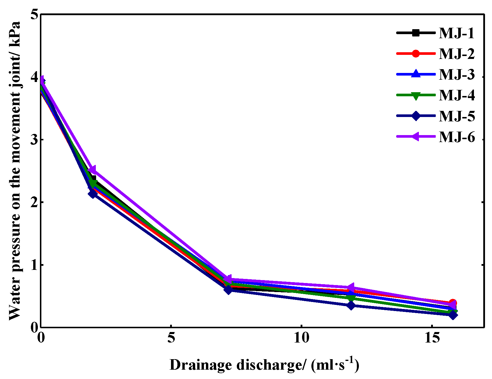
Figure 20 shows the variation of the water pressure on the movement joint in the external water pressure of 4 kPa. The water pressure on the movement joint decreased rapidly with the increase of the drainage discharge, and when the drainage discharge reached 7.2 mL/s, the rate of decrease became slower. Finally, the water pressure was close to 0. Under the same drainage discharge, the water pressures on the invert and near the drainage pipes were smaller than that on other positions. In general, there was no significant difference in the water pressure at each monitoring point.
5. Conclusions
Based on the Gongbei tunnel in Guangdong Province, China, this study established a scale model. The comparative test sections of the FWW method and the PWW method were set up, respectively, and a movement joint was arranged between the two sections. By changing the externally applied water pressure and drainage discharge, the variation and distribution of the water pressure and strain of the lining with different waterproof methods were investigated. Moreover, the variation and distribution of the water pressure and strain of the movement joint were studied. The main findings of this study could be summarized as follows:
(1) When a near-sea tunnel is designed to be undrained, the water pressures on the linings with the PWW method and the FWW method cannot be reduced, and the distribution and value of the strain of the lining in two waterproof methods have no significant difference. With the increase of the external water pressure, the water pressure and the strain on the lining increased linearly. Therefore, if the waterproof and drainage of tunnel engineering are mainly based on water blocking, it is recommended to adopt the PWW method because of its economic advantages. Moreover, grouting layer plays an important role in reducing the water pressure on the lining.
(2) When a near-sea tunnel is designed to be drained, the water pressures on the linings with the PWW method and the FWW method decrease with the increase of the drainage discharge. The PWW method has a greater reduction in water pressure. The maximum and minimum decreases were found at the sidewall (36.8%) and vault (17.4%), respectively. Compared with the FWW method, the lining with the PWW method has a smaller strain and more reasonable stress. Under the state of free drainage, the strain on the lining with the PWW method may get a discount of about 30%, the maximum and minimum tensile strains were found at the invert (70.9 με) and arch springing (7.8 με), respectively. Therefore, if the waterproof and drainage of tunnel engineering are mainly based on water discharging, it is recommended to adopt the PWW method.
(3) As the external water pressure increased, the strain on the movement joint increased almost linearly. The growth rate of strain on the invert was larger than that on the vault, and the strain on the invert was larger than that on the vault by over 40% in the same external water pressure. Therefore, more attention could be paid to the waterproof of the movement joints in the construction process, especially the invert. The water pressure of the movement joint decreases with the increase of the drainage discharge, but the rate of decrease gradually slows down until it is close to 0. The water pressures on the invert and near the drainage pipes are smaller than that on other positions.
6. Discussion
This paper made some preliminary conclusions about the mechanical characteristics of waterproof system for near-sea tunnel, but it should be noted that the two simplifications in the model of a homogeneous formation and no tidal action of seawater were made. In fact, the water head is affected by tidal action, and different stratum has different permeability coefficient. Therefore, some differences will exist between the field and test results. For example, whether the stress on the lining increases linearly with the increase of the external water head in undrained state and whether the distribution of the stress and water pressure on the lining are symmetrical. These are not yet known and will be discussed in future studies by field test.
Author Contributions
Conceptualization, Z.Z. and Z.T.; data curation, Q.L.; funding acquisition, Z.T.; investigation, Q.L.; software, J.Z.; supervision, Z.T.; validation, J.Z.; writing—original draft, Z.Z.; writing—review and editing, Z.D. All authors have read and agreed to the published version of the manuscript.
Funding
The authors acknowledge the National Natural Science Foundation of China (Grant No. 51678034).
Conflicts of Interest
The authors declare no conflict of interest.
References
- Wang, M.S. Current developments and technical issues of underwater traffic tunnel—Discussion on construction scheme of Taiwan strait undersea railway tunnel. Chin. J. Rock Mech. Eng. 2008, 27, 2161–2172. (In Chinese) [Google Scholar]
- Lv, M.; GrΦv, E.; Nilsen, B.; Melby, K. Norwegian experience in subsea tunnelling. Chin. J. Rock Mech. Eng. 2005, 24, 4219–4225. (In Chinese) [Google Scholar]
- Wang, M.S.; Huang, M.F. Key problems on subsea tunnel construction. J. Archit. Civ. Eng. 2007, 11, 1–4. (In Chinese) [Google Scholar]
- Chabot, J.D.S.; Sandrone, F.; Gamisch, T. The importance of drainage system in railway tunnels and possibilities to reduce the LCC. In World Tunnel Congress; WTC: Geneva, Switzerland, 2013. [Google Scholar] [CrossRef]
- Li, P.F.; Liu, H.C.; Zhao, Y.; Li, Z. A bottom-to-up drainage and water pressure reduction system for railway tunnels. Tunn. Undergr. Space Technol. 2018, 81, 296–305. [Google Scholar] [CrossRef]
- Wang, X.Y.; Tan, Z.S.; Wang, M.S.; Zhang, M.; Huang, M.F. Theoretical and experimental study of external water pressure on tunnel lining in controlled drainage under high water level. Tunn. Undergr. Space Technol. 2008, 23, 552–560. [Google Scholar] [CrossRef]
- Farhadian, H.; Katibeh, H. New empirical model to evaluate groundwater flow into circular tunnel using multiple regression analysis. Int. J. Min. Sci. Technol. 2017, 27, 415–421. [Google Scholar] [CrossRef]
- Wang, X.Y.; Wang, M.S.; Zhang, M. Simple method to calculate tunnel discharge and external water pressure on lining. J. North. Jiaotong Univ. 2004, 28, 8–10. (In Chinese) [Google Scholar] [CrossRef]
- Kolymbas, D.; Wagner, P. Groundwater ingress to tunnels—The exact analytical solution. Tunn. Undergr. Space Technol. 2007, 22, 23–27. [Google Scholar] [CrossRef]
- Li, Z.; He, C.; Ding, J.J.; Yang, S.Z. A method to predict the relationship between water discharge and pressure during operational period of city tunnels constructed using the mining method. Eng. Mech. 2017, 34, 14–21. (In Chinese) [Google Scholar]
- Nam, S.W.; Bobet, A. Radial deformations induced by groundwater flow on deep circular tunnel. Rock Mech. Rock Eng. 2007, 40, 23–39. [Google Scholar] [CrossRef]
- Nam, S.W.; Bobet, A. Liner stresses in deep tunnels below the water table. Tunn. Undergr. Space Technol. 2006, 21, 626–635. [Google Scholar] [CrossRef]
- Xu, J.H.; He, C.; Xia, W.Y. Research on coupling seepage field and stress field analyses of underwater shield tunnel. Rock Soil Mech. 2009, 30, 3519–3527. (In Chinese) [Google Scholar] [CrossRef]
- Sun, J.D. Study on waterproof technology of subway engineering. Constr. Technol. 2008, 37, 22–24. (In Chinese) [Google Scholar]
- Guo, D.Y. Overview of waterproofing technology in mass transit engineering. China Build. Waterproofing 2010, S1, 48–54. (In Chinese) [Google Scholar]
- Liu, J.G.; Ma, B.S.; Cheng, Y. Design of the Gongbei tunnel using a very large cross-section pipe-roof and freezing method. Tunn. Undergr. Space Technol. 2018, 72, 28–40. [Google Scholar] [CrossRef]
- Liu, J.G. Construction Documents Design to Key Project of Gongbei Tunnel about Zhuhai Connecting Line of Hong Kong-Zhuhai-Macao Bridge; CCCC seceond highway consultants Co.Ltd: Wuhan, China, 2013.
- Zhang, P.; Ma, B.S.; Zeng, C.; Xie, H.M.; Wang, D.W.; Li, X. Steel curved pipe jacking construction under complicated conditions for a curved pipe roof. In Pipelines 2016; ASCE: New York, NY, USA, 2016; pp. 1820–1829. [Google Scholar] [CrossRef]
- Li, J.; Liu, Z.G.; Zhang, P. The hugest curved jacking pipe roof tunnel of Hong Kong-Zhuhai-Macao bridge. In International Conference on Pipelines and Trenchless Technol 2014; ASCE: New York, NY, USA, 2014; pp. 422–431. [Google Scholar] [CrossRef]
- Buckingham, E. On physically similar systems; illustrations of the use of dimensional equations. Phys. Rev. 1914, 4, 345–376. [Google Scholar] [CrossRef]
- Islam, M.R.; Ali, S.M.F. New Scaling Criteria for Polymer, Emulsion And Foam Flooding Experiments. J. Can. Pet. Technol. 1989, 28, 79–87. [Google Scholar] [CrossRef]
- Chen, H.; Sun, J.; Lv, Y. Modelling experiments and studies on complex lining of tunnels in incompetent strata. Chin. J. Rock Mech. Eng. 1997, 16, 162–170. (In Chinese) [Google Scholar]
- Zhang, P. Model Test Research on the Distribution Law of Water Pressure upon Lining and the Stress Characteristics of Lining Structure in Subject to Subsea Tunnel. Master’s Thesis, Beijing Jiaotong University, Beijing, China, 2008. (In Chinese). [Google Scholar]
- Tan, Z.S.; Zeng, C.; Li, J.; Du, C.W.; Zhang, P. Model test investigation on the mechanical characteristics of support structure of subsea tunnels. China Civ. Eng. J. 2011, 44, 99–105. (In Chinese) [Google Scholar] [CrossRef]
Figure 1.
Route plan of the Gongbei Tunnel.
Figure 1.
Route plan of the Gongbei Tunnel.
Figure 2.
Cross-section of the Gongbei tunnel.
Figure 2.
Cross-section of the Gongbei tunnel.
Figure 3.
Waterproof structure of the movement joint. (a) Section of the waterproof structure, (b) back-sticked rubber water stop, and (c) steel-edged rubber water stop.
Figure 3.
Waterproof structure of the movement joint. (a) Section of the waterproof structure, (b) back-sticked rubber water stop, and (c) steel-edged rubber water stop.
Figure 4.
Model of the Gongbei tunnel. (a) Lining, (b) movement joint, and (c) waterproof board.
Figure 4.
Model of the Gongbei tunnel. (a) Lining, (b) movement joint, and (c) waterproof board.
Figure 5.
Hydraulic control system.
Figure 5.
Hydraulic control system.
Figure 6.
Water pressure loading system.
Figure 6.
Water pressure loading system.
Figure 7.
Data acquisition system.
Figure 7.
Data acquisition system.
Figure 8.
U-type mercury pressure gauge.
Figure 8.
U-type mercury pressure gauge.
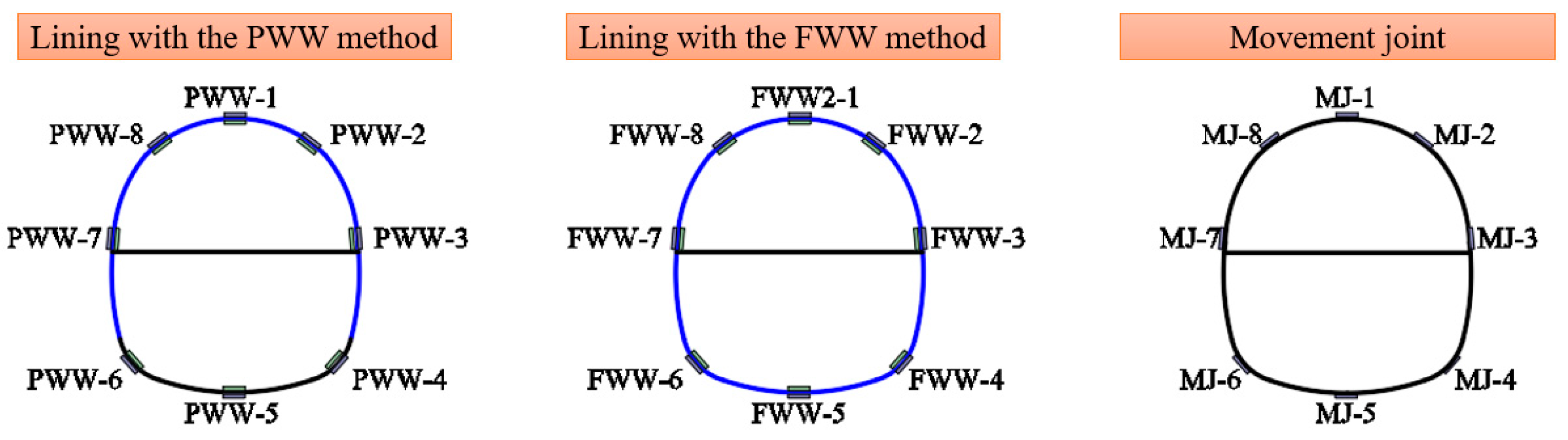
Figure 9.
Location of the measuring points for the water pressure (left schematic for lining with the partially wrapped waterproof (PWW) method, middle schematic for lining with the fully wrapped waterproof (FWW) method, and right schematic for movement joint).
Figure 9.
Location of the measuring points for the water pressure (left schematic for lining with the partially wrapped waterproof (PWW) method, middle schematic for lining with the fully wrapped waterproof (FWW) method, and right schematic for movement joint).
Figure 10.
Location of the measuring points for the strain (left schematic for lining with the PWW method, middle schematic for lining with the FWW method, and right schematic for movement joint).
Figure 10.
Location of the measuring points for the strain (left schematic for lining with the PWW method, middle schematic for lining with the FWW method, and right schematic for movement joint).
Figure 11.
Water pressure on the lining with the PWW method under the undrained state.
Figure 11.
Water pressure on the lining with the PWW method under the undrained state.
Figure 12.
Water pressure on the lining with the FWW method under the undrained state.
Figure 12.
Water pressure on the lining with the FWW method under the undrained state.
Figure 13.
Strain on the outside of the lining under the undrained state.
Figure 13.
Strain on the outside of the lining under the undrained state.
Figure 14.
Strain on the inside of the lining under the undrained state.
Figure 14.
Strain on the inside of the lining under the undrained state.
Figure 15.
Water pressure on the lining with the PWW method under the drained state.
Figure 15.
Water pressure on the lining with the PWW method under the drained state.
Figure 16.
Water pressure on the lining with the FWW method under the drained state.
Figure 16.
Water pressure on the lining with the FWW method under the drained state.
Figure 17.
Strain on the outside of the lining under the drained state.
Figure 17.
Strain on the outside of the lining under the drained state.
Figure 18.
Strain on the inside of the lining under the drained state.
Figure 18.
Strain on the inside of the lining under the drained state.
Figure 19.
Strain of the movement joint under the undrained state.
Figure 19.
Strain of the movement joint under the undrained state.
Figure 20.
Water pressure on the movement joint under the drained state.
Figure 20.
Water pressure on the movement joint under the drained state.
Table 1.
Formulas for calculating similarity constants of physical quantities.
Table 1.
Formulas for calculating similarity constants of physical quantities.
| Physical Quantity | Symbol | Dimension | Formula |
|---|
| Geometric length | l | L | αl |
| Unit weight | γ | ML−2T−2 | αγ |
| Permeability coefficient | k | LT−1 | αk |
| Time | t | T | αt = αl/αk |
| Seepage quantity | Q | L3T−1 | αQ = αl2/αk |
| Stress | σ | ML−1T−2 | ασ = αγ·αl |
| Elasticity modulus | E | ML−1T−2 | αE = αγ·αl |
| Strain | ε | - | 1 |
| Internal friction angle | φ | - | 1 |
| Poisson’s ratio | μ | - | 1 |
Table 2.
Similarity constants of physical quantities.
Table 2.
Similarity constants of physical quantities.
| Physical Quantity | Unit Weight | Permeability Coefficient | Elasticity Modulus | Poisson’s Ratio |
|---|
| Similarity constants | 1 | 1 | 40 | 1 |
Table 3.
Physical and mechanical parameters of prototype and model.
Table 3.
Physical and mechanical parameters of prototype and model.
| Parameter | Scale | Unit Weight | Porosity Ratio | Elasticity Modulus | Permeability Coefficient |
|---|
| Prototype material | 20.6 m | 19.8 kN/m3 | 0.71 | 4.91 MPa | 1.82 × 10⁻³ cm/s |
| Model material | 0.51 m | 18.7 kN/m3 | 0.62 | 0.16 MPa | 2.00 × 10⁻³ cm/s |
| Ratio | 40 | 1.06 | 0.8 | 30.2 | 0.91 |
Table 4.
Experimental group.
Table 4.
Experimental group.
| Group No. | Combination | Influence Factors | |
|---|
| Water Pressure(A) (kPa) | Drainage Discharge(B) (mL/s) |
|---|
| 1# | A1B1 | 0.75 | 0 |
| 2# | A2B1 | 1.50 | 0 |
| 3# | A3B1 | 2.00 | 0 |
| 4# | A4B1 | 3.00 | 0 |
| 5# | A5B1 | 4.00 | 0 |
| 6# | A6B1 | 5.00 | 0 |
| 7# | A7B1 | 6.00 | 0 |
| 8# | A5B2 | 4.00 | 2 |
| 9# | A5B3 | 4.00 | 7.2 |
| 10# | A5B4 | 4.00 | 11.9 |
| 11# | A5B5 | 4.00 | 15.8 |
© 2020 by the authors. Licensee MDPI, Basel, Switzerland. This article is an open access article distributed under the terms and conditions of the Creative Commons Attribution (CC BY) license (http://creativecommons.org/licenses/by/4.0/).


