Abstract
This work presents a double asymmetric data hiding technique. The first asymmetry is created by hiding secret data in the complex region of the cover image and keep the smooth region unaffected. Then another asymmetry is developed by hiding a different number of secret bits in the various pixels of the complex region. The proposed technique uses the ant colony optimization (ACO) based technique for the classification of complex and smooth region pixels. Then, the variable least significant bits (VLSB) data hiding framework is used to hide secret bits in the complex region of the cover image. A distance-based substitution technique, namely increasing distance increasing bits substitution algorithm, is used to ensure the asymmetry in the number of hidden bits. The double asymmetric framework enhances the security of the hidden secret data and makes the retrieval of hidden information difficult for unauthorized users. The algorithm results in high-quality stego images, and the hidden information does not attract the human visual system (HVS).
1. Introduction
Steganography is the process of embedding secret information in a cover media including text, audio, image, and video files. All the mentioned cover mediums are important and play a vital role in securing secret information. However, the cover medium with a high level of redundancy is more suitable. Due to the high redundancy of digital images, we use the image as a cover medium to transmit secret information, embedded in the least significant bits (LSBs) of the pixels of the cover image. The steganography is used to save and secretly communicate the information. It has other exciting applications, e.g., copyright protection, data integrity assurance, and authentication of contents [1,2].
The data hiding techniques are explored by various forensics experts, and they proposed many useful steganographic techniques to improve security and protect the presence of hidden information to avoid access to the information from unintended parties. A couple of initial and famous data hiding techniques were presented by Honsinger et al. and Fridrich et al., exploiting the digital image pixel directly and hiding secret information in the pixels [3,4]. The techniques embedded fixed number secret information bits in the LSBs of the pixels of the cover image. However, fixed LSB information hiding techniques are weak, and the information hidden can be recovered easily if its presence is suspected. Therefore, it is better to use a variable number of LSB for data hiding. In such a case if an intruder got suspicious about the presence of information, it is difficult to recover the information. Using this idea, the data hiding in random LSB was used in [5]. Sahib et al. devised a variable least significant bits (VLSB) steganography technique. He implemented the VLSB steganography using modular distance technique (MDT) [6], decreasing distance decreasing bits algorithm (DDDBA) [7], varying index varying bits substitution (VIVBS) algorithm [8].
Lin et al., presented a reversible steganography technique using compressed images [9]. They designed a prediction method and judgment mechanism to successfully select the embeddable blocks during the data embedding phase and data extraction and recovery phase. The compressed images were used for watermarking and steganography [10,11]. The security of the hidden information was further ensured using block-based data hiding techniques, namely stego block chaining (SBC), enhanced stego block chaining (ESBC), and reversible enhanced stego block chaining (RESBC) techniques [12,13].
The main aim of steganographic techniques is to hide secret information in a cover medium in a way that its existence remains undetectable. The hidden information creates no noticeable variation [14] and does not attract the human visual system (HVS) [15]. The HVS has some limitations, as reported in the literature [16]. The HVS is more sensitive to changes introduced in the smooth region of the cover image relative to the complex region. Therefore, the modification introduced in the complex region is hard to be detected by HVS and makes the complex region of the cover image more suitable for data hiding. Hiding information in the complex region is initiated with the classification of the complex region and smooth region pixels and detect complex region pixels. The complex region pixels are used for information hiding while the smooth region pixels are left unaffected. Numerous ways, e.g., canny edge detection [17], Deriche [18], differential [19], Sobel [20], Prewitt [21], Roberts cross [22], and other, exist in the literature that can be used for this purpose. These methods are used to detect complex regions in digital images but, the performance of some of these techniques detect weak and disconnected edges, and the corresponding pixels are considered as part of the real complex region. The edges based information hiding using these techniques also subject some of those pixels that do not belong to edges to the information hiding process. This makes such an information hiding technique more sensitive to noise. In [23], Tian et al. proposed a new technique for edge detection. The methodology used ant colony optimization (ACO) for edge detection.
The techniques that hide information in the complex region of the cover image keep the smooth region of the cover medium unaffected or least affected. These steganography techniques include LSB methods [24], PVD methods, and side-match methods [24,25], and much detail are available in [26,27]. The hiding capacity of such techniques is minimal and small [23,25,28,29]. Ref. [30] used the ACO algorithm [31,32] for edge detection technique [23] combined with 4LSB substitution technique, for data hiding edges. The hiding technique results in high-quality stego images. However, due to the fixed 4 bits per pixel substitution, the ACO based data hiding in complex region technique [30] technique is easy to break. It becomes easy to retrieve the hidden information if an intruder gets access to the information related to the binary pattern representing the edge. Therefore, to enhance the security a variable number bits are hidden in the pixels of the complex region, instead of using a fixed number bits. This variable number of bits substitution makes it difficult to retrieve the hidden information even if the binary pattern is available.
The proposed technique is a framework that detects the complex region of the cover image using the ACO algorithm [31,32] and hides the different number of secret information bits in different pixels of the detected complex region in a cover image. The number of bits varies based on the distance of a pixel, the pixel that belongs to the complex region, from a reference point. The distance between a pixel that belongs to the complex region and reference pixel increases the number of bits substituted also increases. This approach is called increasing distance increasing bits substitution (IDIBS) algorithm. This ensures variation in the bits to be replaced. The hidden information, using the proposed technique, does not create significant distortion to attract human consideration, and the data remains imperceptible to HVS. The detailed implementation of the method is presented in Section 2; the experimental results and analysis are presented in Section 3, while the comparison with other technologies is presented in Section 4 and the discussion ends up with conclusions in Section 5.
2. Proposed Technique
The proposed data hiding technique hides a variable amount of secret data in the different pixels of the complex region of a cover image. ACO algorithm [31,32] is used for complex region detection. Then VLSB data hiding is implemented using the increasing distance increasing bits substitution algorithm to hide secret information in the pixels of a complex region. The proposed algorithm has two main processes—edge detection and data hiding. The implementation of the proposed algorithm and processes involved are presented in the following subsections.
2.1. Edges Detection
The complex region detection based on ACO, buildups a pheromone matrix, utilizing several ants and moving the ants across the pixels of a 2-D image. The local variation in the pixel values plays the role of guiding factor for the movement of the ants. The values of the matrix contain the edge information at the position of each pixel of the cover image. The ACO based technique is repeated N times to build a pheromone matrix. The process performs both construction and update steps iteratively. After the successful buildup of the matrix, the decision process is used to assign the pixels either to the complex region or smooth region. ACO based edge detection is done in four steps.
- Initialization;
- Construction;
- Updating;
- Decision.
The edge detection process is initialized by randomly deploying K ants on a cover image I of size . In this process, each pixel is considered as an individual node. The values of each pheromone matrix’s component is set to , a constant. Then, from the K ants, one ant is randomly selected, which can move for n movement steps, across the pixels of the cover image. The movement of the ant from initial node to its neighbor node is done according to the transition probability as given by Equation (1).
where,
Pheromone value at node;
, Neighbourhood node of the node ;
Heuristic information at node ;
Pheromone matrix’s influence;
Heuristic matrix’s influence.
The heuristic information is calculated using Equation (2).
where L is the normalization factor and is a factor depending on gray level intensities variation of pixels in the clique c.
The gray level intensity variations can be computed using four different functions , i.e., Flat, Gaussian, Sine, and Wave. The functions are given as
where,
Parameter controlling the shape.
After finding the intensity variations based on function , the pheromone matrix is updated. The updating is done in two stages, one at each individual construction step and another after the movement. The movement of individual ant is given as
where,
Evaporation rates;
Determined by heuristic matrix.
The final updating is done at the completion of the ant movement, while constructing the pheromone matrix, and is expressed as given in Equation (10).
where,
Pheromone decay coefficient.
After the updating process, a decision is made about each pixel of the cover image. Based on a threshold criterion, presented in [33], a pixel is assigned either part of a complex region or a smooth region. The process results in a binary image. Initially, the mean of the pheromone matrix is selected as an initial threshold of . Based on the , pheromone matrix elements are classified in two groups i.e, the group of element with value lesser than and group of elements with value higher than . Then the mean of each of the two groups is calculated. The threshold is updated by computing the mean of the means of both the groups. The process of threshold computing and updating ends when the threshold approaches a steady value in terms of tolerance . The final value of the threshold is used to get the final binary image B. The binary B is obtained as given in Equation (11).
The pixel at position is declared as part of the complex region if the pheromone value at is higher than the threshold. Otherwise, the pixels are considered as part of the smooth region.
2.2. Data Hiding
Instead of fixed 4 bits per pixel data hiding, which is relatively insecure as everyone can guess the position of actual data [6], we use variable bits per pixel hiding. The variable data hiding in a complex region of a cover is achieved using increasing distance bits substitution algorithm. The proposed technique classifies the detected complex region’s pixels of the cover image in various groups, called sectors. The number and dimension of sectors can be varied. The complex region can be declared as one sector with dimension equal to the size of the detected complex region. The complex region can also be divided into as many sectors as the number of pixels in the complex region, each sector of dimension 1 pixel.
However, the optimal number of sectors should be equal to the number of different possible combinations of LSBs used for data hiding. Let us consider the cover image I previously used for edge detection using the ACO algorithm. The size of the I is , where R is the number of rows, and C is the number of columns of the cover images. Lets the center point of the cover image, is used as a reference point. The and are given in Equations (12) and (13), respectively.
Then the distance between the center point and the last point is computed using Euclidean distance, as given in Equation (14). However, other types of distances, e.g., city block, Chessboard, etc., can be used too. This distance is termed as the maximum distance of .
Then, the number of sectors is decided and the pixels of complex region are classified in sectors. The distance of each pixel , that belongs to complex region, with respect to the reference point is computed as given in Equation (15).
Then, each of the detected pixels is assigned to a sector , as expressed in Equation (16).
At the end of the classification of the pixels in different sectors, each sector is assigned a number bits to be embedded in the LSBs of the corresponding pixels. The is the number of message bit hidden in the LSBs of the pixels of sector that belongs to the complex region. The number varies from sector to sector. According to the increasing distance bits substitution algorithm, the increases as the distance of a pixel from the reference point increases. The stego image is obtained by embedding the secret message bits in the LSBs of each pixel of sector , as expressed in Equation (17).
At the end of the embedding process, a stego image is obtained. This stego image is used to communicate or store hidden secret information.
2.3. Security of the Proposed Technique
The proposed technique hides secret information in the LSBs of the pixels of the complex region of a cover image. The different number of information bits are hidden in different pixels depending on the sector, the pixels belong to. The hidden information is shared or stored using the final stego image. This whole process is done on the source side. Now, on the end-user side, it is important to retrieve the hidden information in its full strength without losing any information. For retrieving the hidden information, it is important to have information on the binary map B of the original cover image, the number of sectors , and the number of bits assigned to a sector . These details collectively serve as a key, called stego key. The stego key is compressed using a lossless compression technique and shared with the intended user/s through a trusted third party.
Due to the stego key, the proposed technique is much secure than the traditional 4LSB data hiding technique and fixed LSB data hiding in edges. The only security feature that the fixed 4LSB can have is the non-perceptibly of hidden information. If an intruder perceived the existence of the hidden information, it could be easily retrieved by ready the 4LSB of each pixel of the stego image. On the other hand, the LSB data hiding in edges techniques has two security features, one is the non-perceptibly of the hidden information, and the other is the binary map. However, in most of the data hiding in edges techniques, use the 1st LSB of the cover image pixels for embedding the binary map in the cover image. The 1st LSB of the pixel that belongs to the complex region and is used for information hiding, is set to zero and 1st LSB of all other pixels is set to one. The use of 1st LSB for the edge information helps to retrieve the hidden information for the authorized person. However, it reduces the hiding capacity of the data hiding technique, and also it weakens the security and makes it possible for an unauthorized person to retrieve the hidden information by simply reading the other LSBs of the pixels that have 1st LSB equal to zero. The security of such data hiding techniques is also weak because the retrieval of the hidden information is straightforward.
The proposed data hiding technique does not embed the binary map in the cover image and does not provide any clue of complex region information to an unauthorized user. At the same time, the 1st LSB is used for data hiding, which helps to enhance the data hiding capacity. Moreover, the variable amount of data hiding further improves the security of the proposed hiding technique. The variable number of bits hiding and the absence of binary map information make it difficult or almost impossible for an unauthorized party to retrieve the hidden information. Hence, the proposed framework is much secure compared to other data hiding techniques.
2.4. Hiding Capacity and Quality Measuring Parameters of the Proposed Technique
The hiding technique is quantitatively analyzed using the hiding capacity , and peak signal to noise ratio and structural similarity . The and are expressed as given in Equations (18) and (19) respectively [33].
where is the mean square error and is given as
The [34], a perceptual metric that quantifies image quality degradation, is expressed as
where is the mean of x, is the mean of y, is the variance of x, is the variance of y, is the covariance of x and y, and are the factors used to stabilize the division with weak denominator.
3. Experimental Results and Analysis
The proposed technique is applied to different cover images to analyze it both quantitatively and qualitatively. The technique is first analyzed for different combinations of LSBs using Lena, shown in Figure 1, as cover image. The cover image is processed to detect the complex region using the ACO algorithm. All four functions, i.e., Flat, Gaussian, Sine, and Wave, are used for complex region detection.

Figure 1.
Cover image: Lena.
The cover image is processed for edge detection using ACO based technique. To detect edges the parameters of , , , and are set to 10, 1, , and , respectively, for ACO to operate. The determination of the above parameters is critical to the performance of the proposed approach. Therefore, we have used the values reported in [23] for the ACO to operate. The complex region detected with each function is shown in Figure 2.
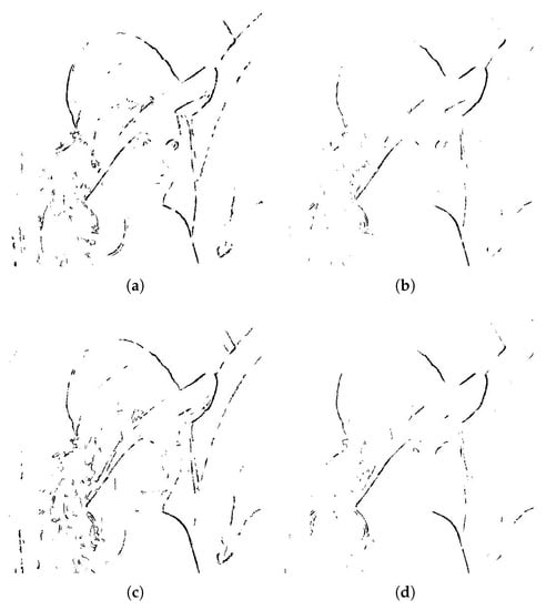
Figure 2.
ACO based complex region detected using. (a) Flat function, (b) Gaussian function, (c) Sine function, and (d) Wave function.
Figure 2, shows that complex region detected with the ACO implemented using Flat function, given in Equation (5), is more prominent than the other functions, followed by Sine function, given in Equation (7). The Gaussian and Wave functions, given in Equations (6) and (8) respectively, results in less dense complex region. Therefore, the proposed technique using Flat and Sine functions can hide more data as compared to that implemented with Gaussian and Wave functions. Hence, large hiding capacity can be achieved with Flat and Sine functions.
However, we will restrict our experiment to Flat and Gaussian functions because the results of the Sine and Wave functions are analogous to Flat and Gaussian functions, respectively. The detected complex region in Figure 2 are used to hide secret information in the cover image in Figure 1. Experiments are performed by dividing complex region pixels of the cover image in different numbers of sectors . The sectors are assigned number bits using increasing distance increasing bits algorithm. For example, the pixels are divided into seven sectors, i.e., , , , , , and . Where is the nearest set of pixels to the reference pixel, and is the farthest set of pixels. According to the increasing distance increasing bits algorithm, the number of bits to be hidden in the pixels of a sector is assigned to each sector. Hence, the sectors , , , , , and are assigned with 1, 2, 3, 4, 5, 6 and 7 number of bits , respectively. This set is used for hiding secret information in the cover image using all the four complex regions shown in Figure 2. The experiments are repeated for the number of sectors equal to 6, 5, and 4 using the range of bits 1–6 bits, 1–5 bits, and 1–4 bits respectively. Experiments are also performed by dividing the complex region pixels in 6, 5, 4, 3 and 2 number of sectors and using the range of bits equal to 2–7 bits, 3–7 bits, 4–7 bits, 5–7 bits and 6–7 bits, respectively. Here, it is important to note that in each experiment, the number of bits hidden per pixel increases with the increase in the distance of the pixels of a sector from the reference pixels. The same experimental is used for all hiding secret information in the cover image using the complex region detected with Flat and Gaussian functions.
Firstly, the experiments are performed using the complex region detected with Flat function. The complex region is used to hide secret information in the cover image. The experiment is repeated for all the previous setup. For each combination of the number of bits, stego image is obtained, and the , , and are computed.
The qualitative results in terms of stego images are obtained for different LSBs combinations, i.e., 1–7 bits, 1–6 bits, 1–5 bits, and 1–4 bits, using the Flat function. The resulting images are shown in Figure 3. Similarly, the stego images obtained with the other bits combinations, i.e., 2–7 bits, 3–7 bits, 4–7 bits, 5–7 bits, and 6–7 bits and the resulting images are shown in Figure 4.
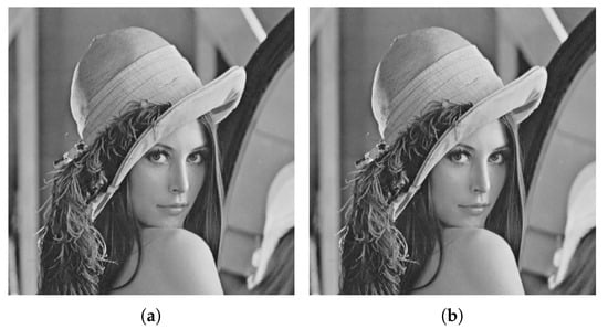
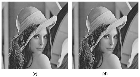
Figure 3.
Stego images using Flat function with (a) and 1–7 bits, (b) and 1–6 bits, (c) and 1–5 bits, and (d) and 1–4 bits.
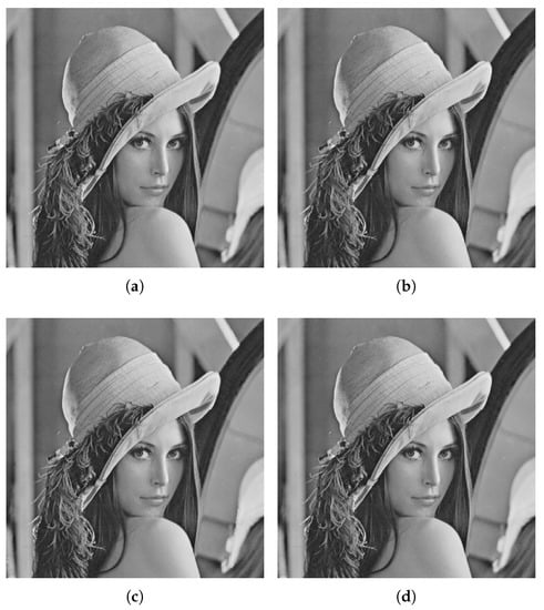
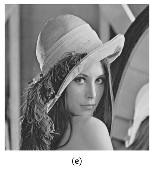
Figure 4.
Stego images using Flat function with (a) and 2–7 bits, (b) and 3–7 bits, (c) and 4–7 bits, (d) and 5–7 bits, and (e) and 6–7 bits.
The experimental results show that the proposed technique, using Flat function, generates high-quality stego images with all the different combinations of bits, i.e., 1–7 bits, 1–6 bits, 1–5 bits and 1–4 bits. The hidden information does not create any visually significant distortion. Similarly, the other combinations of bits, i.e., 2–7 bits, 3–7 bits, 4–7 bits, 5–7 bits, and 6–7 bits, also result in good quality stego images and the hidden information using these combinations do not attract HVS.
The quantitative results obtained with the different combinations of bits, in terms of , , , and , using Flat function are listed in Table 1. The results show that as the number range is reduced from 1–7 to , the maximum number of bits hidden pixels reduces from 7 to 4 and results in a reduction in hiding capacity, i.e., from to . However, the decrease in the range of bits also results in a decrease of and a decrease of and . The reduction in the quality factors is due to the fact that as the range of bits decreases, the number of sectors also decreases. However, the and show that quality of the stego image for all the different combination is quite high and the remains higher than the threshold of 30 dB.

Table 1.
Results for different combinations of LSBs with Flat function.
On the other side, when the range of bits is reduced from 1–7 to 6–7, the average number bits per sector are increased and hence results in an increase in . The hiding improves gradually from to . The other quality measuring parameters remains high. The all the stego images have a higher than the threshold value of 30 dB. Hence, the proposed technique with Flat function efficiently hide secret messages in cover images and keep the existence of the hidden information undetectable.
After the complex region detected with Flat function, the same experiments are repeated using the complex region detected with Gaussian function. The same cover image in Figure 1 is used in the experimentation.
Various combinations of bits are used for information hiding, i.e., 1–7 bits, 1–6 bits, 1–5 bits, 1–4 bits, 2–7 bits, 3–7 bits, 4–7 bits, 5–7 bits and 6–7 bits, and stego images are obtained. The qualitative stego images obtained with LSBs combinations 1–7 bits, 1–6 bits, 1–5 bits, and 1–4 bits, using Gaussian functions, are shown in Figure 5. While stego images obtained with bits combinations 2–7 bits, 3–7 bits, 4–7 bits, 5–7 bits, and 6–7 bits are shown in Figure 6.
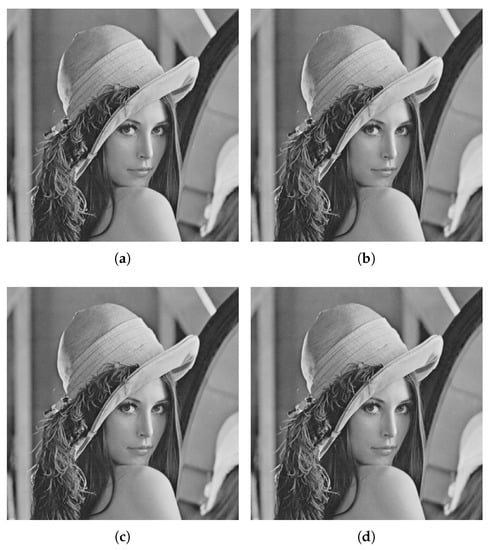
Figure 5.
Stego images using Gaussian function with (a) and 1–7 bits, (b) and 1–6 bits, (c) and 1–5 bits, and (d) and 1–4 bits
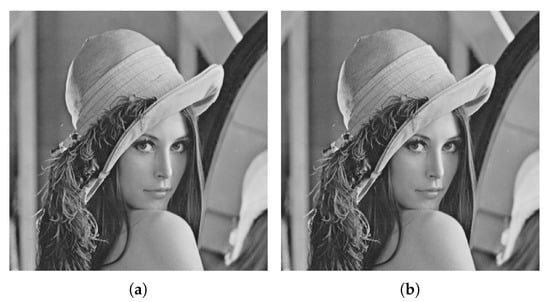
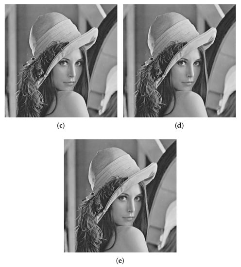
Figure 6.
Stego images using Gaussian function with (a) and 2–7 bits, (b) and 3–7 bits, (c) and 4–7 bits, (d) and 5–7 bits, and (e) and 6–7 bits.
The resulting stego images show that the proposed technique, using Gaussian function, do not add any visually significant distortion and result in high-quality stego images. Similarly, the stego images in Figure 6 obtained using 2–7 bits, 3–7 bits, 4–7 bits, 5–7 bits, and 6–7 bits, have good quality. Hence, the information hidden in the complex region using the proposed technique with the Gaussian function is very efficient and gives good results for different combinations of bits and a number of sectors.
The , , , and , computed after hiding information in the complex region of the cover image, detected with Gaussian function, for the different number of sectors and different combinations of bits are listed in Table 2. The results show that hiding capacity decreases from 1–7 bits to 1–4 bits. This is because of the fact that is moving from 1–7 bits to 1–4 bits; the maximum number of bits hidden in a pixel reduces from 7 to 4. The 1–7 bits combination results in a hiding capacity of while, 1–4 bits combination results in of . However, on the other hand, the performance of the proposed technique in terms of quality measure parameters, i.e., , , and , also decreases. The change of combination of bits from 1–7 bits to 1–4 bits results in an increase in and a decrease in , while the remains almost constant. The combination of 1–7 bits results in , and equal to , and , respectively. While, the 1–4 bits combination results in , and equal to , and , respectively. The quantitative results show that the quality of the stego images for all the different combinations is high, and the remains higher than the threshold of 30 dB.

Table 2.
Results for different combinations of LSBs with Gaussian function.
The results obtained for the combinations of bits, i.e., 1–7, 2–7, 3–7, 4–7, 5–7 and 6–7, show that as the range of bits reduces the increases. This is due to the increases in the average number of bits hidden per sectors. The increases from to . While the quality measuring parameters are affected, and an increase in occurs. The increase in results in a decrease in . However, the still remains higher than the threshold values of 30 dB for the different combinations. Similarly, the technique also results in high values for the different combinations of bits. The qualitative and quantitative results show that the proposed technique with the Gaussian function can efficiently hide secret messages in cover images and keep the existence of the hidden information undetectable.
The experimental results show that the , , , and vary with change in the number of sectors and the combination bits used. Moreover, these parameters also vary with the change in the function used for complex region detection. However, by closely observing the experimental results obtained for each of the functions, it can be observed that the performance of the proposed technique decreases in terms of and the quality when the bits combination varies from 1–7 bits to 1–4 bits. This shows that a 1–7 bits combination is a better choice to be used for data hiding. On the other hand, the of the proposed technique increase as we move from 1–7 bits combination to 6–7 bits combination. However, the performance in terms of the quality measuring parameter decreases. Here it is important to mention that the quality of the stego images remains better, and remains above the threshold value of 30 dB. Therefore, any of these combinations of bits can be used for hiding secret information in cover images. However, the 1–7 bits combination is preferred due to high variability and hence have enhanced security. Therefore, I will use the 1–7 bits combination for data hiding with in the rest of the experiments.
The previous experiments are performed using only one cover image, i.e., Lena. However, the experimentation on one cover image is not enough to prove the effectiveness of a data hiding technique. Therefore, it this section, the proposed technique is tested on different cover images, including Cameraman, House, Jelly Beans, Lena, Mandrill, Pepper, Tiffany, and Tree, shown in Figure 7a–f. The cover images are of different sizes and are converted to grayscale images. The cover images are processed for edges detection using ACO based complex region detection technique using Flat and Gaussian functions, given in Equations (5) and (6). To detect the complex regions the parameters of , , , and are set to 10, 1, , and , respectively, for ACO to operate. The determination of the above parameters is critical to the performance of the proposed approach. Therefore, we have used the values reported in [23] for the ACO to operate. After complex region detection, secret information is hidden in each cover image using a 1–7 bits combination. The experiments are repeated for all the complex regions detected using different functions each.
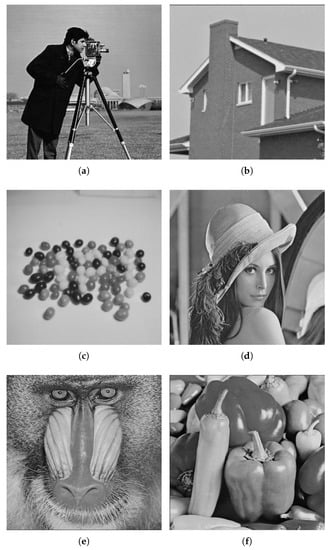
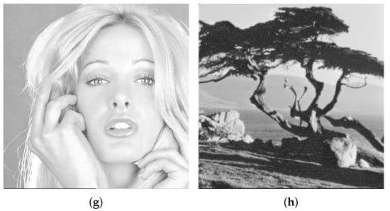
Figure 7.
Cover images. (a) Cameraman, (b) House, (c) Jelly Beans, (d) Lena, (e) Mandrill, (f) Pepper, (g) Tiffany, and (h) Tree.
As the proposed technique, four different functions to detect complex region in a cover image and hide secret information using the suggested data hiding technique. However, similar to the previous experiments, the experiments are performed using Flat and Gaussian functions only, using each of the cover images one by one. The information are hidden in the complex region of each cover image using increasing distance increasing bits substitution algorithm with and bits combination of 1–7 bits.
Firstly, the experiments are performed, using the complex region detected with Flat function, as expressed in Equation (5). The resulting complex regions are shown in Figure 8.
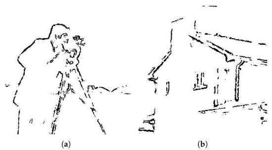
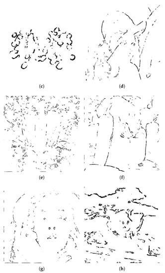
Figure 8.
Complex region detected using Flat function. (a) Cameraman, (b) House, (c) Jelly Beans, (d) Lena, (e) Mandrill, (f) Pepper, (g) Tiffany, and (h) Tree.
The complex region of different cover images, shown in Figure 8, are used for data hiding in the complex region of the corresponding cover images. The resulting stego images obtained with a 1–7 bits combination are shown in Figure 9. The results show that the proposed technique generates high-quality images after hiding information in different cover images. The hidden information does not add any significant distortion in the stego images. Hence, the presence of hidden information remains undetectable.
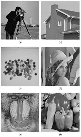
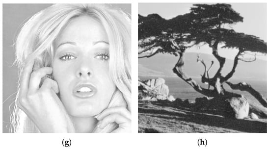
Figure 9.
Stego images using Flat function and 1–7 bits combination. (a) Cameraman, (b) House, (c) Jellybeans, (d) Lena, (e) Mandrill, (f) Pepper, (g) Tiffany and (h) Tree.
The qualitative results, listed in Table 3 shows that a minimum of is obtained for Cameraman cover image, and a maximum of is obtained for Mandrill cover image. The varies from image to image depending on the density of the complex region. The image has a denser complex region, i.e., having a large number of pixels in a complex region, demonstrates large relative to less dense ones. This is the main reason that Mandrill demonstrates a large than the Cameraman cover image. The results further show that the quality of stego images for all the cover image is significantly high and have higher than the threshold of 30 dB. A minimum of and of 52.7071 dB and , respectively, have been obtained in the experiments using the cover images in Figure 8.

Table 3.
Results for different cover images using Flat function.
The cover images in Figure 8 are processed using the ACO based edge detection using Gaussian function, expressed in Equation (6). The resulting complex regions are displayed in Figure 10. After this the complex region detection, the cover images are subjected to information hiding using the binary patterns of the detected complex region. The proposed technique is used to get stego images with bits combination of 1–7 bits. The resulting stego images are shown in Figure 11. The results show that the proposed technique also generates high-quality images with the Gaussian function. The quality of all the stego images is high enough, and the hidden information remains innocent and undetectable to HVS.
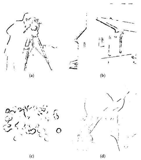
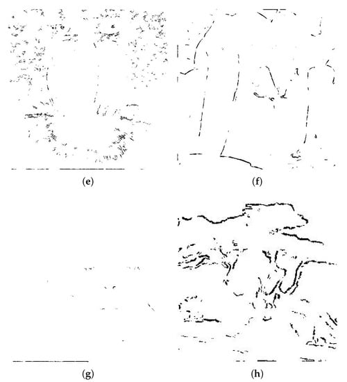
Figure 10.
Complex region detected using Gaussian function. (a) Cameraman, (b) House, (c) Jelly Beans, (d) Lena, (e) Mandrill, (f) Pepper, (g) Tiffany, and (h) Tree.
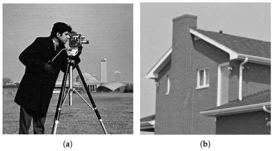
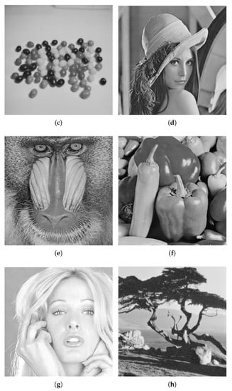
Figure 11.
Stego images using Gaussian function and 1–7 bits combination. (a) Cameraman, (b) House, (c) Jellybeans, (d) Lena, (e) Mandrill, (f) Pepper, (g) Tiffany and (h) Tree.
The qualitative results obtained with the Gaussian function are in Table 4. The results show that a minimum of is obtained for House cover image. It can be seen in Table 3 and Table 4 that proposed technique achieves high with Flat function as compared to Gaussian function, for the same cover images. The reason behind the reduction in is that Flat results in a denser complex region than that of Gaussian function. Similar to the results obtained with Flat function, the proposed technique generates a high quality of stego images with Gaussian function as well. The Gaussian function gives even better results in terms of and . A minimum of 53.9474 dB is obtained for Cameraman cover image, which is much higher than the 30 dB.

Table 4.
Results for different cover images using Gaussian function.
4. Comparison
As discussed in the previous sections, The hiding technique is used for information hiding in the complex region, and the complex region can be detected using any of the four different functions, i.e., Flat, Gaussian, Sine, and Wave function. The technique creates a quality stego image for all the functions, as discussed in Section 3. Besides the better performance of the proposed algorithm on different cover images, it is vital to analyze and compare the performance of the proposed data hiding technique with other techniques. Therefore, after extensive experimentation and results analysis, the comparison of the proposed technique with different data hiding techniques is presented in this section.
The proposed technique is compared with well-known data hiding techniques of Honsinger et al. [4], Macq and Dewey [35], Fridrich et al. [3], Lin and Li [36], Jaiswal et al. [37], Goljan et al. [38], Vleeschouwer et al. [39], Khan et al. [16] and Khan and Tiziano [30]. The same cover images of Lena and Mandrill are used for experiments to make a comprehensive comparison. The stego images are obtained for each cover image using each of the mentioned techniques. The comparison is made based on , , and . The values of these parameters are computed for each of the algorithms using each of the cover images. The results obtained are listed in Table 5. As the proposed technique is can be implemented using four different functions, therefore, the results generated each of the functions, with a 1–7 bits combination, is presented for comparison purposes.

Table 5.
The Comparison of proposed technique with other data hiding techniques.
The results presented in Table 5, show that the proposed technique with all the different functions has a higher than all the algorithms presented in the comparison section. The proposed method has achieved a of and with Flat function using Lena and Mandrill images as cover media, respectively, which are higher than the of all other techniques on the same cover images. The obtained by the proposed technique with the different functions is also better than the of all the other methods, using both the cover images, i.e., Lena and Mandrill. The highest of 61.4498 dB is demonstrated by the proposed technique using Lena as cover.
Similarly, looking at the result obtained using the Mandrill image, the proposed technique gives the highest of 57.744 dB with Gaussian function. The proposed technique also proves its superiority in terms of computed. The results show that the proposed technique has the better or comparable quality of stego images in terms of .
5. Conclusions
The proposed technique hides secret information in the complex region of a cover image in an asymmetric manner. It has a different possible implementation in terms of the function used for complex region detection using the ACO algorithm. The asymmetry in hiding information is ensured using increasing distance increasing bits algorithm. The variety of functions and the asymmetric hiding of information enhanced the security of the hidden information. Along with a high level of security, the proposed technique has high data hiding capacity, , and as compared to other data hiding techniques. The results show that the proposed technique has a variable data hiding capacity, depending on the bits combination and function used for hiding information. The resulting of the proposed method is always higher than the threshold value of 30 dB. The method has higher than for different cover images. The overall results show the hidden information does not create any visually significant distortion in the stego images and make the presence of hidden information undetectable. Hence, the proposed framework is an efficient way of information hiding using images as cover media. However, the proposed technique can generate worst results if 8 bits are hidden in each pixel of the complex region. However, in such a scenario, the technique will no more remain variable data hiding. Instead, it will become fixed data hiding. In nutshell, the proposed technique is a highly efficient data hiding technique, creating high-quality stego images without creating any visually significant distortion. Our proposed method has better or comparable performance than previous data hiding techniques.
Author Contributions
All authors equally contributed in this research work. All authors have read and agreed to the published version of the manuscript.
Funding
This research received no external funding.
Conflicts of Interest
The authors declare no conflict of interest.
References
- Johnson, N.; Jajodia, S. Exploring steganography: Seeing the unseen. Computer 1998, 31, 26–34. [Google Scholar] [CrossRef]
- Swanson, M.; Kobayashi, M.; Tewfik, A. Multimedia data-embedding and watermarking technologies. Proc. IEEE 1998, 86, 1064–1087. [Google Scholar] [CrossRef]
- Fridrich, J.; Goljan, M.; Du, R. Invertible authentication. In Security and Watermarking of Multimedia Contents III; International Society for Optics and Photonics: Bellingham, WA, USA, 2001; Volume 4314, pp. 197–208. [Google Scholar]
- Honsinger, C.; Jones, P.; Rabbani, M.; Stoffel, J. Lossless Recovery of an Original Image Containing Embedded Data. U.S. Patent 6,278,791, 21 August 2001. [Google Scholar]
- Kaur, D.; Verma, H.K.; Singh, R.K. Image Steganography: Hiding Secrets in Random LSB Pixels; Springer: Berlin/Heidelberg, Germany, 2020; pp. 331–341. [Google Scholar]
- Khan, S.; Yousaf, M.H.; Akram, J. Implementation of Variable Least Significant Bits Stegnography using DDDB Algorithm. Int. J. Comput. Sci. Issues 2011, 8, 292–296. [Google Scholar]
- Irfan, M.; Ahmad, N.; Khan, S. Analysis of Varying Least Significant Bits DCT and Spatial Domain Stegnography. Sindh Univ. Res. J. 2014, 46, 301–306. [Google Scholar]
- Khan, S.; Ahmad, N.; Wahid, M. Varying index varying bits substitution algorithm for the implementation of VLSB steganography. J. Chin. Inst. Eng. 2016, 39, 101–109. [Google Scholar] [CrossRef]
- Lin, J.; Lin, C.C.; Chang, C.C. Reversible Steganographic Scheme for AMBTC-Compressed Image Based on (7, 4) Hamming Code. Symmetry 2019, 11, 1236. [Google Scholar]
- Hong, W.; Ma, Y.B.; Wu, H.C.; Chen, T.S. An efficient reversible data hiding method for AMBTC compressed images. Multimed. Tools Appl. 2017, 76, 5441–5460. [Google Scholar] [CrossRef]
- Shelupanov, A.; Evsyutin, O.; Konev, A.; Kostyuchenko, E.; Kruchinin, D.; Nikiforov, D. Information Security Methods—Modern Research Directions. Symmetry 2019, 11, 150. [Google Scholar] [CrossRef]
- Khan, S.; Ismail, M.; Khan, T.; Ahmad, N. Enhanced stego block chaining (ESBC) for low bandwidth channels. Secur. Commun. Netw. 2016, 9, 6239–6247. [Google Scholar] [CrossRef]
- Khan, S.; Irfan, M.A.; Arif, A.; Ali, A.; Memon, Z.A.; Khaliq, A. Reversible-Enhanced Stego Block Chaining Image Steganography: A Highly Efficient Data Hiding Technique. Can. J. Electr. Comput. Eng. 2020, 43, 66–72. [Google Scholar] [CrossRef]
- Zakaria, A.A.; Hussain, M.; Wahab, A.W.A.; Idris, M.Y.I.; Abdullah, N.A.; Jung, K.H. High-capacity image steganography with minimum modified bits based on data mapping and LSB substitution. Appl. Sci. 2018, 8, 2199. [Google Scholar] [CrossRef]
- Sadat, E.S.; Faez, K.; Saffari Pour, M. Entropy-based video steganalysis of motion vectors. Entropy 2018, 20, 244. [Google Scholar] [CrossRef]
- Khan, S.; Ahmad, N.; Ismail, M.; Minallah, N.; Khan, T. A secure true edge based 4 least significant bits steganography. In Proceedings of the 2015 International Conference on Emerging Technologies (ICET), Peshawar, Pakistan, 19–20 December 2015; pp. 1–4. [Google Scholar]
- Rong, W.; Li, Z.; Zhang, W.; Sun, L. An improved CANNY edge detection algorithm. In Proceedings of the 2014 IEEE International Conference on Mechatronics and Automation, Tianjin, China, 6 August 2014; pp. 577–582. [Google Scholar]
- Bourennane, E.; Gouton, P.; Paindavoine, M.; Truchetet, F. Generalization of Canny–Deriche filter for detection of noisy exponential edge. Signal Process. 2002, 82, 1317–1328. [Google Scholar] [CrossRef]
- Khan, S.; Bianchi, T. Fast Image Clustering Based on Camera Fingerprint Ordering. In Proceedings of the 2019 IEEE International Conference on Multimedia and Expo (ICME), Shanghai, China, 12 July 2019; pp. 766–771. [Google Scholar]
- Gupta, S.; Mazumdar, S.G. Sobel edge detection algorithm. Int. J. Comput. Sci. Manag. Res. 2013, 2, 1578–1583. [Google Scholar]
- Yang, L.; Wu, X.; Zhao, D.; Li, H.; Zhai, J. An improved Prewitt algorithm for edge detection based on noised image. In Proceedings of the 2011 4th International Congress on Image and Signal Processing, Shanghai, China, 17 October 2011; Volume 3, pp. 1197–1200. [Google Scholar]
- Maini, R.; Aggarwal, H. Study and comparison of various image edge detection techniques. Int. J. Image Process. 2009, 3, 1–11. [Google Scholar]
- Tian, J.; Yu, W.; Xie, S. An ant colony optimization algorithm for image edge detection. In Proceedings of the 2008 IEEE Congress on Evolutionary Computation (IEEE World Congress on Computational Intelligence), Hong Kong, China, 1 June 2008; pp. 751–756. [Google Scholar]
- Guan, N.; Tao, D.; Luo, Z.; Yuan, B. NeNMF: An optimal gradient method for nonnegative matrix factorization. IEEE Trans. Signal Process. 2012, 60, 2882–2898. [Google Scholar] [CrossRef]
- Hong, W.; Chen, T. A novel data embedding method using adaptive pixel pair matching. IEEE Trans. Inf. Forensics Secur. 2011, 7, 176–184. [Google Scholar] [CrossRef]
- Hsu, C.; Tu, S. Probability-based tampering detection scheme for digital images. Opt. Commun. 2010, 283, 1737–1743. [Google Scholar] [CrossRef]
- Subhedar, M.; Mankar, V. Current status and key issues in image steganography: A survey. Comput. Sci. Rev. 2014, 13, 95–113. [Google Scholar] [CrossRef]
- Hong, W.; Chen, T.; Shiu, C. Reversible data hiding for high quality images using modification of prediction errors. J. Syst. Softw. 2009, 82, 1833–1842. [Google Scholar] [CrossRef]
- Jung, K.; Yoo, K. Data hiding using edge detector for scalable images. Multimed. Tools Appl. 2014, 71, 1455–1468. [Google Scholar] [CrossRef]
- Khan, S.; Bianchi, T. Ant colony optimization (aco) based data hiding in image complex region. Int. J. Electr. Comput. Eng. 2018, 8, 379–389. [Google Scholar] [CrossRef]
- Dorigo, M.; Thomas, S. Ant Colony Optimization; MIT Press: Cambridge, UK, 2004. [Google Scholar]
- Duan, H. Ant Colony Algorithms: Theory and Applications; Chinese Science: Beijing, China, 2005. [Google Scholar]
- Wang, Z.; Bovik, A. A universal image quality index. IEEE Signal Process. Lett. 2002, 9, 81–84. [Google Scholar] [CrossRef]
- Wang, Z.; Bovik, A.; Sheikh, H.; Simoncelli, E. Image quality assessment: From error visibility to structural similarity. IEEE Trans. Image Process. 2004, 13, 600–612. [Google Scholar] [CrossRef]
- Macq, B.; Dewey, F. Trusted headers for medical images. In Proceedings of the DFG VIII-D II Watermarking Workshop, Erlangen, Germany, 3 October 1999; Volume 10. [Google Scholar]
- Lin, Y.C.; Li, T.S. Reversible Image Data Hiding Using Quad-tree Segmentation and Histogram Shifting. J. Multimed. 2011, 6, 349–358. [Google Scholar] [CrossRef]
- Jaiswal, S.P.; Au, O.; Jakhetiya, V.; Guo, A.Y.; Tiwari, A.K. Adaptive predictor structure based interpolation for reversible data hiding. In Proceedings of the International Workshop on Digital Watermarking, Taipei, Taiwan, 1 October 2014; pp. 276–288. [Google Scholar]
- Goljan, M.; Fridrich, J.; Du, R. Distortion-free data embedding for images. In Proceedings of the International Workshop on Information Hiding, Pittsburgh, PA, USA, 27 April 2001; pp. 27–41. [Google Scholar]
- Vleeschouwer, C.; Delaigle, J.; Macq, B. Circular interpretation of histogram for reversible watermarking. In Proceedings of the 2001 IEEE Fourth Workshop on Multimedia Signal Processing, Cannes, France, 5 October 2001; pp. 345–350. [Google Scholar]
© 2020 by the authors. Licensee MDPI, Basel, Switzerland. This article is an open access article distributed under the terms and conditions of the Creative Commons Attribution (CC BY) license (http://creativecommons.org/licenses/by/4.0/).