Article

A Vertex-Aligned Model for Packing 4-Hexagonal Clusters in a Regular Hexagonal Container

1
Faculty of Electrical Engineering, Mechanical Engineering and Naval Architecture (FESB), University of Split, 21000 Split, Croatia
2
University Department of Professional Studies, University of Split, 21000 Split, Croatia
3
Fermi National Accelerator Laboratory (Fermilab), Batavia, IL 60510-5011, USA
*
Author to whom correspondence should be addressed.
Symmetry 2020, 12(5), 700; https://doi.org/10.3390/sym12050700
Submission received: 30 January 2020 / Revised: 20 February 2020 / Accepted: 28 February 2020 / Published: 1 May 2020

Abstract

:
This paper deals with a problem the packing polyhex clusters in a regular hexagonal container. It is a common problem in many applications with various cluster shapes used, but symmetric polyhex is the most useful in engineering due to its geometrical properties. Hence, we concentrate on mathematical modeling in such an application, where using the “bee” tetrahex is chosen for the new Compact Muon Solenoid (CMS) design upgrade, which is one of four detectors used in Large Hadron Collider (LHC) experiment at European Laboratory for Particle Physics (CERN). We start from the existing hexagonal containers with hexagonal cells packed inside, and uniform clustering applied. We compare the center-aligned (CA) and vertex-aligned (VA) models, analyzing cluster rotations providing the increased packing efficiency. We formally describe the geometrical properties of clustering approaches and show that cluster sharing is inevitable at the container border with uniform clustering. In addition, we propose a new vertex-aligned model decreasing the number of shared clusters in the uniform scenario, but with a smaller number of clusters contained inside the container. Also, we describe a non-uniform tetrahex cluster packing scheme in the proposed container model. With the proposed cluster packing solution, it is accomplished that all clusters are contained inside the container region. Since cluster-sharing is completely avoided at the container border, the maximal packing efficiency is obtained compared to the existing models.

1. Introduction

A problem of packing objects in the container of a given shape is common in many applications such as computer science, manufacturing, industrial engineering, and production [1]. Various container types are studied, such as rectangular [2,3], circular [4], or polygonal geometrical shapes [5,6]. Also, problems of embedding many different items are investigated, where the inner components can be regular circular-like [7] or irregular objects [8,9]. Even though most of the research supports the approximation of different container shapes with the minor change of the cost function, special attention is devoted to packing polygons into the circular or polygonal region of interest (ROI) [2,10]. It is crucial in applications such as sensor manufacturing when polygonal sensors are cut out from the circular wafer [11]. In some cases, inner objects are not independent, in sense, they have to be grouped in a number of clusters before being embedded inside the container. For example, when polygonal clusters are formed inside the polygonal area covered with wireless sensor devices to obtain increased energy efficiency [12].
Clusters can be packed in the container with various objectives. For example, a cluster layout can be optimized to increase packing density with maximal distance among clusters [1], or the aim could be to minimize the size of the container still containing the cluster collection [9]. Our work is similar to studies that intend to maximize the packed area by embedding as many clusters as possible in the container area [2,3,10]. Litvinchev et al. [2] studied this problem with the aim of packing a certain number of circular-like objects such as circles, ellipses, rhombuses, and polygons of known size into a rectangular shape. Authors approximate containers by regular grids used to simplify the packing problem. This strategy was introduced earlier by Stoyan and Yaskov [13], who applied a hexagonal lattice for packing circles by assigning their centers to the nodes of the grid. Similarly, Galiev and Lisafina [10,14], developed their specific grid-based models for packing a maximal number of equal and unequal regular objects inside the square or rectangular container. Toledo et al. [15] showed that using a square grid in the packing problem can simplify even the non-trivial handling of the geometry required in case of irregular objects. However, we are interested only in regular packing, which involves standard shapes of objects and containers, unlike the ones where the distance of objects to the container centroid is not Euclidean [16,17]. In the work of Torres-Escobar et al. [3], the grid is discretized with a set of points in which circular objects can be assigned such that there are no overlaps and to maximize the space occupied. The optimal packing of discs in regular rings of uniform circles with minimal distance is examined in [18]. There are additional researches that utilize the regular grid of points, but with another packing objective, i.e., to place the fixed-size objects in a container of minimal size and area [6,19].
In this paper, we concentrate on the goal to pack as many items as possible in the regular hexagonal container and to determine the maximal number of inner packed clusters. The issue of shared clusters is only tackled in [13], where authors refer to these as prohibited areas which cause the modification of the hexagonal lattice packing. We believe that these shared or partial objects should be discussed, as they cannot be considered the inner packed items. They are unpacked, but they take place in the container and prevent us from putting the whole cluster inside the container border. They also cause increased void areas that we want to minimize and maximize the occupied space.
Unlike previous studies where not necessarily the same size of all packed objects is considered, we focus on the more uniform approach, considering all items to be the same in size and type. Also, the orthogonally oriented objects are mostly used in former research where objects are identical [2,7,13,14,16]. If the non-identical items in size and type are given, they are usually free of any orientation restrictions. Authors in [1,9], for instance, allow free rotations of the polygons and use separation lines with direct trigonometry in Cartesian coordinates to ensure non-overlapping, while Lopez and Beasley [17] separate two packing cases with the rotation of objects allowed or not. We consider the packed items to all have the same orientation but in another context. Naturally, as pointed out in [4], given the grid approximation of the container, this approach can only handle the packing of uniformly sized and uniformly oriented items inside a container. Since 4-hexagonal clusters or polyhex structures are formed by merging hexagonal cells together [20,21], we can examine several fixed and uniform cluster rotations and obtain the optimal packing solution.
We adopt the idea where the nodes of the regular hexagonal grid are considered as positions for assigning centers of the hexagonal cells. Similar to Lintzmayer [19], we utilize the hexagon tessellation method to embed hexagonal cells inside hexagonal ROI. Hexagons are chosen due to their advantages and nice properties in covering the entire plane [22,23]. We group the inner hexagonal cells into clusters of four or tetrahexes, to obtain the desired packing result of the polyhex clusters. The process of forming polyhex clusters is given in Figure 1. Since the shape of the cluster depends on the way that the cells are merged [20,21], there are seven possible combinations for clustering four hexagons, forming in total seven different 4-hexagonal clusters.
The research in this paper is application-driven, and a specific engineering application in our focus is the design upgrade of the new Compact Muon Solenoid (CMS), which is one of four detectors used in Large Hadron Collider (LHC) experiment at European Laboratory for Particle Physics (CERN). Namely, the future high granularity calorimeter (HGCAL) of CMS will consist of about 6 million channels, and not all sensor data could be read and stored for further processing. There are 40 million events per second, while only a few hundreds of events per second can currently be recorded offline. CMS uses a trigger system to select the events of interest whose data is stored and analyzed [24]. Also, the bandwidth requirements should be met in order to send the data, so a reduction is applied in several forms. One of the approaches is based on the detector geometry design, where data reduction is performed by using the clustering procedure. Hence, detector hexagonal sensor cells are grouped into larger 4-hexagonal clusters called “trigger cells”. For this purpose, hexagonal sensor modules are produced and used to cover a detector surface, where each of them contains a set of small hexagonal sensor energy readout cells grouped in 4-hexagonal clusters [25,26].
Since clusters or “trigger cells” are formed from hexagonal sensors embedded in the hexagonal HGCAL sensor module, intuitively, clusters should also be packed in the module. Hence, the mathematical problem in the current engineering context is a problem of packing 4-hexagonal (tetrahex) rhomboid clusters in the regular hexagonal module (container). The real applicability of the study is how to solve the packing problem for this specific application. Each container should contain its own clusters or, at least, the number of shared clusters at the container border should be minimized. This is to reduce or possibly to avoid communication between boards that are processing data from each of the neighboring containers separately. Ideally, the cluster plane should remain uniform to keep the simplicity of the nearest neighbor (NN) algorithm [24].
For our research, we select the densest 4-hexagonal clusters that are the most closely packed, so only three out of seven combinations could be considered (Figure 2). Since symmetry in forming “trigger cells” is of great interest for us, we choose clusters with two symmetry axes, approximated by a rhomboid shape. Furthermore, we are interested in clusters that allow period tessellation with two translation symmetries in two non-parallel directions. An additional requirement for cluster selection is the perimeter minimization. According to [27], a polyhex is optimal if it has a minimal perimeter with respect to all polyhexes with the same number of hexagons. The 4-hexagonal cluster named “bee” tetrahex allows periodic tessellation, and it is minimal in perimeter and rhomboid in shape. We find it optimal for our application, and many authors use it due to its broad applicability in engineering based on its geometry and symmetrical structure [21].
To the best of our knowledge, the problem of packing polyhex clusters composed of the hexagonal cells inside a regular hexagonal container is addressed for the first time in this paper. The main contributions are the following: First, the cluster layout for 4-hexagonal clusters packed in the regular hexagonal container is visualized and analyzed. Then, we investigate two different existing layouts: the centroid-aligned (CA) and vertex-aligned (VA) models [12,28]. In CA, the container center overlaps with the center of the central hexagonal cell, while in VA, the container center is at the vertex that belongs to one of the embedded hexagons. Next, mathematical expressions are derived, providing the number of full clusters packed in the container, as well as the number of shared clusters at the container border. Finally, we propose a new VA model (adjusted from [29]) to solve the packing problem such that all hexagonal clusters are contained in the inner part of the container, completely avoiding shared clusters at the container border.
The paper is organized as follows. Section 2 provides the problem formulation and theoretical background on forming hexagonal clusters and their uniform tessellation with various cluster orientations. Next, the research methodology is formulated. Clustering with the existing models from the literature and the proposed geometrical model are presented in Section 3 and Section 4 respectively. Section 5 summarizes the results with the discussion on the efficiency of architectures used for cluster packing and their comparison. Section 6 deals with the limitations of the study. The conclusion is given in Section 7 followed by the references used.

2. Problem Formulation

2.1. Formal Definition of Cluster Packing

A problem of packing polyhex clusters in the hexagonal region can be formally described as follows. First, a plane is hexagonally tessellated by using a regular hexagonal grid. Then, the same plane is covered with another regular hexagonal grid at a larger scale. These hexagons represent the regular hexagonal packing container. The size of hexagons in this new grid is defined by its (double) apothem expressed in the number of smaller hexagons (from the base tessellation).
Finally, the small hexagons are packed in 4-hexagonal clusters, as shown in Figure 3. Clusters are forming a regular cluster grid or cluster plane, and the center of the defined plane must overlap with the center of one of the hexagons contained in 4-hexagonal cluster. Possibly, all clusters must be inside the container such that their packing is efficient.

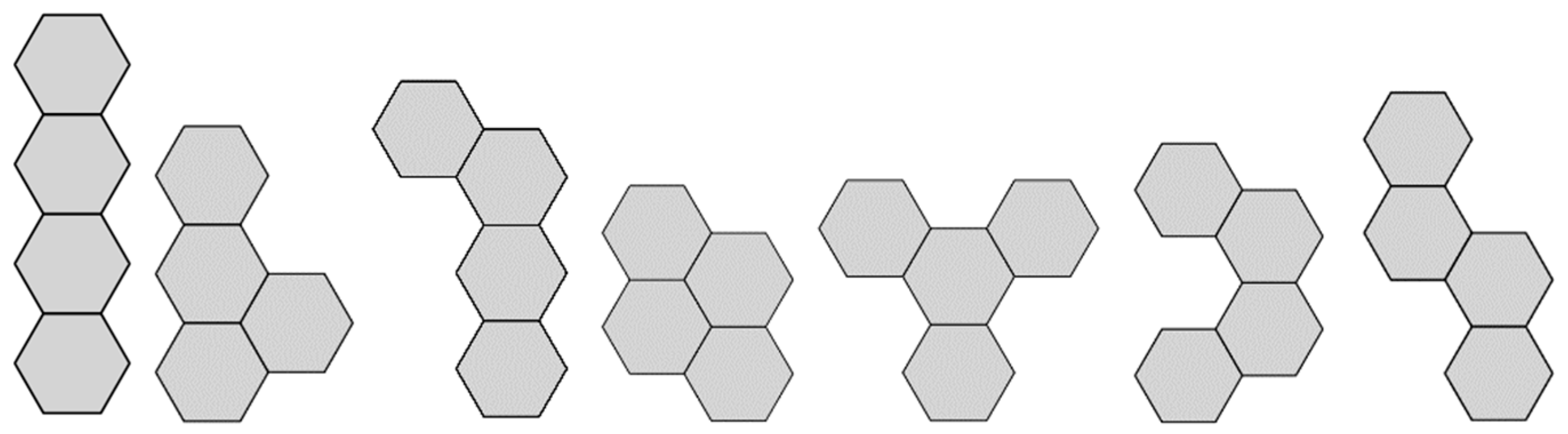
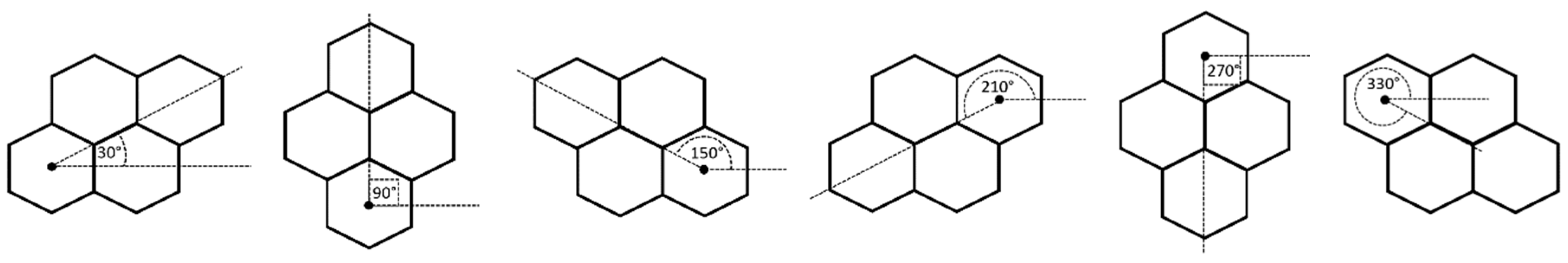
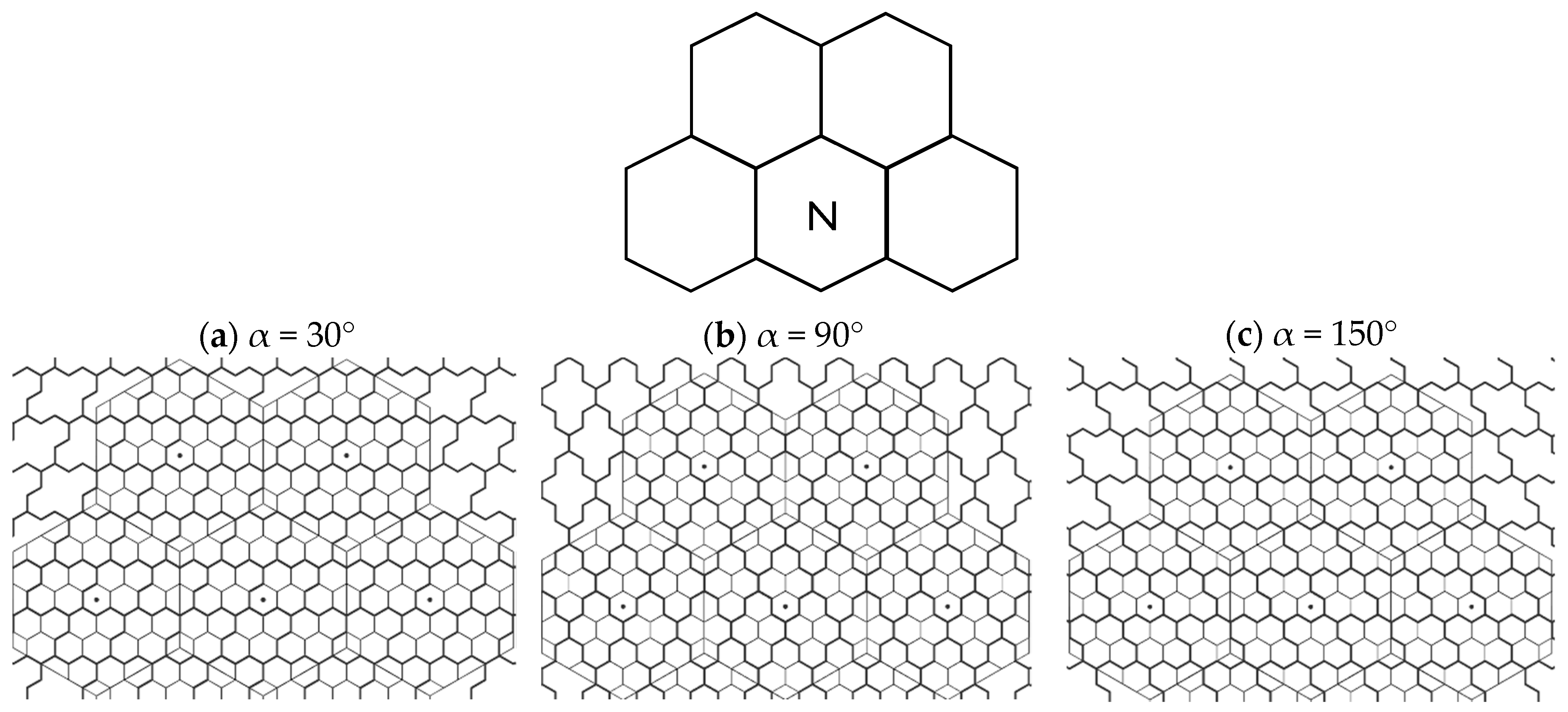
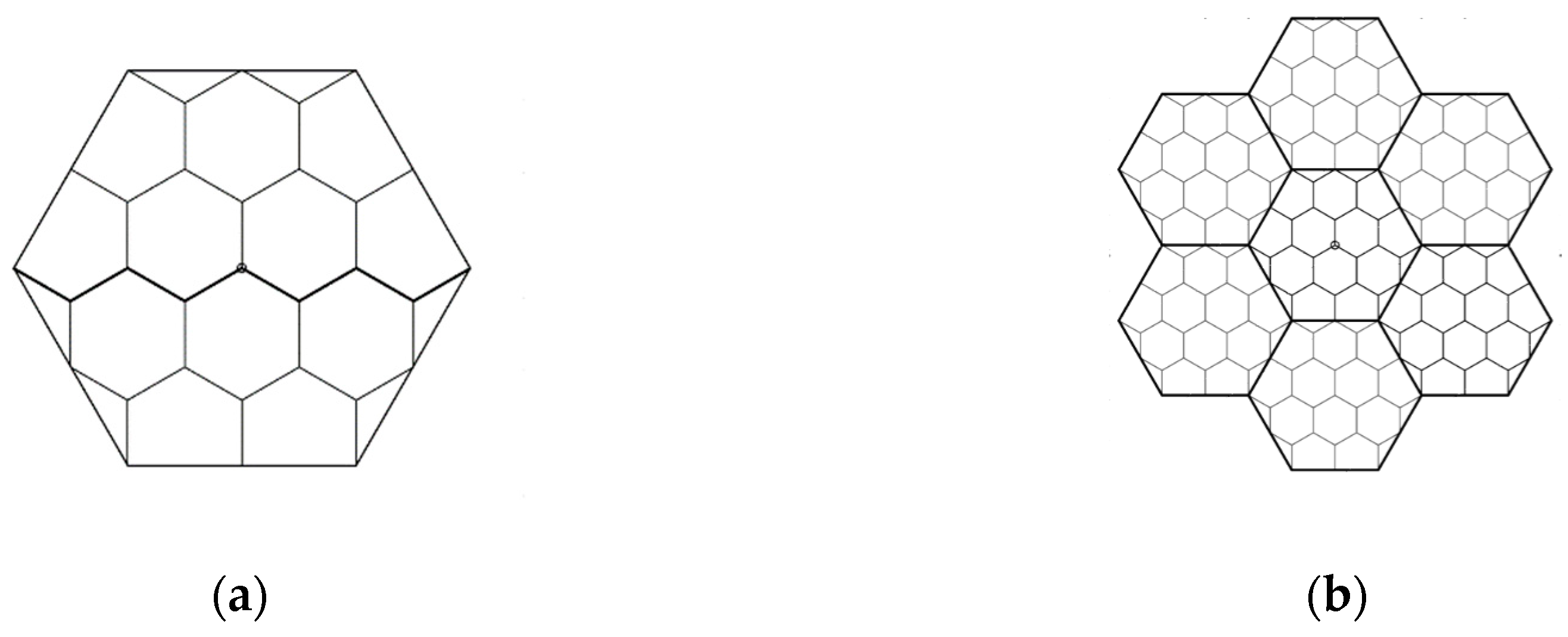
2.2. Cluster Plane Uniformity and Cluster Orientations

We define the cluster plane to be uniform if all clusters obtain the same orientation and size (area). The uniformity of the plane has the nice property that all the distance from the central cluster to all NN clusters is the same as given in Figure 4. With the hexagon of side length a , the center of the central cluster has coordinates S 0 ( 3 a 3 4 , 3 a 4 ) and distance to all NN cluster centers is d = 2 a 3 .
Clusters can have various orientations in the cluster plane, and we examine the possibilities with the rotation angles of step 60° (30°, 90°, 150°, 210°, 270°, 330°). The example in Figure 4 represents the basic 30° angle of the 4-hexagonal cluster, and the remaining orientations are given in Figure 5.

2.3. Research Problems

A problem of forming 4-hexagonal clusters is expressed by the following problem formulations:
  • Problem 1. How to cluster the tessellated plane of hexagonal cells, such that the cluster plane remains uniform?
    Is it possible to enclose all clusters inside a regular hexagonal container by using the existing models from the literature?
    How to calculate the total number of inner clusters inside the container and the total number of shared clusters at the container border?
  • Problem 2. How to derive a model from obtaining a new structure for hexagonal clustering, with clusters entirely embedded inside the container while keeping the cluster plane uniform?
  • Problem 3. What is the efficiency of the proposed geometrical structure compared to the existing models in terms of the total number of packed clusters inside the container?

2.4. Research Context

In order to solve the above-formulated research problems, we concentrate on “bee” tetrahex clusters, having the minimal perimeter and that are rhomboid in shape (Figure 2b). It is assumed in our analysis that clustering starts with the central cluster contained in (0, 0), i.e., that the clustering center overlaps with the center of the container (CA architecture), or with the cell that is closest to the container center (VA architecture). We consider the cluster orientations in the packing procedure, as shown in Figure 5. Our main intention with cluster packing is to keep the cluster plane uniform so that all clusters are the same in area and orientation, and the distance from the central cluster to its NNs its constant.
We apply clustering with existing models from the literature, CA, and VA structures, and we propose a VA model that enables all clusters to be packed in the container, with no partial clusters shared at the border. We calculate the number of different container types provided by each of the architectures when containers with the packed hexagonal clusters are tessellated, where our aim is to have a single container type. Also, our intention is to derive mathematical expressions from calculating the number of full (inner packed) and shared (border) clusters so that we can evaluate that indeed the proposed model is more efficient than the existing ones.

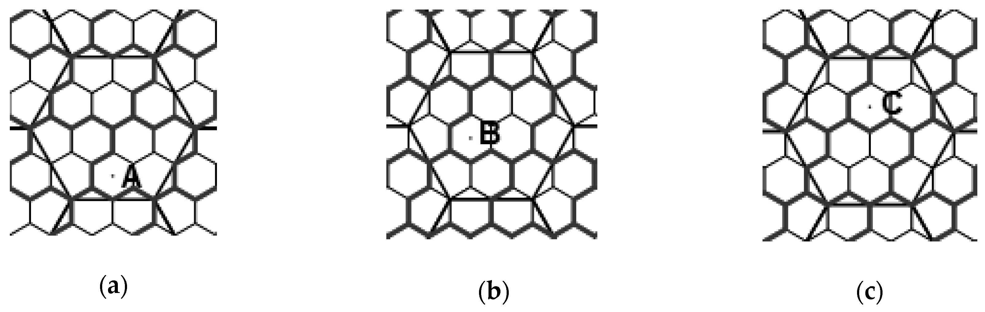
3. Clustering with the Existing Models

The two default variants of multi-resolution hexagonal grids that are often used in the literature are CA model, where small hexagonal cells share their midpoints with the container, and VA model, where the small-cell vertex overlaps with the container centroid [22,28,30].
We apply a hexagonal tessellation approach to solve a packing problem of hexagonal clusters inside a regular hexagonal container. The basis is a regular hexagonal grid whose points are used as centers of the hexagonal cells. This is needed because, for cells to be clustered together, the container must consist of hexagonal cells packed inside (Figure 6). Next, the hexagonal ROIs must be tessellated in the higher-resolution grid, to examine the cluster plane uniformity when hexagonal clusters are formed.
We must choose the center of clustering accordingly. In the case of CA architecture, the center of clustering is straightforward; it is the center of the container (the center of a central hexagon). In VA architecture, the three central hexagons meet in the vertex that is a container center, and one of them needs to be chosen as a clustering center. There are three possibilities (Figure 7): cluster center-left (position A), cluster center-right (position B), and cluster center-down (position C). These three cases can be narrowed to only two since the selection A and B would give the same structure due to the symmetry of the container.
Considering the cluster rotations, in CA architecture, there are three pairs of clusters with different orientations having the same clustering structure. Those cluster orientation pairs are 30° and 210°, 90° and 270°, 150° and 330°. It is straightforward that the second clustering architecture in each pair is obtained by rotation of the first one for 180°. On the other hand, in the VA model, depending on the cluster center position, two different cases can be distinguished. For the cluster center moved down, the orientations 30°, 150°, 210°, and 330° all have the same clustering structure, while for cluster center moved left, the structure for orientations 30°, 90°, 210° and 270° is constant.

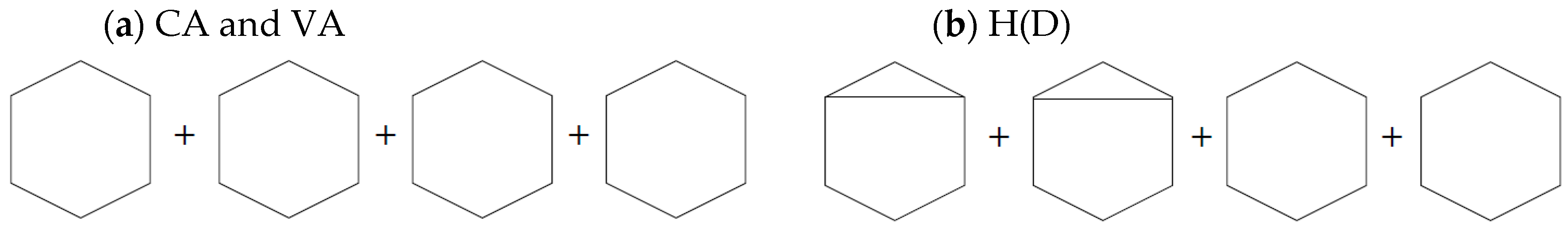
3.1. Centroid-Aligned Architecture

The formal description of the architectures for subdividing a container into a set of smaller hexagons is adopted from [12]. Authors show that the following proposition is valid:
Proposition 1.
For each R / n subdivision in the centroid-aligned container, the number of equal hexagonal cells packed inside is n 2 , where n is the subdivision level (Figure 8).
Proof. 
Refer to [12]. □
We adopt the described CA architecture and form 4-hexagonal clusters inside with using the existing model. We divide the model into two classes, depending on whether the subdivision level n is odd or even. We refer to those classes C A o d d and C A even , respectively. Considering the requirement of the cluster plane uniformity, we examine all the cluster rotations from Figure 5.

3.1.1. Packing 4-Hexagonal Clusters in the Even-Sized CA Container

Let the architecture be C A even , and the container size n = 2 k ,   k N . Let us consider forming 4-hexagonal clusters in the uniform clustering approach and packing the clusters in the regular hexagonal container of even size C A even .
Proposition 2.
If C A e v e n containers are arranged in a tessellated manner, for default orientation (α = 30°) they all have a single clustering structure.
Proof. 
The cluster contains two pairs of hexagons that are arranged in two adjacent rows like it is shown in Figure 9a. When the container size is even number (measured as the number of small hexagons at the double apothem), an integer number of hexagon pairs are positioned between two opposite hexagon sides, which results in the same clustering structure. □
Proposition 3.
No matter of the cluster rotation, there is a single structure of the tessellated C A e v e n containers with the inner packed cluster items, i.e., in Proposition 2, the rotation invariance is valid.
Proof. 
We denote a single container type as container N (Figure 9). According to Proposition 2, C A even containers with 30° orientation will have a single clustering structure. Cluster rotation is available for rotation angles of step 60°. Since a container shape is a regular hexagon, it has rotational symmetry (of order six) with rotation angle 60°. Hence, a container structure remains constant independent of the cluster orientation. □
Clustering results from Figure 10 are summarized in Table 1, providing the number of the packed inner full clusters inside the container and shared clusters at the border, when the default 30° cluster orientation is considered.
Let us derive a single algebraic expression that covers all even container sizes for calculating the number of inner packed cluster items:
N f u l l = ( n / 2 1 ) 2 + n / 6
Authors in [12] prove that as the levels of subdivision n increase, the sub-cells inside (in a one-sixth of a hexagonal container) increase by one for every three levels. This means that there are several sub-clustering architectures inside the larger class C A even . Motivated by that finding, and the clustering visualizations such as the ones in Figure 10, we conclude that the clustering structure depends on whether the container size n is a multiple of three, i.e., we can divide the C A even class in three sub-classes C A even ( r ) based on the remainder of dividing by three (marked with r ), where n = 3 k + r , k N ,   r { 0 ,   1 ,   2 } .
Proposition 4.
There will always be three different clustering structures depending if the even CA container size n is a multiple of 3.
Proof. 
Having a container of size n , the distance from the center of the container to any vertex is equal to n d , where d is the diameter of a small hexagon. Depending on the n value, the path from container center to container vertex is the sequence of vertices A (beginning of the hexagon), B (center of the hexagon), C (end of the hexagon), A, B… like is shown in Figure 11. □
Positions A, B, C alternate sequentially with the increase of container size. Therefore, it is possible to distinguish three different container vertex positions that result in three different clustering architectures depending on the remainder r of dividing n by three. Note that this is valid for any cluster rotation. The recursive formula is valid, covering all CA even containers independent on their type:
N f u l l i + 1 = { N f u l l i + n i , f o r   r = 0 N f u l l i + n i 1 , e l s e
In Equation (2), the index i is an iteration number in the recursion i N 0 , with the initial conditions n 0 = 4 and N f u l l 0 = 1 . Additionally, we derive separate algebraic expressions for calculating the number of inner packed and shared clusters for each architecture type C A even ( r ) .
The number of full clusters N f u l l is:
N f u l l = { ( 3 n 2 10 n + 12 ) / 12 , i f   r = 0 ( 3 n 2 10 n + 4 ) / 12 , i f   r = 1 ( 3 n 2 10 n + 8 ) / 12 , i f   r = 2
The number of shared clusters N s h a r e d is calculated with the following formula:
N s h a r e d = { ( 5 n ) / 3 , i f   r = 0 ( 5 n + 1 ) / 3 , i f   r = 1 ( 5 n 1 ) / 3 , i f   r = 2
Cluster Rotation Invariance: As it can be seen in Figure 9, the number of inner clusters N f u l l and N s h a r e d is constant for all cluster rotations (refer to Proposition 3).

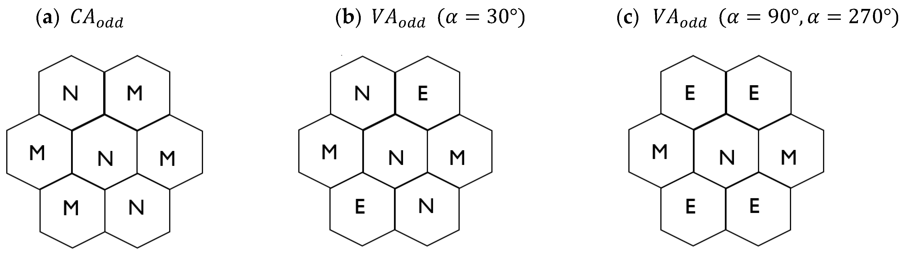
3.1.2. Packing 4-Hexagonal Clusters in the Odd-Sized CA Container

Let the architecture be C A odd , and the container size n = 2 k + 1 ,   k N . Let us consider forming 4-hexagonal clusters in the uniform clustering approach and packing the clusters in the regular hexagonal container of odd size C A odd .
Proposition 5.
If C A o d d containers are arranged in a tessellated manner, for default orientation (α = 30°) there are two types of clustering container structures.
Proof. 
The cluster contains two pairs of hexagons that are arranged in two adjacent rows. When a container size is an odd number, the width of two adjacent clusters is even number (Figure 12), which means that the third cluster will have the same structure as the first one. □
Therefore, clusters in the current cluster row have two different structures that alternate (M and N in Figure 13). Clusters in adjacent rows have the same structure but rotated for 180°.
Proposition 6.
No matter which cluster rotation is considered, there will be two clustering container types when C A o d d containers with the inner packed cluster items are tessellated, i.e., in Proposition 5, the rotational invariance is valid.
Proof. 
Like in Proposition 3, cluster rotation with angles of step 60° packed in the container with rotational symmetry (of order six) with an angle of rotation 60° results in the same clustering structure when rotated again for the step of 60° angle. Consequently, there will always be two types of clustering containers invariant of the cluster orientation. □
Clustering results from Figure 14 are summarized in Table 2, providing the number of packed inner full clusters inside the container and shared clusters at the border. It is done for both container types N and M , where the calculated numbers are denoted as N f u l l and M f u l l , and cluster orientation 30° are considered.
Again, by using the same approach, we divide the C A odd class in three sub-classes C A odd ( r ) based on the remainder of dividing by three, where n = 3 k + r , k N ,   r { 0 ,   1 ,   2 } . Also, there will always be three different clustering structures depending if the odd CA container size n is a multiple of three (refer to Proposition 4). The recursive formula is valid for N f u l l :
N f u l l i + 1 = { N f u l l i + n i 1 , f o r   r = 0 N f u l l i + n i 1 , f o r   r = 1 N f u l l i + n i , f o r   r = 2
In Equation (5), the index i is an iteration number in the recursion i N 0 , with the initial conditions n 0 = 3 and N f u l l 0 = 0 .
The number of clusters inside the central container N is:
N f u l l = { ( n 2 4 n + 7 ) / 4 , i f   r = 2 ( n 2 4 n + 3 ) / 4 , e l s e
and formula for M f u l l is obtained:
M f u l l = { ( 3 n 2 10 n + 15 ) / 12 , i f   r = 0 ( 3 n 2 10 n + 7 ) / 12 , i f   r = 1 ( 3 n 2 10 n 1 ) / 12 , i f   r = 2
Next, the number of shared clusters N s h a r e d and M s h a r e d is derived, respectively:
N s h a r e d = { 2 n , i f   r = 0 2 n 1 , e l s e
M s h a r e d = { ( 5 n ) / 3 , i f   r = 0 ( 5 n 2 ) / 3 , i f   r = 1 ( 5 n + 2 ) / 3 , i f   r = 2
Cluster Rotation Invariance: As can be seen in Figure 13, the number of inner clusters N f u l l , M f u l l , and N s h a r e d , M s h a r e d is constant for all cluster rotations (refer to Propositions 5 and 6).

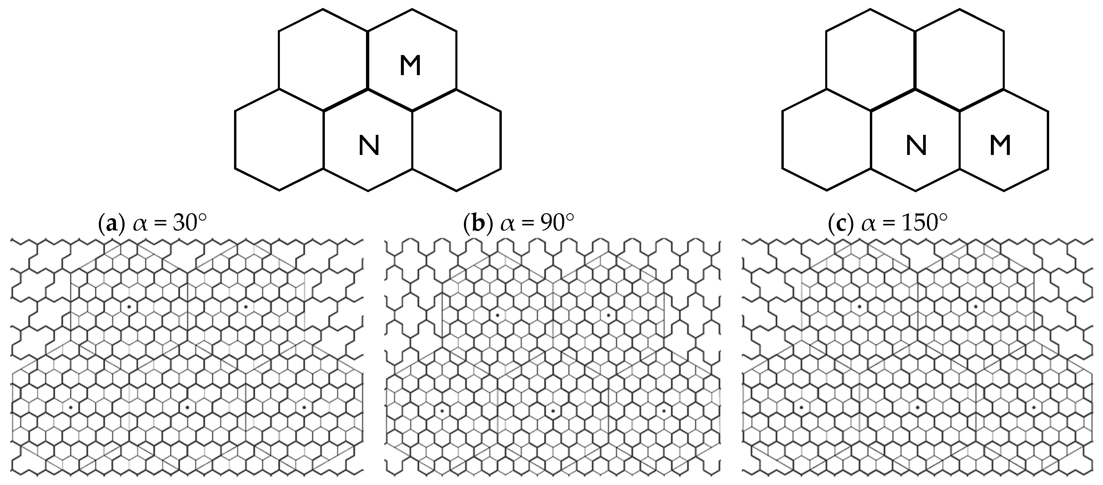
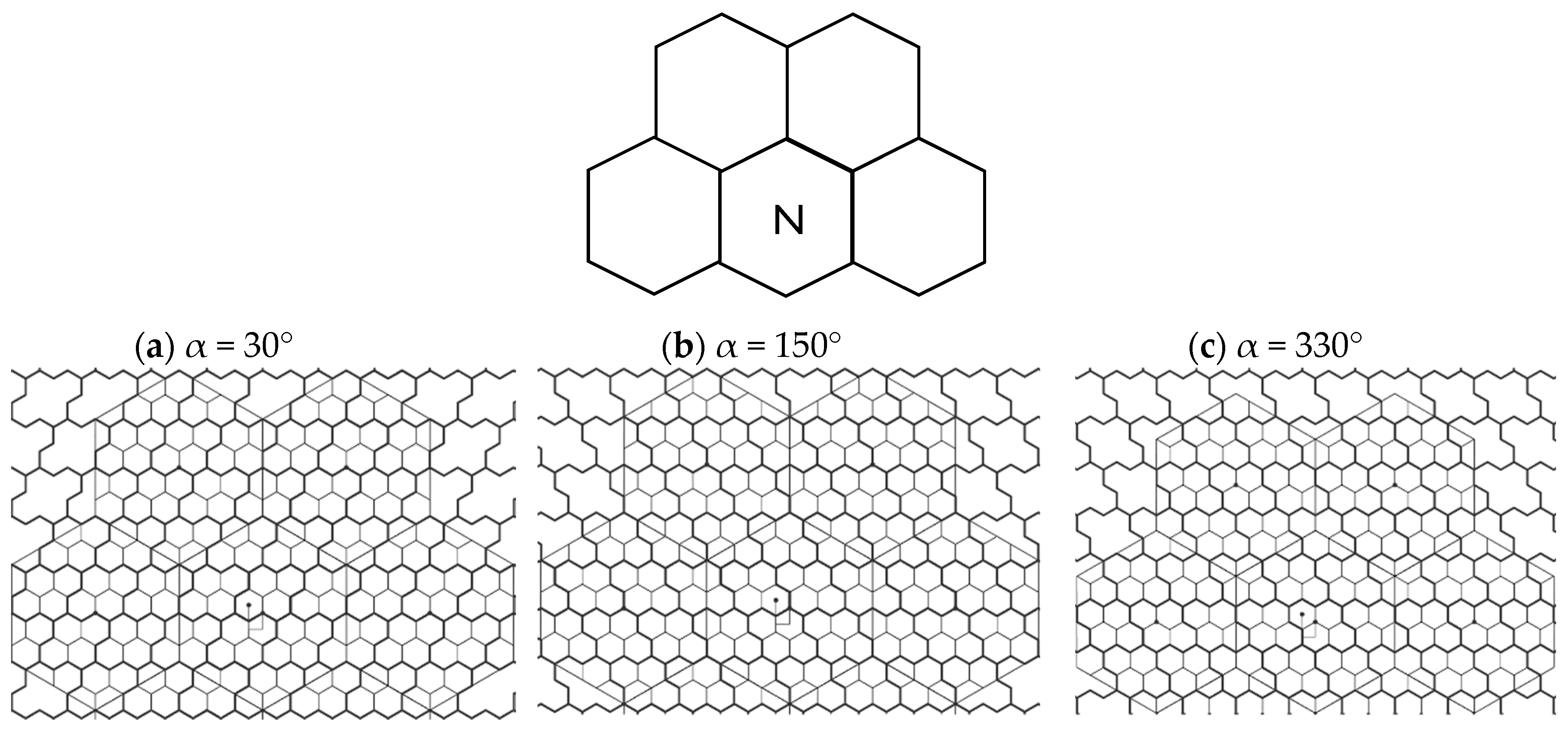
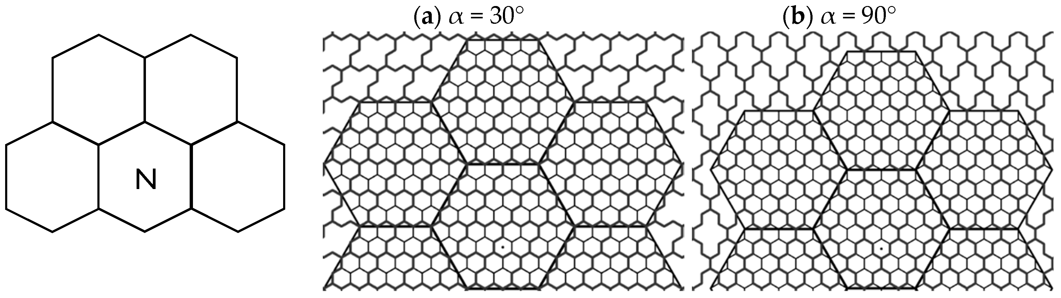
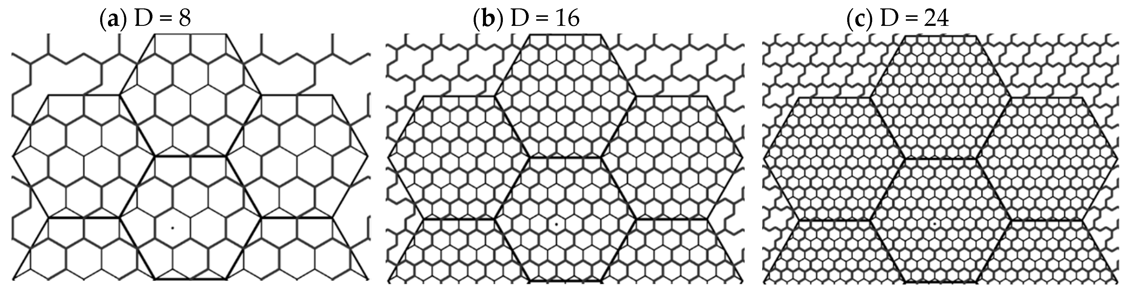
3.2. Vertex-Aligned Architecture

We use VA architecture derived from the CA model, where the container is moved such that its center does not overlap with the center but with the vertex of the central hexagonal cell (Figure 15). By applying the same notation of the R / n subdivision adopted from [12], we conclude that the same Proposition 1 about the total number of inner-packed equal hexagonal cells’ number is valid.
We adopt the described VA architecture and form 4-hexagonal clusters inside with using this existing model. Again, we divide the model into two classes, depending on whether the subdivision level n is odd or even. We refer to those classes V A o d d and V A even , respectively. Considering the requirement of the cluster plane uniformity, we examine all the cluster rotations from Figure 5.

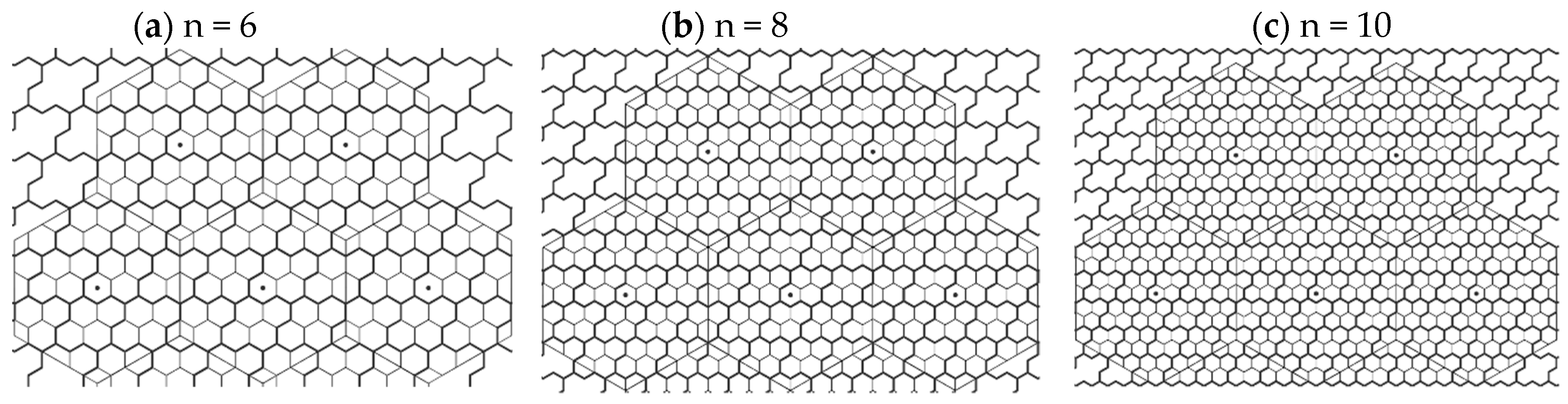
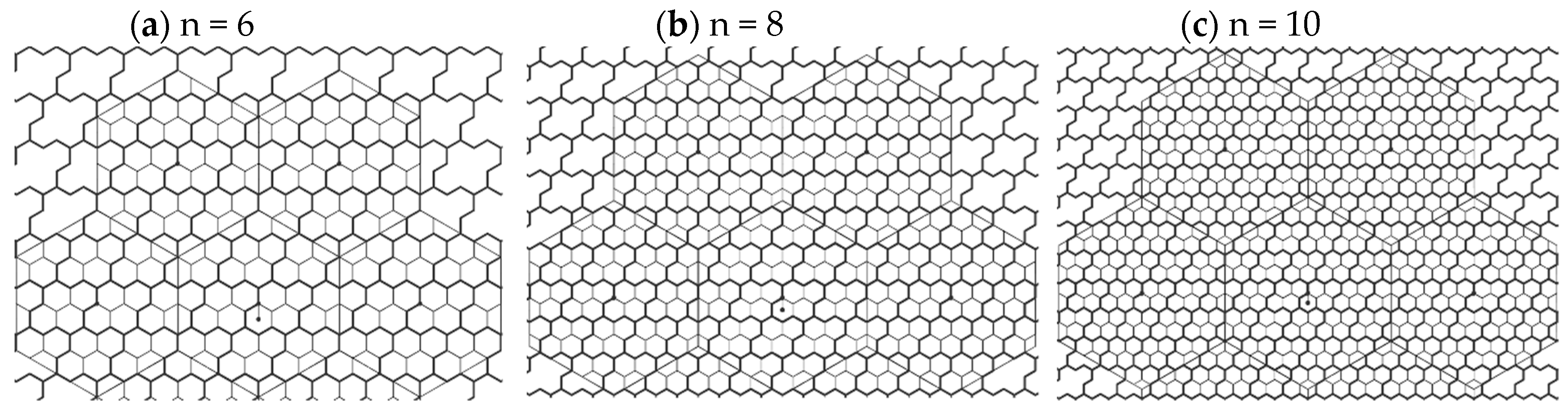
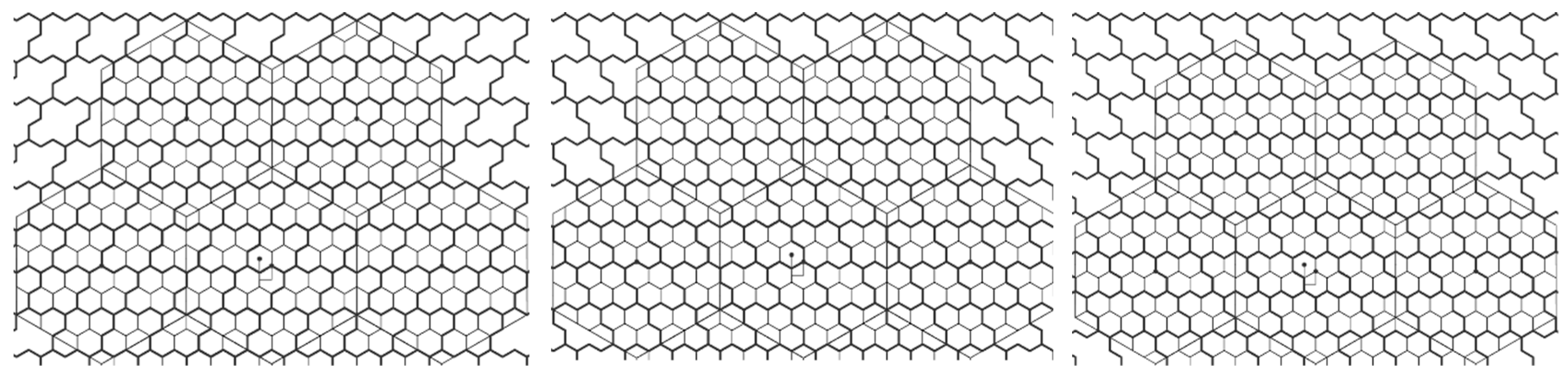
3.2.1. Packing 4-Hexagonal Clusters in the Even-Sized VA Container

Let the architecture be V A even , and the container size n = 2 k ,   k N . Let us consider forming 4-hexagonal clusters in the uniform clustering approach and packing the clusters in the regular hexagonal container of even size V A even .
Proposition 7.
If V A e v e n containers are arranged in a tessellated manner, for default orientation (α = 30°) they all have a single clustering structure.
Proof. 
Refer to Proposition 2. □
Proposition 8.
No matter which cluster rotation is considered, there will be a single structure of the tessellated V A e v e n containers with the inner packed clusters, i.e., in Proposition 7, rotation invariance is valid.
Proof. 
Refer to Proposition 2 and 3. □
Proposition 9.
No matter which center of clustering is considered (center moved down, or center moved left/right), there will be a single structure of the tessellated V A e v e n containers with the inner packed cluster items.
Proof. 
The tessellation is independent of the clustering center position. Therefore, the structure of the containers remains the same. □
VA architecture with different cluster center position is shown on Figure 16 and Figure 17. Quantitative properties of the clustering results from Figure 18 and Figure 19 are summarized in Table 3, providing the number of the packed inner full clusters inside the container and shared clusters at the border, when the default 30° cluster orientation is considered.
We derive a single algebraic expression for all even VA container sizes for calculating the number of packed cluster items:
N f u l l = ( n / 2 1 ) 2
Despite a single Equation (10) is derived, the clustering structure still depends on whether the container size n is a multiple of three. It is because the same Proposition 1 is valid in VA as in a centralized case. Therefore, we can divide the V A even class into three sub-classes V A even ( r ) based on the remainder of dividing by three (marked with r ), where n = 3 k + r , k N ,   r { 0 ,   1 ,   2 } . Also, there will always be three different clustering structures depending if the even VA container size n is a multiple of 3 (refer to Proposition 4).
We derive formulas for calculating the number of shared clusters for each architecture type V A even ( r ) . The number of shared hexagonal clusters on the container border N s h a r e d is:
N s h a r e d = { 2 n , i f   r = 1 2 n 1 , e l s e
Cluster Rotation Invariance: As it can be seen in Figure 16 (for cluster center down) and Figure 17 (for cluster center left), the number of inner clusters N f u l l and N s h a r e d is not the same for all cluster rotations. The rotation invariance is summarized in Table 4. The existing formulas are applied in almost all cases, while for cluster rotation angle α = 270° and the architecture moved down, the following formula is used to calculate the number of full clusters:
N f u l l = { ( 3 n 2 10 n ) / 12 , i f   r = 0 ( 3 n 2 10 n + 16 ) / 12 , i f   r = 1 ( 3 n 2 10 n + 8 ) / 12 , i f   r = 2

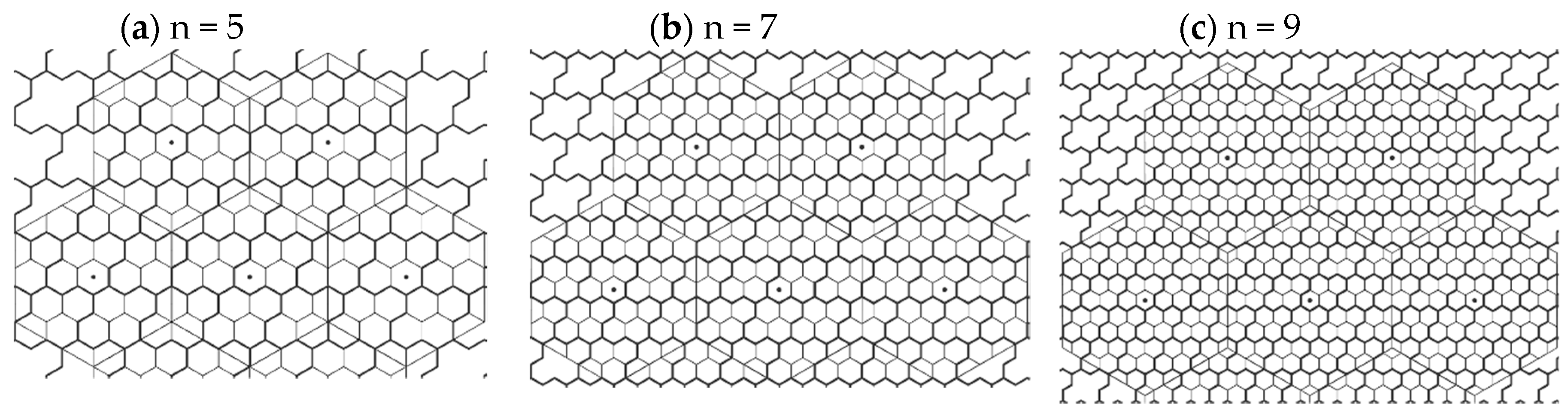
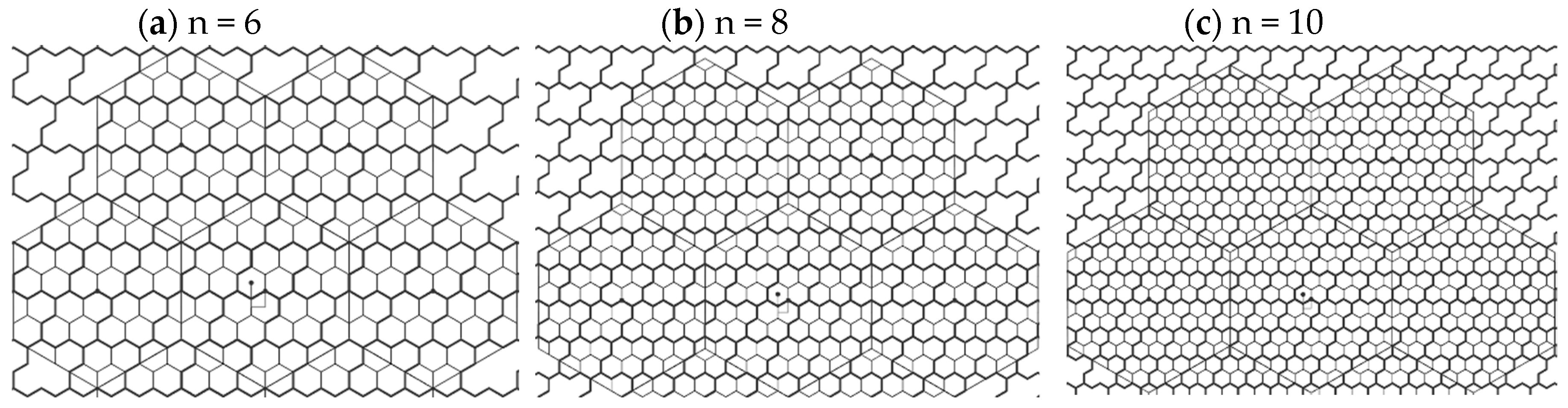
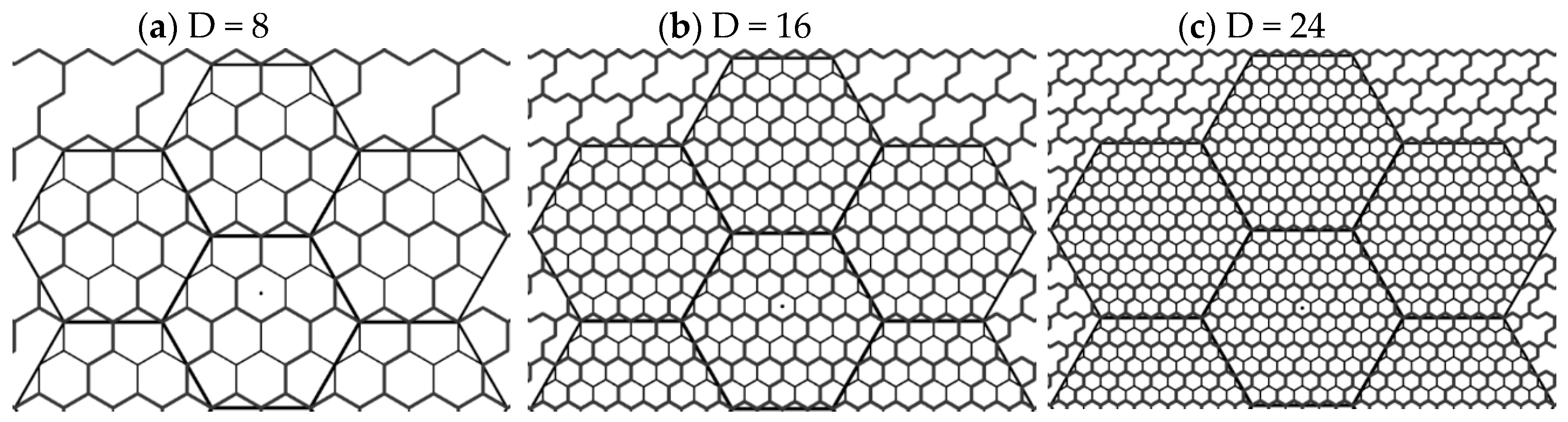
3.2.2. Packing 4-Hexagonal Clusters in the Odd-Sized VA Container

Let the architecture be V A odd , and the container size n = 2 k + 1 ,   k N . Let us consider forming 4-hexagonal clusters in the uniform clustering approach and packing the clusters in the regular hexagonal container of odd size V A odd .
Proposition 10.
There are three types of clustering container structures when V A o d d containers with packed cluster items are arranged in a tessellated manner for default orientation (α = 30°).
Proof. 
Like Proposition 5, if container size is an odd number, the width of two adjacent clusters is even number meaning that the third cluster will have the same structure as the first one. Therefore, clusters in the current cluster row have two different structures (N and M). Clusters in the adjacent row also have two different structures that alternate, but one of them is reflectively symmetrical with one of structures N or M. Hence, altogether, there are three types of clustering container structures. □
Proposition 11.
No matter which cluster rotation is considered, there will be three clustering container types when V A o d d containers with the inner packed cluster items are tessellated, i.e., the Proposition 10 is rotation invariant (Figure 20).
Proof. 
Refer to Proposition 6. □
Proposition 12.
No matter which center of clustering is considered (center moved down, or center moved left/right), there will be three different structures of the tessellated V A e v e n containers with the inner packed cluster items (Figure 21).
Proof. 
Refer to Proposition 9. □
Clustering results from Figure 22 and Figure 23 are summarized in Table 5, providing the number of the packed inner full clusters inside the container and shared clusters at the border. It is shown for all three container types N , M , and E , denoted as N f u l l , M f u l l , and E f u l l , where the default α = 30° cluster orientation is considered. Also, there will always be three different clustering structures depending if the odd VA container size n is a multiple of three (refer to Proposition 4).
Again, by using the same approach, we divide the V A odd class in three sub-classes V A odd ( r ) based on the remainder of dividing by 3, where n = 3 k + r , k N ,   r { 0 ,   1 ,   2 } . The recursive formula is valid for N f u l l :
N f u l l i + 1 = { N f u l l i + n i , f o r   r = 2 N f u l l i + n i 1 , e l s e
In Equation (13), the index i is an iteration number in the recursion, i N 0 , with the initial conditions n 0 = 3 and N f u l l 0 = 0 .
The number of full hexagonal clusters N f u l l packed inside the container is:
N f u l l = { ( 3 n 2 10 n + 3 ) / 12 , i f   r = 0 ( 3 n 2 10 n + 7 ) / 12 , i f   r = 1 ( 3 n 2 10 n + 11 ) / 12 , i f   r = 2
E f u l l is calculated in formula (6), while formulas for calculating M f u l l are:
M f u l l = { ( n 2 4 n 1 ) / 4 , i f   r = 2 ( n 2 4 n + 7 ) / 4 , e l s e
Next, the number of shared clusters for each container type, i.e., N s h a r e d , M s h a r e d and E s h a r e d is derived in continuation:
N s h a r e d = { ( 5 n ) / 3 , i f   r = 0 ( 5 n + 1 ) / 3 , i f   r = 1 ( 5 n 1 ) / 3 , i f   r = 2
M s h a r e d = { 2 n 2 , i f   r = 1 2 n , e l s e
E s h a r e d = { 2 n 2 , i f   r = 0 2 n + 1 , i f   r = 1 2 n 1 , i f   r = 2
Cluster Rotation Invariance: As it can be seen in Figure 20 (for cluster center down) and Figure 21 (for cluster center left), the number of inner clusters N f u l l , M f u l l , E f u l l and N s h a r e d , M s h a r e d , E s h a r e d is not the same for all cluster rotations. The rotation invariance is summarized in Table 6, where we can see that formulas are permutated depending on the chosen N , M and E type.

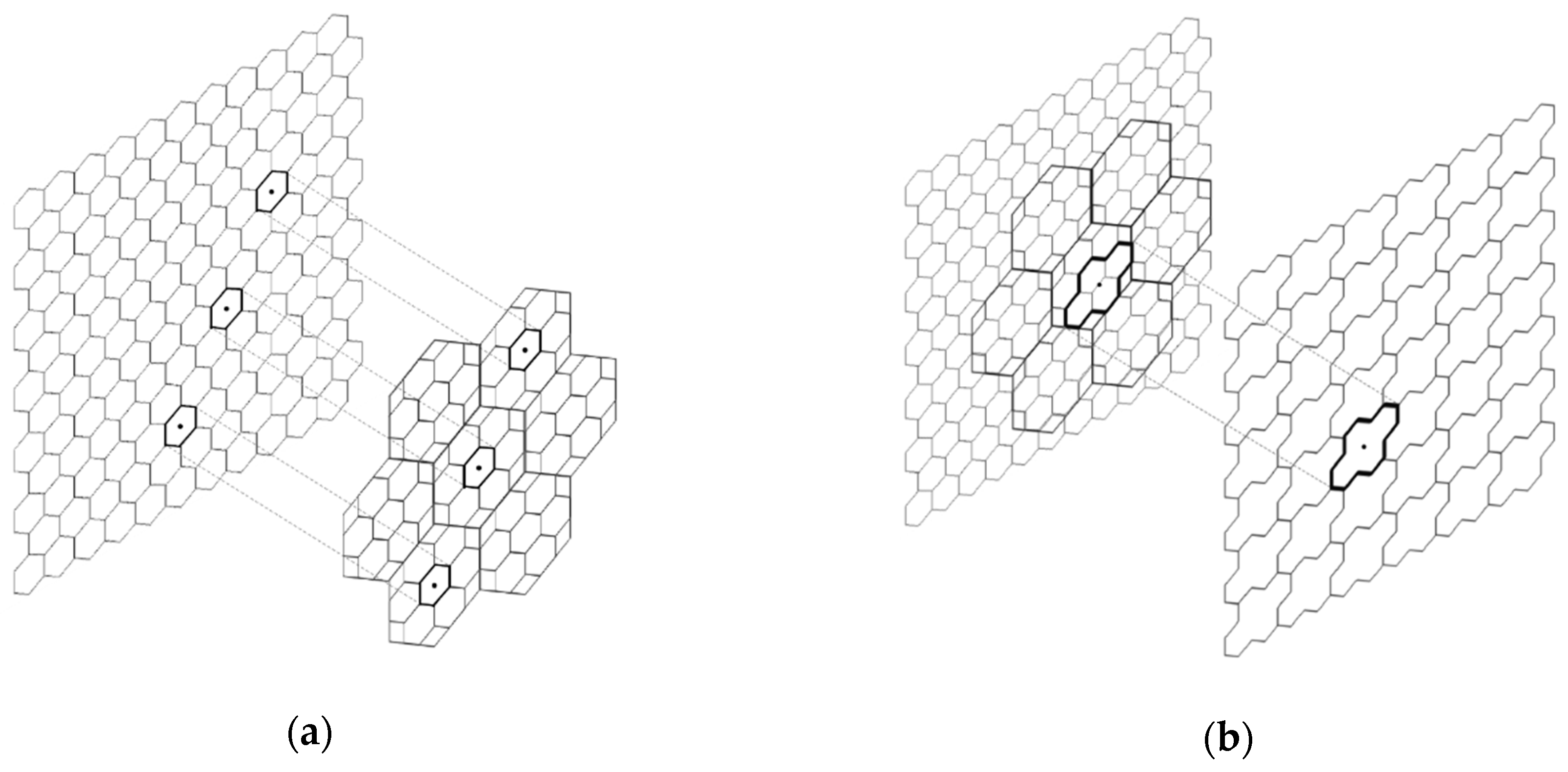
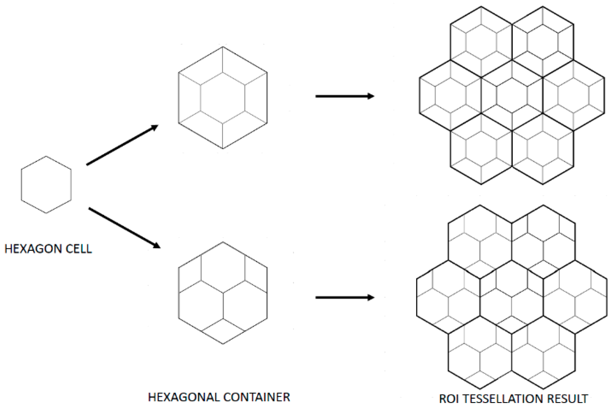
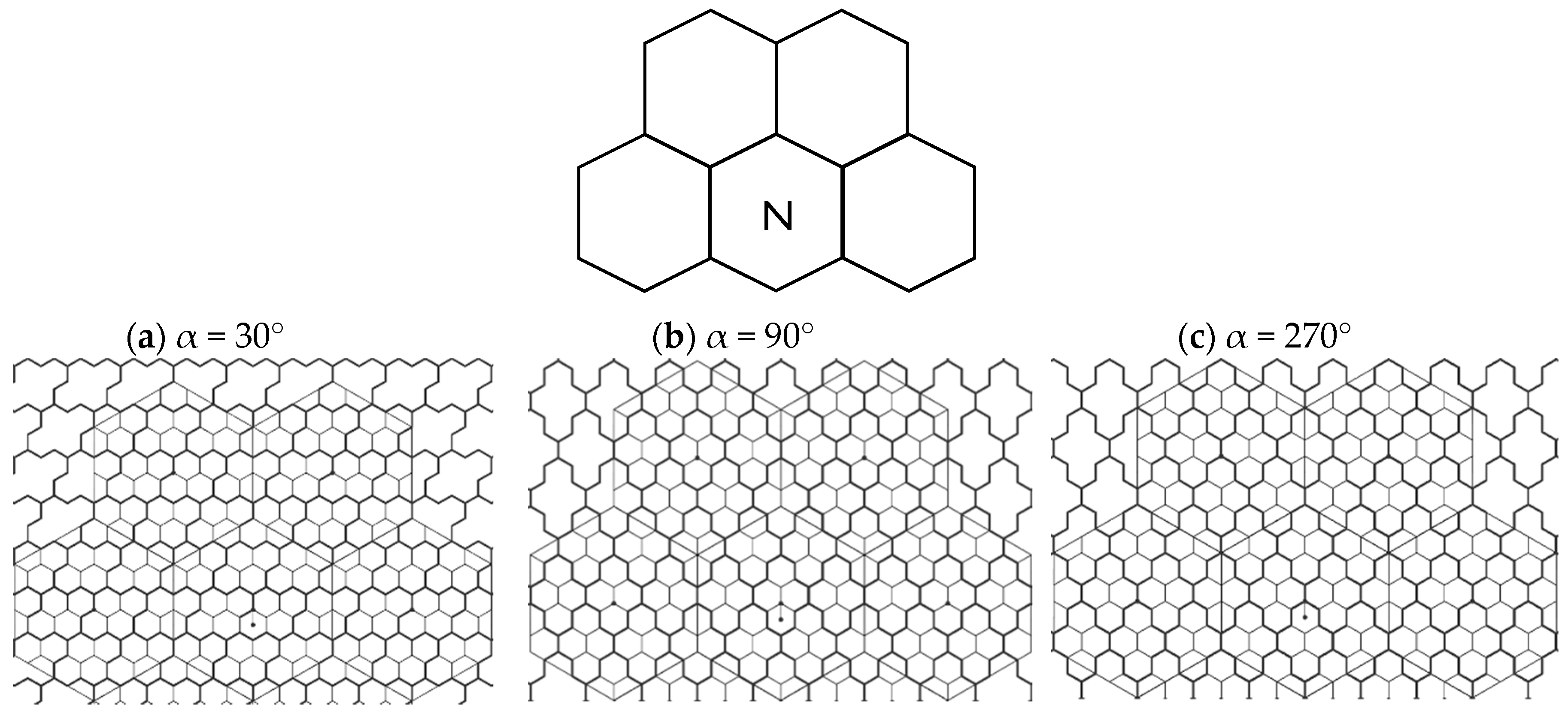
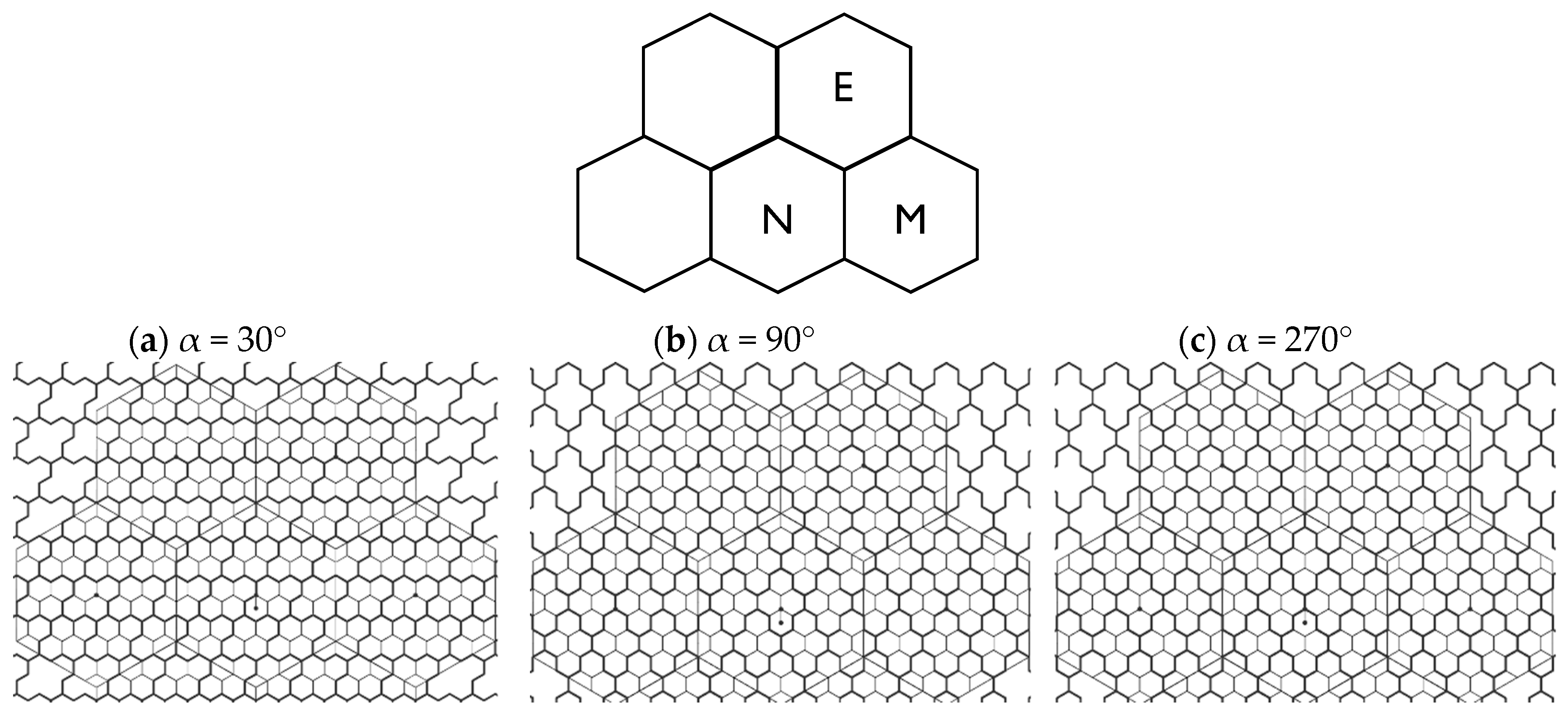
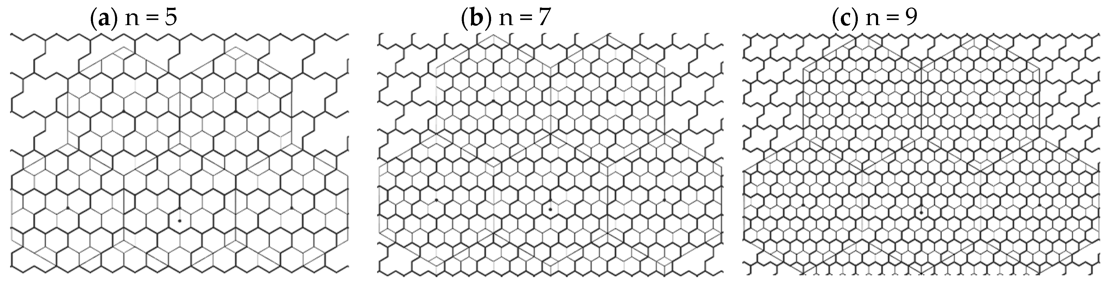
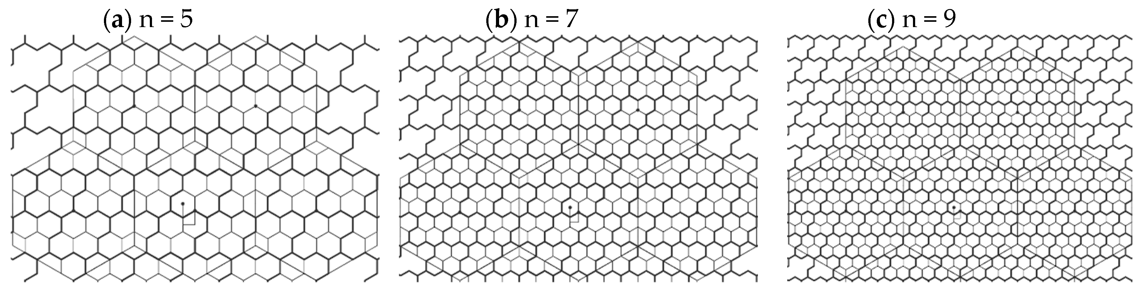
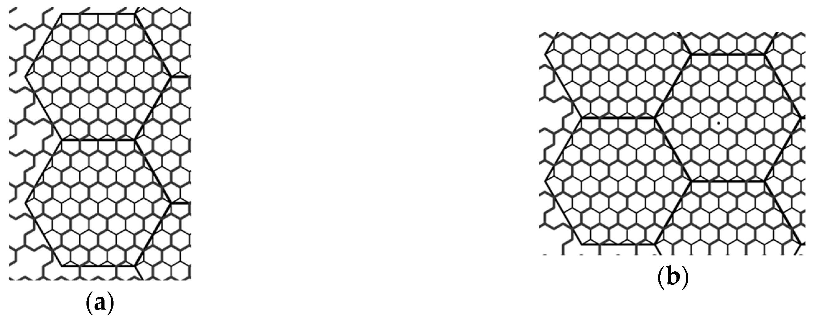
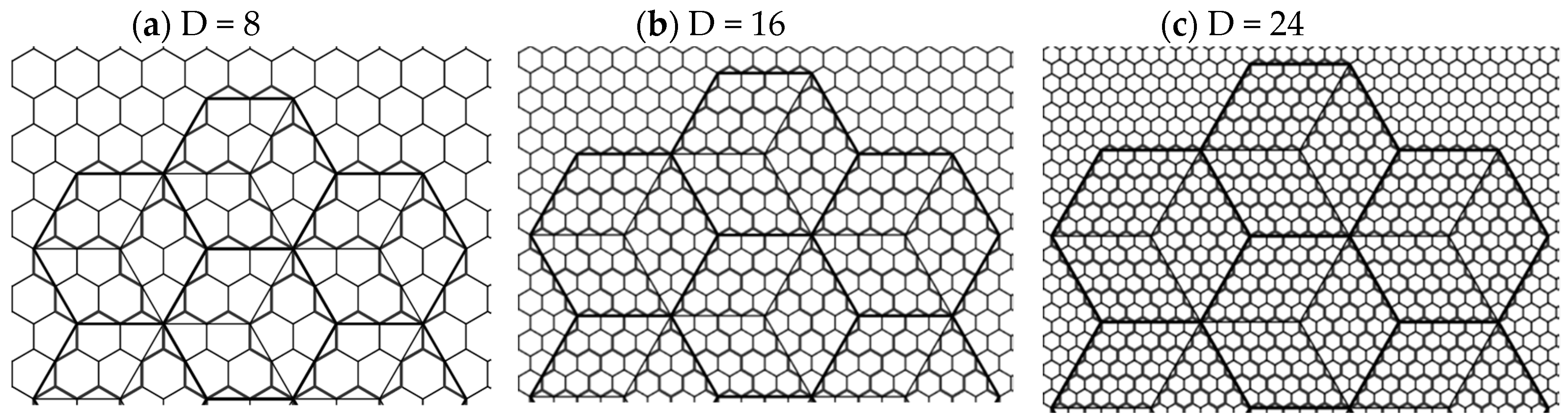
4. The Proposed Vertex-Aligned Architecture

4.1. General Description

We propose a structure for more efficient packing of the 4-hexagonal clusters in the regular hexagonal container. It is adapted from [29], where its formal definition is described. Namely, the model can be referred to as H ( D ) , where D = 8 k ,   k N is a total number of inner small hexagonal edges, situated on the circumscribed circle diameter of the hexagonal container. Example for D = 8 and the corresponding tessellation results are given in Figure 24.

4.2. Uniform Clustering with the Proposed Model

We propose a uniform clustering with the proposed model. Again, like in the case of CA and VA, we choose one of the hexagonal cells that is closest to the real container center to be the clustering center. As shown in Figure 25, we have three possibilities: central cluster position down, central cluster position left (symmetric to position right), and central cluster position up.
It can be seen, for instance, in Figure 25a that there will be some compromises at the container border. Namely, instead of four full hexagons forming the 4-hexagonal cluster, some clusters at the container border will be smaller in area, as they consist of two full hexagons and two truncated hexagon pieces (Figure 26). However, the difference in the cluster area is acceptable ( 9.1 % ). Also, there are voids on some container edges, given in the form of several cut-out triangles.

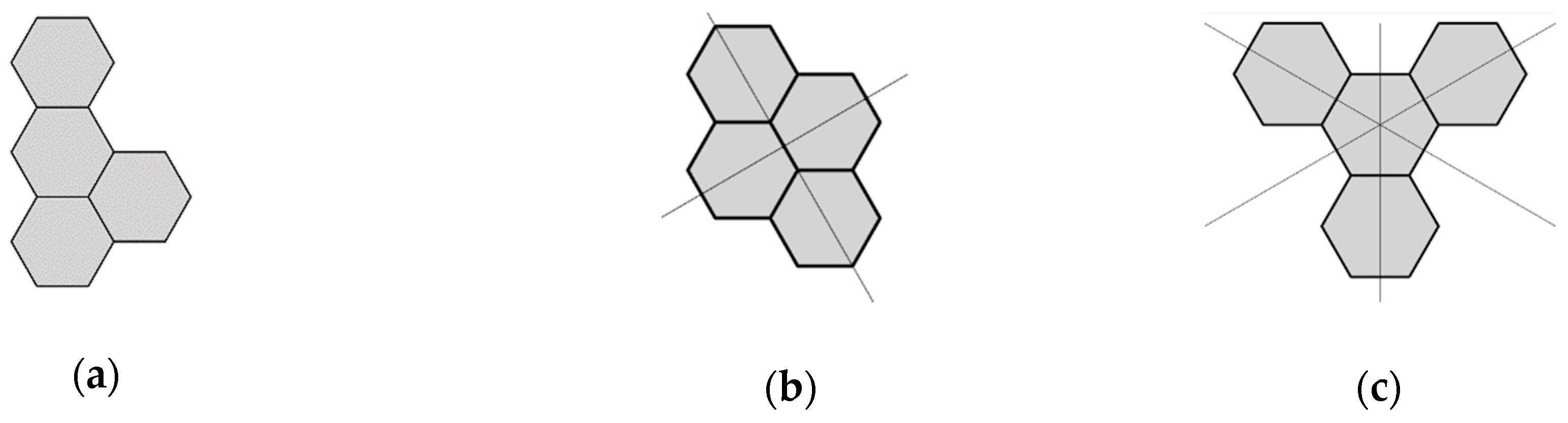
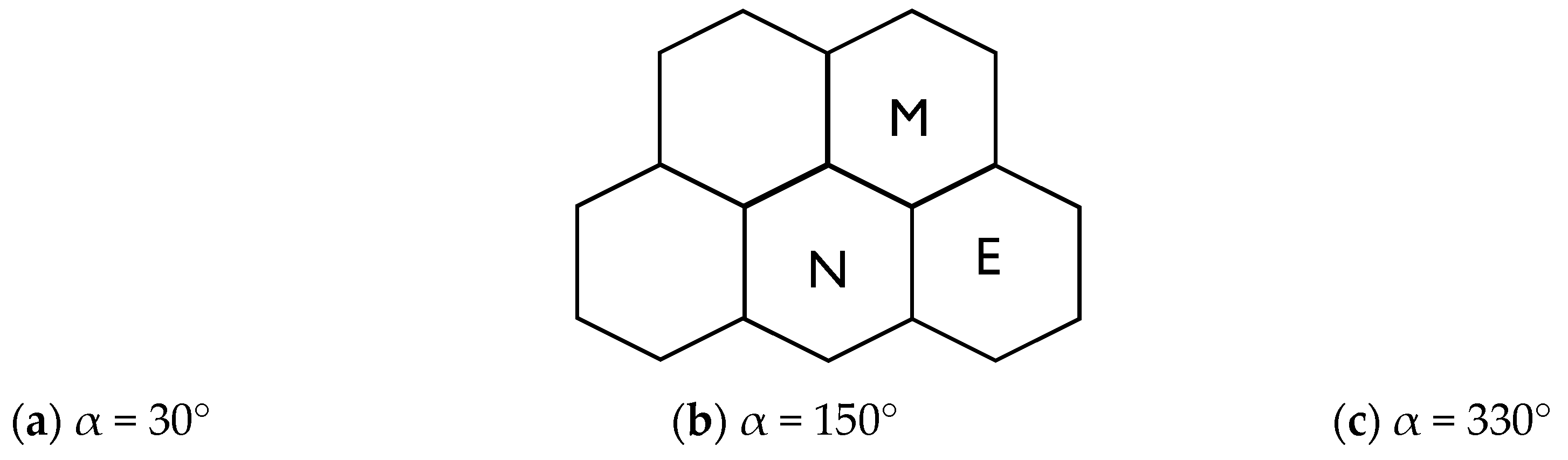
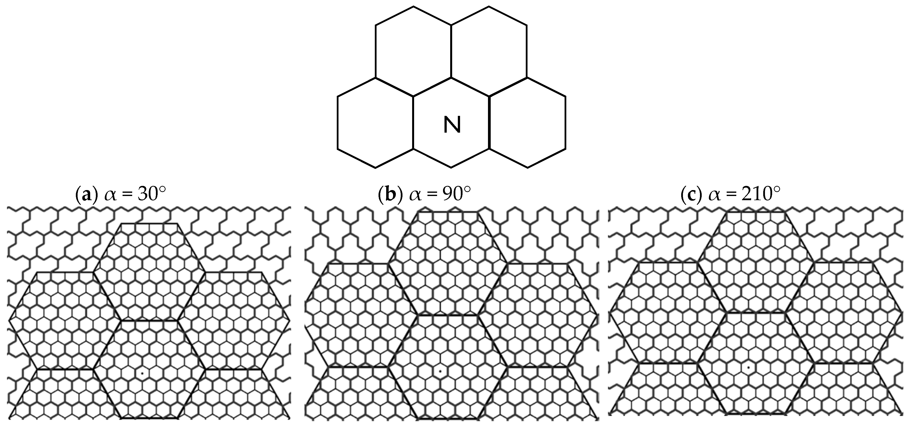
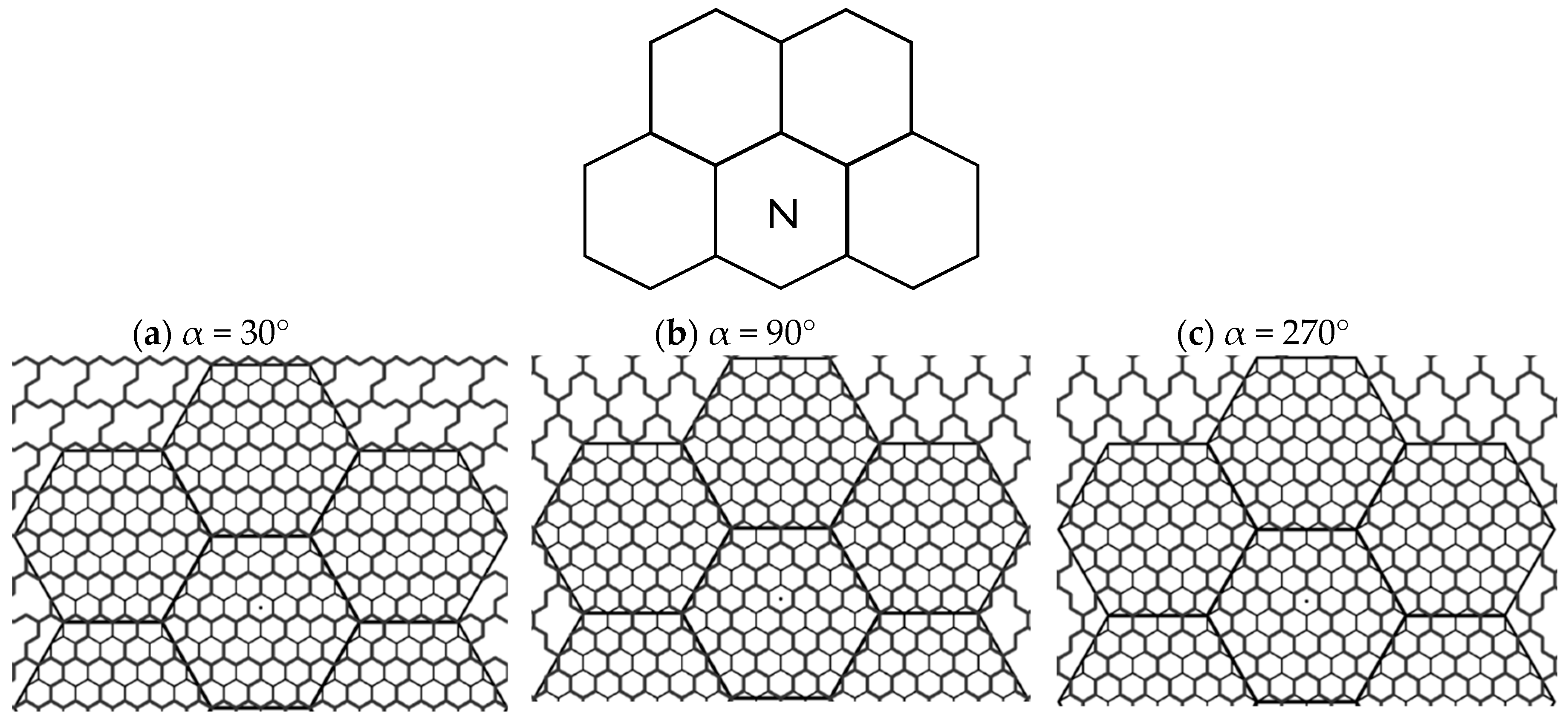
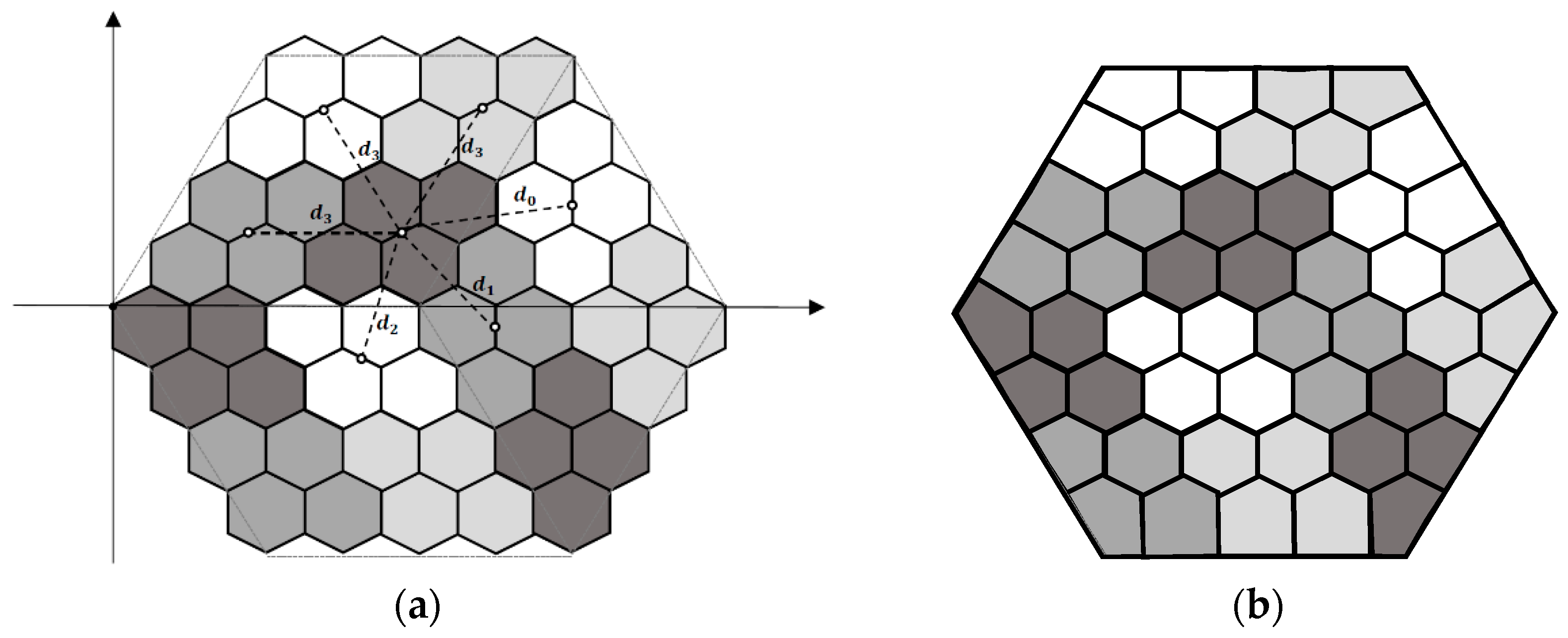
4.2.1. The 4-Hexagonal Cluster Rotations

If we consider the cluster rotations for this type of architecture, depending of the cluster center position, different cases can be distinguished. For the cluster center position down, two groups of orientations having the same clustering structure are the first one 30°, 150° and 270° and the other one 90°, 210° and 330°. In the case of cluster center position left, there are three (groups of) orientations having the same structure: 30°, then 90°, 150°, 270°, and 330° are the same, and the third type is 210° orientation. Finally, for cluster center position up, there are three possible (groups of) orientations with constant structure: 30°, then 90°, 150°, 210°, and 330° having the same structure, and the last one type is 270° orientation.

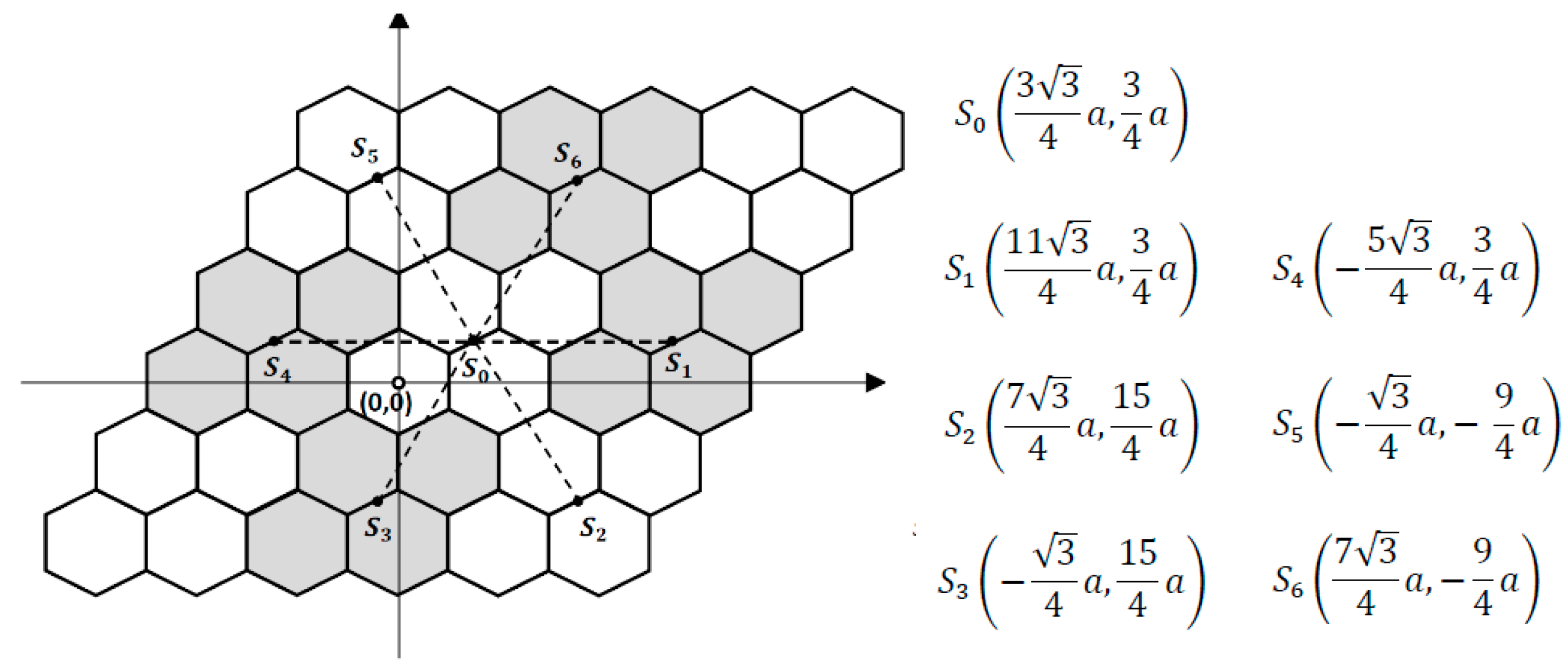
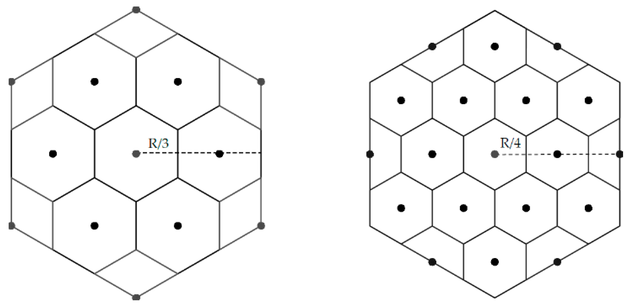
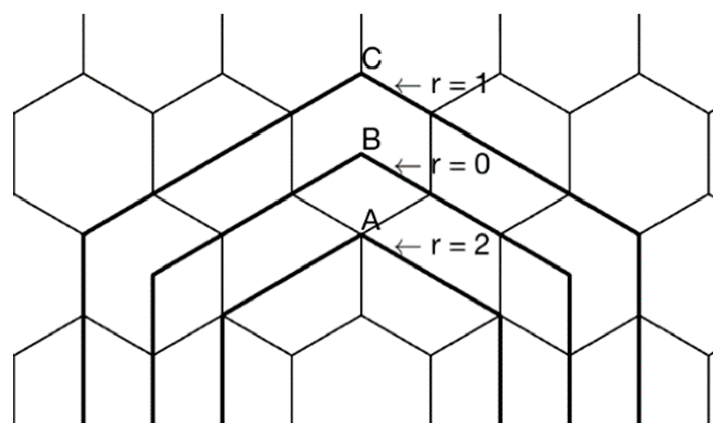
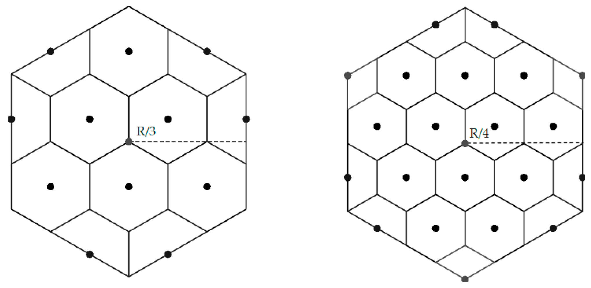
4.2.2. The Geometrical Properties and Derived Formulas

Let the architecture be H ( D ) , and the container size D = 8 k ,   k N . Let us consider forming 4-hexagonal clusters in the uniform clustering approach and packing the clusters in the proposed regular hexagonal container.
Proposition 13.
If H ( D ) containers are arranged in a tessellated manner, for default orientation (α = 30°), they all have a single clustering structure.
Proof. 
Like in the case of even-sized CA container type, since D = 8 k , the H ( D ) container contains even number of hexagons between two opposite hexagon sides. Therefore, all containers in the current container column have the same structure (Figure 27a). The containers in adjacent columns are the same as the previous one but translated, as shown in Figure 27b. □
Proposition 14.
No matter which cluster rotation is considered, there will be a single structure of the tessellated H ( D ) containers with the inner packed cluster items, i.e., in Proposition 13, rotation invariance is valid.
Proof. 
Refer to Proposition 3. □
Proposition 15.
No matter which center of clustering is considered (center moved down/up, or center moved left/right), there will be a single structure of the tessellated H ( D ) containers with the inner packed cluster items.
Proof. 
The tessellation is independent of the clustering center position. Therefore, the choice of clustering center doesn’t have an influence on the containers structure (Figure 28, Figure 29 and Figure 30). □
Clustering results from Figure 31 are summarized in Table 7, providing the number of inner full clusters packed inside the container and the number of shared clusters at the border, when the default 30° cluster orientation is considered.
An algebraic expression for calculating the number of inner packed cluster items is as follows:
N f u l l = ( 3 D 2 8 D ) / 64
Also, the number of shared clusters at the container border is calculated as:
N s h a r e d = D / 4
Clustering results from Figure 32 are summarized in Table 8, providing the number of the inner full clusters packed inside the container and the number of shared clusters at the border, when the default 30° cluster orientation is considered.
An algebraic expression for calculating the number of inner packed cluster items is as follows:
N f u l l = ( 3 D 2 24 D + 64 ) / 64
Also, the number of shared clusters at the container border is calculated as:
N s h a r e d = ( 3 D ) / 4
Clustering results from Figure 33 are summarized in Table 9, providing the number of the inner full clusters packed inside the container and the number of shared clusters at the border, when the default 30° cluster orientation is considered.
An algebraic expression for calculating the number of inner packed cluster items is as follows:
N f u l l = ( 3 D 2 16 D ) / 64
Also, the number of shared clusters at the container border is calculated as:
N s h a r e d = D / 2
Cluster Rotation Invariance: As it can be seen in Figure 28 (for cluster center down), Figure 29 (for cluster center left) and Figure 30 (for cluster center up), the number of clusters N f u l l and N s h a r e d is not the same for all cluster rotations. The rotation invariance is summarized in Table 10.

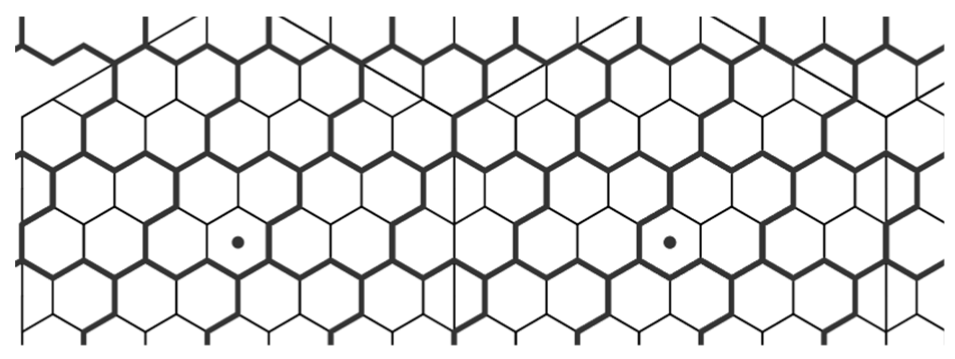
4.3. The Proposed Non-Uniform Clustering Approach

We propose another clustering model that is non-uniform. Inspired by [31], the orientation of the tetrahex clusters is rotated by 120° on each of the container thirds. The non-uniformity is present in the cluster plane, as the distance to all NN clusters is not constant (Figure 34a).
We claim that in this proposed architecture, all clusters are entirely contained inside the container with no shared clusters at the border. Again, as already given in Figure 25a, the truncated tetrahexes exist in the clustering procedure, which are now present on three edges of the container. There are voids on the remaining three container edges, in the form of several cut-out triangles. In order to obtain the full benefit of the hexagonal tessellation approach and to eliminate voids inside the container, the model shown in Figure 34b will be used in the future CMS HGCAL. Modified tetrahex cluster areas at the container vertex are very close to the real tetrahex (≈1% difference in average).
An example of packing clusters with the proposed model H ( D ) is given in Figure 35.
Clustering results presented in Figure 35 are quantized in Table 11, based on which we derive the corresponding algebraic expressions.
In this clustering approach, there are no shared clusters at the container border, since they are all contained in the container inner part. Thus, the number of full clusters is calculated with the following formula:
N f u l l = 3 D 2 / 64

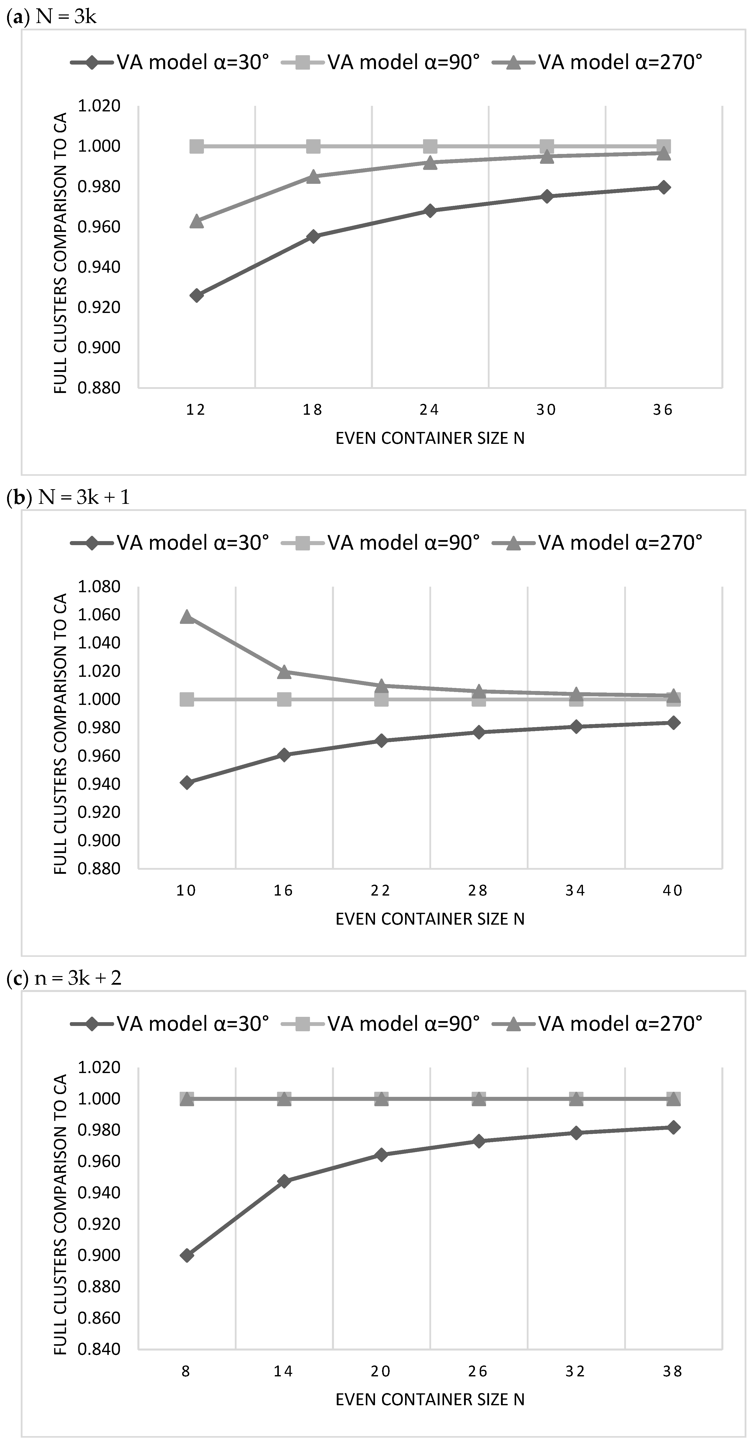
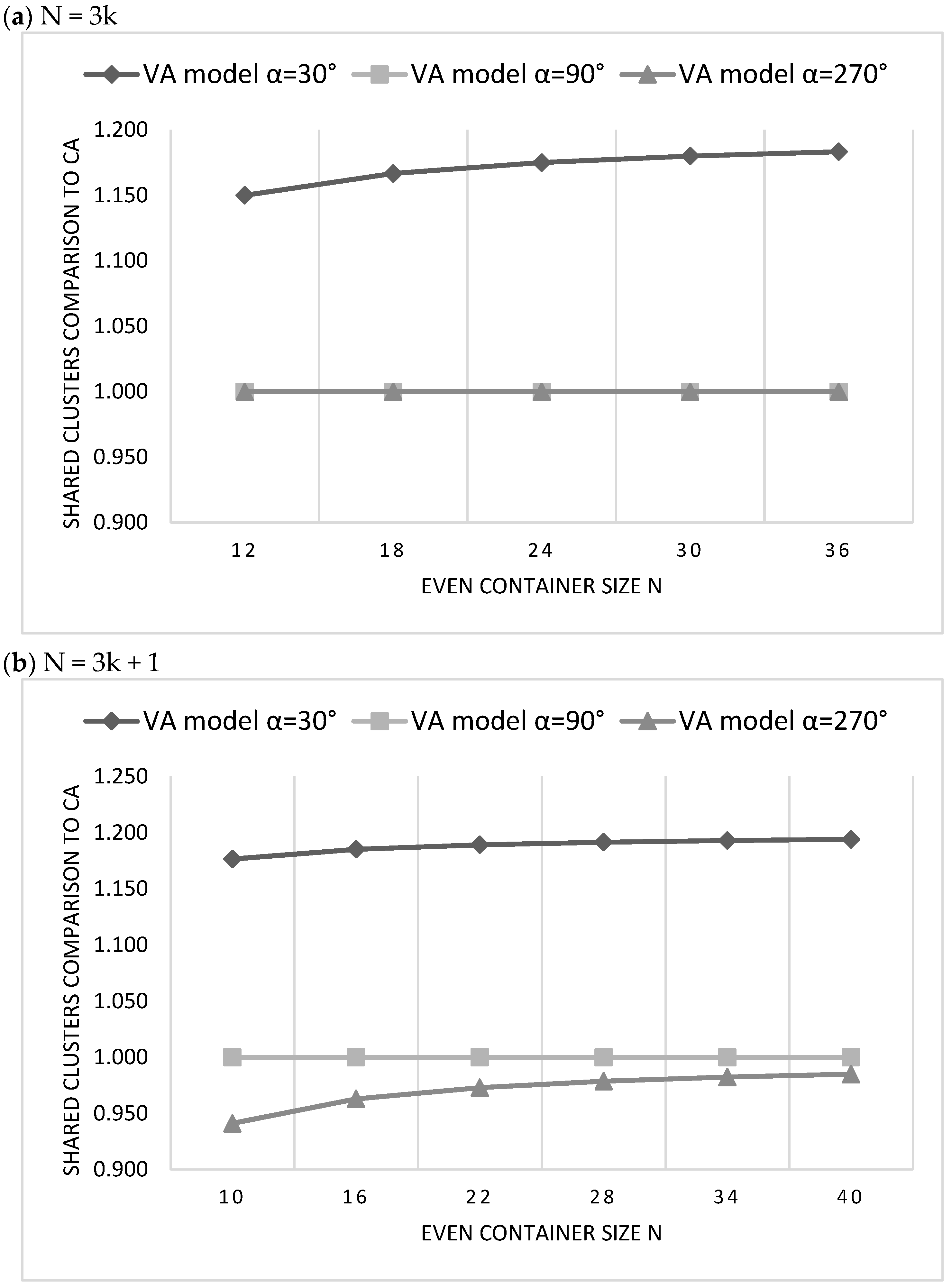
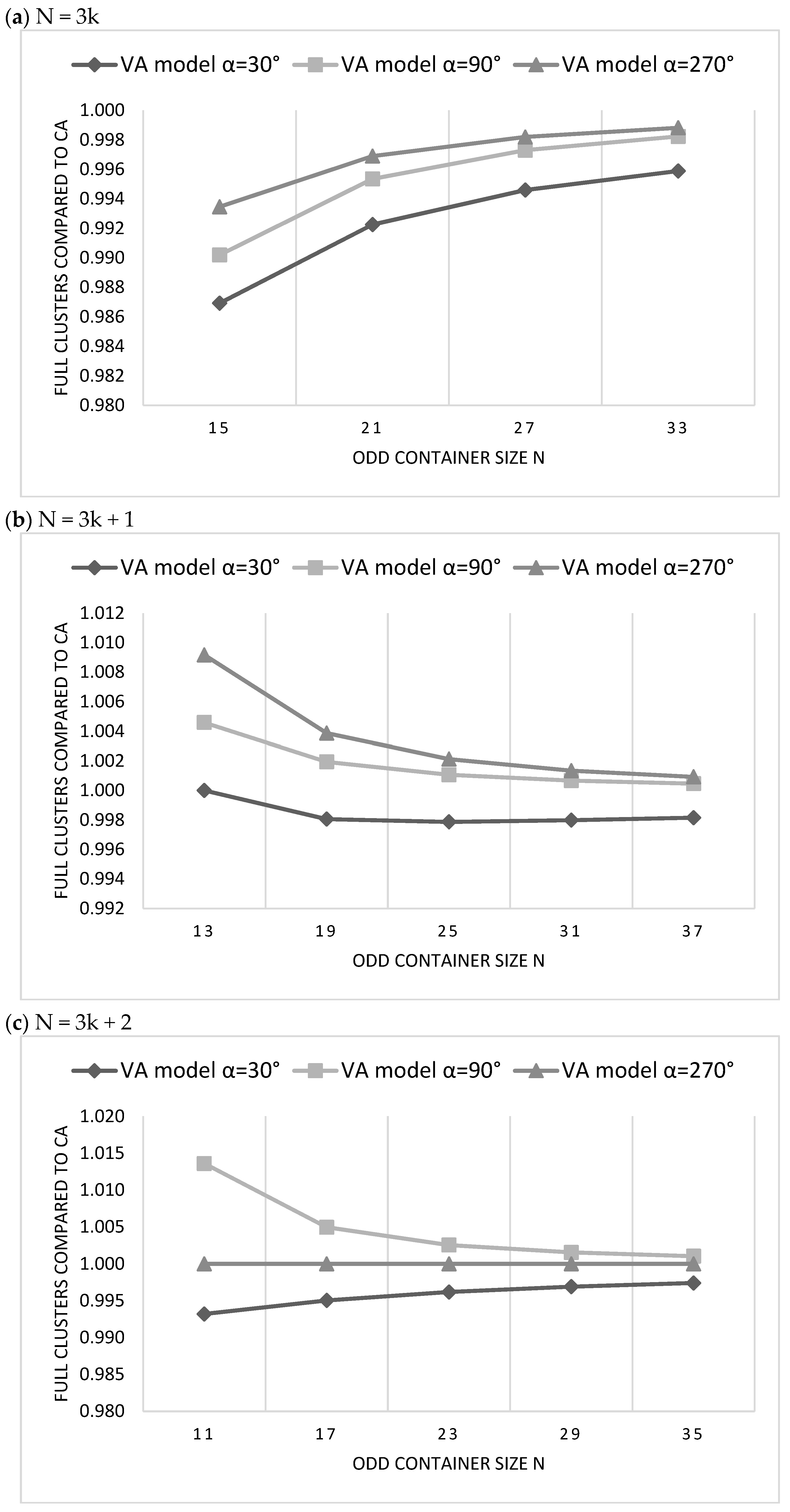
5. Evaluation and Results

5.1. Summary of the Presented Models

We have shown there are different variations of presented models based on container size, container center position, cluster orientation, or if the void space is allowed or not. We give a brief summary of the presented models in Table 12, together with the models that we have chosen for the comparison.

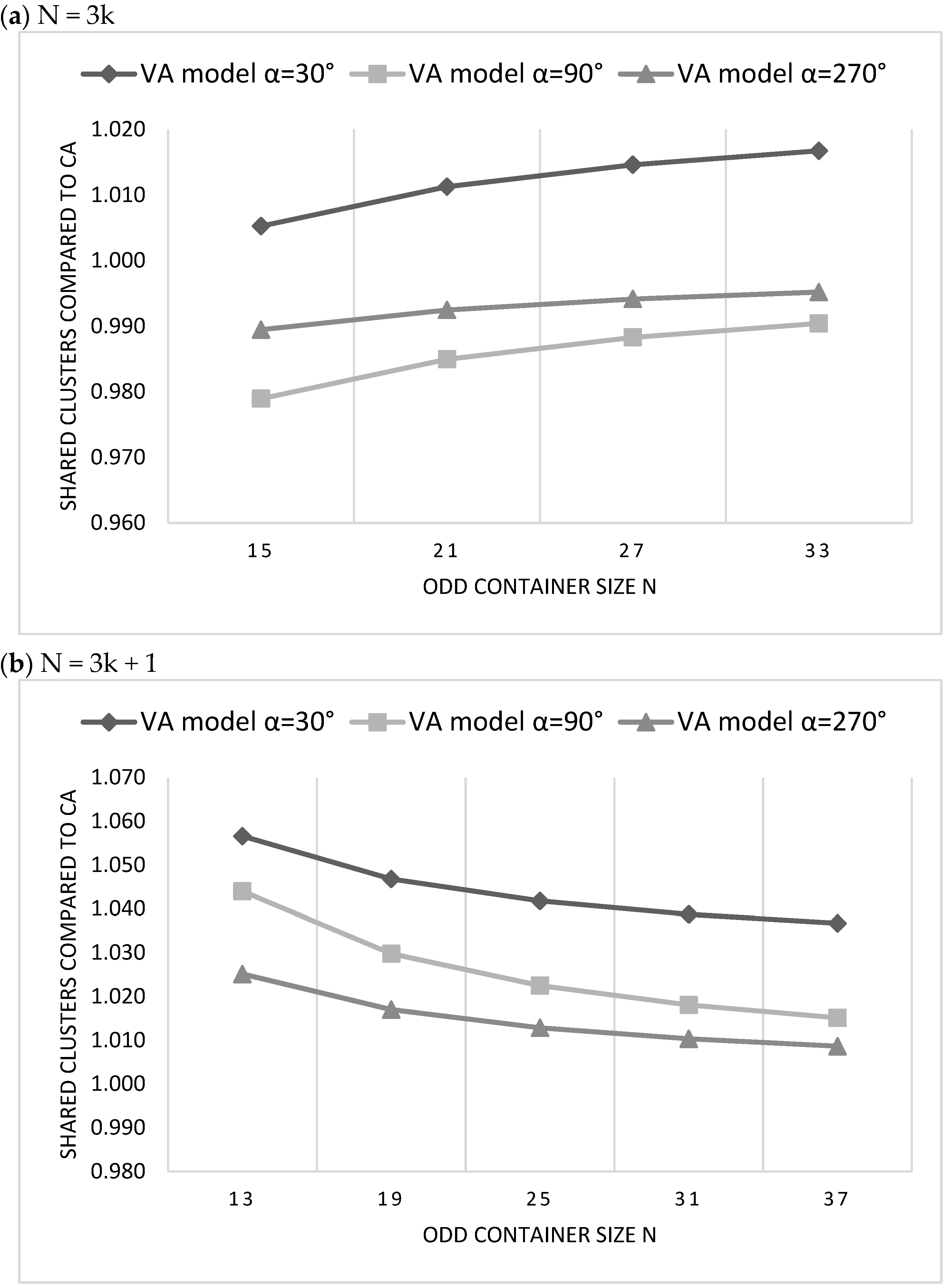
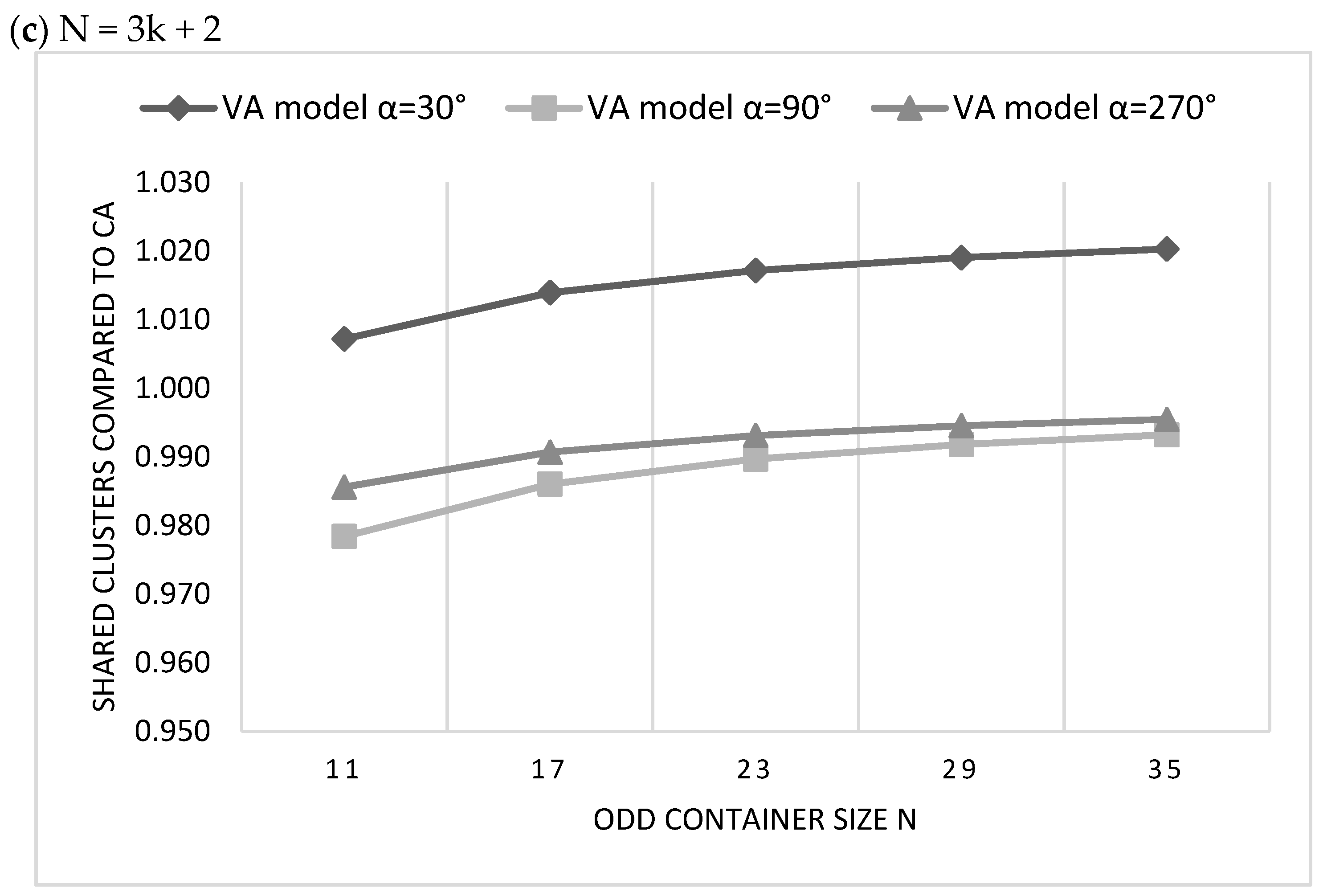
5.2. The Comparison of CA and VA Clustering Architectures

To compare even architectures, we apply Formula (1), Formula (3), Formula (10), Formula (12) to calculate N f u l l and Formula (4), Formula (9), Formula (11) for N s h a r e d . Figure 36 and Figure 37 present the evaluation of even VA architectures (moved down) compared to CA even, given in the form of the ratio N f u l l ( V A ) / N f u l l ( C A ) and N s h a r e d ( V A ) / N s h a r e d ( C A ) . Hence, result 1 means the measured parameter is same or larger than CA, while result < 1 means that it is lower. We show that the VA model for α = 30° is the least efficient in clustering, causing the smallest number of full clusters packed, and the largest number of shared clusters for each container size n . Also, the VA model for α = 90° is the same as the CA in all measurement cases, and this model is the best for container size n = 3 k or n = 3 k + 2 . If n = 3 k + 1 , the VA model α = 270° is the most efficient due to the larger number of full clusters than CA and the lowest number of shared clusters at the border.
The comparison in Figure 36 and Figure 37 is based on even containers, where a single container type N is present independent of how many rings of containers there are tessellated in the clustering plane. However, we already concluded that the number of different container types is larger for odd than for even container sizes. Hence, there will be several container configurations in a single tessellation ring depending on the container size, and we show them in Figure 38. We approximate the number of full and shared clusters in a single container ring with the formulas presented, to obtain a fair comparison of architectures.
To compare odd architectures, we apply configurations based on Formula (6), Formula (7), Formula (14), Formula (15) to calculate N f u l l and Formula (8), Formula (9), Formula (16), Formula (17), Formula (18) for N s h a r e d . We can see in Figure 39 and Figure 40 that the VA model for α = 30° is the worst among odd clustering architectures since there are the most shared clusters in the container ring for the lowest number of inner full clusters. On the other hand, VA model α = 270° is the most efficient in all cases for n = 3 k and n = 3 k + 2 , while for n = 3 k + 1 the VA model α = 90° is the best, as there are more full clusters than CA in the container ring.
It is shown in Figure 39a that the odd CA is more efficient than any odd VA model for n = 3 k , having the largest number of full clusters in the container ring. If we compare VA models, VA α = 270° is the best, being closest to CA efficiency. However, as shown in Figure 40a, VA models α = 90° and α = 270° are better to use than CA if the goal is not to maximize the number of clusters packed, but to minimize the number of shared clusters.
In addition, all odd VA models are less efficient than CA (Figure 40b), causing larger cluster sharing, even though the number of full clusters is enhanced in the VA case (Figure 39b).

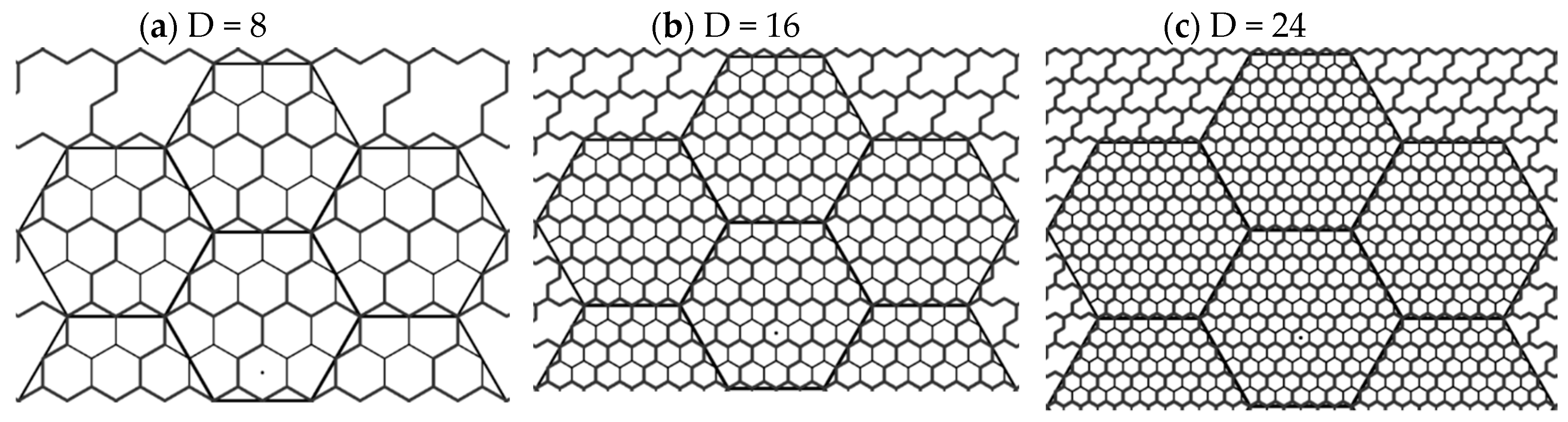
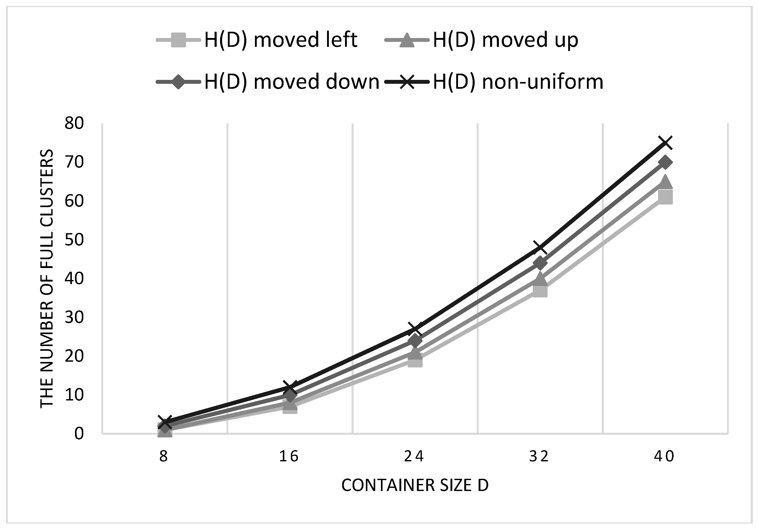
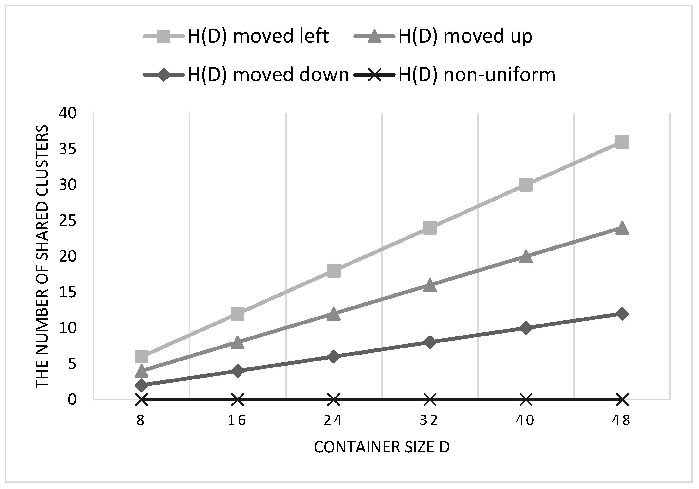
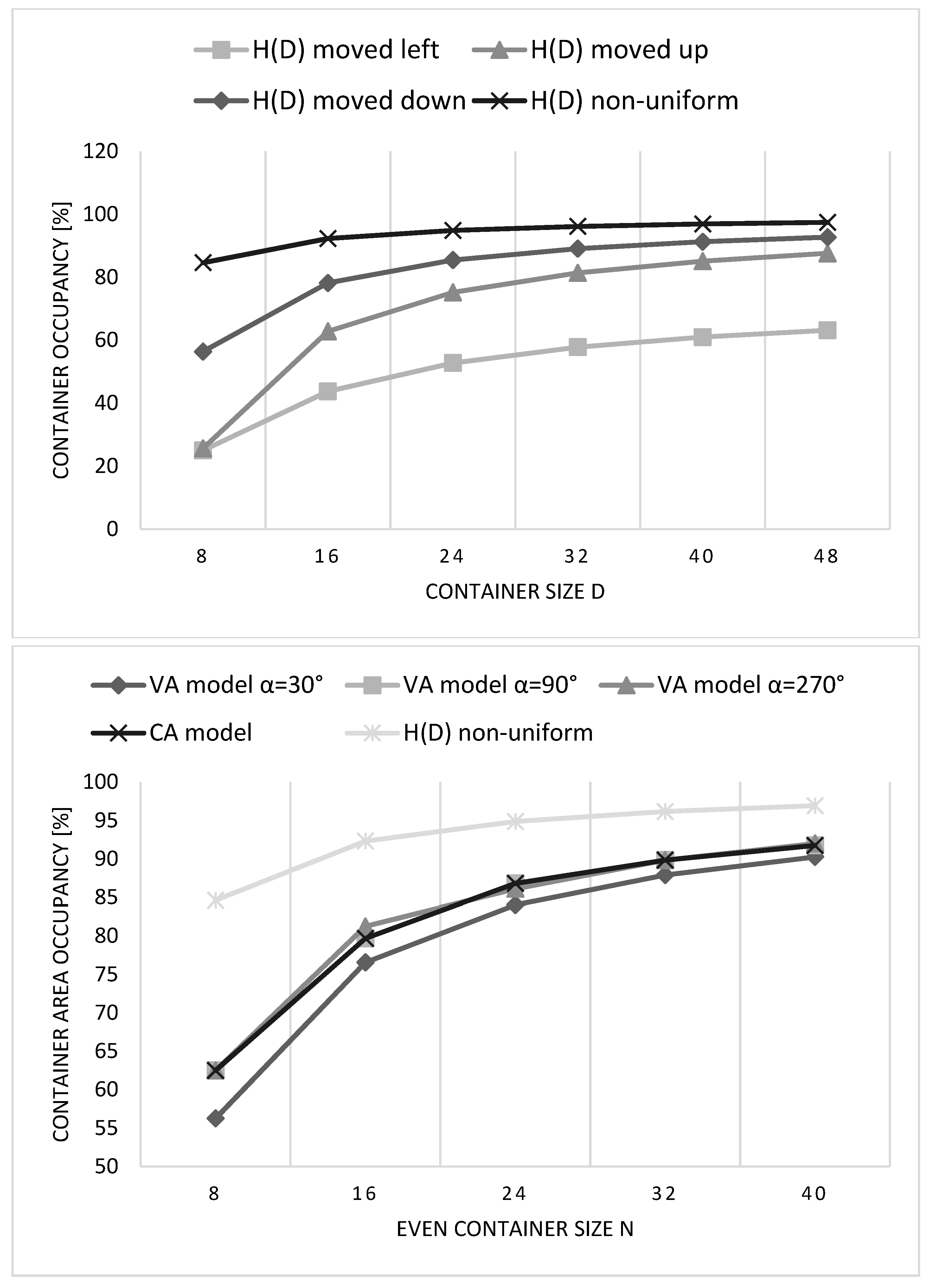
5.3. The Evaluation of the Proposed H(D) Clustering Model

To compare the proposed H ( D ) models for uniform and non-uniform clustering, we use Formula (19), Formula (21), Formula (23), Formula (25) for N f u l l and Formula (20), Formula (21), Formula (24) for N s h a r e d . The efficiency result is shown in Figure 41. We use only the default cluster orientation α = 30° for the uniform clustering models (moved left, moved down, and moved up). The maximized number of full clusters or packed items is obtained for uniform H ( D ) with the cluster plane moved down. Also, it has the lowest number of shared clusters among uniform architectures. On the other hand, H ( D ) moved left the least efficient, due to the chosen cluster angle. Namely, since sharing clusters are present at every edge of the container in H ( D ) moved left and α = 30°, it has the lowest occupancy. In order to minimize the number of shared clusters for each uniform model, we need to choose rotations α = 30°, 90°, 210° to have shared clusters only at two edges of the container and higher occupancy for architectures moved down, up and left respectively.
Compared to clustering with the existing CA and VA models, these uniform H ( D ) architectures are more efficient. Namely, in terms of shared clusters, sharing is present at each of six edges of the container with the existing models, while here clusters are shared only at some of the container edges, where sharing on two edges is the minimal solution which can be obtained. The proposed non-uniform H ( D ) model is the most efficient of all since the number of packed items in the container is maximized, and it requires no cluster sharing.
The usual goal of solving the packing problem is to minimize the void area in the container, so we define occupancy as the percentage of the container filled with polyhex clusters. It is evaluated by using the formulas for N f u l l . First, we calculate the area of the container based on total number of hexagonal cells inside ( N t o t a l = 4 N f u l l = 3 D 2 / 16 from Formula (25)), and then we calculate the number of “used” or clustered cells N c l u s t e r e d   c e l l s = 4 N f u l l based on Formula (19), Formula (21) and Formula (23). The occupancy is expressed as ratio between the two: N c l u s t e r e d   c e l l s / N t o t a l .
We can see in Figure 42 that the occupancy of the non-uniform H ( D ) container model is maximal, making it the most efficient than every other architecture. Since sharing is present at every container edge with the existing models, these shared clusters are unpacked and cause the void areas. There is no cluster sharing in the non-uniform H ( D ) structure, and all clusters are completely contained inside the container border, so the void area is minimal in this type of container. The additional enhancement is obtained with the model applied for the real CMS detector, so that container occupancy is 100% (Figure 34b).
It is to note that the efficiency of some uniform H ( D ) architectures (moved left and moved up) is less than the existing models ( 48% and 66% on average).

6. Limitations of the Study

There are a few limitations to the current study. First, clusters are assumed to be homogeneous in area and shape and composed of the same components forming the uniform cluster plane. Although several different polyhex types can be constructed, only a single cluster shape is considered in this paper, when four hexagonal cells are merged together and generating 4-hexagonal or tetrahex clusters and in our application-driven context of using “bee” tetrahex shape. We examined the cluster packing of this specific form, which is most common in engineering, and it is suitable for forming sensor “trigger cells” in CMS detector. Other polyhex structures could have also be formed and analyzed to obtain a more generic study.
Besides those general features of the current research, there are some other limitations related to specific sections in the paper. Concerning the evaluation section, for instance, when we compare the clustering with the two existing approaches (CA and VA), we consider only VA architectures moved down. This is done not to add additional complexity to the study, and one can easily derive the results for VA moved left, with cluster rotation angles 30°, 150°, and 330°. Also, when comparing the number of full and shared clusters for C A o d d and V A o d d , we consider a ring of tessellated containers with packed clusters. We took only a single ring, and one could increase the number of rings depending on the application. This can influence the conclusions from the obtained results, due to the increased number of container types with these architectures. Also, the ring configurations for VA are derived for the default case (moved down, α = 30 ° ,   90 ° ,   270 ° ), and they are not the same when cluster rotation angle is varied. Similarly, when comparing the proposed H ( D ) models, we concentrate only on the default cluster orientation α = 30°. The additional factor of the varied cluster angle rotation may influence on the obtained results.
Finally, the limitation of the proposed H ( D ) models is that the cluster area is not constant for all packed clusters, since some clusters at the container border will be smaller in the area caused by the two truncated hexagon pieces. However, this is easily prevailed with the deformed clusters at the container border, so that all inner clusters are very similar in the area. The only compromise which can be considered a limitation of the proposed H ( D ) non-uniform model is the non-uniformity of the cluster plane. Since the distance from each central cluster to NN clusters is not constant, it could slightly complicate the NN finder algorithm used in the cluster grouping procedure.

7. Conclusions

In this paper, we revisit a problem of packing symmetric “bee” tetrahex clusters in a regular hexagonal container. We start from existing container models from the literature (CA and VA). We apply these models in a new context of clustering the inner hexagonal cells in polyhex clusters and packing them in the container. We take a single ring of tessellated containers with inner packed clusters, and we formally describe the geometrical and algebraic properties by using the derived formulas. We analyze the cluster plane and derive proofs of the geometrical structures. We propose a new vertex-aligned H ( D ) model, which is more efficient than the existing approaches.
The packing efficiency is evaluated in terms of five criteria: the total number of the inner packed items (full clusters), the total number of shared clusters at the container border, the number of container types, the cluster uniformity, and whether clusters are the same in area. Since the usual goal, when solving the packing problem is to minimize the void area, we derive the container occupancy formula to evaluate the efficiency of the proposed model. The following conclusions are obtained from the study based on the desired objectives:
• Maximal number of packed items
When comparing the even C A e v e n and V A e v e n architectures (moved down, α = 30°, 90°, 270°), they are all very similar, independent on the container size. The container occupancy is, on average, 82 % , while VA (α = 30°) occupancy is the lowest with 79 % . Similarly, all the existing odd architectures C A o d d and V A o d d are almost the same, with the average occupancy in a single ring 78 % . Concerning the proposed H ( D ) models (α = 30°), H ( D ) moved down is the best, having the average packed area 13 % and 32 % larger than the moved up and the moved left architectures, respectively. It is on average 3 % better than the existing models. H ( D ) architecture moved left the least efficient, with occupancy 50 % . The proposed non-uniform H ( D ) is the most efficient, with the maximized packed area inside the container (the occupancy is 93.7 % on average).
• Minimal number of shared clusters
The existing architectures have larger cluster sharing at the container border, i.e., sharing is present on each of the six container edges, which increases the non-used or void container space. These shared clusters only take place in the container and prevent us from packing the whole cluster inside the container border. The importance of the proposed H ( D ) models is that their efficiency higher. For example, with the uniform H ( D ) models, we can obtain reduced cluster sharing on only two container edges. Hence, communication is reduced between boards that are processing data from each of the neighboring containers separately. This is important in the real CMS detector design so that a single sensor module (hexagonal container) has all “trigger cells” (tetrahex clusters) packed inside. Also, the non-uniform H ( D ) is the most efficient in this sense, as it allows no cluster sharing at all, so the communication between neighboring containers is avoided. Still, voids are present in the container (the occupancy is 93.7 % , so the non-used area is 6.3 % ), and they are eliminated by deforming the border clusters, such as in the real CMS detector application.
• Single container type
The existing architectures C A e v e n and V A e v e n provide a single container type when a ring of containers with inner packed clusters is tessellated. Clustering with architectures C A o d d and V A o d d causes a larger number of different container types making them less efficient. Also, a single container type is allowed with the proposed H ( D ) architectures.
• Uniform clustering model
The uniform clustering is provided by the existing architectures CA and VA and the proposed uniform H ( D ) models. However, in the non-uniform H ( D ) model, the orientation angle of the inner clusters is not unique, as well as the distance from each central cluster to its NNs.
• All clusters identical in the area
Unlike the existing architectures, the proposed H ( D ) models do not allow all clusters to be the same in area. However, the compromise is negligible as the deformed clusters are very close in the area to a real “bee” tetrahex ( 9.1 % if the voids are allowed in the container and 1 % if the border clusters are deformed to eliminate void areas).
The clustering scheme with the proposed non-uniform H ( D ) model is the most efficient to solve the polyhex packing problem, since it prevails in four out of five evaluation criteria. Larger container occupancy is provided compared to the existing architectures, but what is more important, sharing is completely omitted at the container border. The only compromise is the non-uniformity itself, since the criteria of all clusters having the same area is easily overcome with the deformed border tetrahex clusters. Also, there are no voids in the container this way, as the resulting occupancy is 100%. All these qualities enable the direct application of our study, i.e., the proposed cluster packing scheme of “bee” tetrahex clusters that will be used to create “trigger cells” in the new CMS HGCAL detector at CERN.
Based on the references cited, we believe that our work has a number of indirect practical applications, and we provide a view of the future use of our proposed model. For example, polyhex tiling is considered useful in robotics, and using tetrahex with an objective of maximizing the area coverage is needed for a coverage path-planning technique in a self-reconfigurable floor cleaning robot. Our model can be applied for “bee” polyhex-based morphology, but if the robot movement is limited on the targeted hexagonal ROI. Since the occupancy is the largest, and there are no void areas, the maximal area coverage can be obtained. Also, our model can be used when the polygonal area is covered with wireless sensor devices that are hierarchically clustered in “bee” polyhexes to obtain the increased energy efficiency. It would be interesting to examine the position of the cluster base stations since “bee” cluster does not have the central cell in one of the centers of the contained hexagonal cells. Our model can also be extended to consider other polyhex types and container shapes. Hence, a more general study can be obtained, providing a framework for packing different types of (not necessarily regular) convex polygons.

Author Contributions

All authors contributed equally to this work. All authors have read and agreed to the published version of the manuscript.

Funding

This research received no external funding.

Conflicts of Interest

The authors declare no conflict of interest.

Abbreviations

CACenter Aligned
CERNEuropean Laboratory for Particle Physics
CMSCompact Muon Solenoid
HGCALHigh Granularity Calorimeter
LHCLarge Hadron Collider
NNNearest Neighbor
ROIRegion of Interest
VAVertex Aligned

References

  1. Romanova, T.; Pankratov, A.; Litvinchev, I.; Pankratova, Y.; Urniaieva, I. Optimized Packing Clusters of Objects in a Rectangular Container. Math. Probl. Eng. 2019, 2019, 4136430. Available online: https://www.hindawi.com/journals/mpe/2019/4136430/ (accessed on 13 December 2019). [CrossRef] [Green Version]
  2. Litvinchev, I.; Infante, L.; Ozuna, L. Packing circular-like objects in a rectangular container. Comput. Syst. Sci. Int. 2015, 54, 259–267. [Google Scholar] [CrossRef]
  3. Torres-Escobar, R.; Marmolejo-Saucedo, J.A.; Litvinchev, I.; Vasant, P. Monkey Algorithm for Packing Circles with Binary Variables. Intell. Comput. Optim. Cham. 2019, 547–559. [Google Scholar] [CrossRef]
  4. Kampas, F.J.; Castillo, I.; Pintér, J.D. Optimized ellipse packings in regular polygons. Optim. Lett. 2019, 13, 1583–1613. [Google Scholar] [CrossRef]
  5. Kampas, F.J.; Pinter, J.D.; Castillo, I. Packing Ovals in Optimized Regular Polygons. arXiv 2019, arXiv:1901.07056. [Google Scholar] [CrossRef] [Green Version]
  6. Pankratov, A.; Romanova, T.; Litvinchev, I. Packing ellipses in an optimized convex polygon. J. Glob. Optim. 2019, 75, 495–522. [Google Scholar] [CrossRef]
  7. López, C.O.; Beasley, J.E. Packing a fixed number of identical circles in a circular container with circular prohibited areas. Optim. Lett. 2019, 13, 1449–1468. [Google Scholar] [CrossRef] [Green Version]
  8. Bennell, J.; Scheithauer, G.; Stoyan, Y.; Romanova, T.; Pankratov, A. Optimal clustering of a pair of irregular objects. J. Glob. Optim. 2015, 61, 497–524. [Google Scholar] [CrossRef] [Green Version]
  9. Peralta, J.; Andretta, M.; Oliveira, J.F. Packing Circles and Irregular Polygons using Separation Lines. In Proceedings of the 7th International Conference on Operations Research and Enterprise Systems, Funchal, Portugal, 24–26 January 2018; pp. 71–77. [Google Scholar] [CrossRef]
  10. Galiev, S.; Lisafina, M. Numerical optimization method for packing regular convex polygons. Comput. Math. Math. Phys. 2016, 56, 1402–1413. [Google Scholar] [CrossRef]
  11. Prvan, M.; Ožegović, J.; Mišura, A.B. On Calculating the Packing Efficiency for Embedding Hexagonal and Dodecagonal Sensors in a Circular Container. Math. Probl. Eng. 2019, 2019, 9624751. Available online: https://www.hindawi.com/journals/mpe/2019/9624751/cta/ (accessed on 10 December 2019). [CrossRef] [Green Version]
  12. Wang, D.; Lin, L.; Xu, L. A study of subdividing hexagon-clustered WSN for power saving: Analysis and simulation. Ad Hoc Netw. 2011, 9, 1302–1311. [Google Scholar] [CrossRef]
  13. Stoyan, Y.; Yaskov, G. Packing equal circles into a circle with circular prohibited areas. Int. J. Comput. Math. 2012, 89, 1355–1369. [Google Scholar] [CrossRef]
  14. Galiev, S.I.; Lisafina, M.S. Linear models for the approximate solution of the problem of packing equal circles into a given domain. Eur. J. Oper. Res. 2013, 230, 505–514. [Google Scholar] [CrossRef]
  15. Toledo, F.M.B.; Carravilla, M.A.; Ribeiro, C.; Oliveira, J.F.; Gomes, A.M. The Dotted-Board Model: A new MIP model for nesting irregular shapes. Int. J. Prod. Econ. 2013, 145, 478–487. [Google Scholar] [CrossRef] [Green Version]
  16. Kazakov, A.L.; Lempert, A.A.; Nguyen, H.L. The Problem of the Optimal Packing of the Equal Circles for Special Non-Euclidean Metric. In International Conference on Analysis of Images, Social Networks and Texts; Springer: Berlin/Heidelberg, Germany, 2017; pp. 58–68. [Google Scholar]
  17. López, C.O.; Beasley, J.E. Packing unequal rectangles and squares in a fixed size circular container using formulation space search. arXiv 2018, arXiv:1802.07519. [Google Scholar]
  18. Ekanayake, D.B.; Ranpatidewage, M.M.; LaFountain, D.J. Optimal Packings for Filled Rings of Circles. Appl. Math. 2020, 65, 1–22. [Google Scholar] [CrossRef]
  19. Lintzmayer, C.N.; Miyazawa, F.K.; Xavier, E.C. Online Circle and Sphere Packing. arXiv 2017, arXiv:1708.08906. [Google Scholar]
  20. Coffin, S.T. The Puzzling World of Polyhedral Dissections; Oxford University Press: Oxford, UK, 1991. [Google Scholar]
  21. Parween, R.; Shi, Y.; Parasuraman, K.; Vengadesh, A.; Sivanantham, V.; Ghanta, S.; Mohan, R.E. Modeling and Analysis of hHoneycomb—A Polyhex Inspired Reconfigurable Tiling Robot. Energies 2019, 12, 2517. [Google Scholar] [CrossRef] [Green Version]
  22. Luo, J.; Zhang, W.; Su, J.; Xiang, F. Hexagonal Convolutional Neural Networks for Hexagonal Grids. IEEE Access 2019, 7, 142738–142749. [Google Scholar] [CrossRef]
  23. Uher, V.; Gajdoš, P.; Snášel, V.; Lai, Y.-C.; Radecký, M. Hierarchical Hexagonal Clustering and Indexing. Symmetry 2019, 11, 731. [Google Scholar] [CrossRef] [Green Version]
  24. Sauvan, J.-B. Concepts and design of the CMS high granularity calorimeter Level-1 trigger. J. Phys. Conf. Ser. 2017, 928, 012026. [Google Scholar] [CrossRef] [Green Version]
  25. Collaboration, C.M.S. The Phase-2 Upgrade of the CMS Endcap Calorimeter. CERN Document Server, 21 November 2017. Available online: https://cds.cern.ch/record/2293646 (accessed on 10 December 2019).
  26. Maier, A.A. Sensors for the CMS High Granularity Calorimeter. J. Instrum. 2017, 12, C06030. [Google Scholar] [CrossRef] [Green Version]
  27. Yang, W. Maximal and Minimal Polyhexes; University of Wisconsin-Madison: Madison, WI, USA, 2002. [Google Scholar]
  28. Mahdavi-Amiri, A.; Harrison, E.; Samavati, F. Hexagonal connectivity maps for Digital Earth. Int. J. Digit. Earth 2015, 8, 750–769. [Google Scholar] [CrossRef]
  29. Holub, P.; Miller, M.; Pérez-Rosés, H.; Ryan, J. Degree diameter problem on honeycomb networks. Discrete Appl. Math. 2014, 179, 139–151. [Google Scholar] [CrossRef]
  30. Tong, X.; Ben, J.; Wang, Y. A new effective Hexagonal Discrete Global Grid System: Hexagonal quad balanced structure. In Proceedings of the 2010 18th International Conference on Geoinformatics, Beijing, China, 18–20 June 2010; pp. 1–6. [Google Scholar] [CrossRef]
  31. Van de Ville, D.; Blu, T.; Unser, M.; Philips, W.; Lemahieu, I.; Van de Walle, R. Hex-Splines: A Novel Spline Family for Hexagonal Lattices. IEEE Trans. Image Process. 2004, 13, 758–772. [Google Scholar] [CrossRef]
Figure 1. Forming the 4-hexagonal clusters: bar, pistol, worm, bee, propeller, arch, wave (Adjusted from [20,21]).
Symmetry 12 00700 g001
Figure 2. Selected 4-hexagonal cluster candidates. (a) pistol with no symmetry axes; (b) bee with two symmetry axes; (c) propeller with three symmetry axes.
Symmetry 12 00700 g002
Figure 3. A cluster packing procedure. (a) Tessellation of hexagonal containers with small hexagons inside; (b) Overlap with the regular cluster grid.
Symmetry 12 00700 g003
Figure 4. The NN cluster distance and coordinates in the uniform 4-hexagonal cluster plane.
Symmetry 12 00700 g004
Figure 5. Forming 4-hexagonal clusters and their orientations.
Symmetry 12 00700 g005
Figure 6. Multi-resolution hexagonal grids. CA architecture (up) and VA architecture (down) (Adjusted from [28,30]).
Symmetry 12 00700 g006
Figure 7. The options for the clustering center in the VA architecture. (a) Clustering center in cell A; (b) Clustering center in cell B; (c) Clustering center in cell C.
Symmetry 12 00700 g007
Figure 8. R/3 and R/4 subdivisions for the CA architecture (Adjusted from [12]).
Symmetry 12 00700 g008
Figure 9. 4-hexagonal CA clustering result for even container n = 6 and cluster orientation 30°, 90°, 150°. A single container type N is shown.
Symmetry 12 00700 g009
Figure 10. 4-hexagonal CA clustering result for even container size and cluster orientation 30°.
Symmetry 12 00700 g010
Figure 11. CA container example and the corresponding path.
Symmetry 12 00700 g011
Figure 12. The two adjacent clusters in C A odd architecture.
Symmetry 12 00700 g012
Figure 13. 4-hexagonal CA clustering result for odd container n = 7 and cluster orientation 30°, 90°, 150°. Two container types N and M are shown.
Symmetry 12 00700 g013
Figure 14. 4-hexagonal CA clustering result for odd container size and cluster orientation 30°.
Symmetry 12 00700 g014
Figure 15. R/3 and R/4 subdivisions for VA architecture.
Symmetry 12 00700 g015
Figure 16. 4-hexagonal VA clustering result for even container n = 6 and cluster orientation 30°, 90°, 270°. A single container type N is shown (central cluster position down).
Symmetry 12 00700 g016
Figure 17. 4-hexagonal VA clustering result for even container n = 6 and cluster orientation 30°, 150°, 330°. A single container type N is shown (central cluster position left).
Symmetry 12 00700 g017
Figure 18. 4-hexagonal VA clustering result for even container size and cluster orientation 30° (central cluster position down).
Symmetry 12 00700 g018
Figure 19. 4-hexagonal VA clustering result for even container size and cluster orientation 30° (central cluster position left).
Symmetry 12 00700 g019
Figure 20. 4-hexagonal VA clustering result for odd container n = 7 and cluster orientation 30°, 90°, 270°. Three container types N, M, and E are shown (central cluster position down).
Symmetry 12 00700 g020
Figure 21. 4-hexagonal VA clustering result for odd container n = 7 and cluster orientation 30°, 150°, 330°. Three container types N, M, and E are shown (central cluster position left).
Symmetry 12 00700 g021aSymmetry 12 00700 g021b
Figure 22. 4-hexagonal VA clustering result for odd container size and cluster orientation 30° (central cluster position down).
Symmetry 12 00700 g022
Figure 23. 4-hexagonal VA clustering result for odd container size and cluster orientation 30° (central cluster position left).
Symmetry 12 00700 g023
Figure 24. The proposed container structures. (a) container model H ( 8 ) with marked edges; (b) the tessellation of containers (Adjusted from [29]).
Symmetry 12 00700 g024
Figure 25. Center of clustering positions. (a) down; (b) left; (c) up.
Symmetry 12 00700 g025
Figure 26. The comparison of cluster area for CA, VA, and the proposed model.
Symmetry 12 00700 g026
Figure 27. (a) Container column; (b) Containers in adjacent column.
Symmetry 12 00700 g027
Figure 28. 4-hexagonal H ( D ) clustering result for container size D = 16 and cluster orientation 30° and 90°. A single container type is shown (central cluster position down).
Symmetry 12 00700 g028
Figure 29. 4-hexagonal H ( D ) clustering result for container size D = 16 and cluster orientation 30°, 90°, and 210°. Single container type is shown (central cluster position left).
Symmetry 12 00700 g029
Figure 30. 4-hexagonal H ( D ) clustering result for container size D = 16 and cluster orientation 30°, 90°, and 270°. Single container type is shown (central cluster position up).
Symmetry 12 00700 g030
Figure 31. 4-hexagonal H ( D ) clustering result for container size D = { 8 ,   16 ,   24 } and cluster orientation 30° (central cluster position down).
Symmetry 12 00700 g031
Figure 32. 4-hexagonal H ( D ) clustering result for container size D = {8, 16, 24} and cluster orientation 30° (central cluster position left).
Symmetry 12 00700 g032
Figure 33. 4-hexagonal H ( D ) clustering result for container size D = { 8 ,   16 ,   24 } and cluster orientation 30° (central cluster position up).
Symmetry 12 00700 g033
Figure 34. The proposed non-uniform clustering. (a) The model with void areas. The cluster NN distances d 1 , d 2 , and d 3 are shown; (b) The model without void areas (used in the CMS detector).
Symmetry 12 00700 g034
Figure 35. 4-hexagonal H(D) clustering result in 120° cluster plane for D = {8, 16, 24}.
Symmetry 12 00700 g035
Figure 36. The number of full clusters compared for CA and VA even models.
Symmetry 12 00700 g036
Figure 37. The number of shared clusters compared for CA and VA even models.
Symmetry 12 00700 g037aSymmetry 12 00700 g037b
Figure 38. Clustering configurations in a single ring of container tessellation. (a) 3 N + 4 M ; (b) 3 N + 2 M + 2 E ; (c) N + 2 M + 4 E .
Symmetry 12 00700 g038
Figure 39. The number of full clusters compared for CA and VA odd models.
Symmetry 12 00700 g039
Figure 40. The number of shared clusters compared for CA and VA odd models.
Symmetry 12 00700 g040aSymmetry 12 00700 g040b
Figure 41. The number of full and shared clusters compared for the proposed H ( D ) models.
Symmetry 12 00700 g041aSymmetry 12 00700 g041b
Figure 42. The container occupancy comparison between H ( D ) models and comparison with the existing VA and CA architectures.
Symmetry 12 00700 g042
Table 1. Even container size in the 4-hexagonal CA clustering model.
Container Size (n)#Full (Inner) Clusters#Border (Shared) Clusters
6510
81013
101717
122720
143823
165127
Table 2. Odd container size in the 4-hexagonal CA clustering model.
Container Size (n)#Full (Inner) Clusters#Border (Shared) Clusters
N f u l l M f u l l N s h a r e d M s h a r e d
53299
7671311
912141815
1121212119
1330322521
1542453025
Table 3. Even container size in the 4-hexagonal VA clustering model.
Container Size (n)#Full (Inner) Clusters#Border (Shared) Clusters
6411
8915
101620
122523
143627
164932
Table 4. The cluster rotation invariance for V A e v e n architectures.
V A e v e n   Moved   Down V A e v e n   Moved   Left
N f u l l , N s h a r e d N f u l l , N s h a r e d
α = 30°Formula (10), (11)Formula (10), (11)
α = 90°Formula (1), (4)Formula (10), (11)
α = 270°Formula (12), (9)Formula (10), (11)
α = 150°Formula (10), (11)Formula (12), (9)
α = 330°Formula (10), (11)Formula (1), (4)
Table 5. Odd container size in the 4-hexagonal VA clustering model.
Container Size (n)#Full (Inner) Clusters#Border (Shared) Clusters
N f u l l M f u l l E f u l l N s h a r e d M s h a r e d E s h a r e d
53138109
7776121215
9131312151816
11221921182221
13323130222427
15444342253028
Table 6. The cluster rotation invariance for V A o d d architectures.
V A o d d   Moved   Down V A o d d   Moved   Left
N f u l l , M f u l l , E f u l l , N s h a r e d , M s h a r e d , E s h a r e d N f u l l , M f u l l , E f u l l , N s h a r e d , M s h a r e d , E s h a r e d
α = 30°Formula (14), (15), (6), (16), (17), (18)Formula (6), (15), (14), (18), (17), (16)
α = 90°Formula (15), (6), (14), (17), (18), (16)Formula (6), (15), (14), (18), (17), (16)
α = 270°Formula (6), (15), (14), (18), (17), (16)Formula (6), (15), (14), (18), (17), (16)
α = 150°Formula (14), (15), (6), (16), (17), (18)Formula (6), (15), (14), (18), (17), (16)
α = 330°Formula (14), (15), (6), (16), (17), (18)Formula (15), (6), (14), (17), (18), (16)
Table 7. The proposed 4-hexagonal H ( D ) clustering model.
Container Size (D)#Full (Inner) Clusters#Border (Shared) Clusters
822
16104
24246
32448
407010
Table 8. The proposed 4-hexagonal H ( D ) clustering model.
Container Size (D)#Full (Inner) Clusters#Border (Shared) Clusters
816
16712
241918
323724
406130
Table 9. The proposed 4-hexagonal H ( D ) clustering model.
Container Size (D)#Full (Inner) Clusters#Border (Shared) Clusters
814
1688
242112
324016
406520
Table 10. The cluster rotation invariance for H ( D ) architectures.
H ( D )   Moved   Down H ( D )   Moved   Left H ( D )   Moved   Up
N f u l l , N s h a r e d N f u l l , N s h a r e d N f u l l , N s h a r e d
α = 30°Formula (19), (20)Formula (21), (22)Formula (23), (24)
α = 90°Formula (21), (22)Formula (23), (24)Formula (19), (20)
α = 210°Formula (21), (22)Formula (19), (20)Formula (19), (20)
α = 270°Formula (19), (20)Formula (23), (24)Formula (21), (22)
Table 11. The proposed 4-hexagonal H ( D ) clustering model.
Container Size (D)#Full (Inner) Clusters#Border (Shared) Clusters
830
16120
24270
32480
40750
481080
Table 12. The summary of the presented models.
Model Sub-TypeSub-ClassesCenter PositionOrientationsChosen Model
CA
( n = 3 k + r )
C A e v e n
( n = 2 k )
C A e v e n ( 0 ) - no movements needed α = 30 ° , 90 ° ,   150 ° α = 30 °
C A e v e n ( 1 )
C A e v e n ( 2 )
C A o d d
( n = 2 k + 1 )
C A o d d ( 0 ) - no movements needed α = 30 ° , 90 ° ,   150 ° α = 30 °
C A o d d ( 1 )
C A o d d ( 2 )
VA
( n = 3 k + r )
V A e v e n
( n = 2 k )
V A e v e n ( 0 ) - moved down
- moved left
α = 30 ° , 90 ° ,   150 ° , 270 ° ,   330 ° - moved down
α = 30 ° , 90 ° ,   270 °
V A e v e n ( 1 )
V A e v e n ( 2 )
V A o d d
( n = 2 k + 1 )
V A o d d ( 0 ) - moved down
- moved left
α = 30 ° , 90 ° ,   150 ° , 270 ° ,   330 ° - moved down
α = 30 ° , 90 ° ,   270 °
V A o d d ( 1 )
V A o d d ( 2 )
H ( D )
( D = 8 k )
uniform - moved down
- moved left
- moved up
α = 30 ° , 90 ° ,   210 ° , 270 ° - all positions
α = 30 °
non-uniform- with voids
- no voids

