Article

Experimental and Numerical Investigation on Bearing Capacity of Circumferential Joint of New Spatial Steel Tubular Grid Arch in Mined Tunnel

1
Key Laboratory of Urban Underground Engineering of Ministry of Education, Beijing Jiaotong University, Beijing 100044, China
2
School of Civil Engineering, Beijing Jiaotong University, Beijing 100044, China
3
China Railway 11th Bureau Group Co., Ltd., Wuhan 430000, China
4
China Railway 11th Bureau Group 4th Engineering Co., Ltd., Wuhan 430074, China
*
Author to whom correspondence should be addressed.
Symmetry 2020, 12(12), 2065; https://doi.org/10.3390/sym12122065
Submission received: 24 November 2020 / Revised: 8 December 2020 / Accepted: 10 December 2020 / Published: 12 December 2020

Abstract

:
Under the circumstance of soft fractured surrounding rock with high geo-stress, the support technology of tunnel has become a major challenge. Traditional I-shaped steel and bar lattice girder, which cross-sections are often designed to be left-right symmetrical, may have insufficient strength and stiffness. Based on the concept of symmetry, a new support technology of spatial steel tubular grid (SSTG) arch is designed with high strength and large stiffness. In order to clarify the mechanical properties and failure mechanism of SSTG arch used as primary support, through laboratory and numerical experiments, this paper carries out the bending tests for the circumferential joint of SSTG arch components combined with the excavation tunnel project of Panyu Square Station in Guangzhou, and the analyses of the ultimate bearing capacity, deflection displacement, failure modes, and stress–strain evolution laws of joint components are conducted in detail. The results show that during the whole process of loading, the arch components have experienced elastic growth stage, plastic development stage, and final failure stage. The average ultimate bending capacity of SSTG arches is 340.5 kN·m, and the joint opening is 13.9 mm. The joint form of high-strength bolt + rigid flange plate proposed in the paper has reasonable stress state and high safety redundancy, which can bear the load of surrounding rock effectively, and ensure the safety in tunnel construction. The research results could provide a theoretical basis for the design and application of SSTG arch support in related projects.

1. Introduction

In recent years, with the rapid development of China’s transportation construction, the traffic tunnel construction is developing to the direction of large scale and deep buried. It is inevitable to face weak surrounding rock with high geo-stress and severe geological environment. Affected by the factors of high geo-stress and large deformation, many tunnels under construction or already built have suffered large deformation disasters [1,2], such as anchor rod breakage, steel arch distortion, and sprayed concrete cracking. The collapse leads to frequent repairs, increase support costs and decrease construction efficiency, and has become a scientific problem that affects the safety of the underground engineering construction.
In view of the problems of insufficient primary support capacity and large deformation in the complex surrounding rock tunnel, it is possible to reasonably strengthen the initial support structure of the tunnel. Domestic and foreign scholars have done a lot of research on the optimization design of primary support, the mechanical characteristics of composite support structure considering shotcrete, and the influence on support effect. First, a new type of three limb grid steel frame with 8-shaped reinforcement was first designed in Germany [3], and the rationality and applicability of the structure design were proved by practical engineering application. On this basis, some researchers had carried out the structural parameter optimization, and obtained the deformation characteristics, ultimate bearing capacity, and failure mode of different forms of grid arch through the mechanical performance test of bending load [4,5,6]. Moreover, In order to evaluate the relationship between the ultimate bearing capacity and the cost of each component, a series of optimization studies were carried out by introducing performance index parameters [7]. Comparing with the traditional lattice girder, I-steel concrete structure was more suitable for surrounding rock conditions with large deformation rate in early stage [8], and heat-treated high-strength lattice girder had certain advantages in mechanical properties and applicability [9,10]. Bolt support technology is more widely used in tunnel engineering and has achieved good application effects. In the process of tunnel construction, various weak surrounding rocks are often encountered, and engineering technicians and scholars have conducted a lot of experiments and researches on the role of bolts in soft rocks [11,12,13,14]. Recently, steel tube confined concrete structures are more and more widely used in tunnel support, and they have obvious advantages in compressive strength, flexural performance, and bearing capacity. A new type of steel grid concrete core tube support structure system was independently developed, and achieved good application effect [15]. In addition, considering the obvious limitations of bolt-mesh-shotcrete support in high geo-stress soft rock tunnel [16,17], several new high-strength steel tube confined concrete arch support systems were proposed, such as UCC arch, CCFST arch, and SCFST arch, which were successfully applied to the field test, and forming a tunnel assembly confined concrete construction system [18,19,20,21,22,23,24,25].
Nevertheless, in the face of some deep buried and high geo-stress problems, the bearing capacity of the support is still insufficient. Therefore, based on the design concept of “strong support, immediate support,” a new spatial steel tubular grid (SSTG) arch is designed, which takes high-strength seamless steel tube as the main bearing component, high-strength π-shaped reinforcement + U-shaped reinforcement as connecting reinforcement, and trapezoidal flange plate + high-strength bolt as joint connection form. The specific structure and joint connection are shown in Figure 1.
At present, the research on this type of SSTG arch used in tunnel engineering is still lack of systematic research, in order to understand the mechanical properties and failure mechanisms of SSTG arch, the flexural stiffness and yield strength of joint components should be determined at first. Therefore, this paper through laboratory and numerical experiments, carries out the bending tests for the circumferential joint of SSTG arch, hoping to provide a theoretical reference for the design of the circumferential joint and the practical application of SSTG arch support in related projects. The main research contents and technical route are shown in Figure 2. In order to realize rapid installation and timely seal the surrounding rock, the arch assembly machine is developed, and field application of the new SSTG arch was successfully carried out in the underground tunnel of Guangzhou Panyu Square Station.

2. Engineering Background

The project is an underground tunnel between Hengli and Panyu Square Station of Guangzhou rail transit line 22, which is located in Panyu District, Guangzhou. The underground tunnel passes through Luojia River, Dongxing Road, Square East Road to Panyu Square Station, and the direction is generally North-South. The tunnel is a single-hole double-line tunnel, belonging to class III–IV surrounding rock. The thickness of overburden soil is 26.4~26.9 m, which is mainly composed of muddy soil, muddy medium coarse sand, and sandy clay. The excavation section span is 14.7 m, the height is 11.95 m, and the cross-section area is 143 m2. The bench method is adopted for construction. The geographical location of interval tunnel is shown in Figure 3.
The original design plan adopts the H264 bar lattice girder as the initial support form. Taking into account the insufficient bearing capacity and the impact of the construction period, it is decided to adopt the combined support technology of the SSTG arch + rock bolts + shotcrete to ensure the tunnel construction safety. The assembly of the arch in the tunnel is shown in Figure 4.

3. Experimental Testing

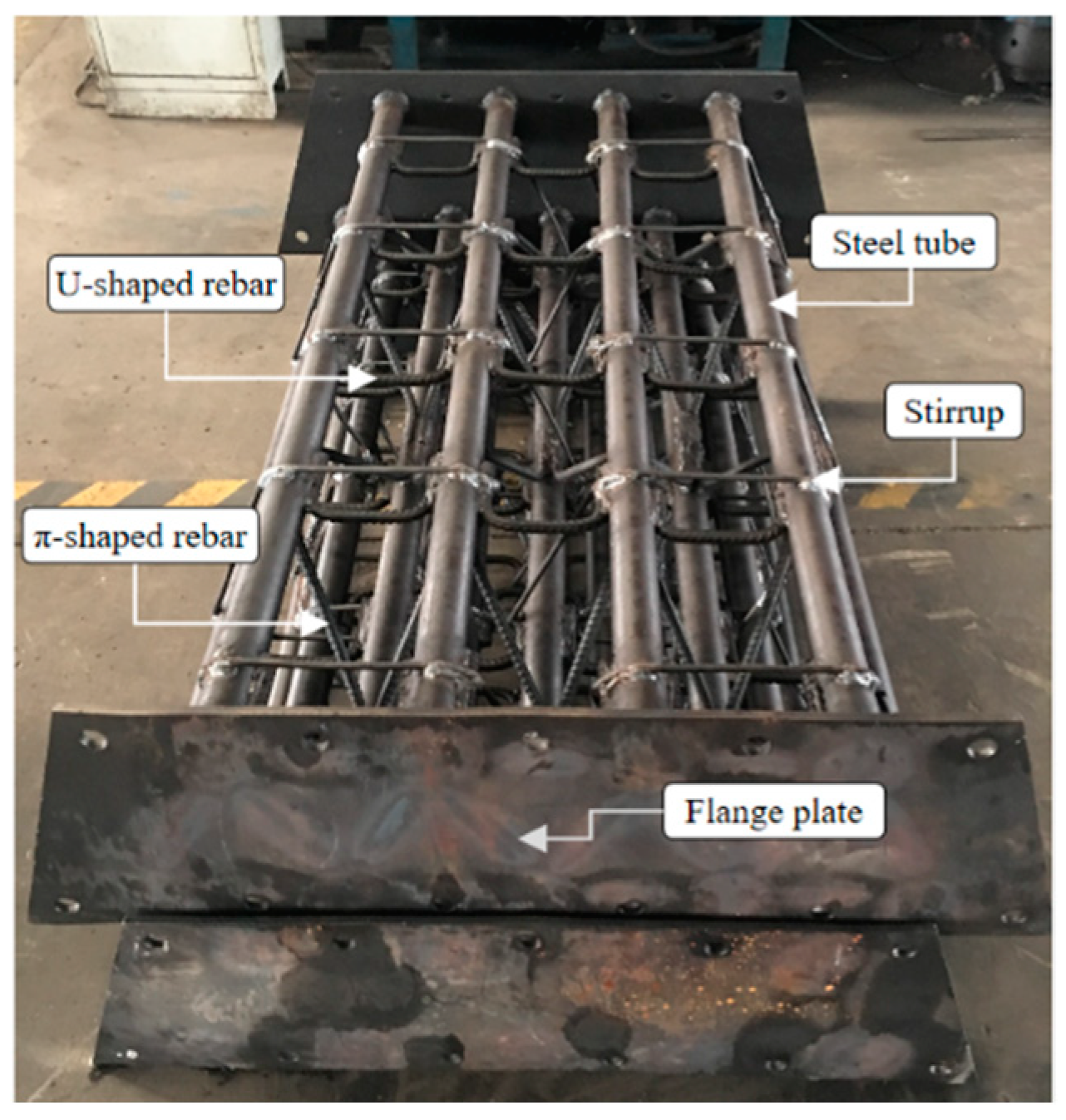
3.1. Specimen Design and Test Condition

The design of the specimen is based on the underground tunnel project of Panyu Square Station of Guangzhou Metro, and combined with the relevant stratum condition and construction technology. Three groups of SSTG arches are used in the experiment. In order to simplify the test and calculation, the test adopts straight joint instead of arch joint, as expressed in Figure 5. The length of the tested specimens is 1500 mm, the maximum width is 1109 mm, the center thickness is 220 mm, the diameter of the π-shaped and U-shaped connecting ribs are both 14 mm, and the thickness of the flange plate is 10 mm. The joints are connected by bolts, and the steel tubes were welded to the flange plate to form a whole, and U-shaped rebar is also welded to improve the stiffness and bearing capacity. The outer ring and inner ring of main limb steel tubes adopt Q420 seamless steel tube with a diameter of 50 mm [26], a wall thickness of 8 mm, which are staggered at equal intervals along the tunnel direction to form the main force-bearing framework of the structure. The outer ring of steel tubes adopts the 4-leg type, and the inner ring adopts the 5-leg type, respectively equipped with M20 high-strength bolts of 10.9 grades for connection [27]. Each steel tube is connected and fixed by HRB400 connecting rebar to form a stable structure of positive triangle and inverted triangle, which is beneficial to improve the flexural stiffness of SSTG arch and limit the radial displacement. The section structure is shown in Figure 6, and the physical and mechanical parameters of the specimens are displayed in Table 1.
This paper takes the stratum condition of Guangzhou Panyu Square Station as the design basis. The groundwater level is −1.8 m, the tunnel depth is 26.7 m, the tunnel passes through moderately weathered to slightly weathered granite, and the uniaxial natural ultimate compressive strength is 36 MPa~59.3 MPa. It is calculated that the maximum positive bending moment of SSTG arch is about 200 kN·m, and the axial force was about 640 kN. The experiment conditions are shown in Table 2.

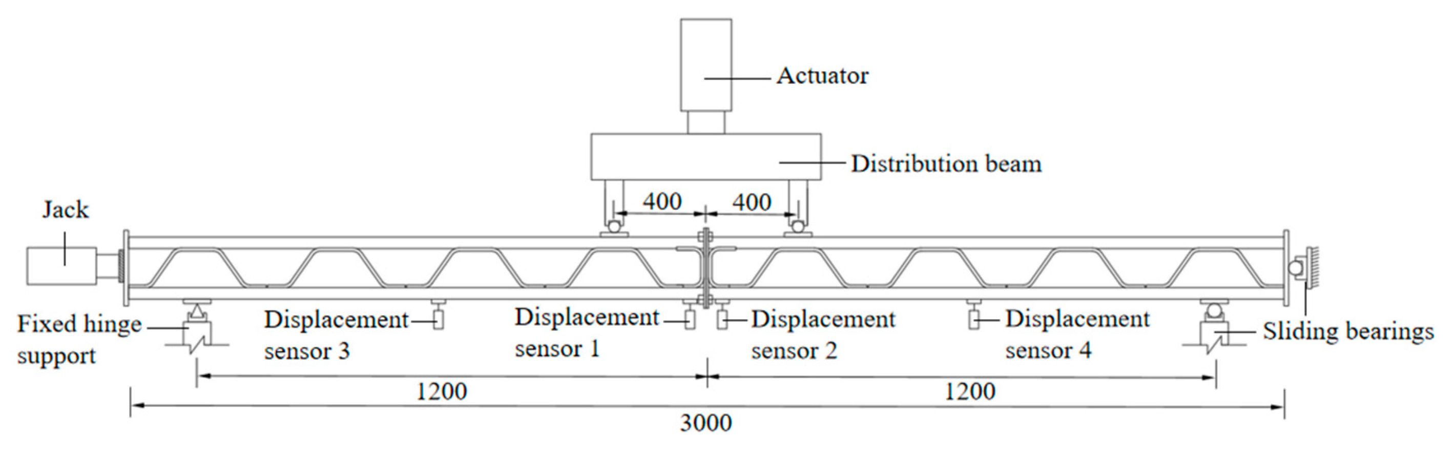
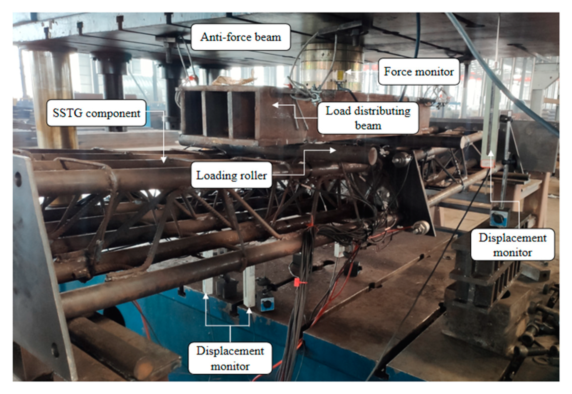
3.2. Test Equipments and Loading Scheme

The specimens are tested on the hydraulic loading system. The vertical load consists of two 2500 kN actuators, which can provide a maximum vertical loading capacity of 5000 kN. The horizontal load consists of a 2000 kN actuator, which can provide a maximum horizontal loading capacity of 2000 kN. The horizontal actuator of the loading system provides a horizontal load to the specimen to simulate the axial force, and the vertical actuators supply a vertical load to replace the bending moment at the joint. The force diagram is displayed in Figure 7.
The high-speed static resistance strain data acquisition and analysis system is used to collect data on the deformation, strain, and bolt axial force of the specimens in real time, and the vertical load is recorded by the JMZX-3006 comprehensive tester. Before the test, the geometric and physical alignment of the specimens is carried out. The test loading is divided into two steps: first, loading the horizontal force to the set value, then loading the vertical force. The pressure holding by steps is realized through loading sub-system. The loading rate is set as 2.0 kN/s, and the pressure is held for 4 min per 20 kN. When the load does not increase significantly, it is changed to displacement loading at a loading rate of 0.2 mm/s until the entire arches enter into their yield state or significant damages occurred. Figure 8 shows the loading in progress.

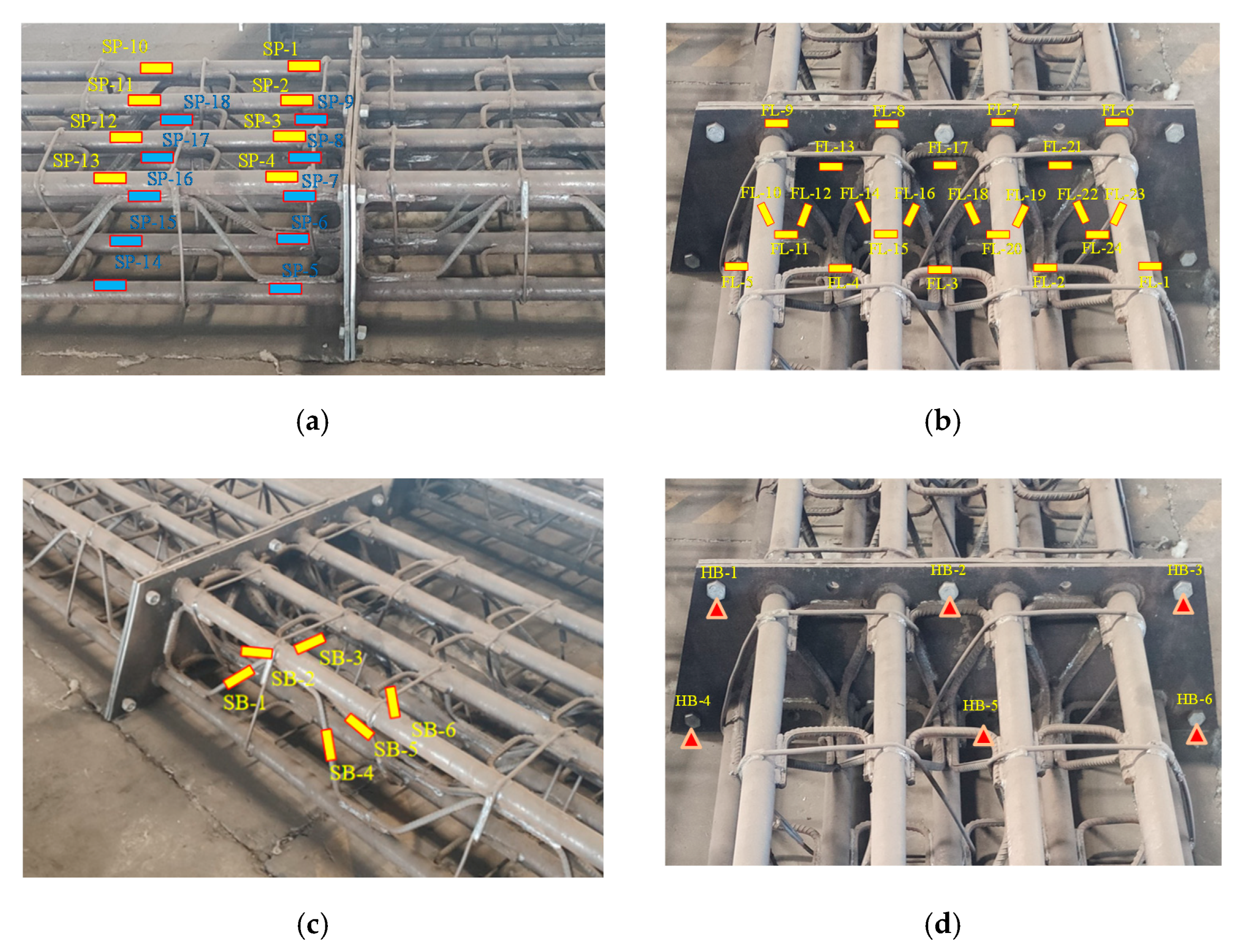
3.3. Monitoring Scheme

As shown in Figure 7 and Figure 9, the measuring points are mainly distributed in the following five areas: first, on the tension and compression sides, the stress and strain evolution law of the steel tubes during the loading process is monitored respectively, and the measuring points are numbered with SP; second, the measuring points are arranged at a position where the flange plate is prone to distortion, and numbered with FL; third, the measuring points are arranged on the π-shaped connecting bars to monitor the strain, and named with SB; fourth, in order to study the working performance of bolts at different positions, the JTM-Y1800 pressure sensors are used to measure the stress status of the bolts, and numbered with HB; fifth, at the mid-span position of the joint, displacement meters with a measuring range of 100 mm are arranged to monitor the vertical deformation.
The measurement items in the bending test included: the surface strain of the main limb steel tubes on the tension and compression side, the strain of the flange plate, the joint opening, the strain of the π-shaped connecting rebar, the axial force of the bolt, the mid-span deflection, etc. All measuring points are summarized in Table 3.

4. Results and Discussion

4.1. Experiment Phenomenons

The SSTG arches present a failure mode of combination of compression and bending. Under the action of the bending moment, the flange plates on the tension side exhibit obvious opening deformation, and there is a gap between the flange plates, forming a cavity, but there is no obvious opening deformation on the compression side of the joint. In addition, the deformation of steel tubes on the tension side is relatively larger, and there is a certain degree of necking phenomenon. During the entire loading process, the π-shaped ribs have obvious bending deformation, and emerge breakage occasionally near the bearing position. Moreover, the stirrups also produce obvious irregular deformation along with the uneven deformation of the steel tubes. After the loading is completed, it is observed that the bolts are in good condition without bending deformation and anchorage failure. The initial and final failure modes of SSTG arches are shown in Figure 10.

4.2. Deflection Displacement

In the flexural loading test of SSTG arches, the vertical downward displacement of the joint is recorded as the mid-span deflection, and the value is positive. The vertical load collected by the pressure sensor is converted into the bending moment of circumferential joint. Under the combined action of horizontal axial compression and bending moment, the bending moment–mid-span deflection curve of SSTG arch is shown in Figure 11.
The deformation of the SSTG arches is divided into the following three stages during the loading process:
(1)
When the bending moment is 0~180 kN·m, the curve increases linearly, and the maximum mid-span deflection is about 16.7 mm; the SSTG arches have no obvious deformation except for local small deformation.
(2)
When the bending moment is within the range of 180~300 kN·m, the curve shows approximately linear development, and the deflection growth rate gradually accelerates. At this time, mid-span deflection reaches 34.9 mm, and SSTG arches have a certain degree of bending deformation.
(3)
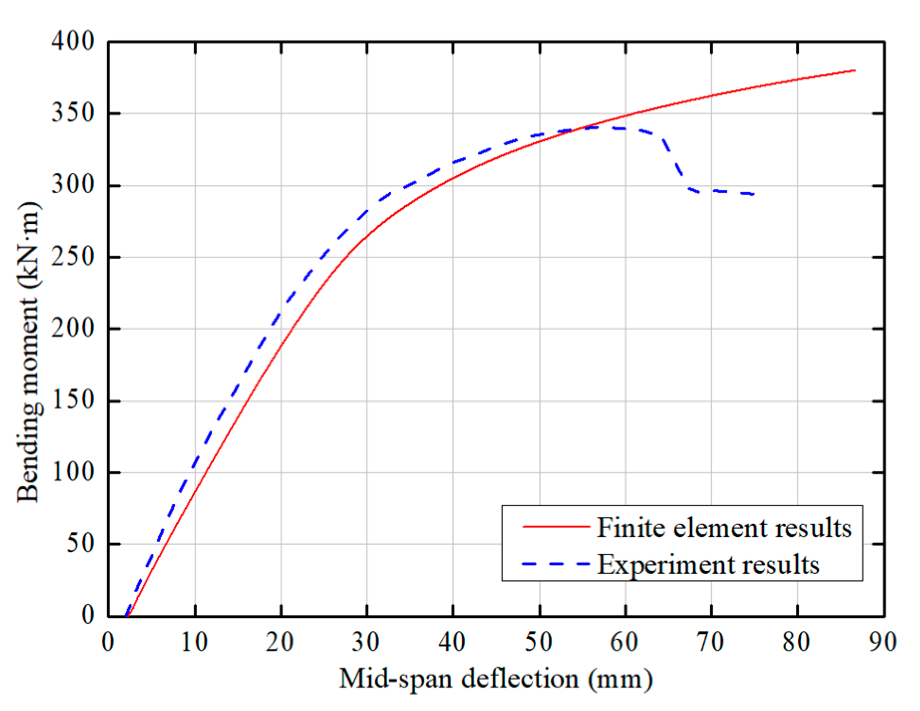
After the bending moment exceeds 300 kN·m, the deflection growth rate is further accelerated. When the bending moment reaches 340.5 kN·m, the deflection is 56.7 mm; reaching the ultimate bearing capacity, the SSTG arches fail to resist external load, and show a rapid growth of mid-span deflection.
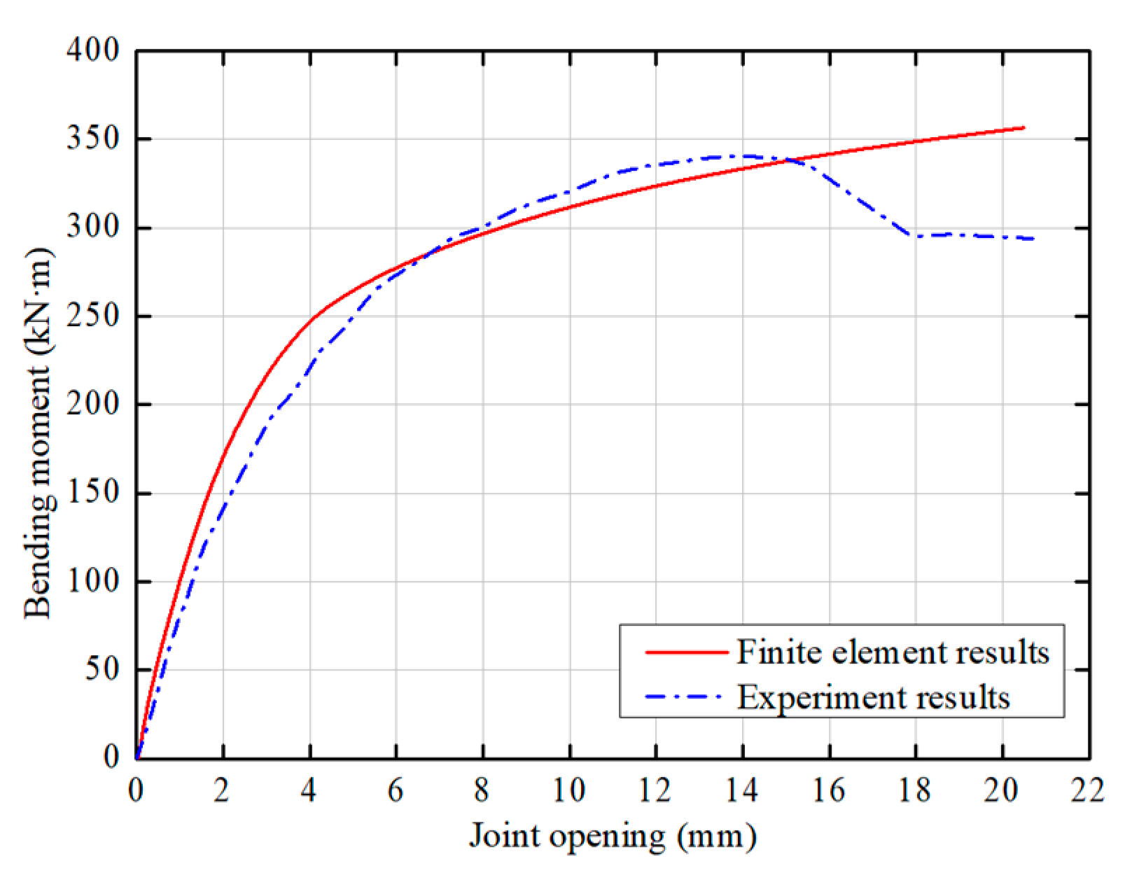
4.3. Joint Opening

The deformation of the flange plates is another important index for evaluating the bearing performance of the joint. According to the analysis of the deformation of the flange plates on the tension side, the bending moment–joint opening curve is obtained, which is similar to the bending moment–mid-span deflection curve and also experiences the elastic growth stage, the plastic development stage and the final failure stage.
(1)
It can be seen from Figure 12 that at the initial stage of loading, the opening value of the joint increases slowly with the bending moment, and the maximum opening is about 3.0 mm.
(2)
When the load continues to be applied, the joint opening rate increases and the stiffness of the specimens decreases gradually, the maximum joint opening amount reaches 8.0 mm.
(3)
With the joint opening increasing rapidly, the vertical load improves further until the specimens reach the ultimate bearing capacity and lose the ability to resist deformation. When the ultimate bearing capacity is 340.5 kN·m, the joint opening deformation reaches 13.9 mm.
In combination with Table 1, it can be seen that the design value of the joint of SSTG arches under the positive bending moment is 200 kN·m, which does not reach the yield load of 298 kN·m. Therefore, the joint design of the SSTG arches can be considered safe and reasonable.

4.4. Steel Tube Strain

The relationship between the bending moment and the strain of the steel tubes is shown in Figure 13. A total of 18 strain measurement points are monitored for two sections. For Section 1, adjacent to the joint, the maximum tensile strain occurs at the measuring point of SP-7 with the strain value of 4643 × 10−6, and the ultimate compressive strain on the tensile side was −1081 × 10−6. For Section 2, the maximum tensile strain occurred at the measuring point of SP-15 with the strain value of 1634 × 10−6, and the ultimate compressive strain on the tension side is −2061 × 10−6 which occurred at the measuring point of SP-13 of the main limb steel tube.

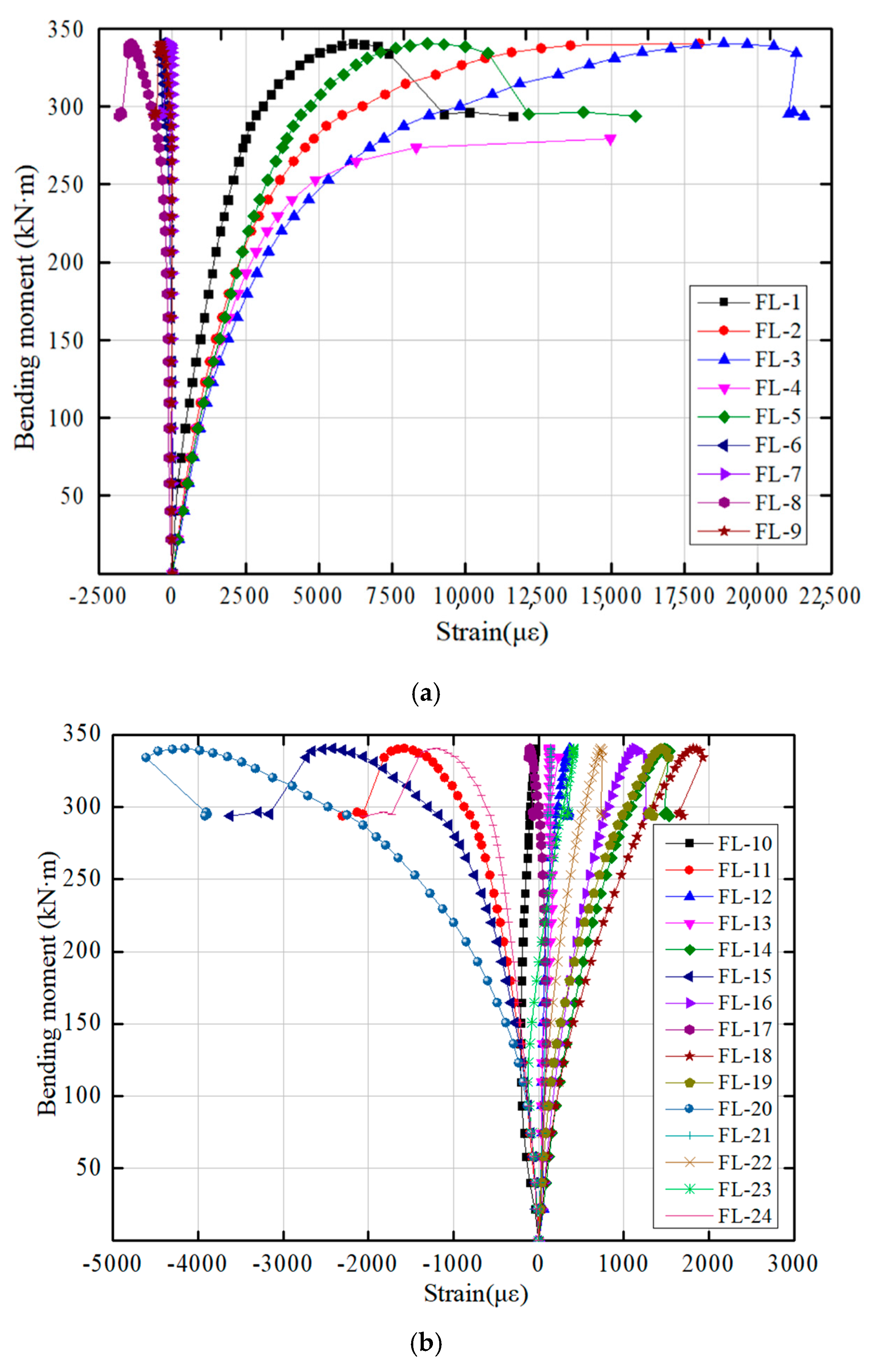
4.5. Flange Plate Strain

The relationship between the bending moment and the strain of the flange plate is shown in Figure 14. There are nine strain-measuring points on the periphery of the flange plate and 15 strain-measuring points on the inside.
It can be seen from Figure 13a that the ultimate strain values range of the measuring points of FL-1~FL-5 on the tension side is 11,638 × 10−6~21,577 × 10−6, and the maximum tensile strain occurs at the measuring point of FL-3. The range of ultimate strain values of measuring points of FL-6~FL-9 on the compression side is −373 × 10−6~−1826 × 10−6, and the maximum compressive strain occurs at measuring point of FL-8. It can be seen from Figure 13b that among the measuring points of FL-10~FL-24, the maximum tensile strain occurs at the measuring point of FL-18 with the value of 1931 × 10−6. The maximum compressive strain occurs at measuring point of FL-20, and the ultimate strain value is 4613 × 10−6.
In summary, the flange plate on the tension side bears greater tensile stress, which is consistent with the opening deformation of the flange plates. While the flange plate on the compression side bears smaller compressive stress. The inner area of the flange plate is mainly in tensile stress state, while there is large compressive stress locally.

4.6. Rebar Strain

The relationship of bending moment–rebar strain is displayed in Figure 15. A total of six strain measuring points for 2 sections are monitored, and the strain gauges are pasted on the reinforcement surface after grinding. As shown in Figure 9, the measuring points of SB-1~SB-3 are located on the same cross-section, and the strain value range is 1703 × 10−6~−1926 × 10−6. The maximum tensile strain occurs at the measuring point of SB-1, the maximum compressive strain occurs at the measuring point of SB-2. It can be seen that the different positions of the measuring points, the force modes also change accordingly. The measuring points of SB-4~SB-6 are located on the other section, and the strain value range is −246 × 10−6~−1595 × 10−6, all of which bear compressive stress, and the maximum compressive strain occurs at measuring point of SB-5.

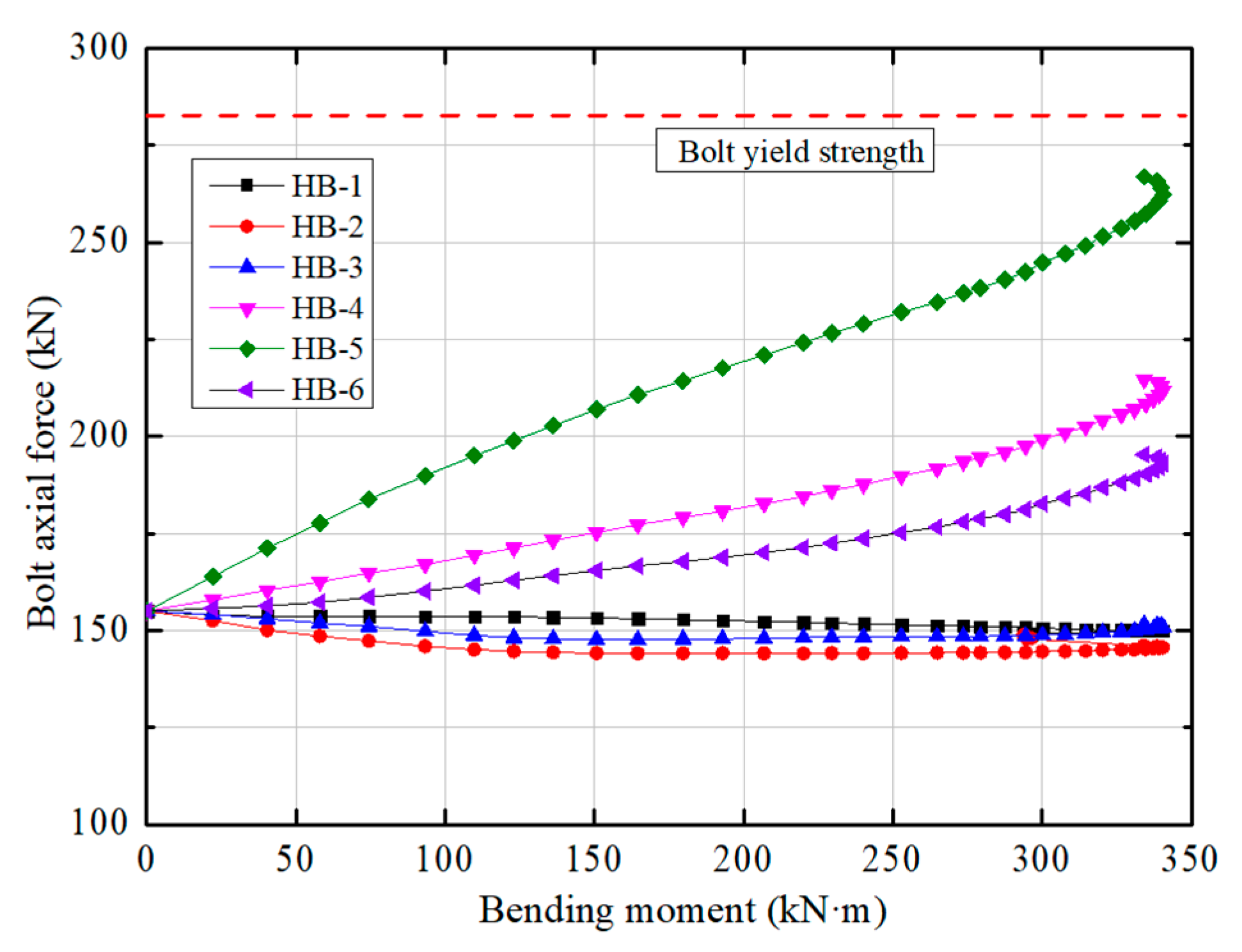
4.7. Bolt Axial Force

The relationship between bending moment and bolt axial force is shown in Figure 16. Six axial force meters are arranged to monitor the stress of the bolts on the tension side and compression side.
According to Figure 16, during the whole loading process, the bolt axial force of measuring points of HB-1~HB-3 located on the compression side, reduced by 3.9%, 6.5%, and 3.6% respectively compared with the initial preload. For measuring points of HB-4~HB-6, the bolt axial force increases faster during the entire loading process, and measuring point of HB-5 is the most obvious, which is about 70.3% higher than the initial preload. HB-4 and HB-6 measuring points, increased by 38.2% and 29.1% sequentially compared with the initial preload. All of them are within the scope of safety design.
Based on the above analysis, the bolts on the compression side have good stress condition and a high safety factor. The bolts on the tension side generally bear greater stress, especially near the middle position. Bolts with larger diameters can be used to strengthen the reliability and safety of the bolt connection.

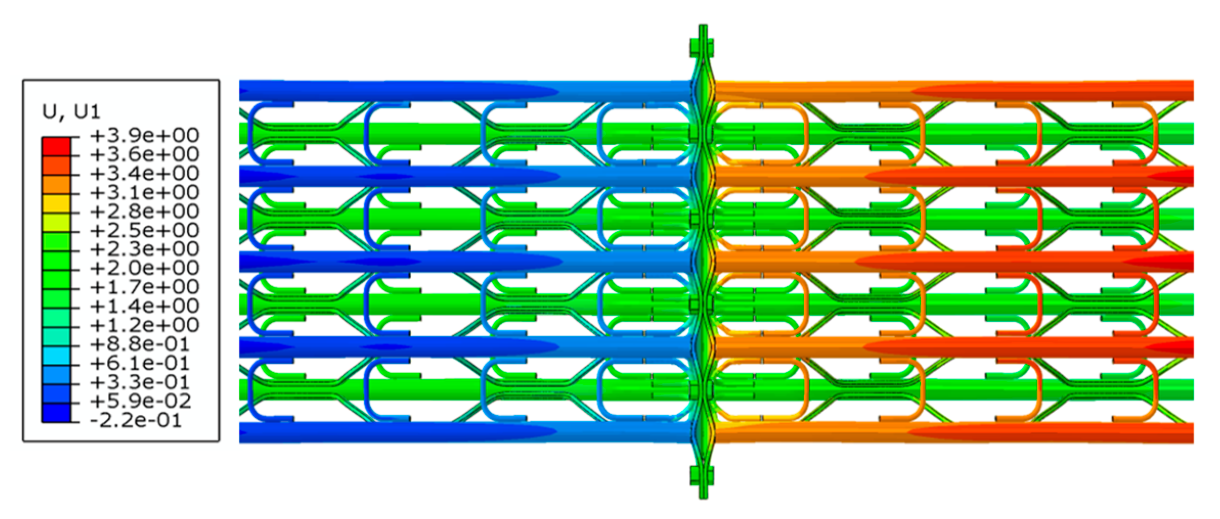
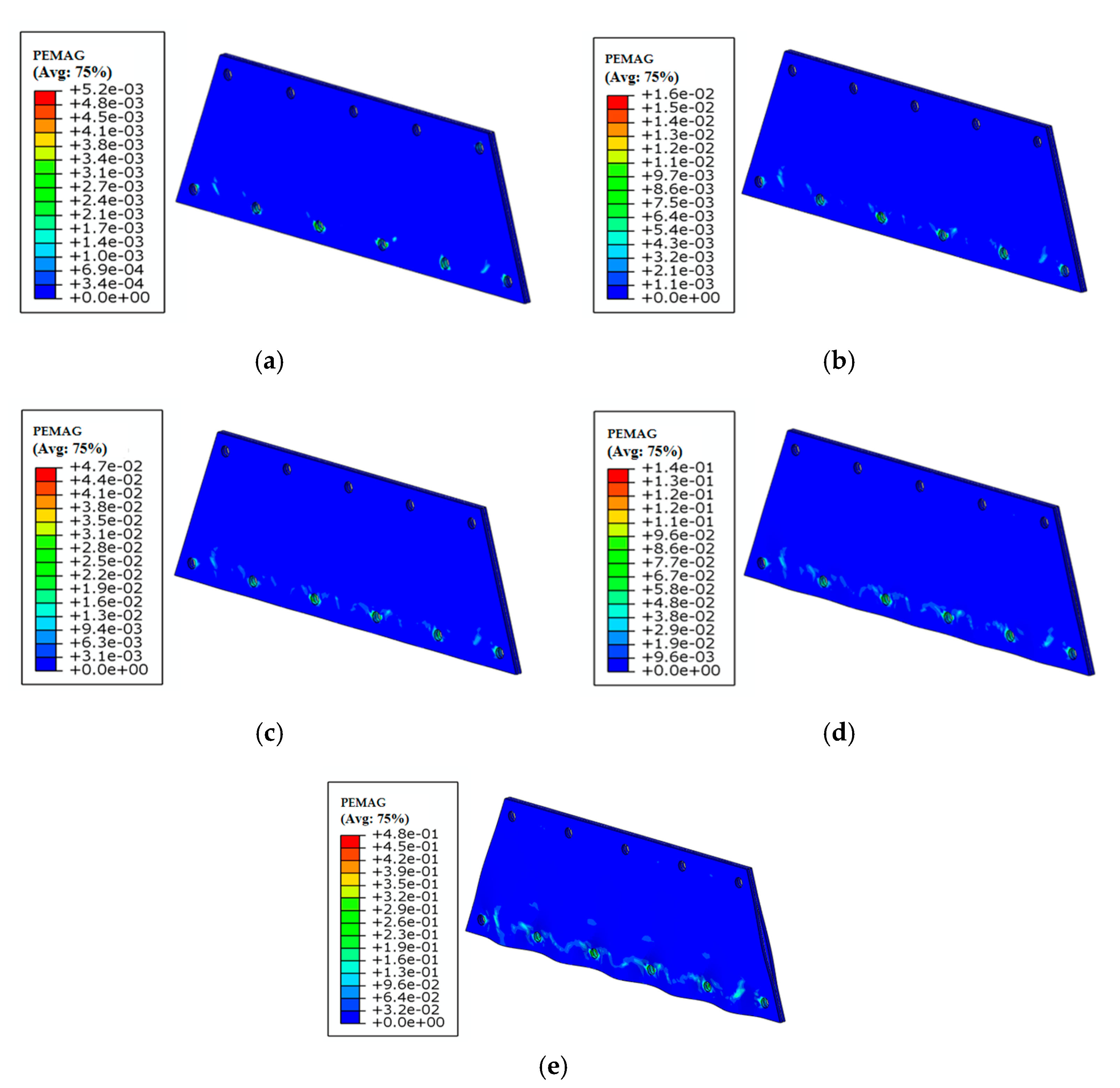
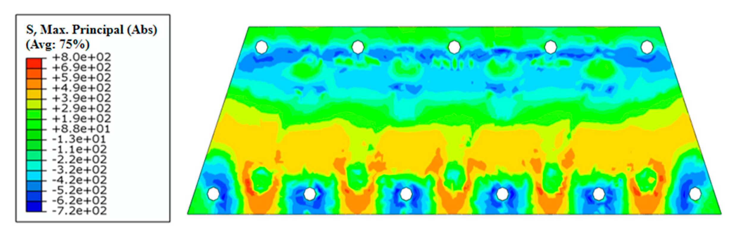
5. Finite Element Analysis

Numerical simulation is more and more widely used to analyze the deformation and failure of engineering structures. In this paper, the stress, deformation characteristics, and failure mechanism of SSTG arches are analyzed by using numerical method, and are compared with the experimental results.

5.1. Numerical Modeling

The general finite element software ABAQUS is used to carry out the analysis of the bending performance of SSTG arches under combined axial force and bending load, and a three-dimensional refined full-scale entity model is established. The model mainly includes the following six types of components: main limb steel tube, π-shaped rebar, U-shaped rebar, trapezoidal flange plate, high-strength bolt and bearing. As shown in Figure 17, the FE mesh of steel tubes, flange plates, and bolts in the model are achieved by using eight-node linear hexahedral incompatible element (C3D8I), which can overcome the shear self-locking problem, and suitable for elastic-plastic analysis and complex contact problems. The stress and deformation characteristics of the flange plate and bolts are the focus of this experimental study. The appropriate mesh density is determined, and refined at the stress concentration locations. In this paper, the simulated components are appropriately simplified, the influence of stirrups is not considered in the modeling, and the nut and the screw are assembled into one part instead of the threaded connection.

5.2. Contact Setting and Bolt Load

Tie constraint is set to realize the fixed connection of the steel tube with the steel bar and the flange plate. The bearing and the steel tube define the surface-to-surface contact properties, the normal behavior adopts hard contact, and the tangential behavior defines the penalty function. The contact surfaces between flange plates and high-strength bolts are also set face-to-face contact.
The bolt preload is simulated by the method of defining the bolt load. Considering the convergence of the model calculation, a small amount of preload is applied to the bolts after setting the initial analysis step to establish a stable contact relationship between the bolts and flange plate. In the next analysis step, the bolt preload is increased to the final preload, and the bolt load definition method is changed to maintain the current bolt length in the subsequent analysis step. When the strain of the crucial parts in the model reaches the elastic-plastic limit value, it can be considered that the specimen has been damaged, and then the ultimate bearing capacity and failure form can be obtained.

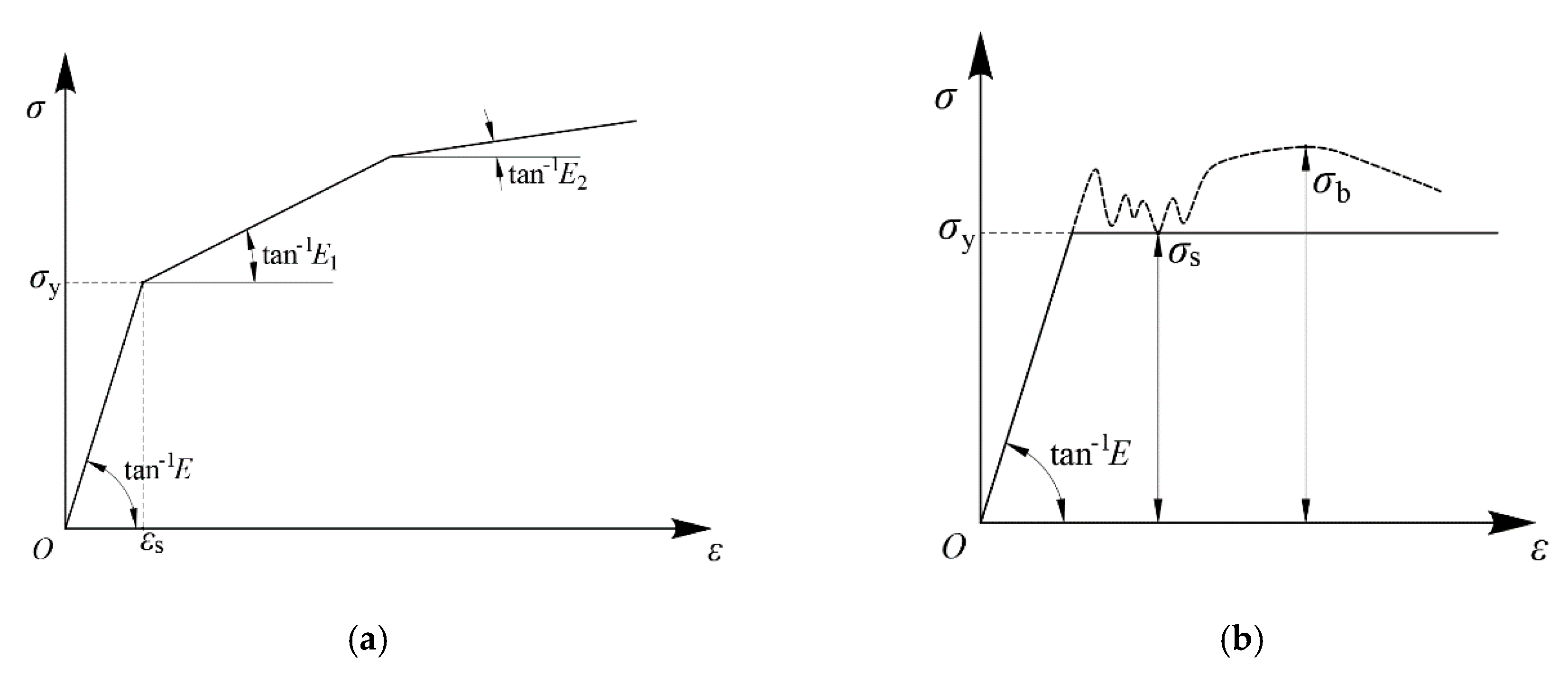
5.3. Material Parameters

For steel tube, yield stress fy = 420 MPa, the modulus of elastic ES = 2.06 × 10⁵ MPa. For connecting rebar, yield stress fy = 400 MPa, the modulus of elastic ES = 2.06 × 10⁵ MPa. For flange plate, yield stress fy = 235 MPa, the modulus of elastic ES = 2.06 × 10⁵ MPa. For high-strength bolt, yield stress fy = 900 MPa, the modulus of elastic ES = 2.1 × 10⁵ MPa. Poisson’s ratio 0.3 is considered.
The steel tube and the connecting rebar are low-alloy high-strength steel, there is no obvious yield point and yield step on the stress–strain curve. Meanwhile, considering the strengthening effect, a three-fold line-strengthening elastic-plastic model is selected for analysis, the stress–strain relationship is shown in the Figure 18a. Besides, the flange plate is made of carbon structural steel, and its yield condition is studied using an ideal elastic-plastic model. The stress–strain relationship is shown in Figure 18b.

5.4. Results and Discussion

A concentrated force is applied in the horizontal direction to simulate the axial load, and a vertical concentrated load is applied to simulate the bending moment of the joint. Under the combined load, Figure 19 and Figure 20 show the vertical displacement characteristics of the specimen. The results indicate that the main limb steel tubes have large deformation and the maximum displacement occurs at the joint. In summary, the numerical results are in good agreement with the experimental results. Therefore, it is reliable to employ numerical simulation method to study the mechanical properties of steel structures.
The joint opening deformation and the total load curves reflect the mechanical behavior of SSTG arches, as shown in Figure 21 and Figure 22. The results reveal the deformation and failure characteristics of the flange plates, which on the tensioned side produce bell-mouth opening deformation under the influence of the tension of the main limb steel tubes, and the amount of deformation is directly related to the load. In the initial stage of loading, the joint opening of the specimen changes linearly with the increase of the load, while the growth rate is relatively slow. As the load continues to be applied, the deformation rate of the joint opening gradually increases. When the bending moment reaches about 270 kN·m, the specimen reaches yield strength, and the deformation rate is significantly accelerated.
Figure 23 shows the process of plastic strain and failure of the flange plate. It indicates that the plastic zone of the flange plate is mainly concentrated around the bolt holes and the connection between the main limb steel tubes and the flange plates on the tension side. These areas are prone to large deformation, and are more likely to reach yield strength and fail. In the initial stage of loading, the flange plates are in the elastic deformation stage without plastic strain. With the further increase of the load, the distribution range of the plastic zone gradually expands to the vicinity, and the value of the plastic strain continues to increase until the specimens reach ultimate bearing state. When the bending moment is 200 kN·m, the maximum plastic strain value of the flange plates is 0.016. When the bending moment is 300 kN·m, the maximum plastic strain value of the flange plates improves to 0.144. At the same time, it can be seen that the flange plates on the tension side have certain regular opening deformation between the bolts, and a cavity is formed between the flange plates.
Figure 24 shows the yield failure state of the flange plate. It can be seen that the flange plate shows obvious compression zone and tension zone, and the boundary is clear. Moreover, the areas around the bolt holes on the tension side and most areas on the compression side are in compression state. The connection between the steel tubes and the flange plate on the tension side, and the connecting areas formed by the adjacent steel tubes are in tension state. Thus, these results mentioned above are in good agreement with the experimental results and also reflect the accuracy of the numerical calculation.
Figure 25 presents the distribution nephograms of stress and strain of the high-strength bolts. The bolts on the tension side bear greater stress than the bolts on the compression side, and a few nodes of the screw and nut exceed the yield strength. Meanwhile, the plastic zone is mainly concentrated on the tension side bolts. The bolts on the compression side are overall in good condition and basically in the elastic deformation stage. The working situations of bolts at different positions on the same side are also different, the stress and plastic zone of bolt 1# and bolt 6# is smaller than other four bolts. There is no obvious bending deformation and failure for all bolts. In general, the whole bolts are reasonably stressed and deformed and have a high degree of safety redundancy.
By extracting the stress on the screw section to obtain the bolt tension, then the curve of bending moment-bolt axial force is shown in Figure 26. In the initial stage of loading, the axial force of the whole bolts remains basically unchanged. When the bending moment increases to 225 kN·m, the growth rate of the bolts on the tension side increases significantly, and the growth trend is similar. The bolt 2#, bolt 3#, bolt 4#, and bolt 5# bear greater tensile force, but none of the bolts exceeds the critical yield strength. The axial force of the bolts on the compression side remains basically unchanged during the initial and middle stage of loading, and decreases to a certain extent in the late stage of loading, which is consistent with the experimental results.

6. Conclusions

In this paper, based on the subsurface excavation tunnel project of Panyu Square Station of Guangzhou Metro, SSTG arch is proposed for the first time. Combined with model experiment and numerical simulation, the mechanical characteristic and failure mode of SSTG arches are analyzed. The results in this study can be summarized as:
(1)
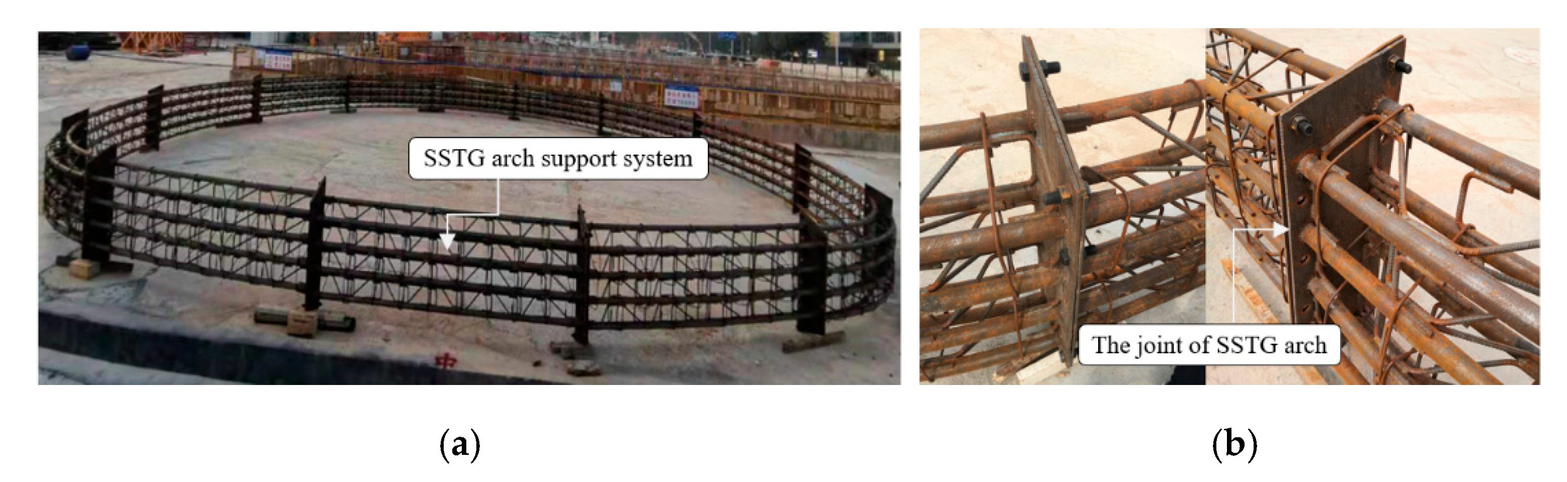
A new support technology of spatial steel tubular grid (SSTG) arch is proposed, in which high-strength seamless steel tube is used as the main load-bearing member, high-strength π-shaped rebar + U-shaped rebar are used as connecting rebar, and trapezoidal flange plate + high-strength bolts are used as the main connection of the joints. The SSTG arch has good mechanical performance with high strength and rigidity, which can bear the load of surrounding rock in real time, and ensure the safety of tunnel construction.
(2)
During the whole process of loading, the specimens experience elastic growth stage, plastic development stage, and final failure stage. The average ultimate bending moment of the three groups of specimens is about 340.5 kN·m, and the corresponding joint opening is about 13.9 mm.
(3)
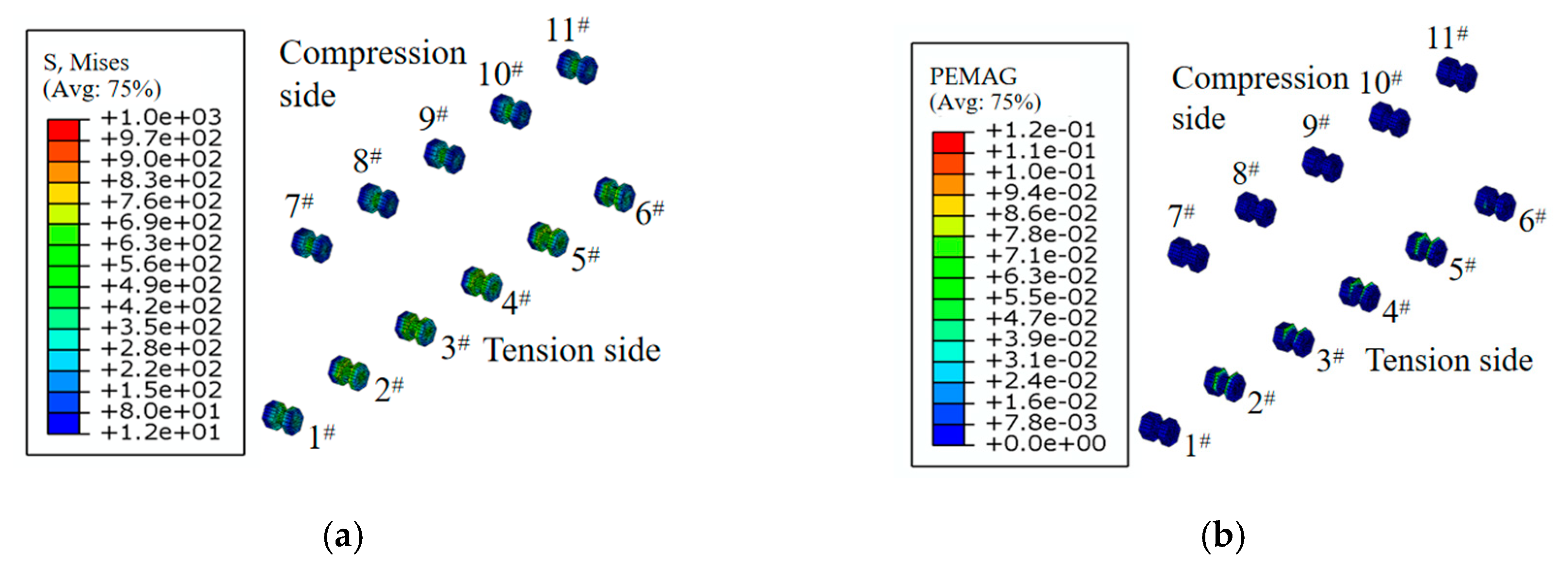
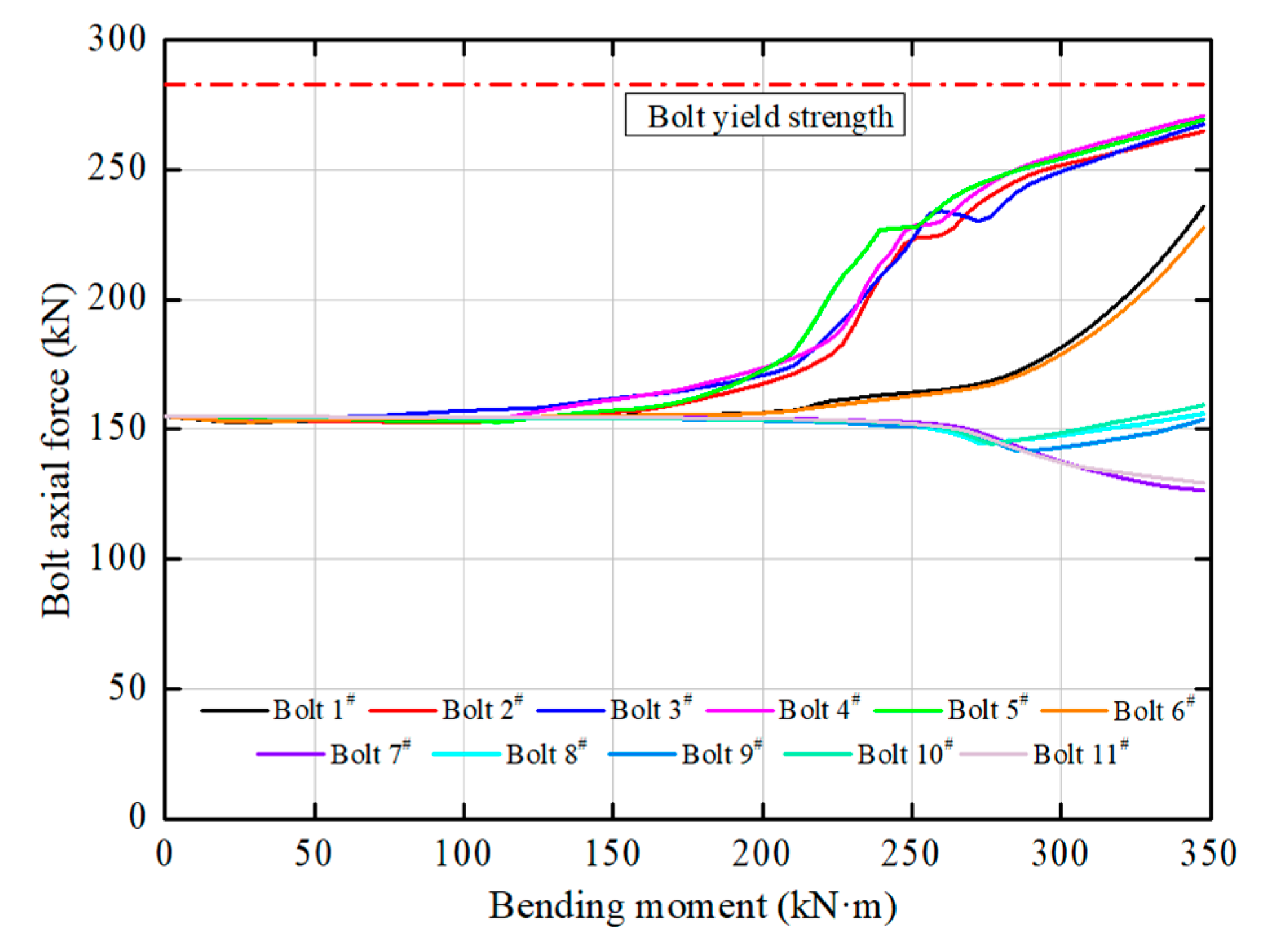
The main limb steel tube is mainly subjected to bending deformation, and there is a certain degree of necking and sagging without obvious yield failure. The bolts on the tension side bear more tensile force, and the plastic zone is more widely distributed than the boils on the compression side. In addition, the bolts on the compression side are basically in the elastic deformation stage, and are still in good condition until the end of the loading. Furthermore, the π-shaped rebar shows obvious deformation and is broken locally during the loading process.
(4)
The failure of the specimen is mainly due to the plastic yield of the flange plates. The flange plates on the tension side have obvious opening deformation. In the yield stage, the opening deformation rate is significantly accelerated. Therefore, in engineering application, the thickness of flange plate could be appropriately increased to improve the anti-deformation ability of circumferential joint.
In this paper, a new support technology of spatial steel tubular grid (SSTG) arch was designed independently. Moreover, the mechanical properties and field application of the new SSTG arch were carried out in combination with the Guangzhou stratum condition, and the mechanical characteristic and failure mode of SSTG arches had made clear. Test results also provided a theoretical basis for the design and application of SSTG arch support in other related projects. In the subsequent researches, the support system and bearing mechanism of the SSTG arch will be further improved according to factors such as different surrounding rock grades and tunnel depth, so as to form a complete set of supporting technology for tunnels with high geo-stress and soft broken surrounding rock.

Author Contributions

Conceptualization, Y.S., M.H.; methodology, Y.S., M.H., and X.Z.; software, Y.S., Z.L.; validation, Y.S., M.H., and Z.L.; formal analysis, Y.S.; investigation, Y.S., X.P.; resources, M.H., X.Z.; writing—original draft preparation, Y.S.; writing–review and editing, Y.S.; supervision, M.H. and Z.L. All authors have read and agreed to the published version of the manuscript.

Funding

This research was funded by the National Key R&D Program of China (2018YFC0808705).

Acknowledgments

The authors gratefully acknowledge the financial support of the National Key R&D Program of China (2018YFC0808705).

Conflicts of Interest

The authors declare no conflict of interest.

References

  1. Wang, D.Y.; Liu, J.; Zhang, C.; Yuan, J.X.; Zhu, Y.Q.; Liu, H.; Cui, G.Y. Field tests on large deformation control method for surrounding rock of deep tunnel in fault zone with high geostress. Chin. J. Geotech. Eng. 2020, 45, 658–666. [Google Scholar]
  2. Fang, X.H.; Yang, Z.; Yang, J.S.; Peng, X.J.; Tang, Y.; Liu, W.L. Large Deformation Characteristics and Control Measures of Surrounding Rock in Altered Granite Stratum of High Ground Stress Tunnel. China Railw. Sci. 2020, 41, 92–101. [Google Scholar]
  3. Baumann, T.H.; Betzle, M. Investigation of the performance of lattice girders in tunnelling. Rock Mech. Rock Eng. 1984, 17, 67–81. [Google Scholar] [CrossRef]
  4. Nomikos, P.P.; Sofianos, A.I.; Sakkas, K.M.; Choumanidis, D.; Delendas, S. Nonlinear simulation of lattice girder segment tests. Tunn. Undergr. Space Technol. 2013, 38, 180–188. [Google Scholar] [CrossRef]
  5. Kim, H.J.; Song, K.I.; Jung, H.S.; Shin, Y.W.; Shin, J.H. Performance evaluation of lattice girder and significance of quality control. Tunn. Undergr. Space Technol. 2018, 82, 482–492. [Google Scholar] [CrossRef]
  6. Kim, S.; Han, T.H.; Baek, J.S.; Kang, Y.J. Evaluation of the structural performance of tetragonal lattice girders. Int. J. Steel Struct. 2013, 13, 31–47. [Google Scholar] [CrossRef]
  7. Qiu, W.G.; Lu, F.; Wang, G.; Huang, G.; Zhang, H.J.; Zhang, Z.Y.; Gong, C. Evaluation of mechanical performance and optimization design for lattice girders. Tunn. Undergr. Space Technol. 2019, 87, 100–111. [Google Scholar] [CrossRef]
  8. Zhang, D.L.; Chen, F.B.; Fang, Q. Study of mechanical characteristics and applicability of primary lining used in tunnel. Chin. Eng. Mech. 2014, 31, 78–84. [Google Scholar]
  9. Tan, Z.S. Application experimental study of high strength lattice girders with heat treatment in tunnel engineering. Hazard Control Tunn. Undergr. Eng. 2019, 1, 86–92. [Google Scholar]
  10. Yu, F.C.; Zhang, D.L.; Fang, Q.; Tai, Q.M.; Sun, Y. Experimental study of characteristics of composite support with high strength reinforcing lattice girders embedded in concrete. China Civ. Eng. J. 2015, 48, 104–111. [Google Scholar]
  11. Li, W.T.; Yang, N.; Yang, B.; Ma, H.Y.; Li, T.C.; Wang, Q.; Wang, G.; Du, Y.T.; Zhao, M.X. An improved numerical simulation approach for arch-bolt supported tunnels with large deformation. Tunn. Undergr. Space Technol. 2018, 77, 1–12. [Google Scholar] [CrossRef]
  12. Du, B.J.; Liu, C.Y.; Wu, F.F.; Yang, J.X. Deformation mechanism and control technology of roadway in deep mine with high stress and weak surrounding rock. J. Min. Saf. Eng. 2020, 37, 1123–1132. [Google Scholar]
  13. Jing, H.W.; Wu, J.Y.; Yin, Q.; Wang, K. Deformation and failure characteristics of anchorage structure of surrounding rock in deep roadway. Int. J. Min. Sci. Technol. 2020, 30, 593–604. [Google Scholar] [CrossRef]
  14. Yokota, Y.; Zhao, Z.Y.; Nie, W.; Date, K.; Iwano, K.; Koizumi, Y.; Okada, Y. Development of a new deformation-controlled rock bolt: Numerical modelling and laboratory verification. Tunn. Undergr. Space Technol. 2020, 98, 103305. [Google Scholar] [CrossRef]
  15. Xu, F.; Li, S.C.; Shi, S.S.; Li, L.P.; Wang, W.M.; Zhang, W.; Zhang, Q.Q.; He, P. Field test comparison of traditional and new type supporting structures in a phyllite tunnel. Chin. J. Rock Mech. Eng. 2017, 36, 609–621. [Google Scholar]
  16. Pang, J.Y.; Huang, J.K.; Liu, G.C.; Zhang, J.S. Experimental study on the structure of reinforced concrete reticulated shell support in soft rock roadway. J. Min. Saf. Eng. 2020, 37, 655–664. [Google Scholar]
  17. Li, X.B.; Yang, R.S.; Gao, Y.F.; Xue, H.J. Study on combined support technology of bolt-mesh-shotcrete and concrete filled steel tubular supports for soft rock roadway in Yangzhuang mine. J. Min. Saf. Eng. 2015, 32, 285–290. [Google Scholar]
  18. Liu, D.J.; Zuo, J.P.; Wang, J.; Zhang, T.L.; Liu, H.Y. Large deformation mechanism and concrete-filled steel tubular support control technology of soft rock roadway-A case study. Eng. Fail. Anal. 2020, 116, 104721. [Google Scholar] [CrossRef]
  19. Sun, H.B.; Li, S.C.; Wang, Q.; Zhou, L.S.; Jiang, B.; Zhang, X.; Xu, S.; Zhang, H.J. Research and application of fabricated confined concrete construction system for large cross section tunnel. China J. Highw. Transp. 2018, 31, 320–327. [Google Scholar]
  20. Wang, Q.; Xin, Z.X.; Jiang, B.; Sun, H.B.; Xiao, Y.C.; Bian, W.H.; Li, L.N. Comparative experimental study on mechanical mechanism of combined arches in large section tunnels. Tunn. Undergr. Space Technol. 2020, 99, 103386. [Google Scholar] [CrossRef]
  21. Li, S.C.; Lu, W.; Wang, Q.; Sun, H.B.; Jiang, B.; Qin, Q. Study on failure mechanism and mechanical properties of casing joints of square steel confined concrete arch. Eng. Fail. Anal. 2018, 92, 539–552. [Google Scholar] [CrossRef]
  22. Lu, W.; Sun, H.B. Study on support characteristic curve of concrete-filled steel tubular arch in underground support. Structures 2020, 27, 1809–1819. [Google Scholar] [CrossRef]
  23. Li, W.T.; Yang, N.; Mei, Y.C.; Zhang, Y.H.; Wang, L.; Ma, H.Y. Experimental investigation of the compression-bending property of the casing joints in a concrete filled steel tubular supporting arch for tunnel engineering. Tunn. Undergr. Space Technol. 2020, 96, 103184.1–103184.17. [Google Scholar] [CrossRef]
  24. Zhang, X.N.; Zhang, Y.; Shan, R.L.; Bai, Y.T.; Zhang, Z.H. Application on bending performance of annular concrete-filled steel tube stent. J. Constr. Steel Res. 2020, 168, 105984. [Google Scholar] [CrossRef]
  25. Wang, Q.; Xu, S.; Jiang, B.; Li, S.C.; Xiao, Y.C.; Xin, Z.X.; Liu, B.H. Research progress of confined concrete support theory and technology for underground engineering. J. China Coal Soc. 2020, 45, 2760–2776. [Google Scholar]
  26. China Machinery Industry. GB/T 1231-2006, Specifications of High Strength Bolts with Large Hexagon Head, Large Hexagon Nuts, Plain Washers for Steel Structures; Standards Press of China: Beijing, China, 2006. [Google Scholar]
  27. China Machinery Industry. GB 50017-2017, Standard for Design of Steel Structures; China Architecture & Building Press: Beijing, China, 2017. [Google Scholar]
Figure 1. Spatial steel tubular grid (SSTG): (a) assembled into a ring on the ground; (b) flange plates and bolts in circumferential joint.
Symmetry 12 02065 g001
Figure 2. Research contents and technical route.
Symmetry 12 02065 g002
Figure 3. The geographical location of the Heng-Pan interval tunnel at Panyu Square Station in Guangzhou.
Symmetry 12 02065 g003
Figure 4. The on-site assembly of the arch.
Symmetry 12 02065 g004
Figure 5. SSTG arch specimen for the test.
Symmetry 12 02065 g005
Figure 6. SSTG arch structure (Unit: mm): (a) section structure of SSTG arch; (b) connection form of circumferential joint.
Symmetry 12 02065 g006
Figure 7. Loading scheme (Unit: mm).
Symmetry 12 02065 g007
Figure 8. Loading in progress.
Symmetry 12 02065 g008
Figure 9. Layout of measuring points: (a) main limb steel tubes; (b) flange plate; (c) π-shaped connecting bars; (d) bolts.
Symmetry 12 02065 g009
Figure 10. Comparison between initial state and final failure state of SSTG arches: (a) initial state; (b) final failure state.
Symmetry 12 02065 g010
Figure 11. Bending moment–mid-span deflection curve.
Symmetry 12 02065 g011
Figure 12. Bending moment–joint opening curve.
Symmetry 12 02065 g012
Figure 13. Bending moment–steel tubes strain curves: (a) Section 1; (b) Section 2.
Symmetry 12 02065 g013
Figure 14. Bending moment–flange plate strain curves: (a) strain of measuring points of FL-1~FL-9; (b) strain of measuring points of FL-10~FL-24.
Symmetry 12 02065 g014
Figure 15. Bending moment–π-shaped rebar strain curves.
Symmetry 12 02065 g015
Figure 16. Bending moment–bolt axial force curves.
Symmetry 12 02065 g016
Figure 17. FE model.
Symmetry 12 02065 g017
Figure 18. Stress–strain relationship of elastic-plastic model of steel materials: (a) high-strength alloy steel; (b) low-carbon steel.
Symmetry 12 02065 g018
Figure 19. The nephogram of vertical displacement.
Symmetry 12 02065 g019
Figure 20. Bending moment–mid-span deflection curves.
Symmetry 12 02065 g020
Figure 21. The nephogram of the joint opening.
Symmetry 12 02065 g021
Figure 22. Bending moment—joint opening curves.
Symmetry 12 02065 g022
Figure 23. Nephograms of plastic strain and failure of flange plates: (a) bending moment 150 kN·m; (b) bending moment 200 kN·m; (c) bending moment 250 kN·m; (d) bending moment 300 kN·m; (e) bending moment 350 kN·m.
Symmetry 12 02065 g023
Figure 24. The nephogram of maximum principal stress of the flange plate.
Symmetry 12 02065 g024
Figure 25. Stress and strain nephograms of the bolts (bending moment 350 kN·m): (a) stress nephogram; (b) strain nephogram.
Symmetry 12 02065 g025
Figure 26. Bolts axial force and bending moment curves.
Symmetry 12 02065 g026
Table 1. Main physical and mechanical parameters of test specimens (Unit: mm).
Steel Tubeπ-Shaped RebarU-Shaped RebarFlange PlateBolt
MaterialSizeMaterialDiameterMaterialDiameterMaterialthicknessGradeSize
Q420Φ50 × 8HRB40014 HRB40014 Q235B1010.9M20
Table 2. Experiment conditions.
Working ConditionHorizontal Load (kN)Vertical Load (kN)Bending Moment (kN·m)
Design condition640412200
Failure condition640614298
Table 3. Summary of measuring points.
Test ItemMeasuring RangeAccuracyQuantity
The strain of steel tube0~0.021 × 10−618
The strain of flange plate0~0.021 × 10−624
The strain of π-shaped connecting rebar0~0.021 × 10−68
Bolt axial force0~300 kN0.5 kN6
Mid-span deflection0~100 mm0.1 mm2
Joint opening0~50 mm0.1 mm2
Publisher’s Note: MDPI stays neutral with regard to jurisdictional claims in published maps and institutional affiliations.

