Article

Computational Fluid Dynamics Study of Magnus Force on an Axis-Symmetric, Disk-Type AUV with Symmetric Propulsion

Institute of Marine Structures and Naval Architecture, Ocean College, Zhejiang University, Zhoushan 316000, China
*
Author to whom correspondence should be addressed.
Symmetry 2019, 11(3), 397; https://doi.org/10.3390/sym11030397
Submission received: 18 February 2019 / Revised: 14 March 2019 / Accepted: 16 March 2019 / Published: 19 March 2019

Abstract

:
In this paper, the Magnus force induced by a disk-type, spinnable autonomous underwater vehicle (AUV), i.e., autonomous underwater helicopter (AUH), was predicted to promote the spinning AUH moving away from a deep-sea region with temporary and shockable ocean current. The simulation technique of the ANSYS-CFX solver based on viscous computational fluid dynamics (CFD) was employed to analyze the hydrodynamic performance of the spinning AUH and its high-speed propellers in uniform flow conditions. The behavior of the spinning AUH in currents can obviously alter the pressure distribution on both sides of the disk-shaped hull form, resulting in a differential pressure force in the horizontal plane, i.e., Magnus force. The simulation results show that this induced force can enable an AUH at 1 knot service speed to successfully move away from a sudden, transient, and/or steady, uniform ocean current region with inflow velocities of 1–2 knots in deep-sea conditions. The Magnus force induced by symmetrically configurated propeller couple force can be more efficient and effective at driving the AUH’s escape from the current spoiler zone than driving the AUH using the two high-revolution propellers directly. A suitable mechanical power energy-saving matching point integrating the AUH and symmetric propulsion was determined to compare the proposed method and two conventional methods for AUH escape from currents. The comparison results prove that the proposed method is effective and efficient. This study provides a significant reference for the interdependent relationship between the effective spinning speed of an AUH, subject to couple force, controlled propeller revolution, AUH speed, and battery capacity, and the range of ocean currents.

1. Introduction

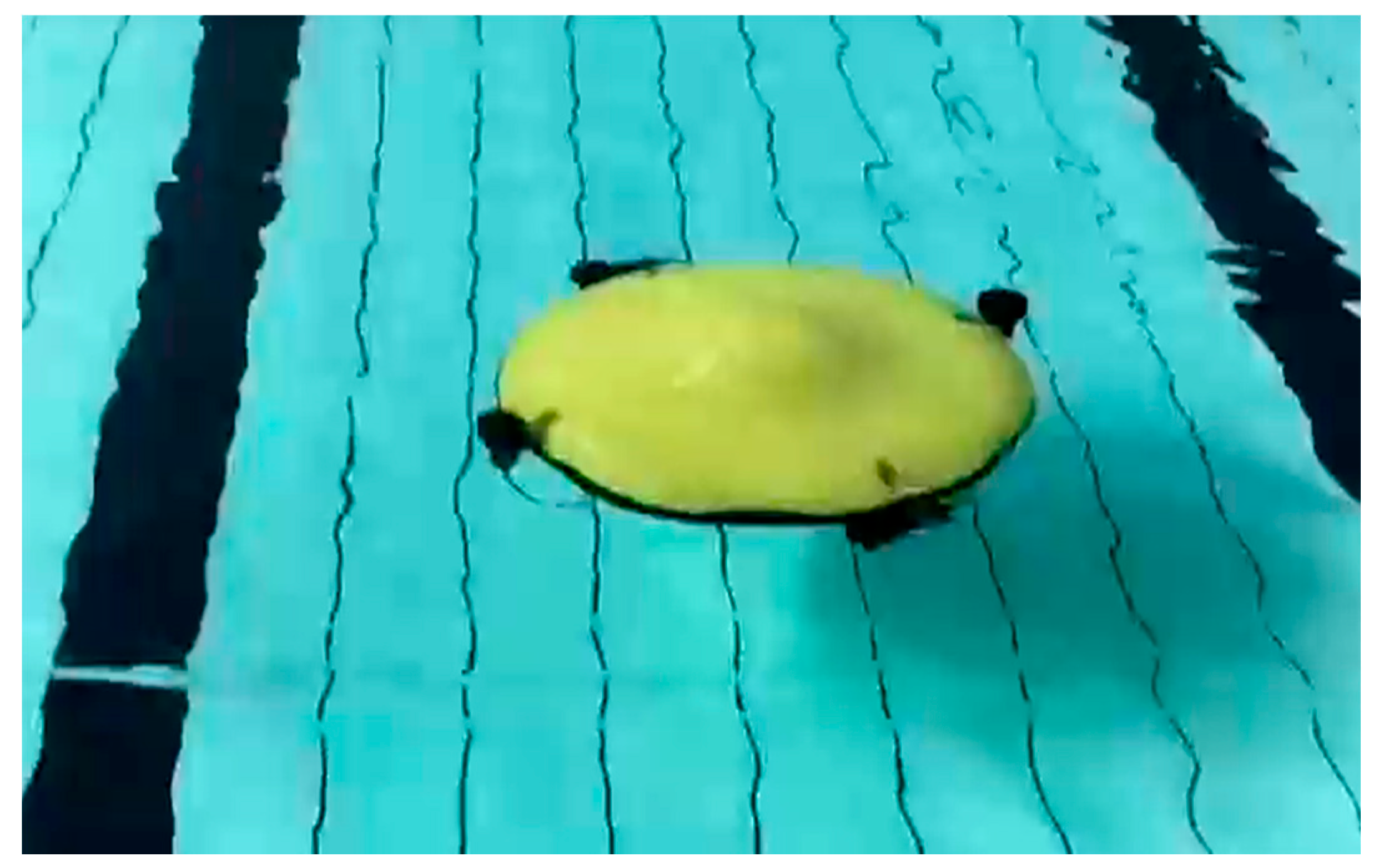
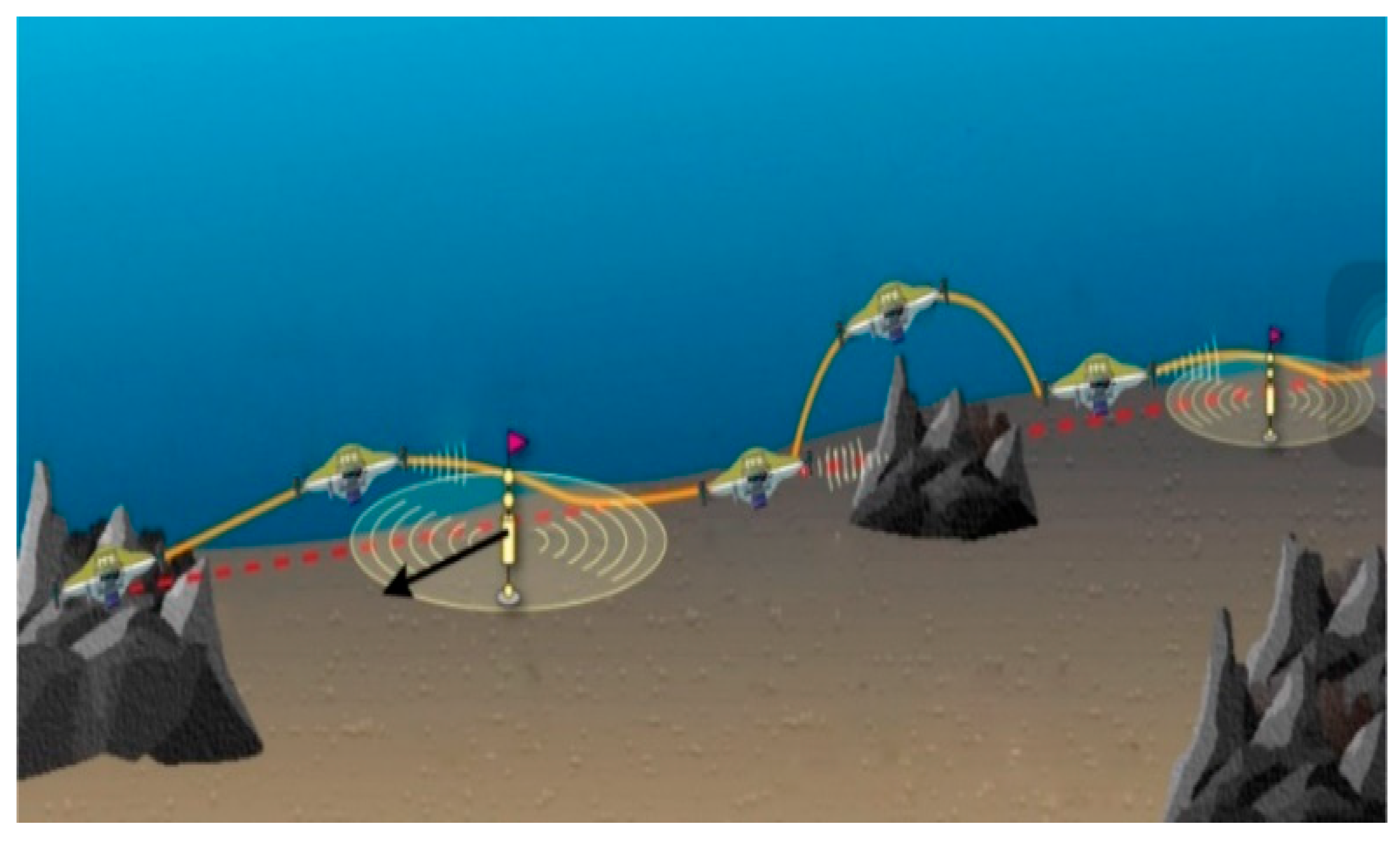
A torpedo-shaped, axis-symmetric slender body is undoubtedly the main appearance of conventional autonomous underwater vehicles (AUVs) [1,2,3], but it has poor maneuverability in sway due to the inefficiency of the control surfaces under low-velocity conditions, whereas it has good linear motion performance due to its streamlined shape [3]. In response to the complex environment under the sea, especially within temporary, shockable, steady, and/or unsteady ocean currents, an important requirement for the next generation of AUVs is to travel deeper and be more maneuverable while retaining stability [3,4,5]. Hence, a new type of AUV named “Autonomous Underwater Helicopter” (AUH), an axis-symmetric, disk-shaped underwater vehicle, was designed to meet this requirement in 2016 [6]. The structural design and a scale model of the AUH are shown in Figure 1 and Figure 2. A new operation mode of the AUH is working from seabed to seabed, as shown in Figure 3, which distinguishes it from the model of the conventional AUVs, which work from wave surface through deep sea and return to the wave surface. Because of the oceanic environment, the AUH will be disturbed by the ocean current, causing motion instability when it works under the sea [6].
In the literature, the Routh motion stability criteria [3,5,6,7] of vertical and horizontal planes for the axis-symmetric, disk-shaped AUH and torpedo-shaped AUVs consisting of linear hydrodynamic derivatives were implemented using the ANSYS-CFX computational fluid dynamics (CFD) solver [6]. The motion stability of the disk-shaped AUH has been studied to prove that the vertical motion stability of the AUH is better than that of conventional torpedo-shaped AUVs, and both are comparable in terms of their horizontal straight-line motion stability [3,6,7].
In recent years, high-performance AUVs have been mounted with over-actuated vectored propulsors, such as vectoring propellers [8] and water jets [9,10], for enhanced hover-capable ability and high maneuverability in oceanic disturbance flow fields. However, enhancing the anti-flow ability of AUVs still needs creative problem-solving, energy-saving, and time-saving methods.
In the horizontal plane, the disk-shaped AUV has prominent anti-flow ability [11] due to the Magnus effect [12], which can be generated by the spinning disk-shaped hull form in yaw. Compared with the torpedo-shaped AUVs [13,14,15], the disk-type AUH in this study has a better spinning performance, achieved by two symmetrically equipped vectoring propellers to produce a couple moment in yaw, as shown in Figure 2.
In this study, a further exploration of research work in the literature [11], a hydrodynamic analysis of the axis-symmetric, disk-type AUH’s spinning behavior was studied in order to better perform complex tasks under an ocean current. This research provides an important reference on the interdependent relationship between the effective spinning speed of the AUH mounted with propellers subjected to controlled propeller revolution, the AUH speed, battery capacity, and the range of the ocean current using the viscous computational fluid dynamics (CFD) simulation technique of the ANSYS-CFX solver [16,17,18]. A high-rotating-speed propeller model mounted with three blades was implemented using the ANSYS-CFX RANS (Reynolds-averaged Navier–Stokes equations) solver for simulating open water tests to predict the hydrodynamic performance, including the non-dimensionless propeller thrust, torque, and efficiency variation versus the advance ratio. Hence, the purpose of studying the spinning performance of the disk-type AUH mounted with a symmetrical propulsion system to generate anti-flow Magnus force was achieved through modeling a propeller loading coefficient, which was incorporated with the AUH resistance, effective horsepower, speed, propeller diameter, etc. The simulation results show that the Magnus force can be effective and efficient in driving the AUH away from a transient, uniform ocean current field. The proposed anti-flow method may be the most effective problem-solving method while the inflow direction and the yz plane of the body-fixed coordinates are orthogonal. The design parameters of the AUH are shown in Table 1.

2. Modeling the Equations of Motion

The coordinate systems for the dynamic formulations are presented in Figure 4. The body-fixed coordinate system is a Cartesian coordinate system with x, y, and z axes with the origin fixed on the AUH center of gravity (CG) and this coordinate is translating and rotating with the AUH; the sign conventions for roll, pitch, and yaw follow the right-hand rule relative to the x, y, and z axes, respectively. The Earth-fixed coordinate system of x0, y0, and z0 axes is referenced by the flow domain and the vehicle motion trajectory.
The equations of motion (EOMs) for the AUH are expressed in the body-fixed coordinate system. The EOMs consist of a surge equation, a sway equation, and a yaw equation as shown in Equation (1) [3,5]:
{ m ( u ˙ v r ) = X H C F D m ( v ˙ + u r ) = Y H C F D I z z r ˙ = N H C F D
where X denotes the force in surge; Y denotes the force in sway; N denotes the moment in yaw; the subscript H denotes the hydrodynamic forces or moments exerted on the AUH; the superscript CFD denotes the hydrodynamic forces and moments predicted by the viscous computational fluid dynamics (CFD) technique using the ANSYS-CFX solver; m denotes the AUH mass; Izz are the moments and products of inertia of the AUH; u and v denote the velocities in surge and sway, respectively; and r denotes the yaw rate.

3. RANS Solver (ANSYS-CFX)

The viscous fluid flow around the AUH was simulated using the commercial finite volume code in the ANSYS-CFX RANS solver, in which the appropriateness and validity of the turbulent model for turbulent flow CFD solutions are acceptable. The turbulent model adopted in this study was the shear stress transport (SST) model, i.e., k–ω [18], because the AUH has a disk-type geometry. The SST model is better than the conventional k–ε turbulent model for predicting separation to be found at the length of the run of the AUH [3,11]. In this study, to compare the hydrodynamic performance of the k–ε and k–ω (SST) turbulence models, both models were used to analyze the hydrodynamic performance of the spinning AUH at yaw rates of 1–6 rad/s. High-quality meshes are desirable in the analysis of the hydrodynamic performance of the AUH. The meshing software ANSYS-ICEM tool was adopted to produce the meshes in this study. The sliding meshes were applied to simulate the spinning ability of the AUH.

3.1. Mesh Generation

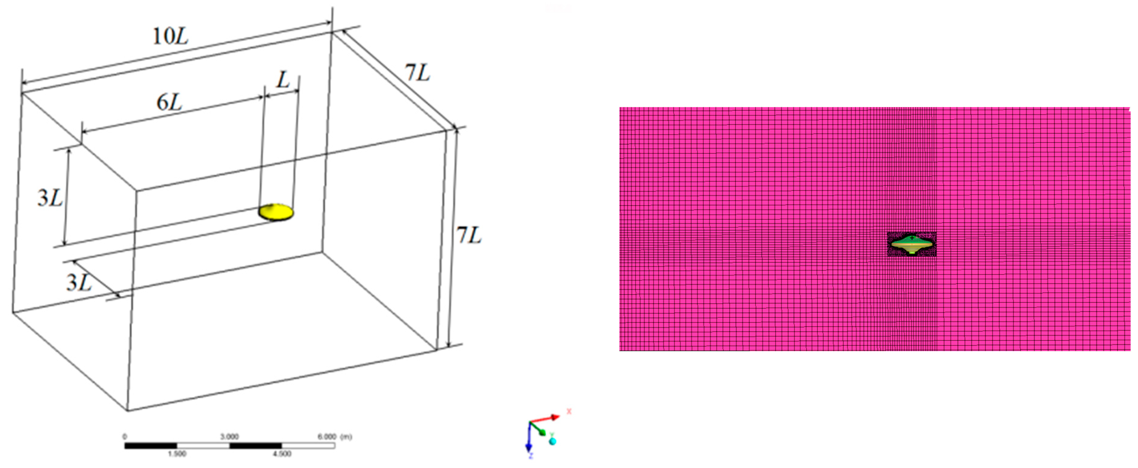
As shown in Figure 5, structured meshes of 2.05 million elements and 2.0 million nodes were constructed for this geometry, which emphasizes the mesh topology employed near the AUH and the special attention to resolving near-wall velocity gradients [6]. The first layer thickness of the boundary layer can be expressed as Equation (2) [5,6]:
Δ y = L Δ y + 80 Re 13 14
where Re denotes the Reynolds number defined as VL/γ, γ denotes the coefficient of kinematic viscosity, L denotes the diameter of the AUH, and 20 ≤ Δy+ ≤ 200 and Δy+ ≤ 5 using the k–ε and SST turbulence models, respectively.
In Figure 5a,b, the meshes around the AUH hull form transition from a refined mesh of modeling thicknesses of the boundary layer to a coarse mesh away from the hull form, extending out to form a cuboid fluid domain in which sliding meshes are integrated around the AUH hull form in Figure 5b for simulating the spinning disk-shaped AUH in uniform flow to generate the Magnus force for escaping the ocean current.

3.2. Boundary Conditions

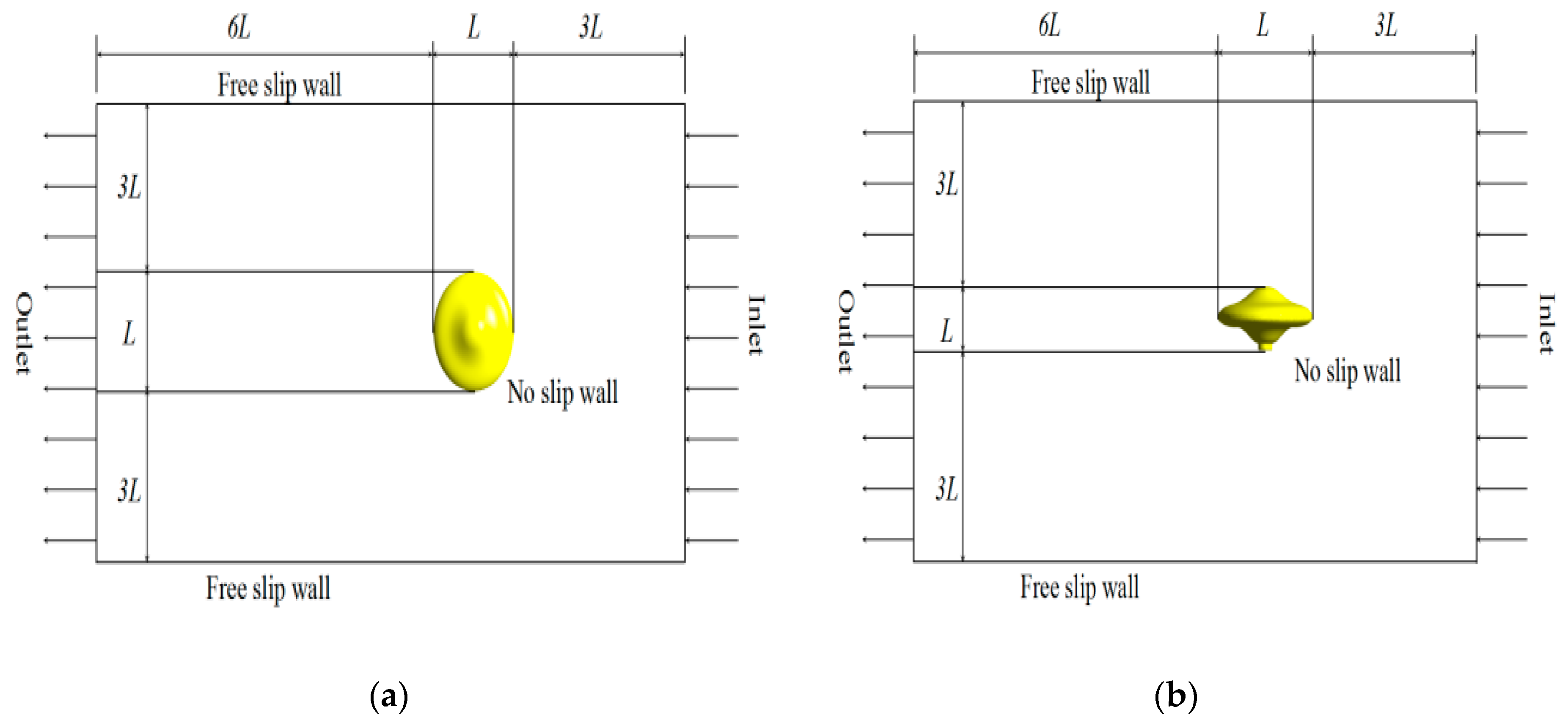
Firstly, an inlet boundary condition was located three body lengths upstream with respective inflow velocities of 1 and 2 knots and an inflow turbulence of 5% [3]. Secondly, an outlet boundary condition with zero relative pressure was located at six body lengths downstream. Thirdly, the hull of the AUH is the only solid boundary in the computational fluid domain and was set to a wall with a no-slip condition and different rotating velocities. Finally, free slip wall boundary conditions were applied to the four remaining boundaries which were three body lengths from the AUH, as shown in Figure 6 and Figure 7.

3.3. Computer Simulation

The solutions presented in the CFD simulations were calculated using the ANSYS-CFX high-resolution advection scheme. The residual convergence type was set to RMS, and the residual target set to 10–5. The details of the computational parameters applied to the CFD study on the spinning AUH in uniform flow are given in Table 2.

4. Simulation Results of Magnus Force

In this paper, the CFD simulation results of the hydrodynamic performance of the spinning AUH in various inflow velocities were considered to estimate the spinning speed, drag, and lateral force, i.e., Magnus force for the AUH to move away from the ocean current and to improve the AUH anti-flow maneuverability. Numerical simulations with uniform flow were performed at inflow velocities of 1–2 knots in the horizontal plane. The spinning speed was defined as part of the operational requirements, while the estimated Magnus force and drag were derived on the basis of the RANS CFD techniques.

4.1. Formulation of Hydrodynamic Performance

The drag and Magnus force coefficients relative to the spinning speed and freestream flow speed were divided by physical parameters, e.g., flow velocity, water density, and wetted area. Thus, these coefficients were expressed in term of non-dimensionalized coefficients as follows:
C D = F D 1 2 ρ V 2 S
C L = F L 1 2 ρ V 2 S
where FD and FL denote the drag and Magnus force, respectively; CD and CL denote the hydrodynamic coefficients of drag and Magnus force, respectively; S is the area of wetted surface of the hull projection in the xy plane, S = πL2/4; L is the max hull diameter; and V is the freestream flow speed. FD and FL were calculated using the ANSYS-CFX RANS solver.

4.2. Distribution of Pressure and Streamlines

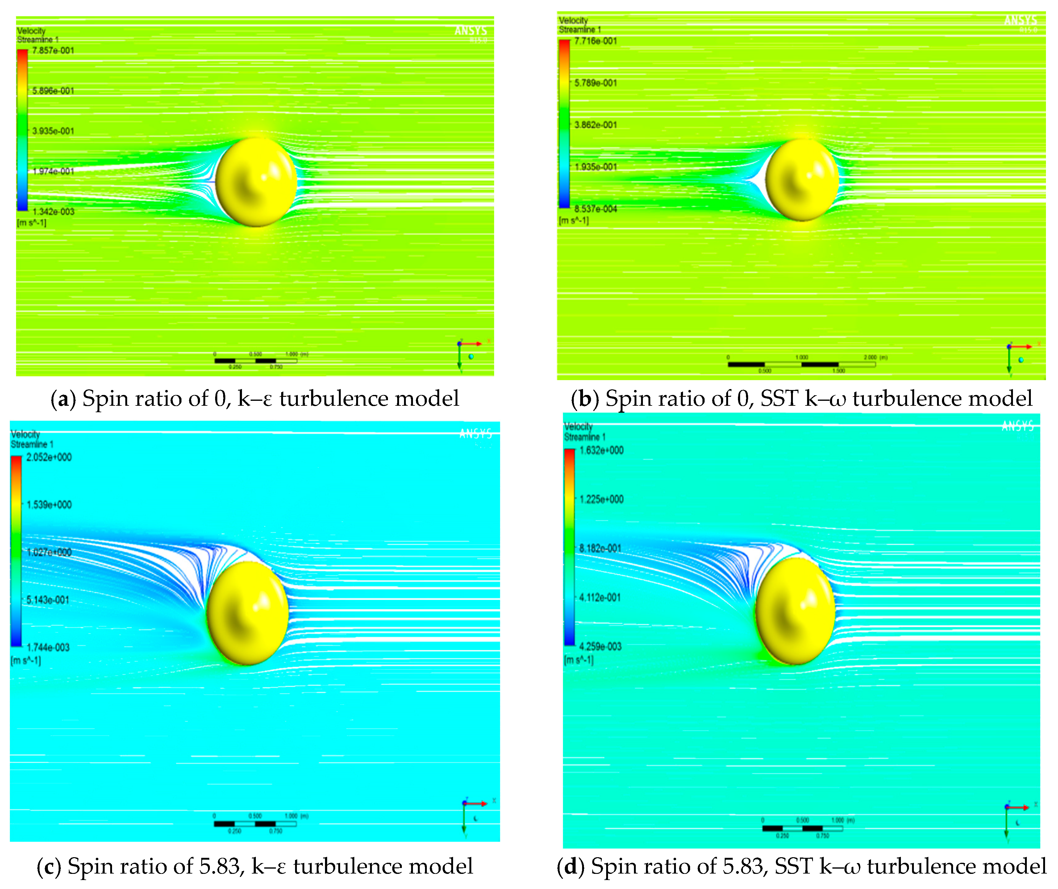
The most important parameter is the spin ratio, ωL/2V, which is the ratio of surface speed to freestream flow speed, where ω is the spinning speed of the AUH, L is the max hull diameter, and V is the freestream flow speed. Top views of the flow about the AUH with spin ratios of 0 and 5.83 using both the k–ε and k–ω (SST) turbulence models are shown in Figure 8.
The spinning AUH alters the pressure distribution over the hull form, as shown in Figure 9, and affects the location of boundary-layer separation. The AUH spinning direction is defined by the right-hand rule, and the clockwise spinning speed is positive in this paper. When the AUH moves along the +x direction, separation is delayed on the right-hand side surface of the AUH, as shown in Figure 8c,d, whereas it occurs earlier on the left-hand side surface of the AUH. The flow pressure is reduced on the right-hand side surface and simultaneously increased on the left-hand side surface; thus, the phenomenon of Magnus force was experienced through the pressure difference.

4.3. CFD Prediction of Hydrodynamic Coefficients

In this paper, CFD simulations with steady inflow were carried out at inflow velocities of 1 and 2 knots in the horizontal plane. The important studied parameter is the spin ratio, ωL/2V. The hydrodynamic coefficients of drag and Magnus force for the AUH are presented in Figure 10.
The simulation results from Figure 10 show that the drag coefficients increase consistently as the spin ratio increases, but they increase slowly above ωL/2V ≈ 4, and the values level out at about 0.13 at ωL/2V ≈ 6. No Magnus force will be generated if the AUH is translated without a spinning speed, as shown in Figure 10. Similar to the drag coefficients, the Magnus force coefficients increase consistently as the spin ratio increases but increase slowly above ωL/2V ≈ 2, and the values eventually level out at 0.58 at ωL/2V ≈ 6.
For both the k–ε and SST k–ω turbulence models, the simulation results have a similar trend with spin ratio increase. At different inflow velocity conditions, the numerical predictions of hydrodynamic coefficients using both k–ε and SST turbulence models have little deviation in this study, as shown in Figure 10. The coefficients of drag and Magnus force have maximal errors of 15% and 12% at ωL/2V ≈ 3, respectively, but the deviations become less pronounced as the spin ratio increases.
Two turbulence models were considered in this study. A clear phenomenon was that the numerical predictions of drag and Magnus force using the k–ω (SST) turbulence model were higher than the drag and Magnus force using the k–ε turbulence model. The flow and pressure distribution about the AUH also presented some discrepancies, as shown in Figure 8 and Figure 9. Because the k–ω (SST) model is better for predicting separation, the numerical predictions of drag and Magnus force using the k–ω (SST) turbulence model were considered as references in this study.
According to the CFD simulation results computed using the ANSYS-CFX RANS method and shown in Figure 10, the Magnus force generated by the AUH’s spinning behavior can drive the AUH away from the ocean current. The variations of drag with an inflow velocity of 1 knot and of Magnus force with an inflow velocity of 2 knots as spinning speed increases are shown in Figure 11. It is believed that an AUH with spinning speed greater than 3 rad/s can escape the ocean current at a speed greater than 1 knot in the condition of inflow velocity of 2 knots.
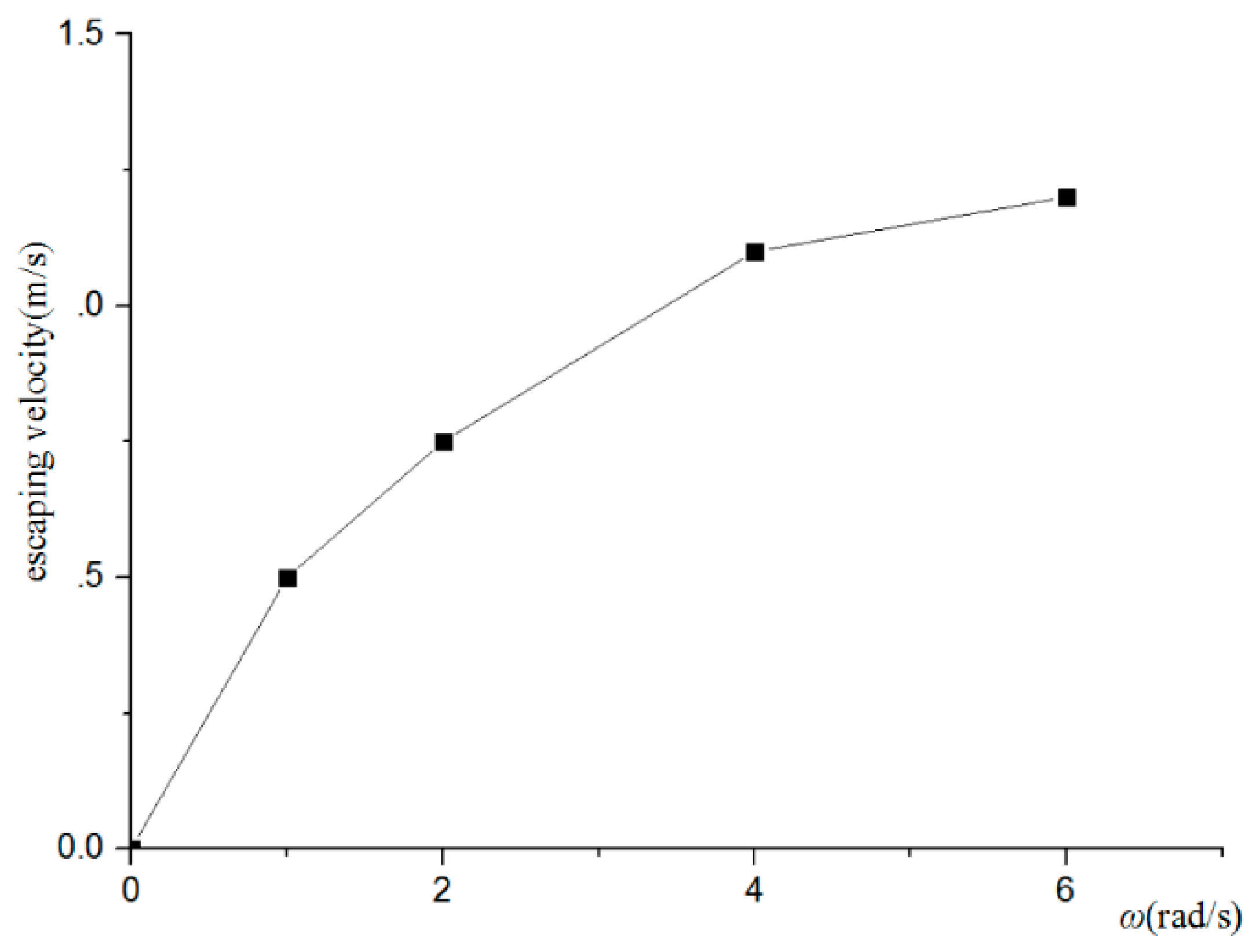
The velocity of the AUH escaping currents with an inflow velocity of 2 knots is shown in Figure 12. It can be seen that the escaping velocity of the AUH increases with the increase of the rotating speed, but the increasing trend gradually slows down. Therefore, increasing the rotating speed to increase the velocity of escaping from the currents is not the best solution for AUHs that can only carry limited battery energy.

5. Hydrodynamic Performance of the High-Speed Propeller

5.1. Mesh Generation

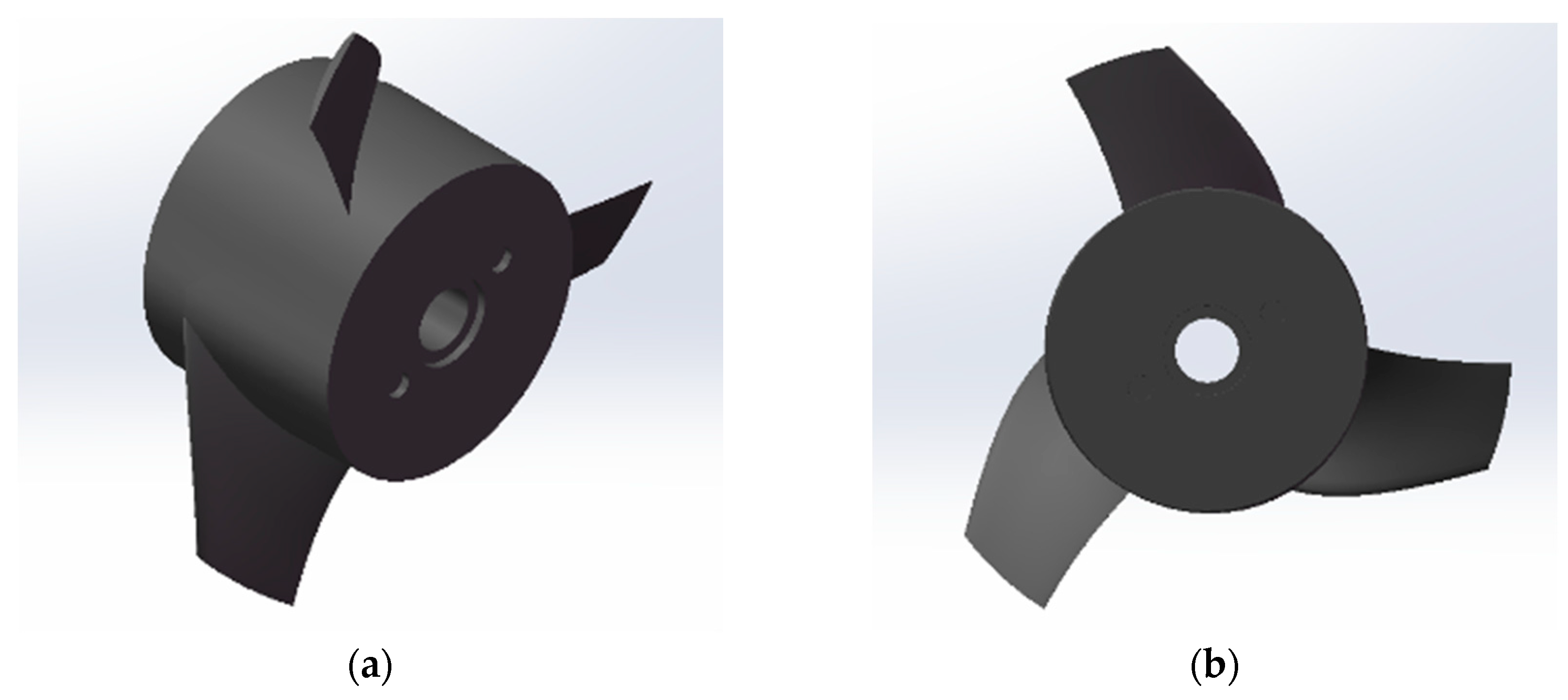
At present, the propeller used in the AUH is a three-blade propeller independently developed by the team. Its three-dimensional view is shown in Figure 13. The maximum diameter is approximately 76 mm and a maximum thrust of 5 kg can be generated at a rotation speed of 3800 rpm.
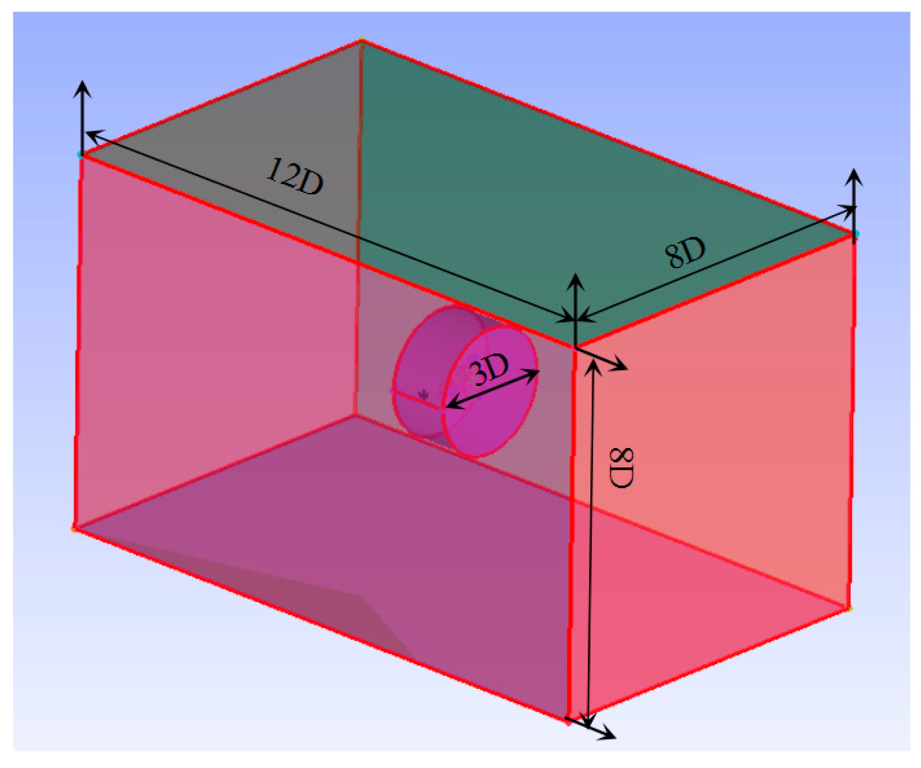
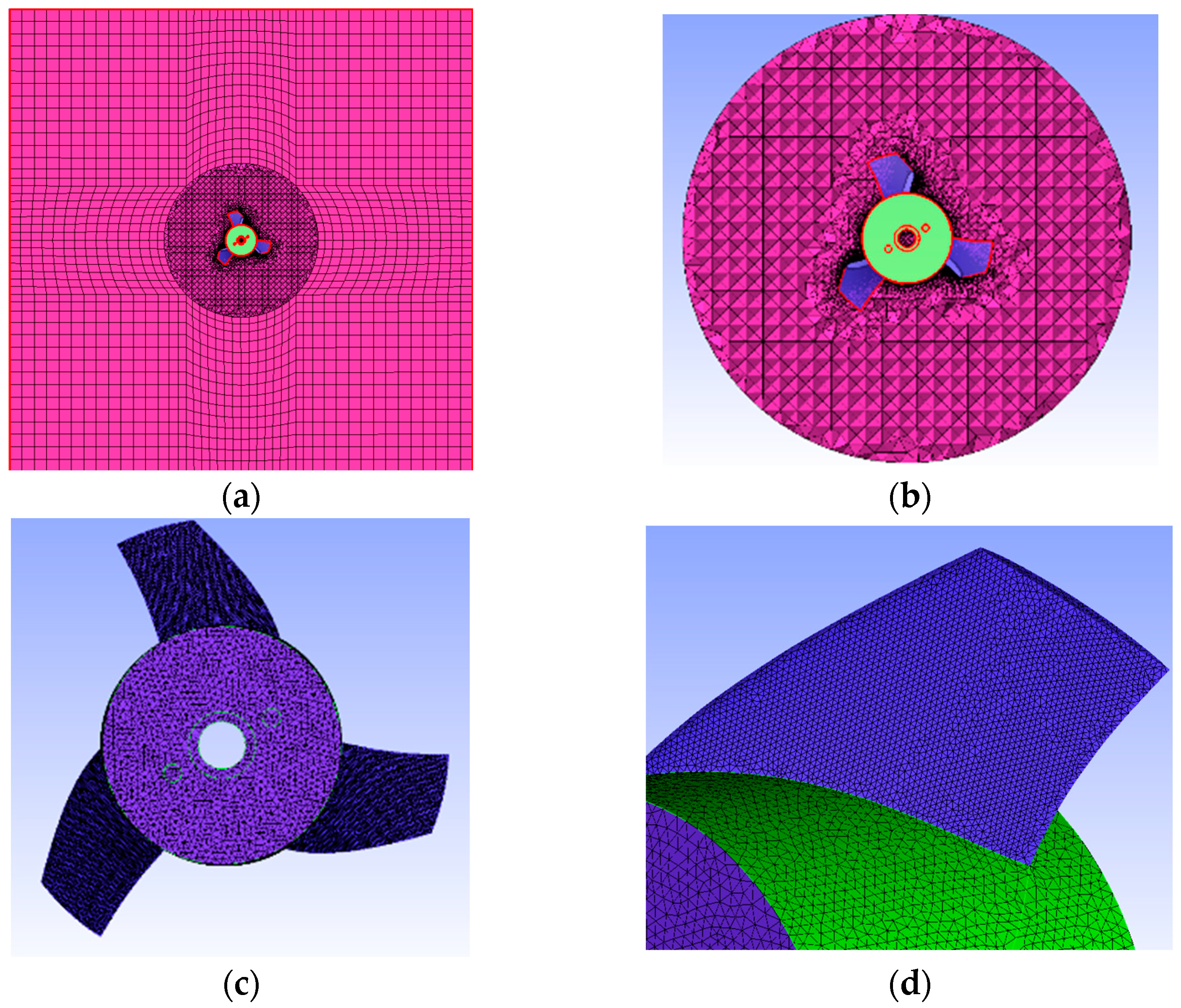
The meshing of the propeller adopts the sliding grid technology and is mainly divided into the stationary domain and the rotational domain. As shown in Figure 14, the two computing domains are connected through the interface.
The cylindrical calculation domain is the rotational calculation domain, and the outer cuboid is the stationary calculation domain. The diameter of the rotational calculation domain is 3D, and the length, width, and height of the static calculation domain are, respectively, 12D, 8D, and 8D, where D is the maximum propeller diameter. The mesh is shown in Figure 15.

5.2. Hydrodynamic Performance of the Propeller

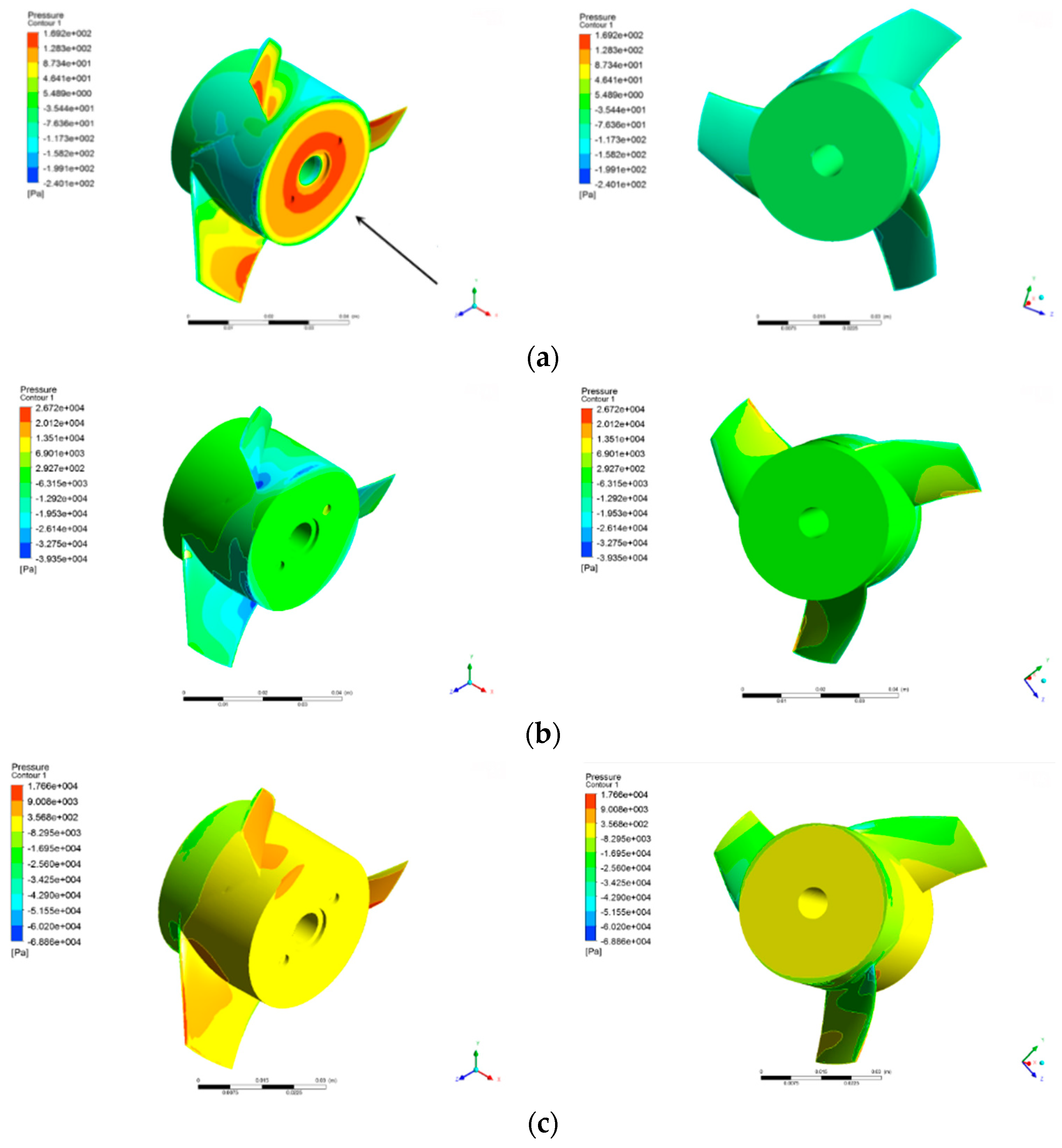
The pressure distributions at different rotating speeds are shown in Figure 16. It can be seen that when the rotating speed is positive, the pressure on the back of the propeller blade is greater than the pressure on the front surface of the blade, which will generate a force to propel the propeller forward. When the rotating speed is negative, the pressure on the back of the propeller blade is less than the pressure on the front surface of the blade. The force generated by the propeller is opposite to the forward direction of the AUH. The direction of the rotating speed is judged by the right-hand rule. The motion coordinate system of the propeller is parallel to the AUH’s motion coordinate system.
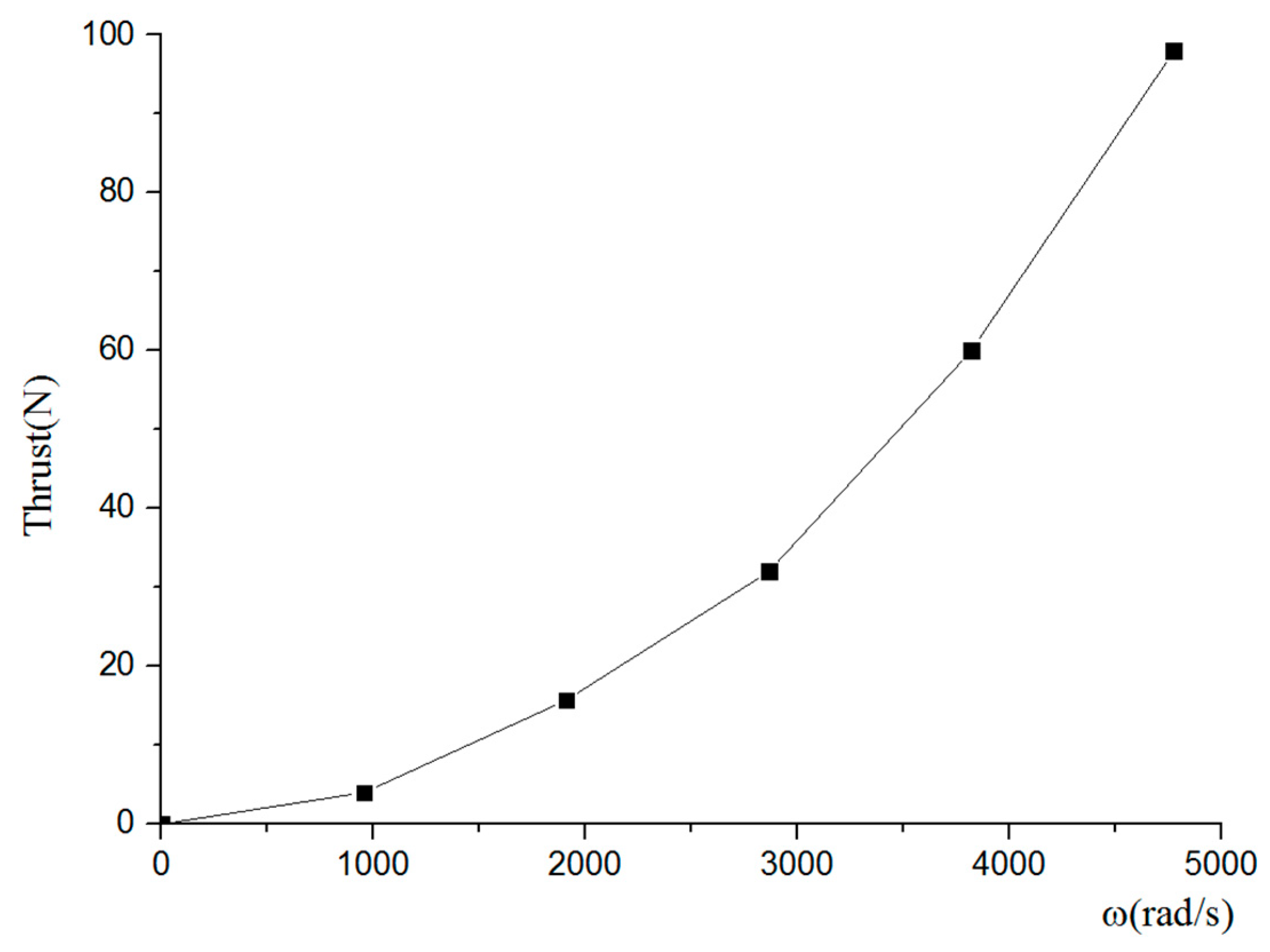
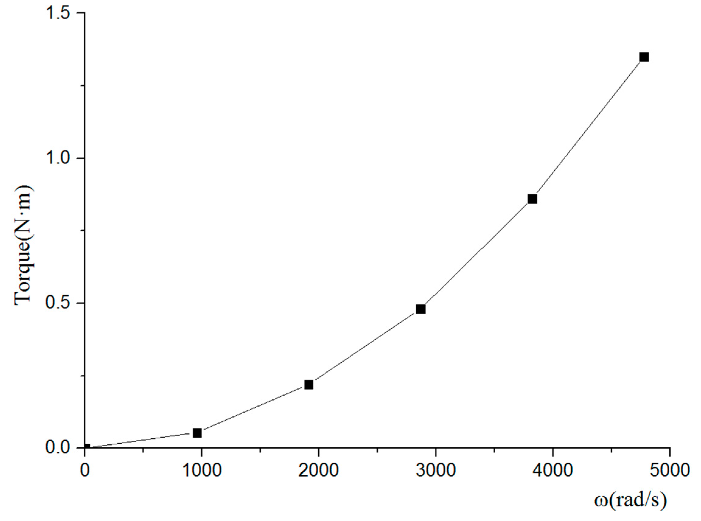
The curves of thrust and torque of the propeller with rotating speed are shown in Figure 17 and Figure 18; generally, when studying the hydrodynamic performance of the propeller, the absolute values of thrust and torque are not used but they are expressed as a non-dimensional coefficient, such as thrust coefficients, KT, torque coefficients, KQ, efficiency, ƞ, and advance ratio, J, as follows:
K T = T ρ n 2 D 4
K Q = Q ρ n 2 D 5
η = T V a 2 π n Q = K T ρ n 2 D 4 V a 2 π n K Q ρ n 2 D 5 = K T K Q V a 2 π n D = K T K Q J 2 π
J = V a n D
K T J 2 = T ρ n 2 D 4 / V a 2 n 2 D 2 = T ρ D 2 V a 2 = R ρ D 2 V a 2 0.9 = E H P ρ D 2 V a 3 0.9 = 2.12
where T denotes the thrust produced by the propeller, Q denotes the torque of the propeller, Va denotes the velocity of the currents, n denotes the rotating speed of the propeller, and D is the propeller diameter.
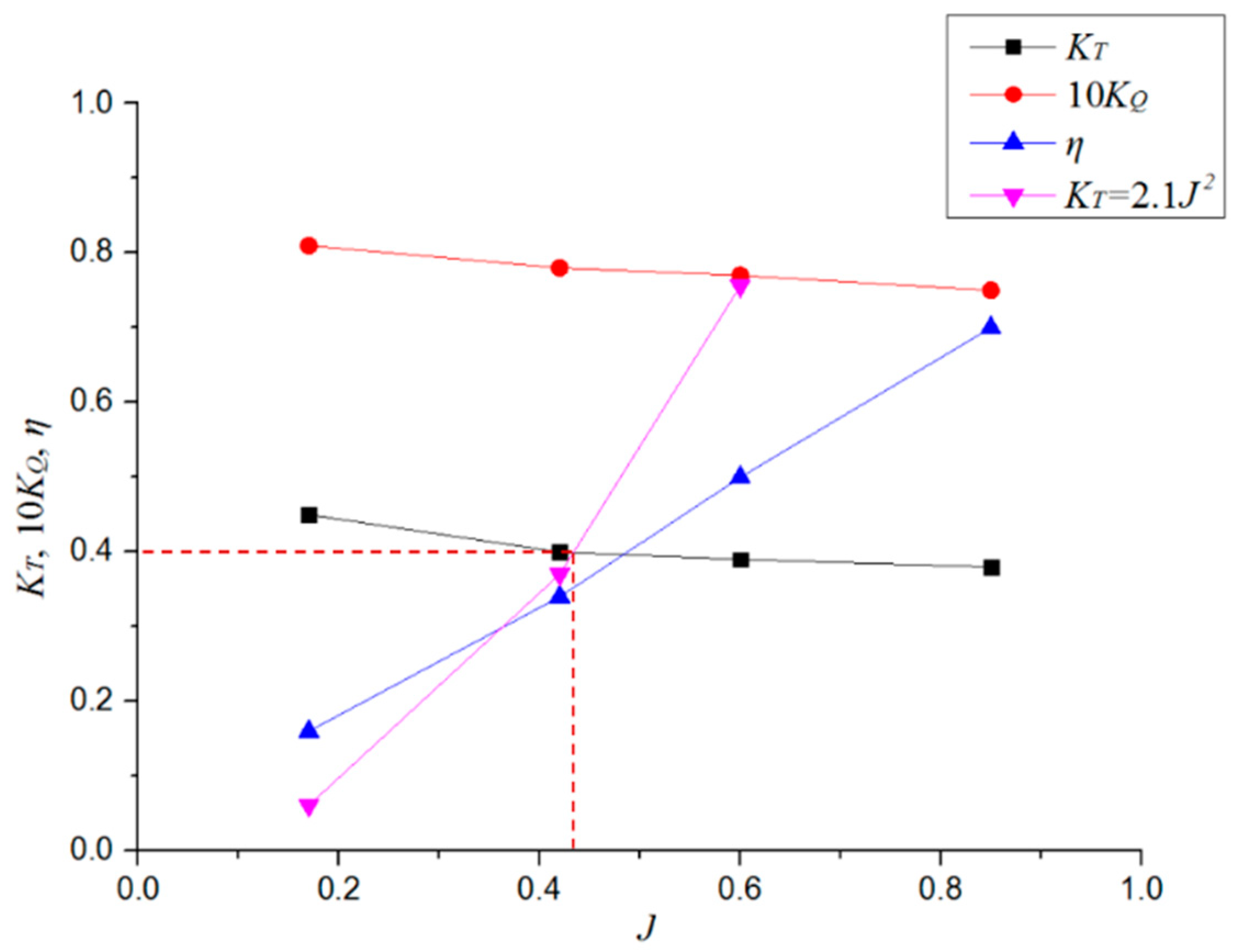
Because the AUH can only carry limited energy, the estimate of the power of the AUH is very important. From the AUH resistance, propeller thrust, effective horsepower, speed, and propeller diameter, as in Equations (5), (8) and (10), and the curve of the KT ratio to J2 as in Equation (9) was obtained, i.e., the propeller loading coefficient, which presents the AUH propeller thrust per unit area of the propeller plane in this study. Hence, the intersection point between the curve of KT and the curve of KT about J2 is the value of the advance ratio J that the propeller is working on the AUH. The intersection of the two lines is a suitable mechanical power energy-saving matching point, as shown in Figure 19.
Figure 19 shows that the point of intersection is at J = 0.43, i.e., the matching point between the AUV and the propeller, and the open water efficiency of the propeller is about 0.38. In this paper, the open water efficiency is approximated as the propeller propulsion efficiency. Thus, we can obtain the energy-saving propeller revolution to provide thrust for the AUH for the analysis of energy consumption of the AUH escaping from currents in the next section.

6. A Comparison Using Three Different Methods to Escape Currents

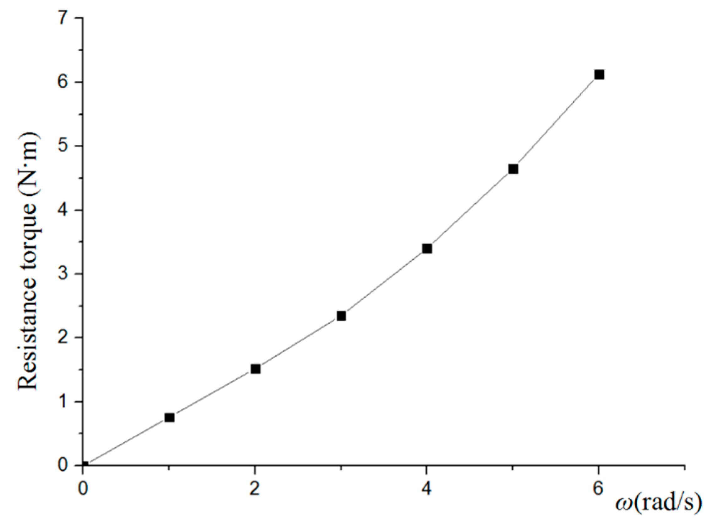
Besides escaping currents by rotating motion, the AUH also can move laterally or vertically by using the acting propellers. In order to prove that the rotating motion can help the AUH to escape from the currents more effectively, this study analyzed the velocity with different methods used to escape the currents. When the inflow velocity was 2 knots, the resistance torque of the AUH changed with the rotating speed, as shown in Figure 20. Because the hull structure of the AUH is a disk-shaped structure with a smooth surface, its resistance torque is small. When all three methods were used to escape from currents, the curves of the required force generated by the propeller changes with the escape velocity are as shown in Figure 21.
Figure 21 shows that for the AUH to rise vertically to escape from the currents, the propeller needs to generate a large force due to its dish shape. Contrary to this kind of motion, the AUH escaping from the currents by using the Magnus force produced by rotating motion of the AUH only needs a small force produced by the propeller. If the AUH adjusts the direction of movement to escape from the currents, the driving force produced by the propeller is also small, but it is obviously larger than the rotating motion.
Because the AUH can only carry limited energy, for the AUH to meet the required design speeds and voyages, the resistance during navigation, battery, and efficiency of the propeller will play a very important role. The battery carried by the AUH can fully discharge 5.76 × 10⁵ J of energy.
The voyage of the AUH can be obtained according to Equation (10) [5]:
R a n g e = E v / 1000 ( P P + P H )
where E (J) is the energy of the battery stored in the AUH, v (m/s) is the velocity of the AUH, Pp (W) is the required power of the propeller, and PH (W) is the power of the system and sensors required for payload operation.
The curves of resistance as a function of the velocity of the AUH are shown in Figure 21. According to Equation (11), the effective horsepower of the AUH, i.e., the power to overcome the resistance, can be obtained:
E H P = R × v
where the EHP is the effective horsepower of the AUH, R denotes the AUH resistance, and v is the AUH velocity.
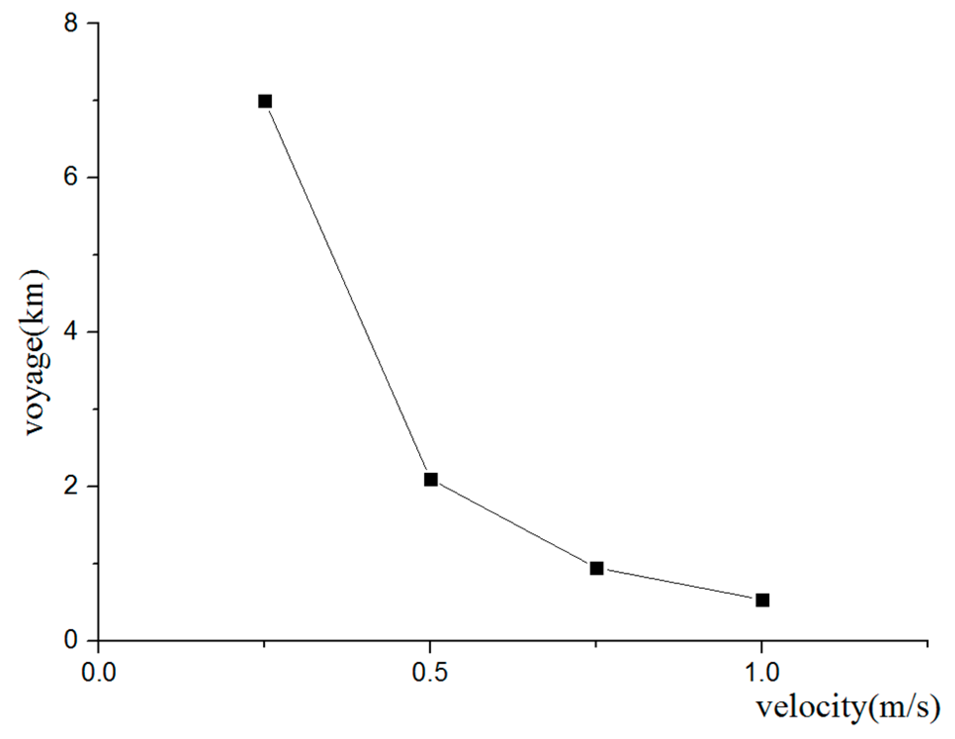
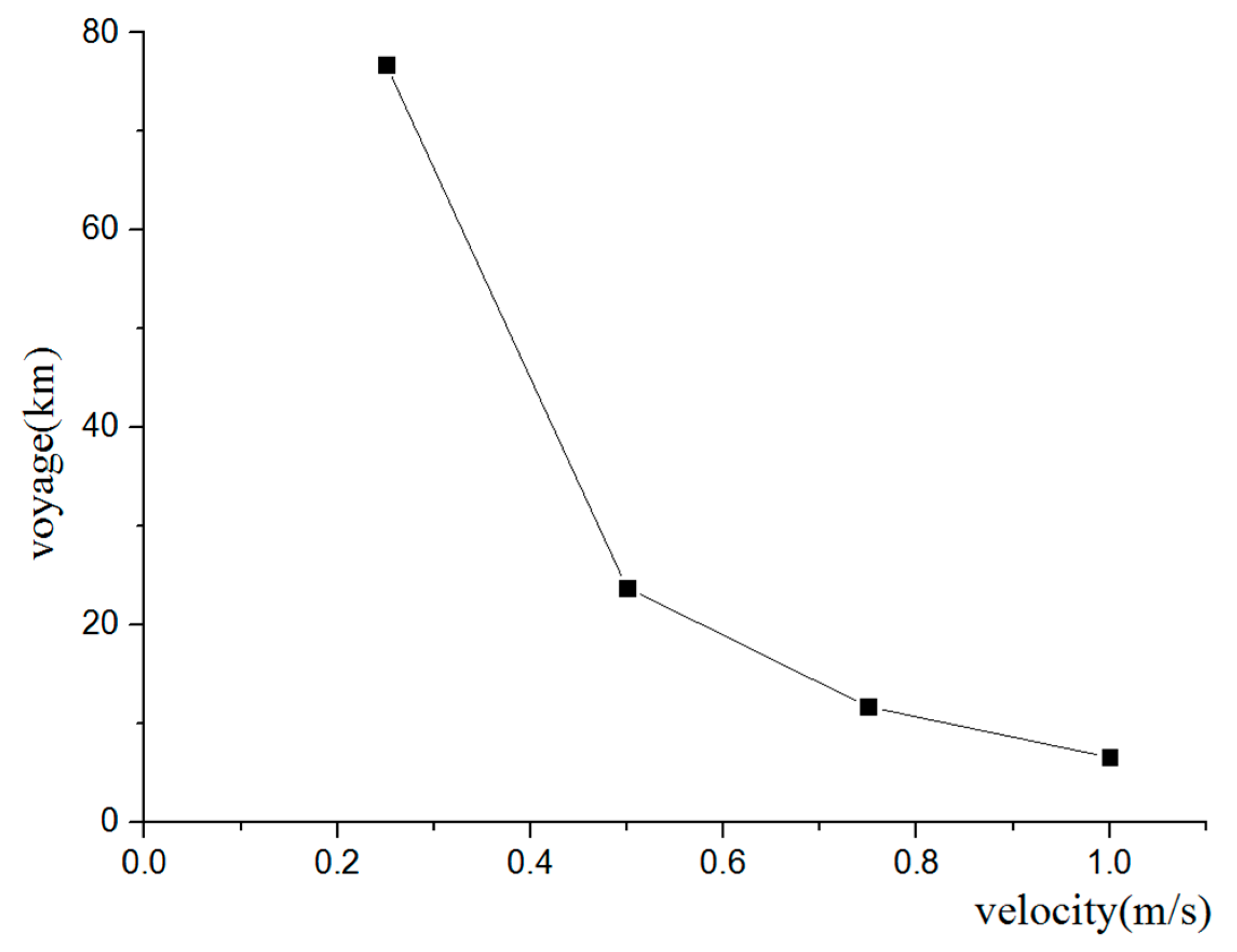
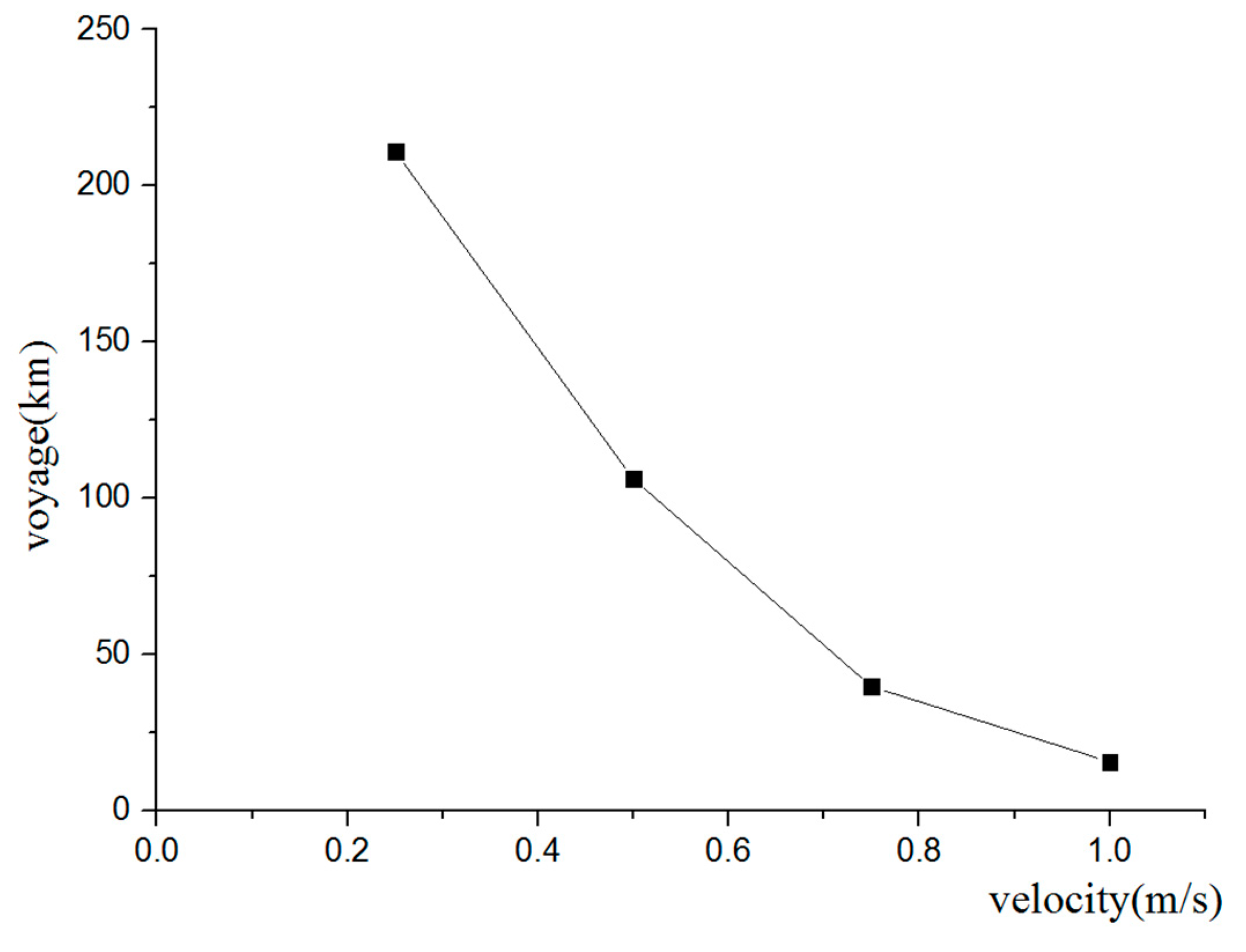
Assuming no consideration of other energy losses, the voyage of the AUH at different velocities can be obtained according to Equations (10) and (11), as shown in Figure 22, Figure 23 and Figure 24, and the related values are provided in Table 3. For the rotating motion, the calculation of the voyage needs to take into account the relationship between rotating speed and navigation velocity and calculate the sailing time of the underwater helicopter according to Equation (10) and the rotating speed.
In Table 3, the simulation results show that the voyage of the AUH decreases as the navigation velocity increases. The maximum voyages of the AUH when escaping from currents using the three different methods are 7 km (rising in the vertical plane), 78 km (moving laterally in the horizontal plane), and 211 km (relying on the Magnus force). The first two methods directly push the AUH out of the disturbance zone using propeller thrust. Obviously, relying on Magnus force to allow the AUH to escape from the currents (using the third method) results in the largest voyage. The main factor that causes this phenomenon is that the AUH’s escaping motion is mainly dependent on the Magnus force instead of the thrust of the propeller when the AUH is rotating around its z axis in yaw, and its hull has minimal resistance at the same escaping velocity; thus, the driving force produced by the propeller is very small and effectively saves battery energy.

7. Conclusions

The hydrodynamic performance of an axis-symmetric, disk-shaped AUH in uniform flow conditions and the propulsion performance of a high-speed propeller were analyzed using the ANSYS-CFX RANS solver. CFD prediction of the variations in the hydrodynamic Magnus force coefficients of the spinning AUH in the horizontal plane versus the spin ratio was carried out successfully, and the induced Magnus effects were observed clearly. The Magnus force was generated by the AUH’s spinning behavior with a proper spinning speed, whereas this force would be close to zero without the spinning behavior. These force coefficients increase proportionally to the spin ratio, but the increase of the force slows as the spin ratio increases. A propeller loading coefficient integrated with the AUH resistance and configurated propeller thrust was formulated and predicted using the CFD method to estimate energy-saving propeller revolution to advance the AUH escaping from the disturbance area. A comparison of the proposed method and two conventional methods used to promote the AUH escaping from currents was carried out. Obviously, the Magnus force can be more efficient in driving the AUH escape from the current zone as compared to using the propellers directly to drive the AUH escape from the spoiler zone. Hence, the proposed anti-flow method for the AUH can be an effective and efficient problem-solving method while the inflow direction and the yz plane of the AUH body-fixed coordinate system are orthogonal. The Magnus force is an effective force to drive AUVs away from a uniform ocean current region and is recommended for future research and practical applications, including effects of vertical and/or diagonal water flows on the AUH which should be considered and the development of a high-performance attitude controller for the AUH experimental verification.

Author Contributions

C.-W.C. contributed the concept and methodology; C.-W.C. and Y.J. performed the numerical simulation, data curation and visualization; C.-W.C. and Y.J. performed the formal analysis; C.-W.C. and Y.J. wrote the original draft; C.W.C. wrote the review.

Funding

This research was funded by [the national key special research plan of the China Ministry of Education], [the National Natural Science Foundation of China] and [Zhoushan Science and Technology Project] grant number [2017YFC0306100], [51409230] and [2018C81041].

Acknowledgments

The authors wish to thank the national key special research plan of the China Ministry of Education and the National Natural Science Foundation of China for their financial support of this research under the project grant numbers 2017YFC0306100 and 51409230. C.W. Chen thanks Zhoushan Science and Technology Project, grant number 2018C81041. The authors are grateful to the anonymous reviewers for their valuable comments in improving the paper. The authors thank to Zhou Y. for providing the disk-type AUV 3-D model.

Conflicts of Interest

The authors declare no conflict of interest.

References

  1. Evans, J.; Nahon, M. Dynamics modeling and performance evaluation of an autonomous underwater vehicle. Ocean Eng. 2004, 31, 1835–1858. [Google Scholar] [CrossRef] [Green Version]
  2. Pyo, J.; Cho, H.; Joe, H.; Ura, T.; Yu, S.C. Development of hovering type AUV “Cyclops” and its performance evaluation using image mosaicing. Ocean Eng. 2015, 109, 517–530. [Google Scholar] [CrossRef] [Green Version]
  3. Phillips, A.; Furlong, M.; Turnock, S.R. The Use of Computational Fluid Dynamics to Determine the Dynamic Stability of an Autonomous Underwater Vehicle. 2007. Available online: https://core.ac.uk/download/pdf/28341.pdf?repositoryId=34 (accessed on 18 March 2018).
  4. Lapierre, L.; Soetanto, D. Nonlinear path-following control of an AUV. Ocean Eng. 2008, 33, 89–102. [Google Scholar] [CrossRef]
  5. Phillips, A.B.; Turnock, S.R.; Furlong, M. The use of computational fluid dynamics to aid cost-effective hydrodynamic design of autonomous underwater vehicles. Proc. Inst. Mech. Eng. Part M J. Eng. Mar. Environ. 2010, 224, 239–254. [Google Scholar] [CrossRef]
  6. Chen, C.W.; Jiang, Y.; Huang, H.C.; Ji, D.X.; Sun, G.Q.; Yu, Z.; Chen, Y. Computational fluid dynamics study of the motion stability of an autonomous underwater helicopter. Ocean Eng. 2017, 143, 227–239. [Google Scholar] [CrossRef]
  7. Minnick, L.M. A Parametric Model for Predicting Submarine Dynamic Stability in Early Stage Design; Virginia Tech: Blacksburg, VA, USA, 2006. [Google Scholar]
  8. Tanakitkorn, K.; Wilson, P.A.; Turnock, S.R.; Phillips, A.B. Depth control for an over-actuated, hover-capable autonomous underwater vehicle with experimental verification. Mechatronics 2017, 41, 67–81. [Google Scholar] [CrossRef] [Green Version]
  9. Lin, X.; Guo, S. Development of a Spherical Underwater Robot Equipped with Multiple Vectored Water-Jet-Based Thrusters. J. Intell. Robot. Syst. 2012, 67, 307–321. [Google Scholar] [CrossRef]
  10. Ba, X.; Luo, X.; Shi, Z.; Zhu, Y. A vectored water jet propulsion method for autonomous underwater vehicles. Ocean Eng. 2013, 74, 133–140. [Google Scholar]
  11. Chen, C.W.; Jiang, Y.; Huang, C.H.; Leng, J.X.; Yu, Z.; Su, H.; Chen, Y. Computational Fluid Dynamics Study on Magnus Force of an Autonomous Underwater Helicopter. In Proceedings of the OCEANS 2017, Anchorage, AK, USA, 18–21 September 2017; pp. 1–6. [Google Scholar]
  12. Kray, T.; Franke, J.; Frank, W. Magnus effect on a rotating sphere at high Reynolds numbers. J. Wind Eng. Ind. Aerodyn. 2012, 110, 1–9. [Google Scholar] [CrossRef]
  13. Yang, C.; Peng, S.; Fan, S.; Zhang, S.; Wang, P.; Chen, Y. Study on docking guidance algorithm for hybrid underwater glider in currents. Ocean Eng. 2016, 125, 170–181. [Google Scholar] [CrossRef]
  14. Chen, C.W.; Kouh, J.S.; Tsai, J.F. Maneuvering Modeling and Simulation of AUV Dynamic Systems with Euler-Rodriguez Quaternion Method. China Ocean Eng. Int. J. 2013, 27, 403–416. [Google Scholar] [CrossRef]
  15. Chen, C.W.; Kouh, J.S.; Tsai, J.F. Modeling and Simulation of an AUV Simulator with Guidance System. IEEE J. Ocean. Eng. 2013, 38, 211–225. [Google Scholar] [CrossRef]
  16. Bettle, M.C.; Gerber, A.G.; Watt, G.D. Using reduced hydrodynamic models to accelerate the predictor–corrector convergence of implicit 6-DOF URANS submarine maneuvering simulations. Comput. Fluids 2014, 102, 215–236. [Google Scholar] [CrossRef]
  17. Bettle, M.C.; Gerber, A.G.; Watt, G.D. Unsteady analysis of the six DOF motion of a buoyantly rising submarine. Comput. Fluids 2009, 38, 1833–1849. [Google Scholar] [CrossRef]
  18. CFX. Innovative Turbulence Modeling: SST Model in ANSYS CFX. 2006. Available online: https://support.ansys.com/staticassets/ANSYS/staticassets/resourcelibrary/techbrief/cfx-sst.pdf (accessed on 18 March 2018).
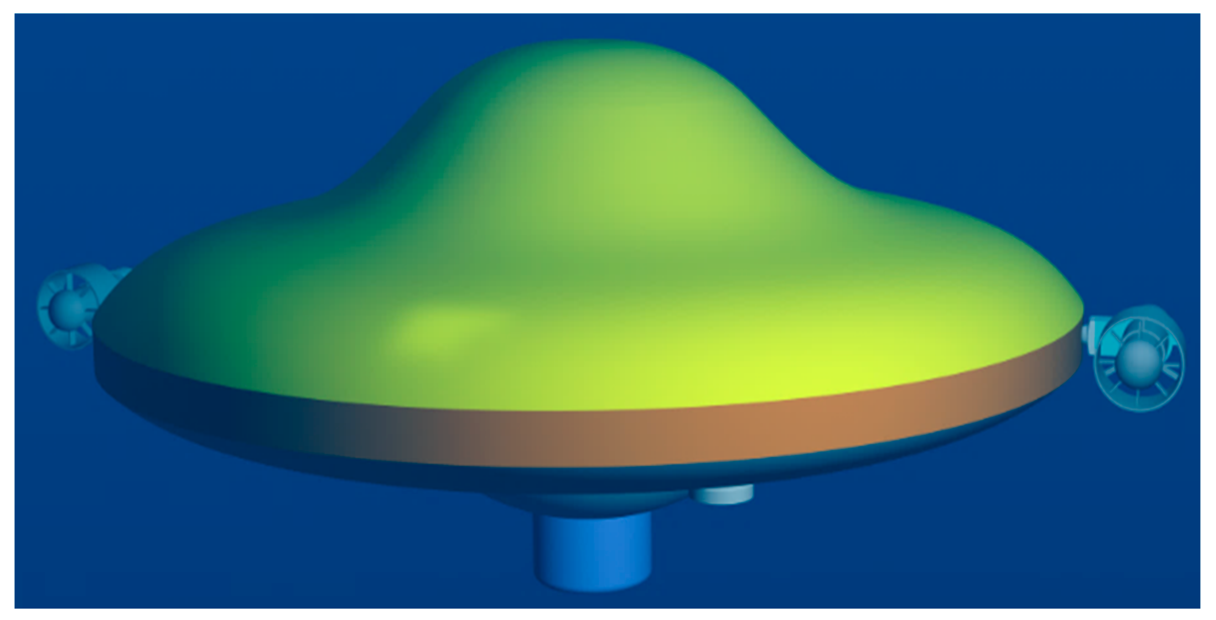
Figure 1. The structural design of the autonomous underwater helicopter (AUH).
Symmetry 11 00397 g001
Figure 2. The AUH prototype mounted with vectoring propellers for the underwater experiment.
Symmetry 11 00397 g002
Figure 3. The working model of the AUH from seabed to seabed.
Symmetry 11 00397 g003
Figure 4. The AUH coordinate systems.
Symmetry 11 00397 g004
Figure 5. The mesh types in the computational fluid domain: (a) Boundary layer thickness; (b) sliding meshes in a cuboid computational fluid domain.
Symmetry 11 00397 g005
Figure 6. The computational fluid domain used to simulate turbulent flow over the spinning AUH and the computational fluid dynamics (CFD) meshing results.
Symmetry 11 00397 g006
Figure 7. The boundary conditions for the spinning AUH: (a) Top view in the xz plane; (b) side view in the xy plane.
Symmetry 11 00397 g007
Figure 8. Streamlines produced by ANSYS-CFX CFD calculations of turbulent flow over the AUH with spin ratios of 0 and 5.83, using both the k–ε and shear stress transport (SST) k–ω turbulence models.
Symmetry 11 00397 g008
Figure 9. Pressure distribution of the AUH hull form with spin ratios of 0 and 5.83, using both the k–ε and SST k–ω turbulence models.
Symmetry 11 00397 g009
Figure 10. Variations in Magnus force and drag for different spinning speeds with inflow velocities of 1 and 2 knots.
Symmetry 11 00397 g010
Figure 11. The variation of drag with an inflow velocity of 1 knot and Magnus force with an inflow velocity of 2 knots as spinning speed increases.
Symmetry 11 00397 g011
Figure 12. The curve of escaping velocity of the AUH relative to rotating speed.
Symmetry 11 00397 g012
Figure 13. The propeller used in the AUH: (a) The perspective view; (b) the front view.
Symmetry 11 00397 g013
Figure 14. Computational domain.
Symmetry 11 00397 g014
Figure 15. The CFD meshes of the propeller: (a) The sliding mesh technology applied to the propeller surface meshed around a hexahedron-mesh static computing domain; (b) the tetrahedral mesh generated around the propeller surface in the rotational computing domain; (c) the front view on the tetrahedral mesh around the propeller; (d) the perspective view on the tetrahedral meshes of the blade and hub surfaces.
Symmetry 11 00397 g015
Figure 16. The pressure distribution of propellers at different rotating speeds: (a) 0 rpm; (b) 1900 rpm; (c) −1900 rpm.
Symmetry 11 00397 g016
Figure 17. The thrust of the propeller changing with rotating speed.
Symmetry 11 00397 g017
Figure 18. The torque of the propeller changing with rotating speed.
Symmetry 11 00397 g018
Figure 19. The curves of the hydrodynamic performance of the propeller.
Symmetry 11 00397 g019
Figure 20. The resistance torque of the AUH changing with the rotating speed.
Symmetry 11 00397 g020
Figure 21. The driving force produced by the propeller that the AUH requires to escape currents.
Symmetry 11 00397 g021
Figure 22. The relationship between voyage and velocity during vertical motion.
Symmetry 11 00397 g022
Figure 23. The relationship between voyage and velocity during horizontal motion.
Symmetry 11 00397 g023
Figure 24. The relationship between voyage and velocity during rotating motion.
Symmetry 11 00397 g024
Table 1. The design parameters of the AUH.
Design ParametersSymbolPhysical UnitValue
DiameterLm1.0
Design depthhm0–1000
HeightHm0.43–0.48
Massmkg50–150
Design velocityVkn1
Center of gravityG(xG, yG, zG)mm(0, 0, 0)
Center of buoyancyB(xB, yB, zB)mm(0, 0, −39.5)
Table 2. Computational parameters applied to the spinning AUH CFD simulation.
ParametersSetting
Computing performance4 Intel Xeon CPUs, 72 cores, 36 threads, 2.1 GHz, 256 GB of RAM
No. of meshing elements2.05 million
Mesh typeStructured, sliding meshes
Turbulence modelsk–ε, k–ω (SST)
Advection schemeANSYS-CFX high resolution
Residual convergenceRMS residual < 10–5
Notes: SST—shear stress transport.
Table 3. The relationship between voyage and velocity of the AUH while escaping currents.
Voyage (km)
Velocity (m/s)Method 1 (Figure 21)
Vertical Motion Model
Method 2 (Figure 22)
Lateral Motion Model
Proposed Method 3 (Figure 23)
Rotating Motion Model
0.25778211
0.52.123.8106.2
0.750.9511.753
10.546.627.4