1. Introduction
Foam concrete is a lightweight cellular concrete made of cement, fly ash, and other ingredients, with physically or chemically added foam into the slurry in the reaction process, widely applied in civil engineering such as thermal isolation of buildings and non-load bearing roofs and floors. Due to its high porosity and cellular structure similar to metallic foams, foam concrete exhibits a long stress plateau with increasing strain subjected to compression and may absorb a considerable amount of energy, making it a promising material for protection of buildings and structures. As core of the potentially applied sacrificial claddings attached to building exterior, the foam concrete undergoes large deformation when subjected to blast or impact load, reducing the load transferred to the protected structure to an acceptable level, which can be tuned by designing the strength of cement and relative density of foam concrete.
The static or quasi-static performance of foam concrete was extensively examined e.g., [
1]. Nambiar et al. [
2,
3], Kearsley and Wainwright [
4], and Kramer et al. [
5] obtained a number of data and results in terms of the manufacturing and property characterization of foam concrete. However, the dynamic property of foam concrete is not well studied and only little research was reported, probably due to its limited applications subjected to dynamic load in the past. Zhao et al. [
6] investigated the protection of foam concrete layer in tunnel as sacrificial cladding, and found that the protection with a reasonable design against an internal explosion is effective.
In terms of energy absorption, it is found that adding polypropylene fibers and husk ash cannot significantly improve the energy absorption capacity of foam concrete [
7,
8]. In a low velocity impact test, Jones et al. [
9] investigated the energy absorption of foam concrete of density 500–1400 kg/m
3 with different mixing ratios, and revealed that specific energy absorption of foam concrete reaches its maximum with density 1000 kg/m
3 and water–cement ratio of 0.6–0.7, in a range of 5 to 14 MJ/m
3. Nevertheless, the energy absorption capacity of foam concrete in different literature cannot be compared as the mixing ratios, additives, and densities are different.
Some researchers have numerically studied honeycombs response subjected to dynamic in-plane compression. Ruan et al. simulated different response modes of aluminum honeycombs with commercial package ABAQUS [
10]. Two-dimensional aluminum honeycomb models with cell size 2.7 mm and thickness 0.08 mm to 0.5 mm were established to approximately represent aluminum foam, with which the dynamic response subjected to in-plane compression was numerically simulated. A rigid plate was used to crush the honeycomb with varying velocity. With the same approach, the effect of strength gradient of aluminum honeycombs on response modes subjected to different velocity in-plane crushing was investigated with LS-DYNA [
11].
In fact, the micro-structure of the foam concrete is three-dimensional, while the honeycomb model is two-dimensional in a plane stress manner. Therefore, although the size and shape of the honeycomb approximately resemble those of the foam concrete, the constraint from the adjacent part is different. In other words, the two-dimensional honeycomb model cannot fully represent the three-dimensional micro-structure of real foam concrete. To this end, there is no experimental data to validate this kind of numerical model. However, it is believed that the response modes and energy absorption characteristics of foam concrete can be approximately represented by honeycomb model, although the specific value of energy absorption may not make sense [
10,
11].
In the present study, concrete honeycomb is employed to represent the micro-structure of foam concrete, with which the response and energy absorption subjected to dynamic compression is investigated. The finite element method is not suitable for the current simulation since concrete is brittle and will be smashed into a huge number of pieces during the crushing process. To this end, smoothed particle hydrodynamics (SPH) is adopted to simulate the response. With major dynamic response modes revealed, the critical velocity is determined, followed by the relationship between the loading speed and shock front velocity in high velocity crushing mode, as well as the energy absorption capacity, which facilitates the dynamic property characterization and application of foam concrete.
2. Smoothed Particle Hydrodynamics
The Lagrangian method is advantageous over the Eulerian method in terms of accuracy of capturing the deformation of materials, as the mesh moves together with the materials. However, due to this feature, large deformation will distort the mesh, leading to reduced computational accuracy and even error and stop of computation. Instead, the SPH method, as a meshless method based on the Lagrangian approach, can be considered a modified Lagrangian method combining the merits of high accuracy of the Lagrangian method and a mesh-free feature, and is thus adopted in the present study.
By nature, SPH method is a kind of interpolation, with which a function
f(
x) can be approximately represented by the integral of interpolation of a group of disordered points in the neighborhood:
where <
f(
x)> is the approximation of
f(
x),
x is displacement vector, Ω is an object containing
x,
W(
x −
x′,
h) is the smoothing function depending on the displacement between two points and smoothing length
h, usually chosen as third order spline kernel function [
12]:
where
,
,
for one-, two- and three-dimensional space, respectively.
.
The smoothing function is pivotal in determining the accuracy and efficiency of computation, which should satisfy three conditions as follows. First, the normalization condition stating that the integral should be equal to unity:
Second, the smoothing function becomes a Dirac function with smoothing length approaching zero:
where
Third, the condition of compact support:
where
k is constant for the effective support domain of the smoothing function at Point
x.
Combining integral by part and divergence theorem, the derivative of function
f(
x) is approximately estimated as:
where
i and
j are number of particles,
mi and
ρi are mass and density of particle
i.
N is the total particle number.
3. Numerical Model
Foam concrete is a cellular solid with tiny pores of a large volume fraction. The average pore size of typical foam concrete is significantly smaller than that of metallic foams. In fact, cellular solid can be considered as a special structure of the base material from which it is made. It is widely accepted that micro-structure-based models more accurately represent their behavior than the macro-structure-based homogenized model, if static or dynamic deformation is of concern. To capture the response of such cellular solid at the same time being computationally effective, the honeycomb model and Voronoi model are frequently employed to study the aluminum foam subjected to compression of various loading speeds [
10,
11]. The response of aluminum foam was intensively and extensively examined with these models. However, the micro-structure model of foam concrete with the honeycomb or Voronoi approach are not yet reported to date. Therefore, in the current study, foam concrete is similarly idealized as the honeycomb model.
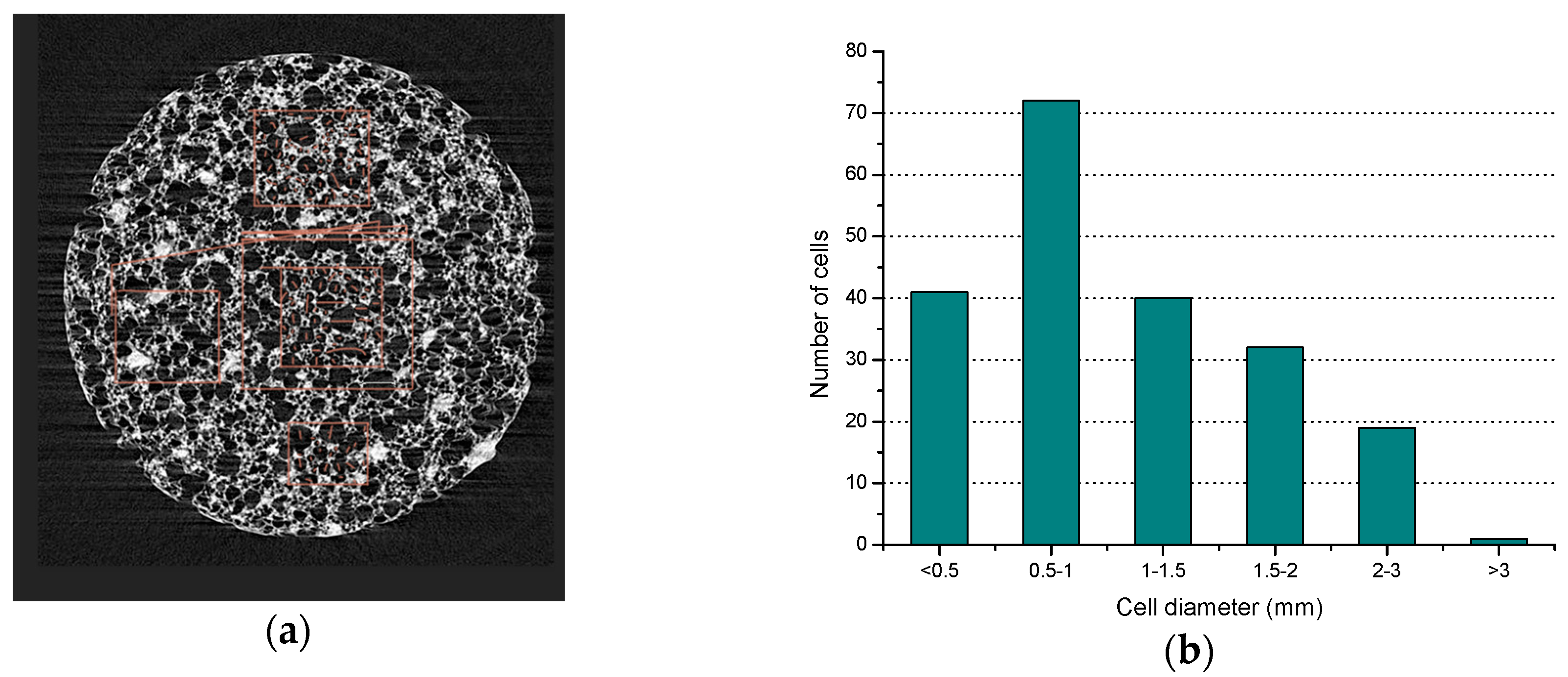
We have CT scanned some foam concrete samples and carried out reconstruction, one of which is shown in
Figure 1a. The statistics of the cell size distribution is shown in
Figure 1b.
To approximately represent the micro-structure of foam concrete, the size of the uniform hexagonal honeycomb is chosen as 0.5 mm. Then, the cell wall thickness can be determined to model different porosities (0.846, 0.792, 0.75, 0.667, 0.593). For example, the porosity of 0.846 results in wall thickness 0.07 mm.
As shown in
Figure 2a, a honeycomb comprised of staggered arranged hexagons of edge length 0.5 mm is established, in which there are 9 horizontal cells and 20 vertical cells, respectively. The in-plane wall thickness throughout the model is 0.07 mm, leading to a relative density of the honeycomb of 0.154 and porosity of 0.846. The model is established in LS-DYNA then imported to AUTODYN for calculation in SPH method. The material is plain concrete of 35 MPa uni-axial compressive strength. By nature, the model is two-dimensional. However, to facilitate the computation in SPH, the out-of-plane thickness is set as one particle size. Particle size sensitivity study is conducted and the particle size is chosen as 0.015 mm to balance accuracy and computational time. The out-of-plane velocity of all particles is set as zero to ensure the honeycomb to deform in-plane. A steel plate of dimension 7 mm wide and 2 mm high and out-of-plane size 0.015 mm impacts the honeycomb in a constant speed from 1 to 40 m/s, while the bottom line of the honeycomb remains stationary at all times. The contact between the plates and honeycomb is set as automatic in AUTODYN.
As the computational time to simulate the dynamic crushing response of the honeycomb with the model in
Figure 2a is too long, a smaller but similar honeycomb model with 7 horizontal cells and 12 vertical cells is established while each cell is the same as that in
Figure 2a, shown in
Figure 2b. Similarly, two steel plates of 5.5 mm and 0.5 mm in-plane and 0.015 mm out-of-plane sandwich the honeycomb. Different from the model in
Figure 2a simulating the dynamic response, in
Figure 2b, while the lower plate remains stationary, the upper plate crushes the honeycomb with an initial velocity, rather than a constant speed. With some rounds of trial computations, the initial speed of the upper plate for energy absorption study is set as 2 to 7 m/s.
The properties of concrete and steel are summarized in
Table 1.
4. Results and Discussions
The SPH method takes significantly longer computational time than Lagrangian method. Eight Xeon CPUs of 2.4 GHz each were used and it takes approximately 168 h for the larger model in
Figure 2a and 96 h for the smaller model in
Figure 2b.
4.1. Dynamic Response and Critical Velocity
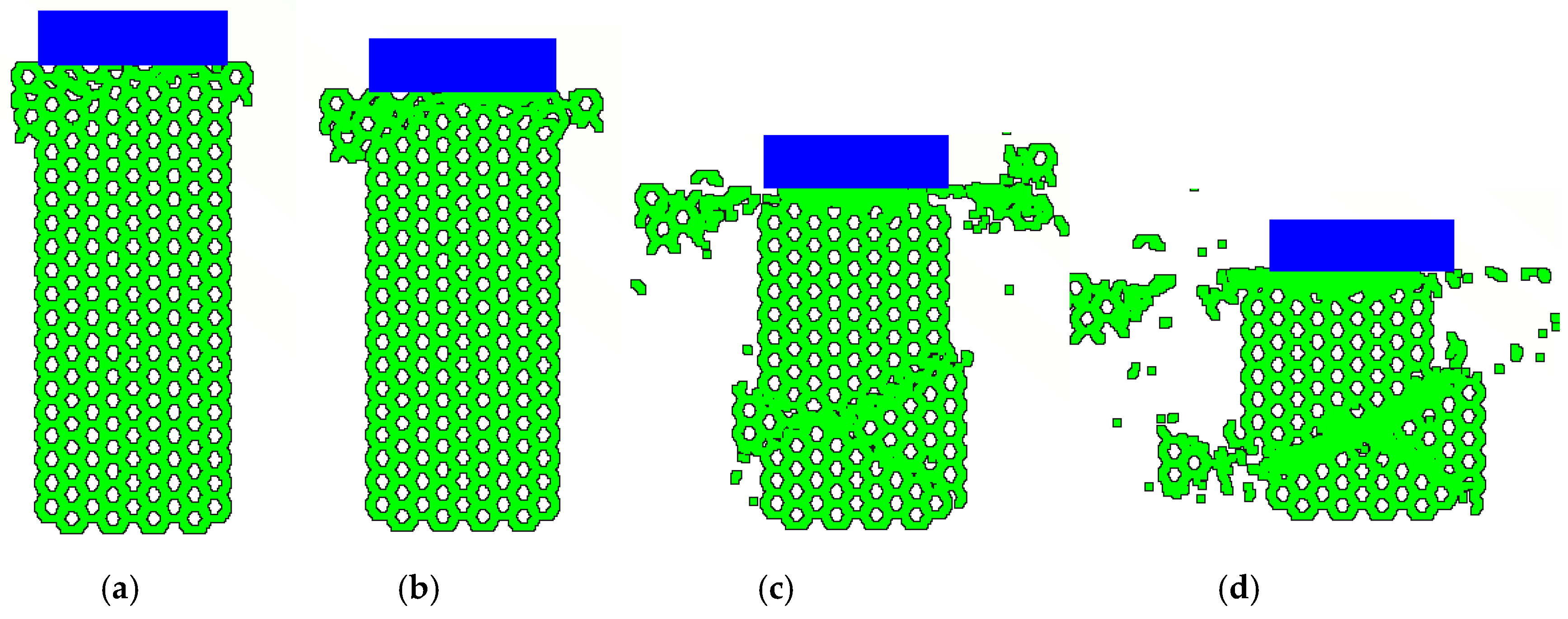
Subjected to dynamic crushing of different speed, the honeycomb exhibits remarkably different response modes. When the crushing speed is relatively low, i.e., 1 m/s, initially, the corners of the honeycomb part adjacent to the impacting plate shear off, forming a V-shaped deformation zone, as shown in
Figure 3b. Due to the effect of stress wave propagation within the honeycomb, an X-shaped shear failure takes places near the fixed end, shown in
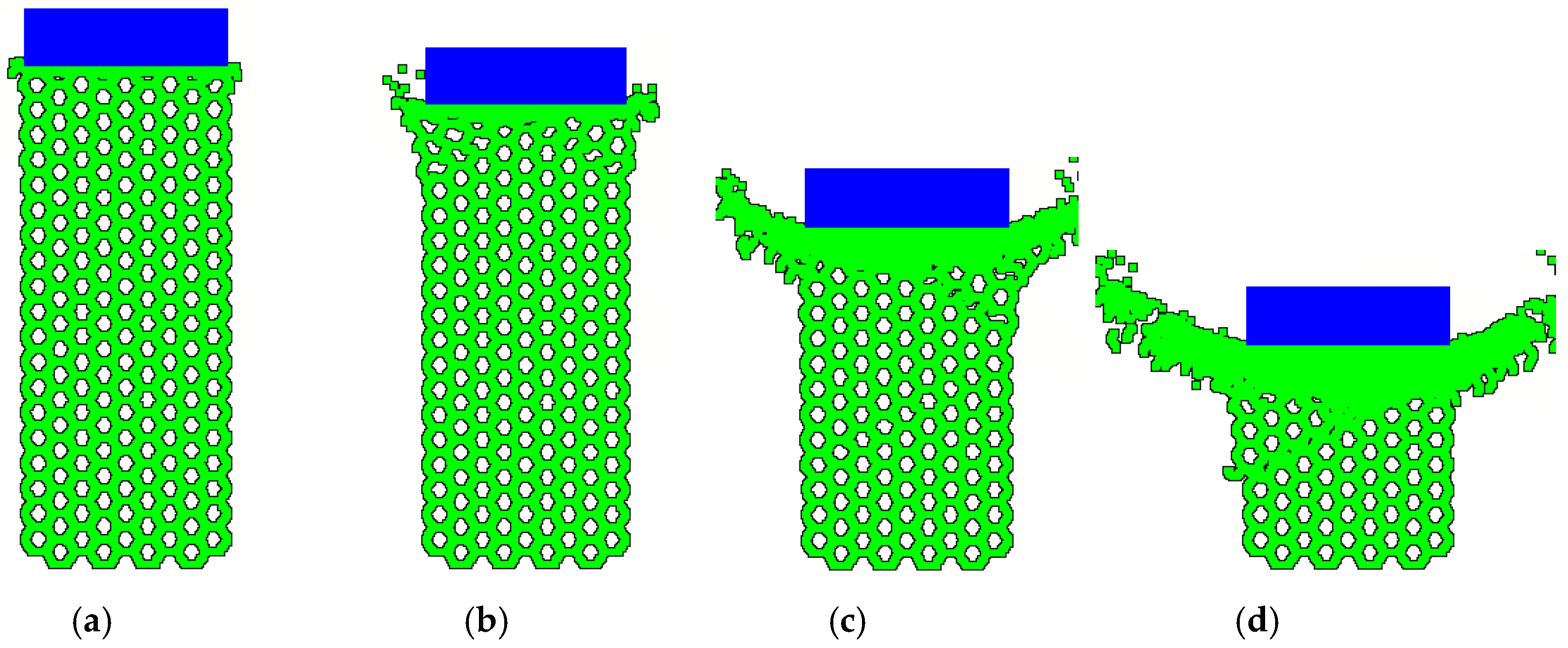
Figure 3c. When subjected to higher crushing speed, i.e., 18 m/s, the honeycomb undergoes a mixed dynamic deformation mode: the shear failure near the impacting end occurs but is not obvious. At the same time, an I-shaped crushing near the impacting end appears which means there is no shear and the crushing is one-dimensional, shown in
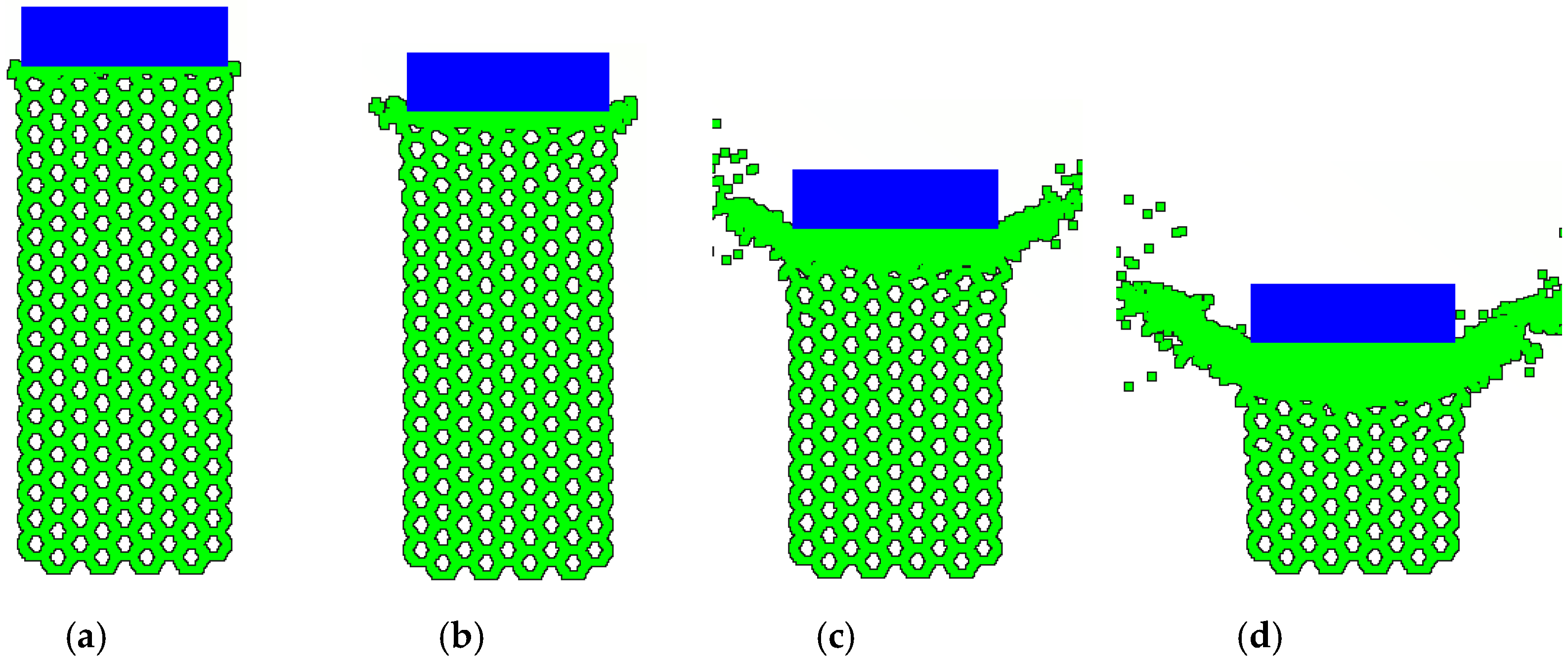
Figure 4b. The combined mode sometimes can be termed as K mode. With increasing compression speed, i.e., 40 m/s, shear failure completely disappears and I-shaped crushing mode dominates the whole response, shown in
Figure 5.
Analysis suggests that the concrete honeycomb exhibits different response modes. With increasing loading velocity, it undergoes V mode, to K mode, finally to I mode. In fact, K mode can be considered as the combination of the low velocity response V mode and the high velocity response I mode, when the honeycomb is subjected to compression in intermediate speed. This is in fact a transitional stage between the low-speed and high-speed crushing. While these modes more or less resemble those of aluminum foam under dynamic crushing with different velocity, the difference is also obvious: the concrete honeycomb experiences detached parts rather than the sheared but attached parts in aluminum foam.
The critical velocity is an important parameter for cellular solids. Consider a cellular solid subjected to compression with varying loading rate. If the compression speed is low, the deformation of the cellular solid will initiate either from the weak part (for cellular solids with obvious defects) or response uniformly throughout the entire solid (for cellular solids without obvious defects). However, if the compression speed is high, the cellular solid responds in a progressive collapse manner, which means the part near the loading end is fully crushed while the part near the stationary end remains elastic deformation (not crushed at all). The loading velocity separating two response modes is termed as ‘critical velocity’.
In addition to the case of 1 m/s, 18 m/s, and 40 m/s mentioned above, a series of other simulations are done to determine the range of critical velocity. It is from more simulation cases that for the present honeycomb configuration and concrete material, the critical velocity is in the range between 25 m/s and 40 m/s, beyond which the honeycomb undergoes progressive collapse mode from the impacting end. With plate speed higher than the critical velocity, there exists a shock front separating the densified and undeformed parts. It must be noteworthy that the critical velocity is for the concrete foam with this particular porosity, cell size, wall thickness, and concrete property. However, the critical velocity of other concrete honeycombs can be obtained with the same method.
4.2. Energy Absorption
A concern on the dynamic behavior of foam concrete is its energy absorption capacity, which is important in determining whether foam concrete is suitable for sandwich core to dissipate dynamic energy. Consider the system consisting of the impacting plate and the concrete honeycomb. At time zero, the total energy of the system is the kinetic energy of the impacting plate, as the honeycomb is at rest and undeformed. At any time instant of the loading process, the total energy is conserved, provided that there is no external force doing work. The crushing, or the interaction between the impacting plate and the honeycomb, transforms part of the plate kinetic energy to internal energy (in LS-DYNA, the internal energy is defined as total energy minus the kinetic energy) and kinetic energy of the honeycomb, together with the work of concrete foam fractures. At the time when the plate speed becomes zero, the total energy of the system is the internal energy, kinetic energy of the honeycomb. The energy loss in honeycomb is due to the fractures. In the present study, the combination of internal energy and fracture energy of honeycomb is defined as the energy absorption by the honeycomb.
Figure 6 shows the energy absorption capacity of the concrete honeycomb of porosity 0.846 increases with increasing initial loading velocity, with initial plate impacting speed ranging from 2–7 m/s.
If the plate impacting velocity is fixed at 7 m/s, the energy absorption capacity of different porosity (e.g., 0.846, 0.792, 0.75, 0.667, 0.593) is examined and shown in
Figure 7. As expected, the higher the porosity, the lower the specific energy absorption.
4.3. Shock Front Velocity
It is well established in the research of metallic foam dynamic crushing that the relationship between the loading speed and the shock front velocity as:
where
vs is the velocity of the shock front propagating in the cellular solid.
V is the impacting plate speed and
εD is the densification strain.
Figure 8 shows the relationship between the shock front speed and impacting velocity, which is a constant. It is seen that the gradient of the line is almost a constant, suggesting that the relationship is linear within the range of impacting velocity 1–15 m/s, which implies that the relationship is valid in cellular solid, no matter the foam is made of ductile or brittle material.
4.4. Limitations
In fact, the concrete honeycomb may not fully represent foam concrete, especially when it comes to the non-uniformity. To more reasonably delineate the non-uniformity and defects resulted from manufacturing process, the Voronoi-based model may be used to account for the micro-structure. Furthermore, with the aid of CT scanning, numerical models accounting for real micro-structure can be established, facilitating accurate numerical simulation of foam concrete subjected to various loads. However, the computation will be remarkably expensive than the current study, which will be carried out in the future.


