Article

Research on Nonlinear Coupling Anti-Swing Control Method of Double Pendulum Gantry Crane Based on Improved Energy

1
School of Mechanical Engineering, Shenyang Jianzhu University, Shenyang 110168, China
2
School of Control Science and Engineering, Shandong University, Jinan 250061, China
3
The State Key Laboratory of Rolling and Automation, Northeastern University, Shenyang 110819, China
*
Author to whom correspondence should be addressed.
Symmetry 2019, 11(12), 1511; https://doi.org/10.3390/sym11121511
Submission received: 21 October 2019 / Revised: 4 December 2019 / Accepted: 10 December 2019 / Published: 12 December 2019

Abstract

:
The double pendulum type gantry crane is a typical symmetry underactuated motion system. It has control problems in that the swing of the payload is difficult to suppress and the precise positioning of the trolley is not accurate. A new nonlinear coupling control method based on improved energy is proposed in this paper. We define coupled control signal among trolley, hook and payload. An improved energy storage function is established based on the new coupling control signal. Consequently, a nonlinear anti-swing controller is constructed straightforwardly, and the closed-loop system stability is subject to strict mathematics analysis by Lyapunov and LaSalle’ s theorem. Moreover, the new energy function based on the coupling behaving between the trolley motion and the payload swing leads to the improved control performance. Numerical simulation results show that the proposed method has better performance than traditional controllers. It not only effectively suppresses the swing of the load and the hook, but also precisely controls the displacement of the trolley. It has strong robustness to the displacement of the payload, the change of the gantry crane parameters and the external disturbance.

1. Introduction

The gantry crane is a kind of common engineering equipment used in construction, port logistics, manufacturing and other fields [1,2]. The main goal of the gantry crane control system is not only to move the payload from its initial position to the desired position accurately, but also to quickly suppress and eliminate the swing of the payload throughout the process. In addition, the number of system degrees of freedom greater than the number of control inputs is referred to as the symmetry underactuated system [3]. Gantry cranes are typical representatives of symmetry underactuated systems. Among different types of nonlinear underactuated control systems [4,5,6,7], there are many unsolved challenges in gantry crane control.
Currently, most gantry cranes are operated manually. Therefore, work efficiency is heavily dependent on the proficiency of the operator. We all know that manual manipulation is generally inefficient and inaccurate. Inadvertent incorrect operation can even lead to serious accidents. Therefore, it is very important to suppress the swing angles of the payload and improve the positioning errors of the trolley. The safety and efficiency of the gantry crane system has attracted much attention from researchers and has obtained many useful and constructive advanced control methods, such as trajectory planning-based control [8,9,10], inversion control [11], adaptive control [12,13,14], nested control [15], energy control [16,17,18], intelligent control [19,20,21,22], feedback linearization control [23], delay-based control [24,25], gain scheduled control [26], sliding mode control [27,28,29], prediction control [30,31,32], advanced robust control [33,34] etc.
The control method mentioned above treats the payload swing as a swing of a single pendulum. The hook and payload are roughly considered to be the same mass point, or the hook is directly ignored. However, this is obviously unreasonable because the payload is usually suspended from the hook by a long steel cable. The payload and hook cannot simply be considered the same mass point. This is the double pendulum phenomenon in which the hook swings around the trolley and the payload swings around the hook (See Figure 1). When the gantry crane exhibits the double-pendulum phenomenon, it is very difficult to suppress or eliminate the hook swing and payload swing, even for experienced operators. In addition, most control methods based on single-pendulum gantry cranes are not suitable for this situation. So far, research on nonlinear control for gantry crane with double pendulum swing effect is still in its early days and has some unsolved problems.
Some proportional derivative (PD) controller and passivity-based controller are proposed in [35,36] by analyzing the underactuated and passivity characteristics of the gantry crane. However, these two controllers have very poor suppression performance of payload swing due to the lack of feedback on the payload and hook motion. In order to improve the control performance of the double pendulum gantry crane, conventional sliding mode control (CSMC) method [37] and fuzzy control method [38] based on the single input-rule modules have been designed for the gantry crane with double pendulum effects. In addition, Sun N et al. suggested a new quasi-proportional integral derivative controller [39] and a model-based nonlinear anti-swing controller [40] to effectively control underactuated double-pendulum crane systems. However, these control methods need to get the system parameters of the double pendulum gantry crane, such as the payload mass, cable length, desired positions et al. It is obviously unrealistic. Because different payloads have different masses, different cables lengths, and different desired positions. These system parameters cannot be known before the transportation process begins. Moreover, Zhang M et al. proposed a novel energy coupling based controller [41] and an enhanced coupling proportional derivative with sliding mode controller [42] for the double pendulum gantry crane. Some robust and online trajectory planning methods are presented in [43,44], respectively. However, these feedback controllers are proposed under complex structures and are difficult to use in actual double-pendulum gantry cranes. Therefore, the above-mentioned controller has three main problems: weaker swing suppression control performance, depending on precise system parameters and complex structures that cannot be practically applied.
To solve the above problems, we propose a nonlinear anti-swing control law for the gantry crane with double-pendulum swing effects and uncertain parameters, which can achieve effective control for both trolley position and swing suppression/elimination. Then, the origin of the closed-loop system stability analysis is presented by using the Lyapunov techniques and LaSalle’s invariance theorem. Lastly, several groups of simulations are implemented to demonstrate the proposed controller’ actual performance. Briefly, the main contributions of this paper are presented as follows:
(1). The proposed nonlinear anti-swing control law is designed based on shaped energy function of double-pendulum gantry cranes. The defined generalized signals including trolley motion, hook swing and payload swing increase the state coupling of the system, so the control performance is improved compared to the traditional feedback controllers.
(2). There are no system parameters in the proposed control method. This means that even if some physical parameters (for example, hook and payload masses and lengths of cable) are uncertain or unknown, the control performance will not be seriously affected. For the proposed control method, it is not necessary to know the system parameters of the gantry crane.
(3). The control method proposed in this paper is useful in the actual gantry crane system because it has a simpler structure than the other traditional closed-loop feedback controllers.
(4). The proposed method controller is robust to uncertain transfer distances, uncertain model parameters and various external disturbances.
The rest of this article is organized as follows. Section 2 describes the dynamic model of underactuated double pendulum gantry crane. Then, the control law development and stability analysis are carried out in Section 3. After that, Section 4 provides some numerical simulation results that demonstrate the effectiveness of the control scheme. Lastly, the conclusion of this paper is presented in Section 5.

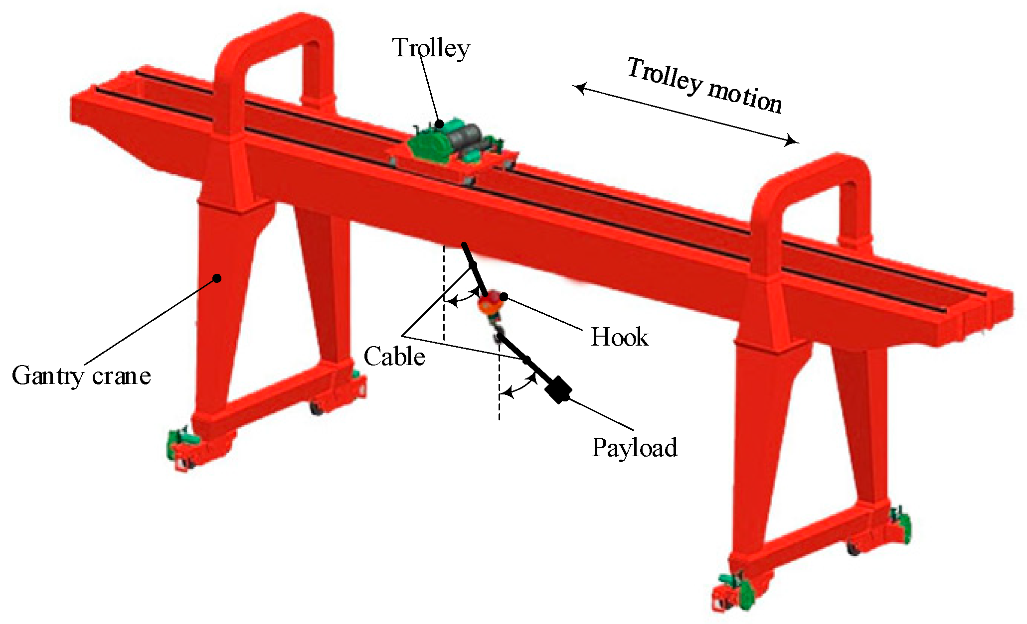
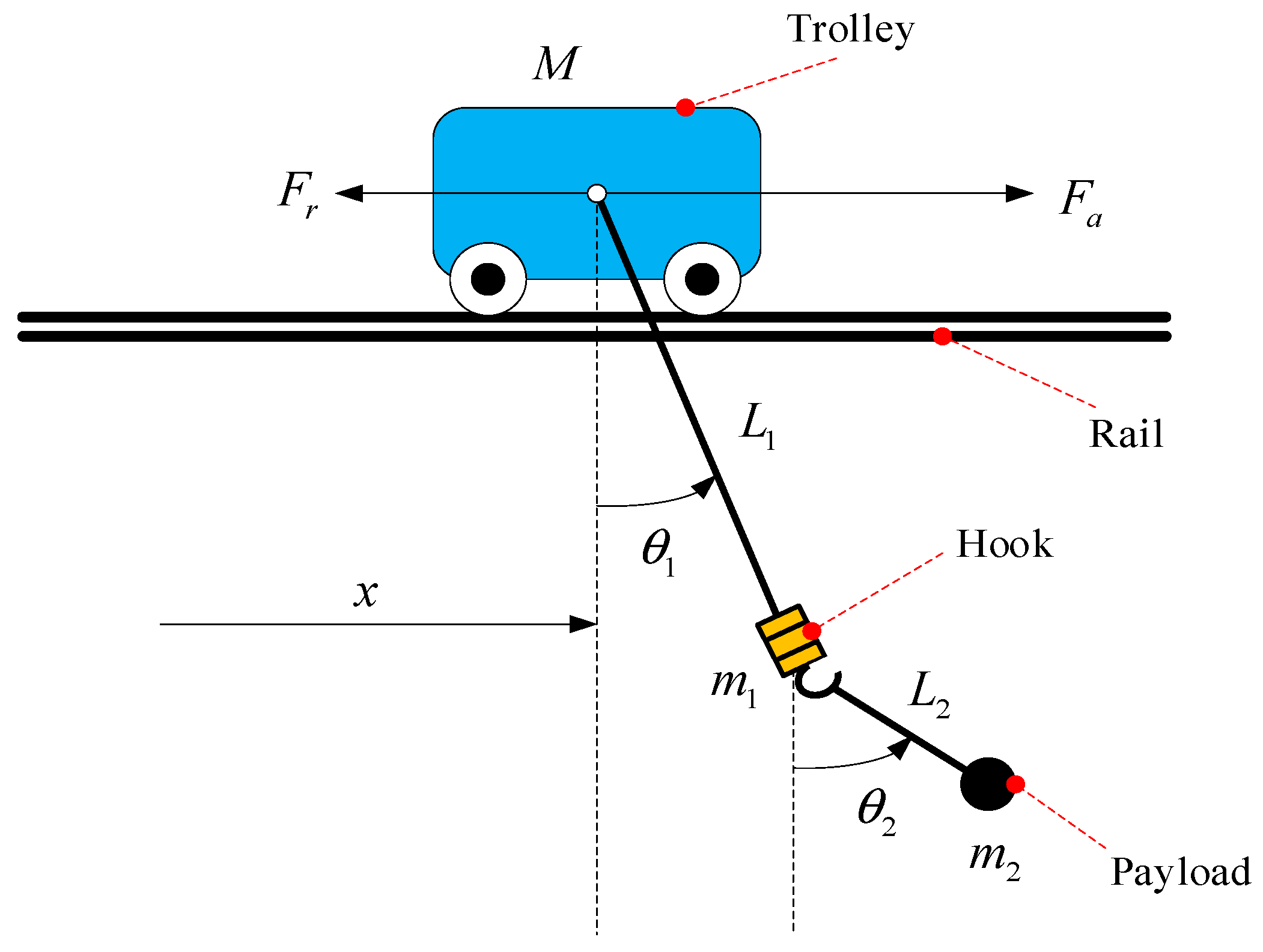
2. Dynamics of Gantry Crane with Double-Pendulum

The schematic diagram of the gantry crane with double-pendulum is shown in Figure 2. In the case of ignoring the air resistance, the Euler-Lagrange equation is used to establish the dynamic model of the double pendulum gantry crane [39,40,41,42]:
M ( q ) q ¨ + V m ( q , q ˙ ) q ˙ + G ( q ) = U
where q refers to the gantry crane system state vector; M ( q ) refers to the gantry crane system inertia matrix; V m ( q , q ˙ ) refers to the gantry crane system centripetal-Coriolis force matrix; G ( q ) refers to the gantry crane system gravitational potential energy vector; U refers to the gantry crane system control vector. The above parameters are specifically defined as follows:
q = [ x ( t ) θ 1 ( t ) θ 2 ( t ) ] T
M ( q ) = [ M + m 1 + m 2 ( m 1 + m 2 ) l 1 cos θ 1 m 2 l 2 cos θ 2 ( m 1 + m 2 ) l 1 cos θ 1 ( m 1 + m 2 ) l 1 2 m 2 l 1 l 2 cos ( θ 1 θ 2 ) m 2 l 2 cos θ 2 m 2 l 1 l 2 cos ( θ 1 θ 2 ) m 2 l 2 2 ]
V m ( q , q ˙ ) = [ 0 ( m 1 + m 2 ) l 1 θ ˙ 1 sin θ 1 m 2 l 2 θ ˙ 2 sin θ 2 0 0 m 2 l 1 l 2 θ ˙ 2 sin ( θ 1 θ 2 ) 0 m 2 l 1 l 2 θ ˙ 2 sin ( θ 1 θ 2 ) 0 ]
G ( q ) = [ 0 ( m 1 + m 2 ) g l 1 sin θ 1 m 2 g l 2 sin θ 2 ] T
U = [ F 0 0 ] T
where M , m 1 and m 2 represent the trolley mass, the hook mass and the payload mass, respectively; l 1 and l 2 denote the cable length and the distance of the payload point-mass from the hook point-mass; x is the displacement of the trolley; θ 1 refers to the swing angle of the hook; θ 2 stands for the payload swing angle; g represents the acceleration of gravity; F stands for the resultant force applied to the trolley, which consists of the following two parts:
F = F a F r
where F a denote the actuating force of the trolley; Nonlinear mechanical friction force F r between the trolley and the rail can be described as [39,40,41,42]:
F r ( x ˙ ) = f r 0 tanh ( x ˙ / ξ ) k r | x ˙ | x ˙
where f r 0 and ξ represent static friction-related coefficients, and k r denotes a viscous friction-related parameter.
Equation (1) is rewritten to facilitate the development of the following controllers:
( M + m 1 + m 2 ) x ¨ + ( m 1 + m 2 ) l 1 ( θ ¨ 1 cos θ 1 θ ˙ 1 2 sin θ 1 ) + m 2 l 2 θ ¨ 2 cos θ 2 m 2 l 2 θ ˙ 2 2 sin θ 2 = F
( m 1 + m 2 ) l 1 cos θ 1 x ¨ + ( m 1 + m 2 ) l 1 2 θ ¨ 1 + m 2 l 1 l 2 cos ( θ 1 θ 2 ) θ ¨ 2 + m 2 l 1 l 2 sin ( θ 1 θ 2 ) θ ˙ 2 2 + ( m 1 + m 2 ) g l 1 sin θ 1 = 0
m 2 l 2 cos θ 2 x ¨ + m 2 l 1 l 2 cos ( θ 1 θ 2 ) θ ¨ 1 + m 2 l 2 2 θ ¨ 2 m 2 l 1 l 2 sin ( θ 1 θ 2 ) θ ˙ 1 2 + m 2 g l 2 sin θ 2 = 0
As can be seen from Figure 1, x p ( t ) is the payload horizontal displacement:
x p = x + l 1 sin θ 1 + l 2 sin θ 2
Herein, we define the generalized payload horizontal displacement signal X p based on the form of (12):
X p = x + k a 1 sin θ 1 + k a 2 sin θ 2
where k a 1 , k a 2 R + are yet to be adjusted parameters. The generalized payload horizontal displacement X p is a natural coupling signal. It can help to increase the coupling behavior among trolley translation x ( t ) , the hook swing θ 1 ( t ) and the payload swing θ 2 ( t ) . Therefore, X p is the basis of the double pendulum gantry crane nonlinear coupling anti-swing controller development. The following assumptions are made without loss of generality.
Assumption 1.
The cable is massless and inflexible. In addition, the length of the cable remains constant during the transferring process and the twisting of the cable can be ignored.
Assumption 2.
The payload is always below the trolley during the overall transferring process.
The mathematical expression is as follows:
π 2 < θ 1 , θ 2 < π 2 , t 0

3. Main Results

This section describes the controller design and the stability analysis. First, the nonlinear coupling anti-swing controller has been designed based on the improved energy storage function for gantry crane with double-pendulum swing effects. Then, the stability of the closed-loop system is proven by Lyapunov techniques and LaSalle’s invariance theorem. The block diagram is provided in Figure 3 to make the controller design and stability analysis clear.

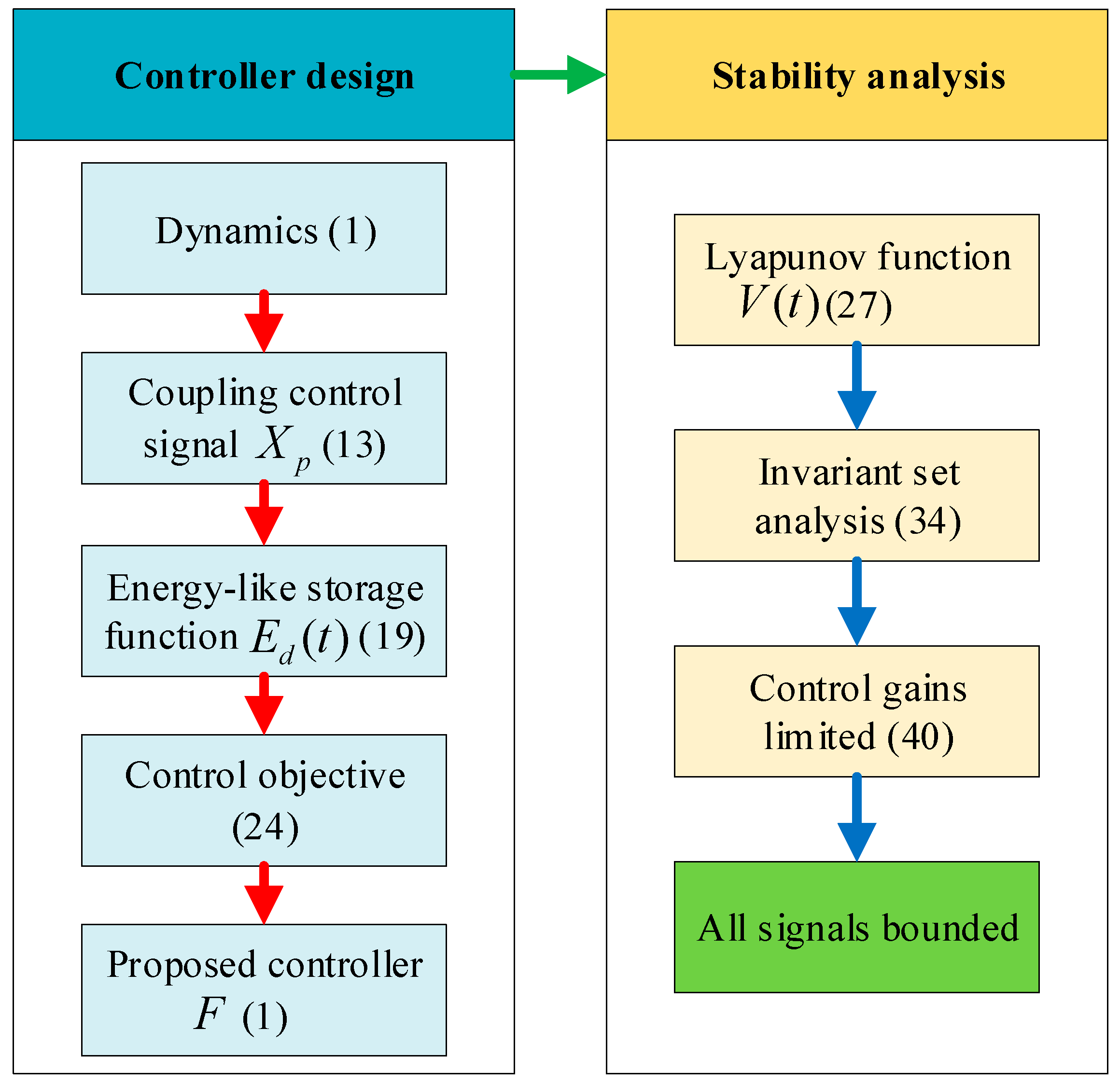
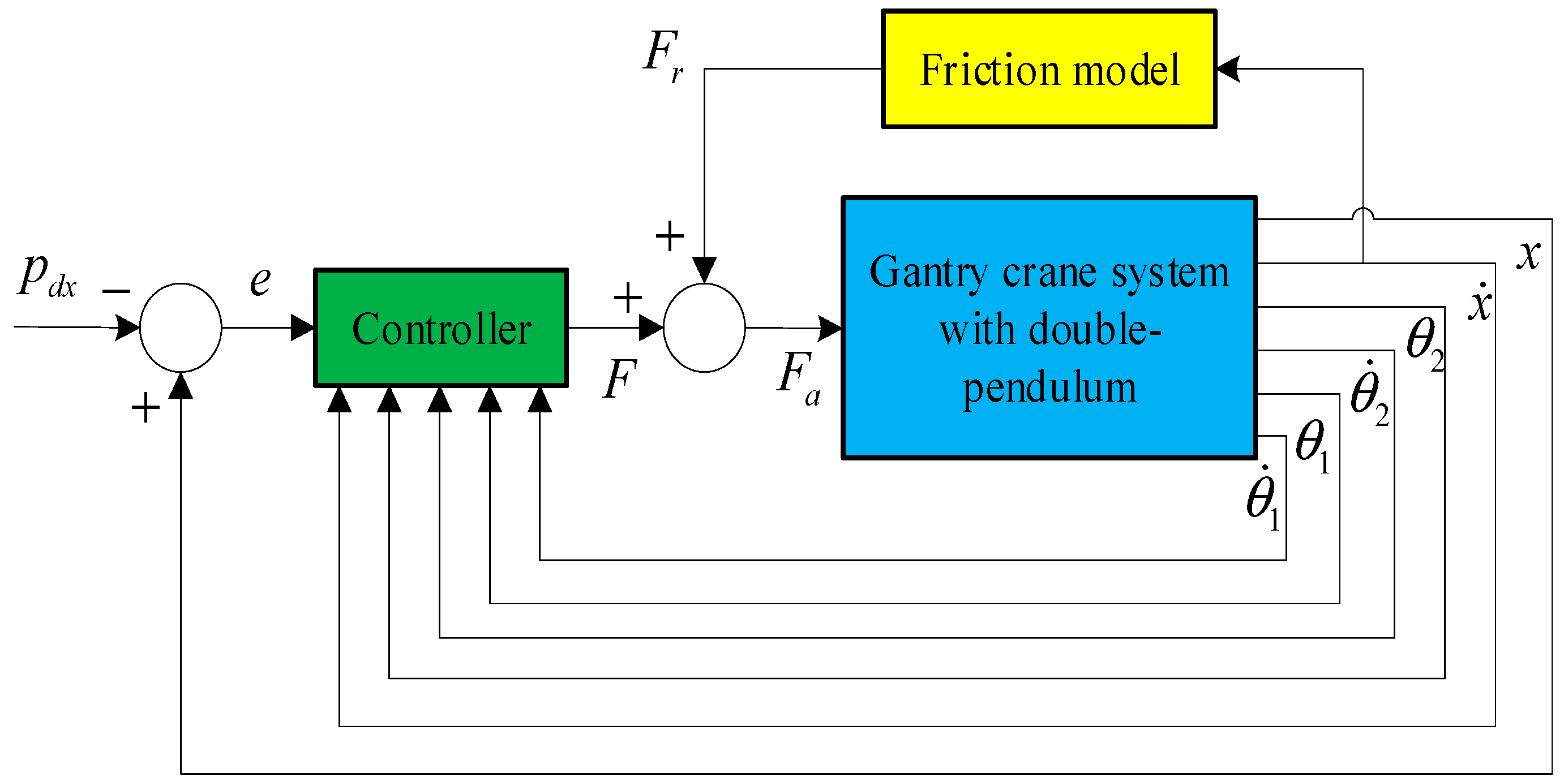
3.1. Controller Design

After some physical analysis, the entire energy E ( t ) (including potential energy and kinetic energy) of the double pendulum gantry crane can be calculated as follows [39,41]:
E ( t ) = 1 2 q ˙ T M ( q ) q ˙ + ( m 1 + m 2 ) g l 1 ( 1 cos θ 1 ) + m 2 g l 2 ( 1 cos θ 2 )
By taking the derivative of Equation (15) with respect to time, and substituting Equation (9) into the result equation can be obtained as follows.
E ˙ ( t ) = x ˙ F
It shows that the double pendulum gantry crane system is passive and dissipative under the input F ( t ) and output x ˙ ( t ) . There are no terms related to θ 1 , θ ˙ 1 , θ 2 and θ ˙ 2 in Equation (15). In order to solve this problem and improve transient control performance, we plan to construct an energy-like storage function E d ( t ) with the following expression along the time derivative of the system dynamics model (1):
E ˙ d ( t ) = X ˙ p F
where X ˙ p can be derived from the derivative of Equation (13):
X ˙ p = x ˙ + k a 1 θ ˙ 1 cos θ 1 + k a 2 θ ˙ 2 cos θ 2
Integrating Equation (17) with time to get the E d ( t ) .
E d ( t ) = 1 2 q ˙ T H ( q ) q ˙ + [ ( m 1 + m 2 ) l 1 + k a 1 ( M + m 1 + m 2 ) ] g ( 1 cos θ 1 ) + [ m 2 l 2 + k a 2 ( M + m 1 + m 2 ) ] g ( 1 cos θ 2 )
where H ( q ) is a symmetrical matrix as shown below:
H ( q ) = [ M + m 1 + m 2 ( m 1 + m 2 ) l 1 cos θ 1 m 2 l 2 cos θ 2 ( m 1 + m 2 ) l 1 cos θ 1 k a 1 [ M + ( m 1 + m 2 ) sin 2 θ 1 ] l 1 + ( m 1 + m 2 ) l 1 2 m 2 l 1 l 2 cos ( θ 1 θ 2 ) m 2 l 2 cos θ 2 m 2 l 1 l 2 cos ( θ 1 θ 2 ) k a 2 ( M + m 1 + m 2 sin 2 θ 2 ) l 2 + m 2 l 2 2 ]
In addition, we can derive the following properties of the matrix (20).
Property 1.
H ( q ) is a positive definite symmetrical matrix, which has the flowing property:
h 1 ξ 2 ξ T H ( q ) ξ h 2 ξ 2 ξ R 2
where denote the Euclidean norm of vectors, h 1 and h 2 are shown as follows:
h 1 = min { M , k a 1 M l 1 , k a 2 M l 2 } > 0
h 2 = max { M + 2 m 1 + 2 m 2 , k a 1 ( M + m 1 + m 2 ) l 1 + 2 ( m 1 + m 2 ) l 1 2 , k a 2 ( M + m 1 + m 2 ) l 2 + 2 m 2 l 2 2 }
Proof of this property can be done directly, so for the sake of brevity, it will be omitted. It can be concluded from the Property 1 that the E d ( t ) of formula (19) is also positive.
For the gantry crane control system with double-pendulum swing efforts, the basic control objectives can be expressed as:
(1). Drive the trolley to the desired location p d x .
(2). Limit and eliminate the double-pendulum swing angles θ 1 and θ 2 .
Therefore, the control objectives can be shown as the following:
lim t [ x ( t ) θ 1 ( t ) θ 2 ( t ) ] T = [ p d x 0 0 ] T
To this end, the generalized payload position error σ p ( t ) is defined as:
σ p = X p p d x = e k a 1 sin θ 1 k a 2 sin θ 2
where e ( t ) R represents the positioning error of the trolley motion.
e = x p d x
A positive definite scalar function V ( t ) is being designed based on the improved energy-like storage function E d ( t ) of (19):
V ( t ) = E d ( t ) + k p 2 σ p 2
where k p R + is a positive control gain. By taking the time derivative of V ( t ) along the system dynamics (9), (10) and (11), one can derive
V ˙ ( t ) = ( F + k p σ p ) σ ˙ p
Therefore, we designed a closed-loop feedback controller as shown below:
F = k p σ p k d σ ˙ p = k p ( e k a 1 sin θ 1 k a 2 sin θ 2 ) k d ( e ˙ k a 1 θ ˙ cos θ 1 k a 2 θ ˙ cos θ 2 )
where k d R + is a positive control gain. σ p ( t ) will be adjusted to 0. The system state will also be driven by (29) to the desired state. These will be represented in the theorems described below. In the overall double-pendulum gantry crane control system as shown in Figure 4, the actuation force F a ( t ) applied to trolley is composed of the feed forward compensation term F r ( t ) and the feedback force F ( t ) .
Remark 1.
The friction model (8) is used as the feed forward assembly to compensate for friction between the trolley and the tracks. For the sake of conciseness, we will focus on the development of the resultant force F ( t ) , because we can get the actuated force F a ( t ) directly from (7).
Remark 2.
This paper presents a simpler structure controller with σ p ( t ) and σ ˙ p ( t ) . The controller proposed in this paper takes a simpler structure with respect to σ p ( t ) and σ ˙ p ( t ) . It does not include gantry crane system parameters. This means that the controller does not rely on an accurate system parameter model.

3.2. Stability Analysis

Theorem 1.
The proposed controller (28) can drive the trolley to the desired target location p d x asymptotically and eliminate the hook swing angle θ 1 and the payload swing angle θ 2 in the following manner:
lim t [ x ( t ) x ˙ ( t ) θ 1 ( t ) θ ˙ 1 ( t ) θ 2 ( t ) θ ˙ 2 ( t ) ] T = [ p d x 0 0 0 0 0 ] T
Proof. 
The positive definite scalar function (28) is used as a Lyapunov candidate function. Substituting controller (29) into (28) and getting the following formula:
V ˙ ( t ) = k d σ ˙ p 2 0
which indicates that the closed-loop system is Lyapunov stable at the origin [45]. The following conclusions can be easily obtained:
V ( t ) L
And the state quantity of the gantry crane system is bounded. Therefore:
e ( t ) , e ˙ ( t ) , θ ˙ 1 ( t ) , θ ˙ 2 ( t ) , F x L
To prove the asymptotic convergence of the close loop system state, we let Γ be the largest invariant set in Ω , where
Ω = {   ( x , x ˙ , θ 1 , θ ˙ 1 , θ 2 , θ ˙ 2 )   |   V ˙ ( t ) = 0   }
Then, the conclusion can be obtained from (30) in Γ
σ ˙ p = x ˙ k a 1 θ ˙ 1 cos θ 1 k a 2 θ ˙ 2 cos θ 2 = 0
Therefore, the following conclusions can be drawn:
σ p = e k a 1 sin θ 1 k a 2 sin θ 2 = α
σ ¨ p = x ¨ + k a 1 ( θ ˙ 1 2 sin θ 1 θ ¨ 1 cos θ 1 ) + k a 2 ( θ ˙ 2 2 sin θ 2 θ ¨ 2 cos θ 2 ) = 0
where α R is a pending constant. Therefore, it can be derived directly from (29), (35) and (36) that
F = k p α
It can be obtained from Equation (37) that
x ¨ = k a 1 ( θ ¨ 1 cos θ 1 θ ˙ 1 2 sin θ 1 ) + k a 2 ( θ ¨ 2 cos θ 2 θ ˙ 2 2 sin θ 2 )
After some substitutions, Formula (9) can be rewritten as:
[ F ( M + m 1 + m 2 ) x ¨ ] ( m 1 + m 2 ) l 1 = θ ¨ 1 cos θ 1 θ ˙ 1 2 sin θ 1 + m 2 l 2 ( m 1 + m 2 ) l 1 ( θ ¨ 2 cos θ 2 θ ˙ 2 2 sin θ 2 )
Therefore, the relationship between k a 1 and k a 2 is set with reference to the structures of Equations (39) and (40).
k a 1 k a 2 = ( m 1 + m 2 ) l 1 m 2 l 2
Additionally, by substituting Equation (41) into the previous term (40), it can be concluded that
k a 1 [ F ( M + m 1 + m 2 ) x ¨ ] ( m 1 + m 2 ) l 1 = k a 1 ( θ ¨ 1 cos θ 1 θ ˙ 1 2 sin θ 1 ) + k a 2 ( θ ¨ 2 cos θ 2 θ ˙ 2 2 sin θ 2 )
Subsequently Equations (38) and (39) into Equation (42), it can be derived that
x ¨ = k a 1 k p k a 1 ( M + m 1 + m 2 ) + ( m 1 + m 2 ) l 1 α
Suppose that α 0 , it is concluded that
e ˙ ( t ) = x ˙ ( t ) = { + α < 0 α > 0 a s t
which contradicts the conclusion in Equation (33), so the assumption of α 0 does not hold, and in Γ
α = 0
After substituting Equation (45) into Equations (38) and (43), we can get
F = 0
x ¨ = 0
x ˙ = e ˙ = β
It is obtained in the similar way that
x ˙ = e ˙ = β = 0
Further, the swing angle θ 1 of hook and the swing angle θ 2 of payload are usually kept within 10 degrees due to the acceleration of the trolley in practice. In this case, the swing angle θ 1 of hook and the swing angle θ 2 of payload satisfy the following approximation [37,41,46,47]:
{ sin θ 1 θ 1 cos θ 1 1 sin θ 2 θ 2 cos θ 2 1
After combining Equations (9), (10), (11), (46), (47) and (50), the Equations (9)–(11) can be rewritten as follows:
( m 1 + m 2 ) l 1 θ ¨ 1 + m 2 l 2 θ ¨ 2 = 0
( m 1 + m 2 ) l 1 θ ¨ 1 + m 2 l 2 θ ¨ 2 + ( m 1 + m 2 ) g θ 1 = 0
l 1 θ ¨ 1 + l 2 θ ¨ 2 + g sin θ 2 = 0
Substituting Equation (51) into Equation (52), the following formula holds in Γ
θ 1 = 0
It can be obtained from Equation (54) that
θ ˙ 1 = 0
θ ¨ 1 = 0
It can be concluded from Equations (51), (53) and (56) that
θ 2 = 0
In the similar way, θ ˙ 2 and θ ¨ 2 can be derived as
θ ˙ 2 = 0
θ ¨ 2 = 0
Substituting Equations (45), (54) and (57) into Equation (36), we can get
e = 0
Thus, it is easily obtained from Equation (26) that
x = p d x
After the above analysis, it can be concluded that the maximum invariant set only contains the equilibrium point of lim t [ x ( t ) x ˙ ( t ) θ 1 ( t ) θ ˙ 1 ( t ) θ 2 ( t ) θ ˙ 2 ( t ) ] T = [ p d x 0 0 0 0 0 ] T . The closed-loop system states asymptotically converge to the desired ones according to LaSalle’s invariance theorem [45]. Therefore, Theorem 1 is proved. □

4. Simulation Results and Analysis

In this section, there are a series of simulations to validate the control performance of the proposed control method. The numerical simulations are implemented in Matlab/Simulink. More precisely, compared with the existing two traditional methods, the proposed method shows excellent control performance. Then, the robustness of the proposed method to the crane control system is tested, including different initial hook and payload swing disturbances, uncertain system parameters, and external disturbances. The system parameters of the double pendulum gantry crane system are shown in Table 1. The initial trolley position x ( 0 ) , the hook swing angle θ 1 ( 0 ) and the payload swing angle θ 2 ( 0 ) are determined as 0.

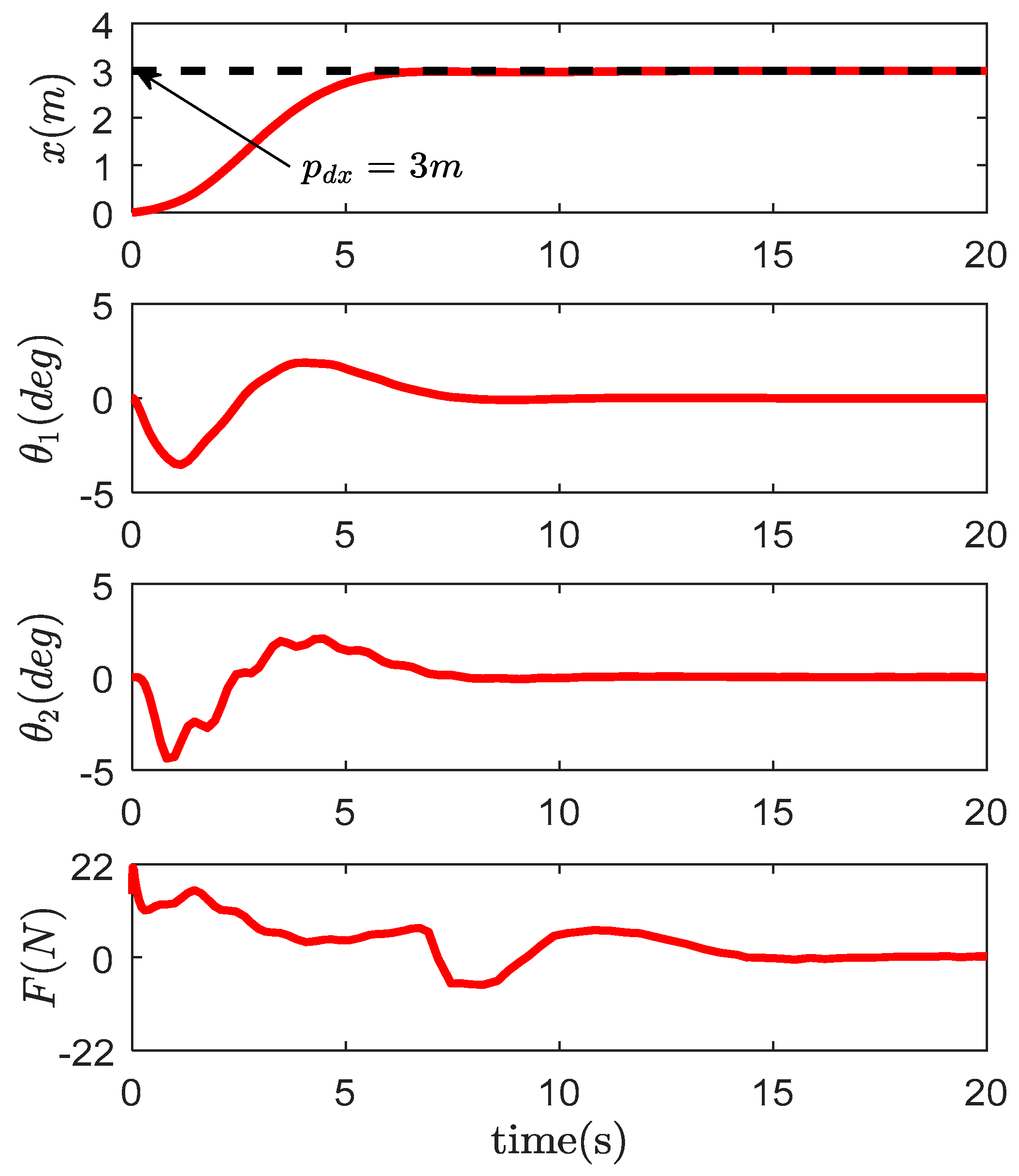
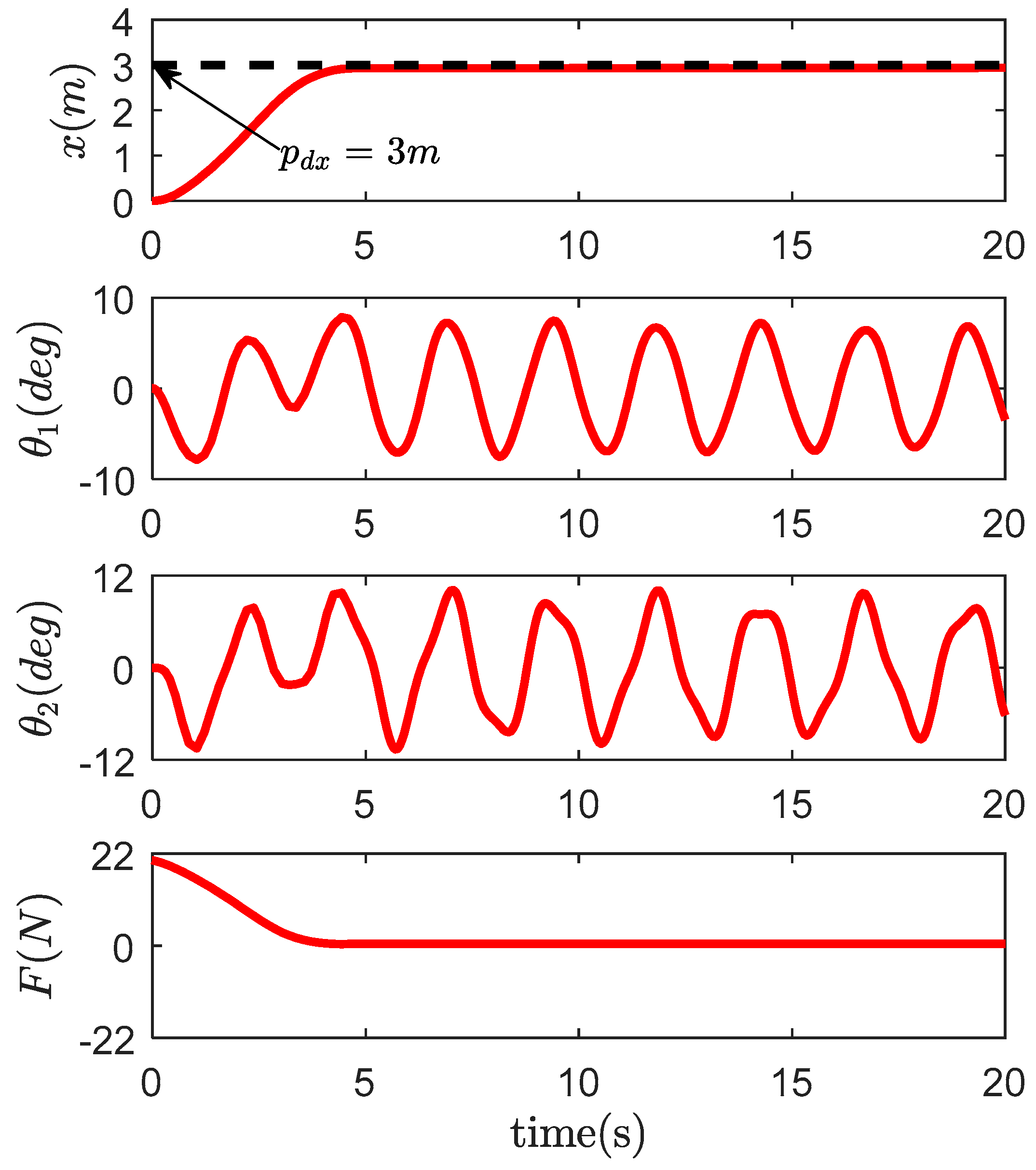
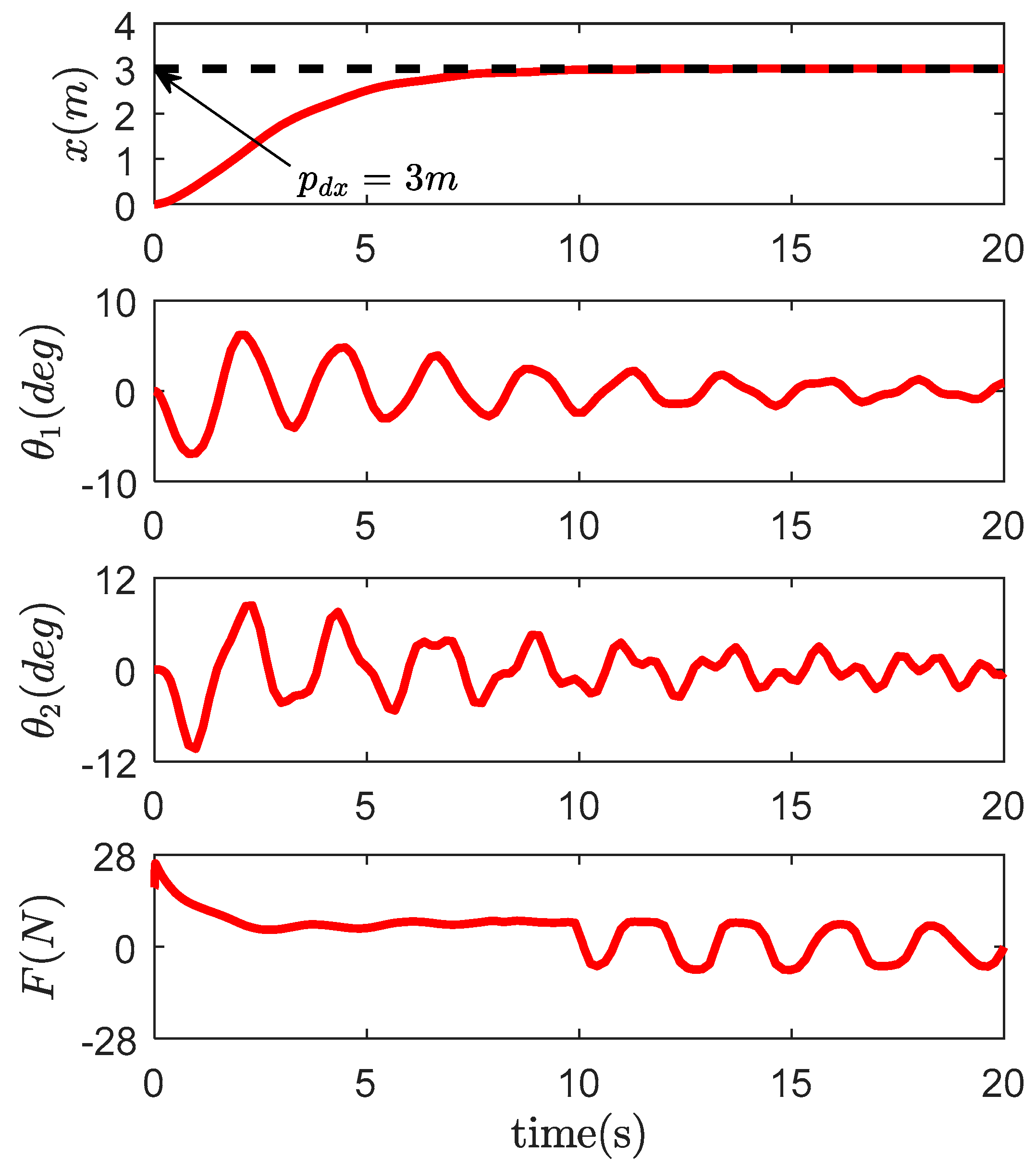
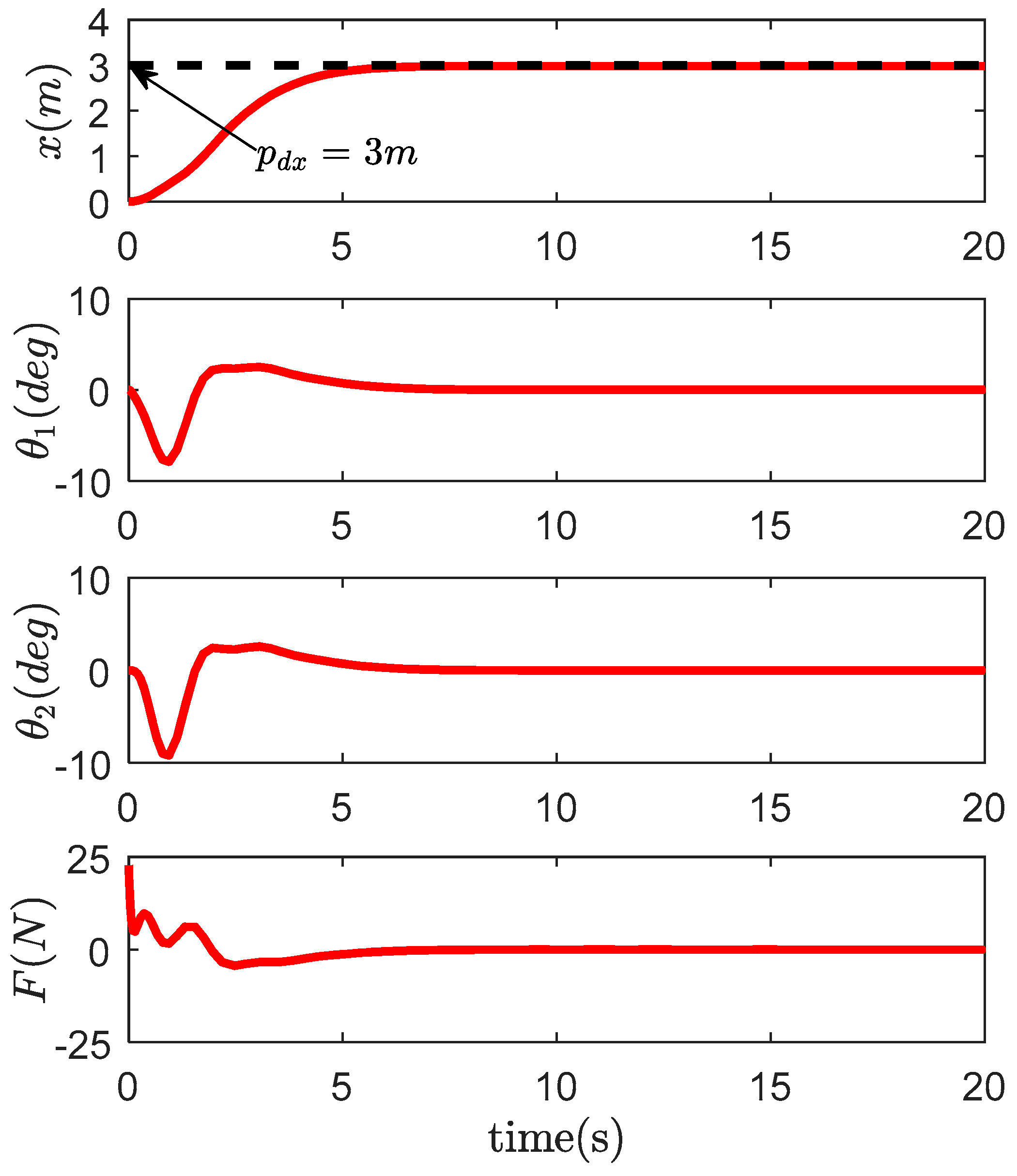
4.1. Comparative Study

We present the following three traditional control methods, including PD controller [35], passive-based controllers [36] and CSMC controllers [37]:
1. PD controller [35]:
F = F r k d x ˙ + k p ( x p d x )
where k d , k p R + are control gains.
2. Passivity-based controller [36]:
F = F r ( k e I + k D Z M 1 ( q ) Z T ) 1 × [ k p ( x p d ) + k d x ˙ + k D Z M 1 ( q ) ( C ( q , q ˙ ) q ˙ + G ( q ) ) ]
where k e , k d , k D and k p R + are control gains and I denotes available identity matrix, Z = [ 1 0 0 ] T .
3. CSMC controller [37]:
F = F r ( M + m 1 + m 2 ) ( λ x ˙ + α θ ˙ 1 + β θ ˙ 2 ) ( m 1 + m 2 ) l 1 ( cos θ 1 θ ˙ 1 θ ˙ 1 2 sin θ 1 ) m 2 l 2 θ ¨ 2 cos θ 2 m 2 l 2 θ ¨ 2 sin θ 2 K tanh ( s )
where λ , α R + and β R denote the control gains, K R + stands for the SMC gain. s is the sliding surface, and it is given as follows:
s = x ˙ + λ ( x p d ) + α θ 1 + β θ 2
We fully adjust the control gain of the proposed controller, passive controller and CSMC controller to get the best control performance. The control gain results are shown in Table 2. The simulation results and some quantitative indicators are shown in Figure 4, Figure 5, Figure 6, Figure 7 and Table 3. Table 3 includes the following five performance indicators:
1. θ 1 max / θ 2 max denote the maximum hook/payload swing amplitude during the transferring process.
2. θ 1 r e s / θ 2 r e s refer to the maximum hook/payload swing amplitude after the trolley stops.
3. p f is the trolley final position.
4. t s is defined as the time when θ 1 ( t ) and θ 2 ( t ) enter the ranges of | θ 1 ( t ) | 0.5 t t s and | θ 2 ( t ) | 0.5 t t s .
5. F max is maximum actuating during the transferring process.
It could concluded from Table 3 and Figure 5, Figure 6, Figure 7 and Figure 8 that with the similar trolley final position p f and maximum actuating F max during the transferring process, the anti-swing control performance of the designed controller in this paper is the best, as compared to other tradition controllers, such as PD controller, passivity-based controller and CSMC controller. The proposed controller effectively suppresses the hook swing angle and the payload swing angle during the transferring process. Moreover, the residual swing angle of the hook and the residual swing angle of the payload are eliminated in time after the trolley arrives at the desired positions. In particular, the proposed control method has the smallest maximal hook swing θ 1 max 3.47   deg , the smallest maximal payload swing θ 2 max 4.29   deg , the smallest residual hook swing θ 1 r e s 0.03   deg , the smallest residual payload swing θ 2 r e s 0.02   deg , the smallest setting time t s 7.46 s, and the smallest maximum actuating force F max 21.27 N. The anti-swing transient control performance of the gantry crane with double-pendulum swing effects is increased by at least 50%.

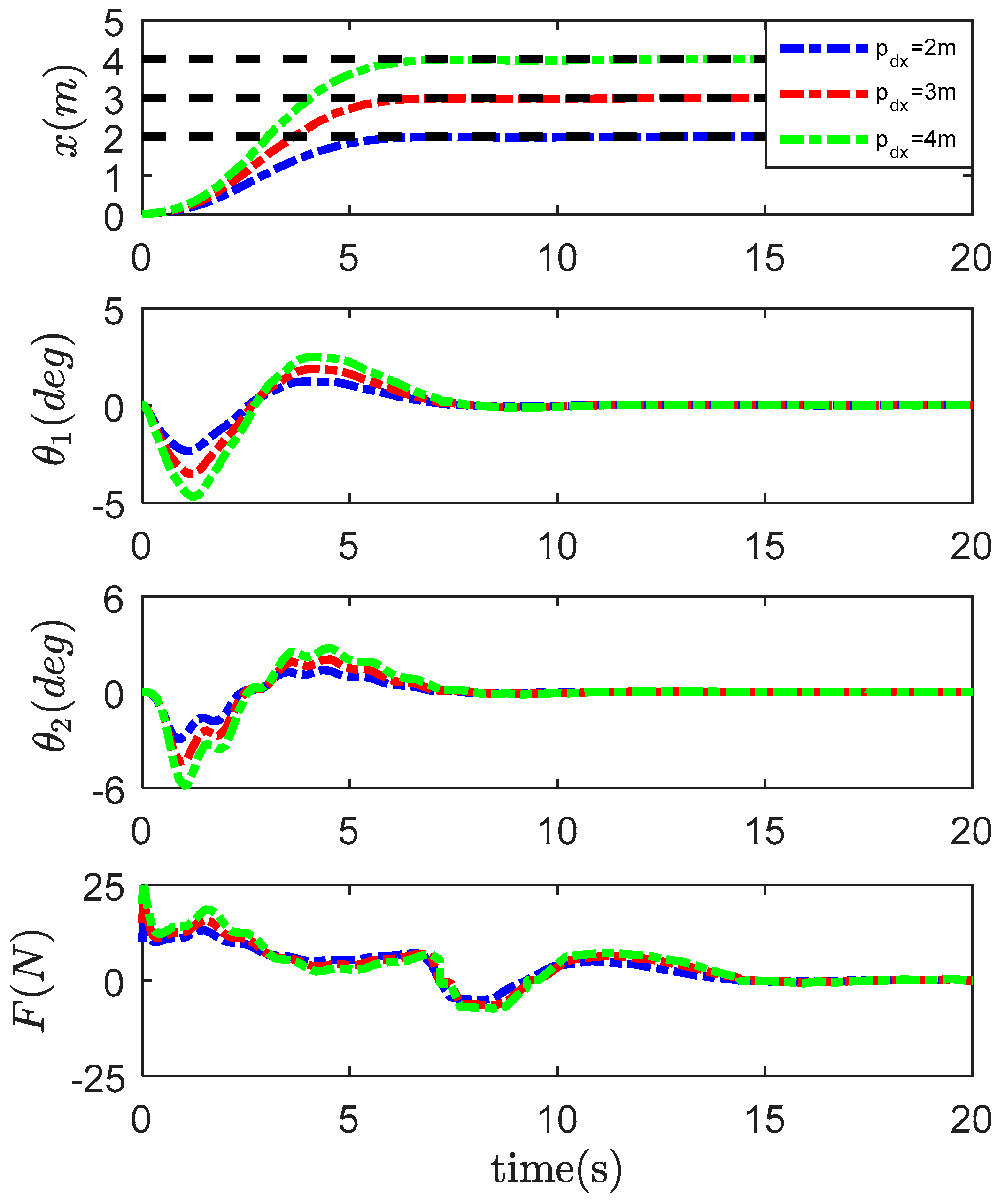
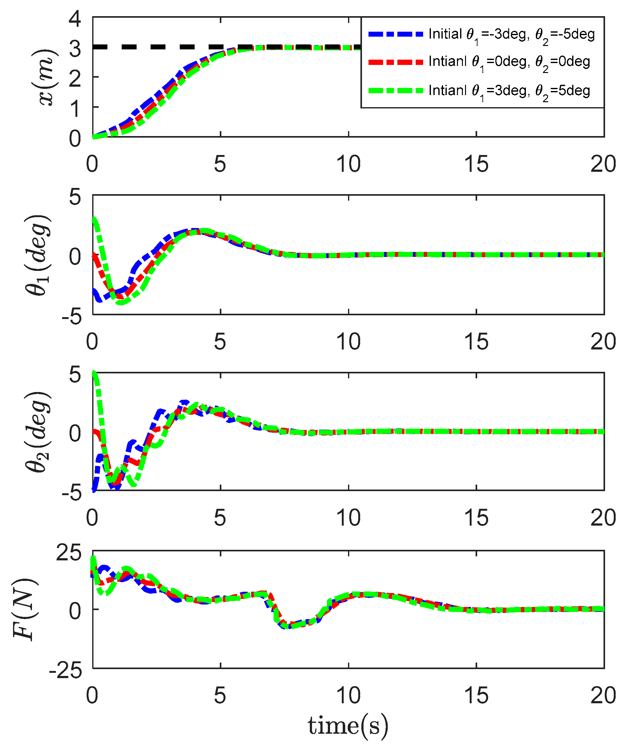
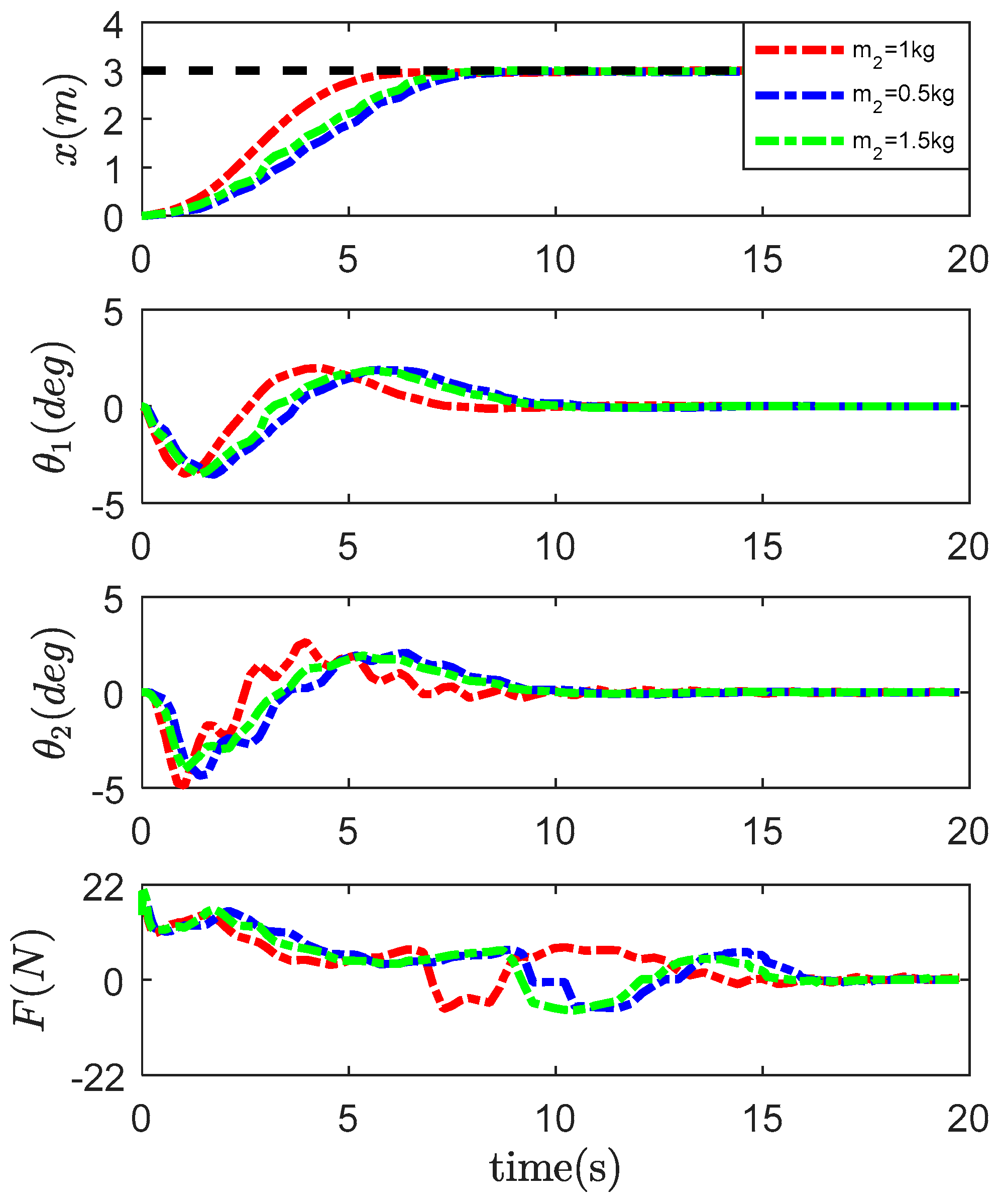
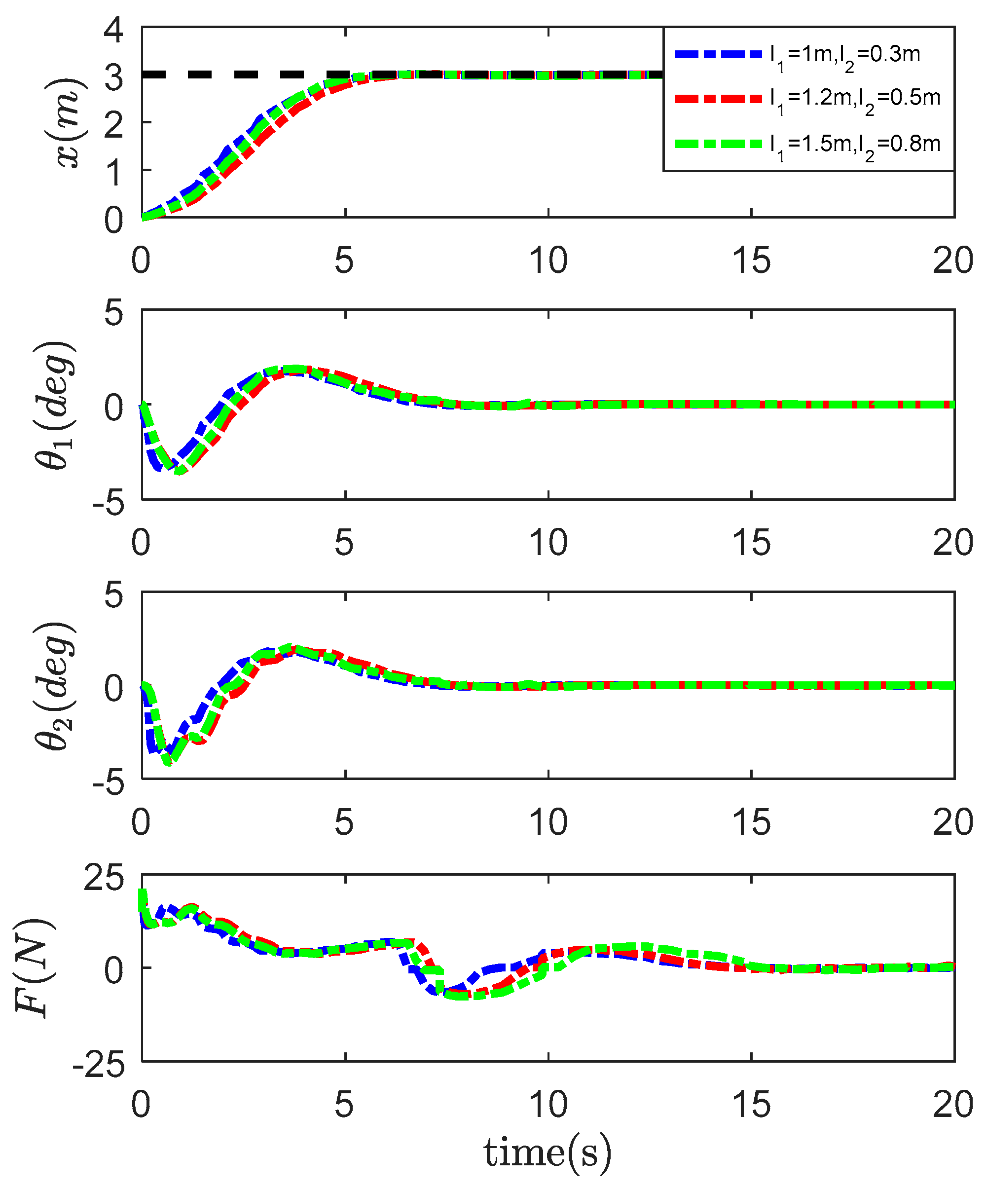
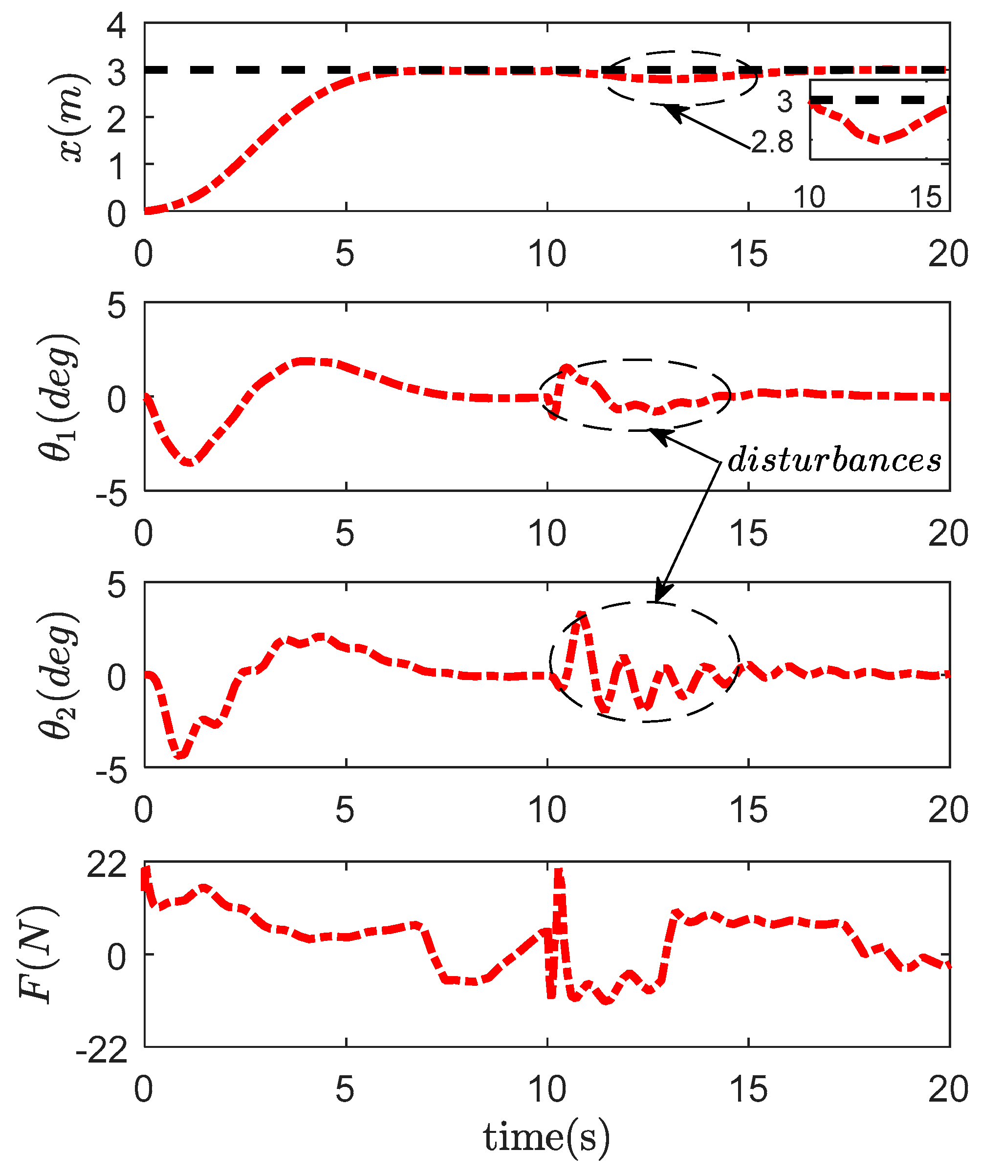
4.2. Robustness Verification

The robustness of the proposed method controller is tested with respect to different desired positions, initial payload swing, payload masses, cable lengths and external disturbances. There are five cases of numerical simulation tests in this section.
Case 1. In this case, we check the proposed controller robustness at different desired locations while keeping the control gain the same as in Table 2. Therefore, the following three transferring distances are set:
  • p d x = 2 m;
  • p d x = 3 m;
  • p d x = 4 m.
The simulation results are recorded in Figure 9. The trolley is accurately driven to the destination for different desired positions. The maximum hook swing is less than 6 degrees, and the maximum payload swing is less than 5 degrees. There is no residual swing when the trolley arrives at the desired location. It can be seen that the transferring distance has little effect on the amplitude of the double pendulum.
Case 2. Next, we add the initial swing of hook and swing of payload to disturb the gantry crane control system. The control gains are shown in Table 2. The three groups of initial swing of hook swing and swing of payload are set as:
  • Initial θ 1 = 3   deg , θ 2 = 5   deg ;
  • Initial θ 1 = 0   deg , θ 2 =   deg ;
  • Initial θ 1 = 3   deg , θ 2 = 5   deg .
The simulation results are shown in Figure 10. The hook swing and payload swing are suppressed and eliminated quickly. In addition, by comparing the three groups of simulations, we can conclude that the initial hook swing and payload swing hardly affect the control performance of the gantry crane with double pendulum.
Case 3. In this case, the control performance of the proposed controller will be tested for different payload masses. At the same time, we use the same control gains in Table 2. There are three different payload masses:
  • m 2 = 0.5 kg;
  • m 2 = 1 kg;
  • m 2 = 1.5 kg.
The simulation results are shown in Figure 11. The trolley can accurately transfer all three different mass payloads to the desired location. At the same time, hook swing and payload swing are suppressed and eliminated quickly. Therefore, the proposed control method is robust against different payload masses.
Case 4. In this case, we consider verifying the robustness of the gantry crane with double pendulum control system to different cable lengths. Three groups of different rope lengths are set as follows:
  • l 1 = 1   m , l 2 = 0.3   m ;
  • l 1 = 1.2   m , l 2 = 0.5   m ;
  • l 1 = 1.5   m , l 2 = 0.8   m .
Figure 11 shows the simulation results. From Figure 12, it can be concluded that the change in cable length does not have a significant impact on the position of the cart, the hook swing and the payload swing elimination. This indicates that the proposed controller is not sensitive to cable length uncertainty.
Case 5. There may be external disturbance such as wind resistance and collision during the transportation process of the gantry crane. In this simulation, the disturbances are added to the hook and payload swing to simulate external disturbances throughout the transportation process. We add a sine wave interference of 2 degrees between 10 s and 11 s.
Figure 13 gives the simulation results of Case 5. As can be seen from Figure 12, the trolley displacements, the hook swing angles and the payload swing angles are disturbed between 11 s and 12 s. However, the external disturbances are suppressed and eliminated within 5 s. This shows that the proposed control method is robust.

5. Conclusions

This article has presented a nonlinear coupling anti-swing control method of double pendulum gantry crane based on improved energy. First, a new energy-like storage function has been designed for the double pendulum gantry crane based on the coupling signals among the trolley motion, hook swing and payload swing. Then, a nonlinear coupling closed-loop feedback anti-swing controller has been proposed. Lyapunov techniques and LaSalle’s invariance theorem help to support the theoretical derivations. Lastly, the simulation results show the effectiveness of the proposed control method. The main contribution of the article is that the proposed controller has a better control performance than the other traditional controllers. The anti-swing suppression effect is increased by at least 50%. The designed control law is robust enough to withstand different desired locations, different initial swing angles, different payload masses and different cable lengths. The system can adjust the return to steady state within 5 s when external disturbances occur. In future work, we will focus on some experiments to test the proposed method and research the nonlinear control problems of other underactuated systems.

Author Contributions

H.S. summarized the existing research contributions in this field. G.L. analyzed the dynamic model of the double pendulum gantry crane and designed the nonlinear coupling control law. The author X.M. established the simulation model and verified the effectiveness of the proposed controller. Author J.S. author G.L. summarized the research conclusions and wrote the paper. All authors have read and approved the final manuscript for this article.

Funding

This research was supported by the National Key Research and development Program of China under the grant 2017YFC0703903 and the National Natural Science Foundation of China under the grant 51705341 &51905357.

Acknowledgments

The authors would like to thank Dr. Zhang Menghua from Shandong University for her guidance on the section of simulation results and analysis in the article. In addition, the authors are grateful to the editors and the reviewers for their suggestions to improve the quality of the paper.

Conflicts of Interest

The authors states that there is no conflict of interest.

References

  1. Ramli, L.; Mohamed, Z.; Abdullahi, A.M.; Jaafar, H.I.; Lazim, I.M. Control Strategies for Crane Systems: A Comprehensive Review. Mech. Syst. Signal Process. 2017, 95, 1–23. [Google Scholar] [CrossRef]
  2. Sun, N.; Zhang, J.; Xin, X.; Yang, T.; Fang, Y. Nonlinear output feedback control of flexible rope crane systems with state constraints. IEEE Access 2019, 7, 136193–136202. [Google Scholar] [CrossRef]
  3. Shi, H.; Li, G.; Bai, X.; Huang, J. Research on Nonlinear Control Method of Underactuated Gantry Crane Based on Machine Vision Positioning. Symmetry 2019, 11, 987. [Google Scholar] [CrossRef] [Green Version]
  4. Thakar, P.S.; Bandyopadhyay, B.; Gandhi, P. Improved output-feedback second order sliding mode control design with implementation for underactuated slosh-container system having confined track length. IET Control Theory Appl. 2017, 11, 1316–1323. [Google Scholar]
  5. Paliotta, C.; Lefeber, E.; Pettersen, K.Y.; Pinto, J.; Coast, M.; de Sousa, J.T.d.B. Trajectory Tracking and Path Following for Underactuated Marine Vehicles. IEEE Trans. Control Syst. Technol. 2019, 27, 1423–1437. [Google Scholar] [CrossRef] [Green Version]
  6. Yang, C.; Luo, J.; Pan, Y.; Liu, Z.; Su, C.-Y. Personalized Variable Gain Control With Tremor Attenuation for Robot Teleoperation. IEEE Trans. Syst. Man Cybern. Syst. 2018, 48, 1759–1770. [Google Scholar] [CrossRef]
  7. Xu, B. Composite Learning Finite-Time Control with Application to Quadrotors. IEEE Trans. Syst. Man Cybern. Syst. 2017, 48, 1–10. [Google Scholar] [CrossRef]
  8. Li, F.; Zhang, C.; Sun, B. A Minimum-Time Motion Online Planning Method for Underactuated Overhead Crane Systems. IEEE Access. 2019, 7, 54586–54594. [Google Scholar] [CrossRef]
  9. Peng, H.; Shi, B.; Wang, X.; Li, C. Interval estimation and optimization for motion trajectory of overhead crane under uncertainty. Nonlinear Dyn. 2019, 96, 1693–1715. [Google Scholar] [CrossRef]
  10. Elharfi, A. Exponential stabilization and motion planning of an overhead crane system. IMA J. Math. Control Inf. 2017, 34, 1299–1321. [Google Scholar] [CrossRef]
  11. Blajer, W.; Kołodziejczyk, K. Control of underactuated mechanical systems with servo-constraints. Nonlinear Dyn. 2007, 50, 781–791. [Google Scholar] [CrossRef]
  12. Le, A.T.; Lee, S.G. 3D cooperative control of tower cranes using robust adaptive techniques. J. Frankl. Inst. 2017, 354, 8333–8357. [Google Scholar] [CrossRef]
  13. Abdullahi, A.M.; Mohamed, Z.H.; Selamat, H.R. Adaptive output-based command shaping for sway control of a 3D overhead crane with payload hoisting and wind disturbance. Mech. Syst. Signal. Process. 2018, 98, 157–172. [Google Scholar] [CrossRef]
  14. Sun, N.; Yang, T.; Chen, H. Adaptive Anti-Swing and Positioning Control for 4-DOF Rotary Cranes Subject to Uncertain/Unknown Parameters with Hardware Experiments. IEEE Trans. Syst. Man Cybern. Syst. 2019, 49, 1309–1321. [Google Scholar] [CrossRef]
  15. Liu, R.; Li, S.; Ding, S. Nested saturation control for overhead crane systems. Trans. Inst. Meas. Control 2012, 34, 862–875. [Google Scholar] [CrossRef]
  16. Wu, X.; He, X. Nonlinear Energy-Based Regulation Control of Three-Dimensional Overhead Cranes. IEEE Trans. Autom. Sci. Eng. 2017, 14, 1297–1308. [Google Scholar] [CrossRef]
  17. Wei, H.; Shuzhi, S. Cooperative control of a nonuniform gantry crane with constrained tension. Automatica 2016, 66, 146–154. [Google Scholar]
  18. Sun, N.; Fang, Y.; Chen, H. Nonlinear Stabilizing Control for Ship-Mounted Cranes with Ship Roll and Heave Movements: Design, Analysis, and Experiments. IEEE Trans. Syst. Man Cybern. Syst. 2018, 48, 1781–1793. [Google Scholar] [CrossRef]
  19. Kolar, B.; Rams, H.; Schlacher, K. Time-Optimal flatness based control of a gantry crane. Control. Eng. Pract. 2017, 60, 18–27. [Google Scholar] [CrossRef]
  20. Golovin, I.; Palis, S. Robust control for active damping of elastic gantry crane vibrations. Mech. Syst. Signal. Process. 2019, 121, 264–278. [Google Scholar] [CrossRef]
  21. Cui, L.; Zheng, D. Visual Servoing of a Flexible Gantry Crane With a Sway Range Constraint. IEEE Control Syst. Lett. 2019, 3, 138–143. [Google Scholar] [CrossRef]
  22. Smoczek, J.; Szpytko, J. Particle Swarm Optimization-Based Multivariable Generalized Predictive Control for an Overhead Crane. IEEE/ASME Trans. Mechatron. 2016, 22, 258–268. [Google Scholar] [CrossRef]
  23. Mohamed, H.; Raafat, S.; Mostafa, S. A Hybrid Partial Feedback Linearization and Deadbeat Control Scheme for a Nonlinear Gantry Crane. J. Frankl. Inst. 2018, 355, 6286–6299. [Google Scholar]
  24. Zhou, Y.S.; Wang, Z.H. Robust motion control of a two-wheeled inverted pendulum with an input delay based on optimal integral sliding mode manifold. Nonlinear Dyn. 2016, 85, 2065–2074. [Google Scholar] [CrossRef]
  25. Vyhlidal, T.; Anderle, M.; Busek, J. Time delay algorithms for damping oscillations of suspended payload by adjusting the cable length. IEEE/ASME Trans. Mechatron. 2017, 22, 2319–2329. [Google Scholar] [CrossRef]
  26. Zavari, K.; Pipeleers, G.; Swevers, J. Gain-Scheduled Controller Design: Illustration on an Overhead Crane. IEEE Trans. Ind. Electron. 2014, 61, 3713–3718. [Google Scholar] [CrossRef]
  27. Chwa, D. Sliding Mode Control-based Robust Finite-Time Anti-Sway Tracking Control of 3-D Overhead Cranes. IEEE Trans. Ind. Electron. 2017, 64, 6775–6784. [Google Scholar] [CrossRef]
  28. Lu, B.; Fang, Y.; Sun, N. Continuous Sliding Mode Control Strategy for a Class of Nonlinear Underactuated Systems. IEEE Trans. Autom. Control 2018, 63, 3471–3478. [Google Scholar] [CrossRef]
  29. Frikha, S.; Djemel, M.; Derbel, N. A New Adaptive Neuro-Sliding Mode Control for Gantry Crane. Int. J. Control Autom. Syst. 2018, 16, 559–565. [Google Scholar] [CrossRef]
  30. Bock, M.; Kugi, A. Real-Time Nonlinear Model Predictive Path-Following Control of a Laboratory Tower Crane. IEEE Trans. Control Syst. Technol. 2014, 22, 1461–1473. [Google Scholar] [CrossRef]
  31. Küchler, S.; Mahl, T.; Jörg, N. Active Control for an Offshore Crane Using Prediction of the Vessel’s Motion. IEEE/ASME Trans. Mechatron. 2011, 16, 297–309. [Google Scholar] [CrossRef]
  32. Wu, Z.; Xia, X.; Zhu, B. Model predictive control for improving operational efficiency of overhead cranes. Nonlinear Dyn. 2015, 79, 2639–2657. [Google Scholar] [CrossRef]
  33. Nakagawa, K.; Watanabe, T.; Seto, K. H infinity robust motion and vibration control of three dimensional two link flexible robot arm taking account of variation of orientation. Trans. Jpn. Soc. Mech. Eng. Ser. C 2012, 78, 1085–1096. [Google Scholar] [CrossRef]
  34. Mystkowski, A.; Pawluszewicz, E. Remarks on some robust nonlinear observer and state-feedback zero-bias control of AMB. In Proceedings of the IEEE 2015 16th International Carpathian Control. Conference (ICCC), Szilvasvarad, Hungary, 2015; pp. 328–333. [Google Scholar]
  35. Fang, Y. Nonlinear Coupling Control Laws for an Underactuated Overhead Crane System. IEEE/ASME Trans. Mechatoronics 2003, 8, 418–423. [Google Scholar] [CrossRef] [Green Version]
  36. Guo, W.; Liu, D.; Yi, J.; Zhao, D. Passivity-based control for double-pendulum-type overhead cranes. In Proceedings of the IEEE Region 10th Conference Analog and Digital Techniques in Electrical Engineering TENCON, Chiang Mai, Thailand, 24 November 2004; pp. 546–549. [Google Scholar]
  37. Tuan, L.A.; Lee, S.G. Sliding mode controls of double-pendulum crane systems. J. Mech. Sci. Technol. 2013, 27, 1863–1873. [Google Scholar] [CrossRef]
  38. Qian, D.; Tong, S.; Yang, B. Design of simultaneous input-shaping-based SIRMs fuzzy control for double-pendulum-type overhead cranes. Bull. Pol. Acad. Sci. Tech. Sci. 2015, 63, 887–896. [Google Scholar] [CrossRef]
  39. Sun, N.; Yang, T.; Fang, Y. Transportation Control of Double-Pendulum Cranes with a Nonlinear Quasi-PID Scheme: Design and Experiments. IEEE Trans. Syst. Man Cybern. Syst. 2019, 49, 1408–1418. [Google Scholar] [CrossRef]
  40. Sun, N.; Wu, Y.; Fang, Y. Nonlinear Antiswing Control for Crane Systems with Double-Pendulum Swing Effects and Uncertain Parameters: Design and Experiments. IEEE Trans. Autom. Sci. Eng. 2018, 15, 1413–1422. [Google Scholar] [CrossRef]
  41. Zhang, M.; Ma, X.; Rong, X. A novel energy-coupling-based control method for double-pendulum overhead cranes with initial control force constraint. Adv. Mech. Eng. 2018, 10, 1–13. [Google Scholar] [CrossRef] [Green Version]
  42. Zhang, M.; Zhang, Y.; Cheng, X. An Enhanced Coupling PD with Sliding Mode Control Method for Underactuated Double-pendulum Overhead Crane Systems. Int. J. Control Autom. Syst. 2019, 17, 1579–1588. [Google Scholar] [CrossRef]
  43. Zhang, M.; Ma, X.; Chai, H. A novel online motion planning method for double-pendulum overhead cranes. Nonlinear Dyn. 2016, 85, 1079–1090. [Google Scholar] [CrossRef]
  44. Boscariol, P.; Richiedei, D. Robust point-to-point trajectory planning for nonlinear underactuated systems: Theory and experimental assessment. Robot. Comput. Integr. Manuf. 2018, 50, 256–265. [Google Scholar] [CrossRef]
  45. Khalil, H. Nonlinear Systems, 3rd ed.; Englewood Cliffs NJ: Bergen, NJ, USA, 2002. [Google Scholar]
  46. Maghsoudi, M.J.; Mohamed, Z.; Sudin, S. An improved input shaping design for an efficient sway control of a nonlinear 3D overhead crane with friction. Mech. Syst. Signal. Process. 2017, 92, 364–378. [Google Scholar] [CrossRef]
  47. Soon, C.; Ghazali, R.; Hazriq, I. Robustness Analysis of an Optimized Controller via Particle Swarm Algorithm. Adv. Sci. Lett. 2017, 23, 11187–11191. [Google Scholar] [CrossRef]
Figure 1. Phenomenon of the gantry crane with double-pendulum.
Symmetry 11 01511 g001
Figure 2. Model of an underactuated gantry crane with double-pendulum.
Symmetry 11 01511 g002
Figure 3. Block diagram for the controller design and analysis.
Symmetry 11 01511 g003
Figure 4. Block diagram for the overall control system.
Symmetry 11 01511 g004
Figure 5. Simulation results for the proposed method controller.
Symmetry 11 01511 g005
Figure 6. Simulation results for the proportional derivative (PD) controller.
Symmetry 11 01511 g006
Figure 7. Simulation results for the passivity-based controller.
Symmetry 11 01511 g007
Figure 8. Simulation results for the conventional sliding mode control (CSMC) controller.
Symmetry 11 01511 g008
Figure 9. Simulation results for the proposed method controller with respect to Case 1.
Symmetry 11 01511 g009
Figure 10. Simulation results for the proposed method controller with respect to Case 2.
Symmetry 11 01511 g010
Figure 11. Simulation results for the proposed method controller with respect to Case 3.
Symmetry 11 01511 g011
Figure 12. Simulation results for the proposed method controller with respect to Case 4.
Symmetry 11 01511 g012
Figure 13. Simulation results for the proposed method controller with respect to Case 5.
Symmetry 11 01511 g013
Table 1. Gantry crane system parameters.
NameSymbolNumerical ValueUnit
Trolley mass M 12kg
Hook mass m 1 1.5kg
Payload mass m 2 1kg
Gravity acceleration g 9.8m/s2
Cable length 1 l 1 1.2m
Cable length 2 l 2 0.5m
Desired trolley location p d x 3m
Static friction-related coefficient 1 f r 0 8NA
Static friction-related coefficient 2 ξ 0.01NA
Viscous friction-related parameter k r −1.2NA
Table 2. Control gains for different controllers.
Controllers k p k d k a 1 k a 2 k e k D λ α β K
Proposed method51561NANANANANANANA
PD6.82NANANANANANANANA
Passivity-based6.520NANA11NANANANA
CSMCNANANANANANA0.517−1130
Table 3. Control performances comparison for different controllers.
Controllers θ 1 max
(deg)
θ 2 max
(deg)
θ 1 r e s
(deg)
θ 2 r e s
(deg)
p f
(m)
t s
(s)
F max
(N)
Proposed method3.474.290.030.023.0057.4621.27
PD7.8510.627.209.692.936> 2021.40
Passivity-based6.949.951.692.372.989> 2025.40
CSMC7.899.180.040.042.9867.7522.82

