Risk Control Standard and Construction Control Technology of Shield Tunnel Passing through Irregular-Plate Bridge

Abstract
:1. Introduction
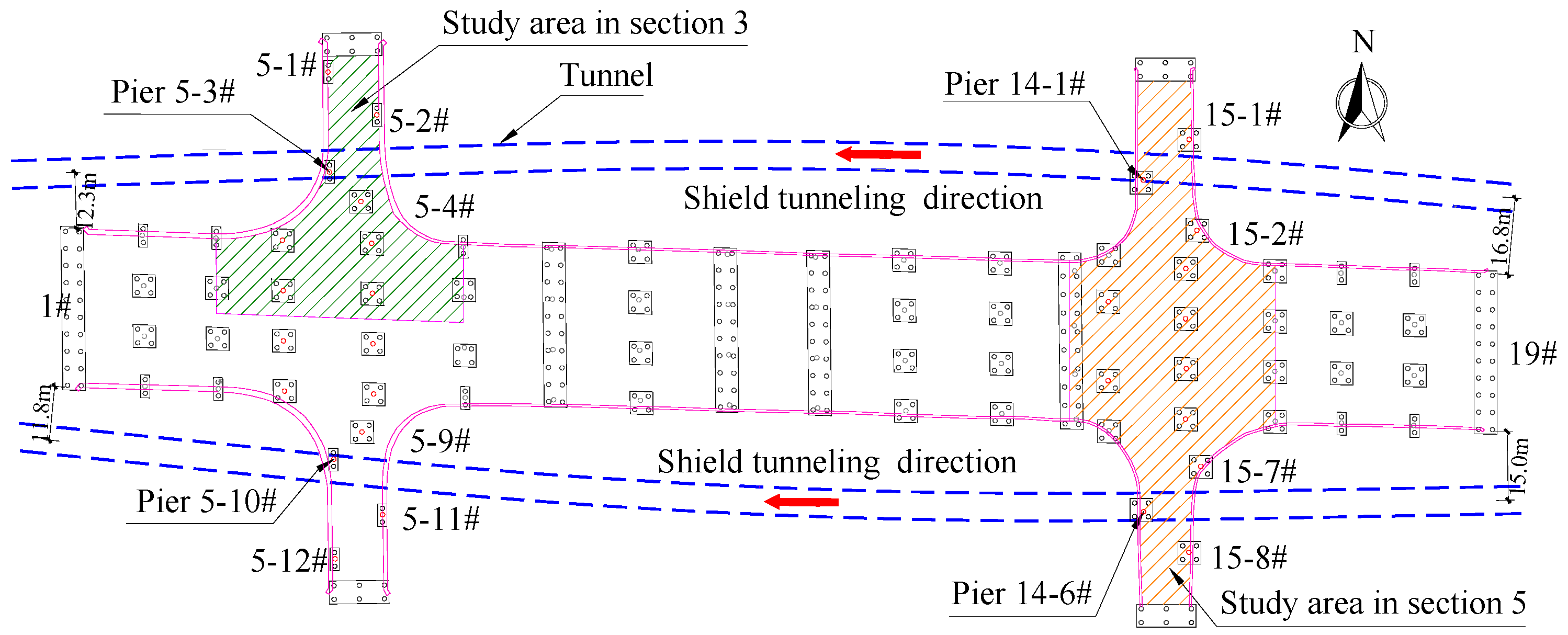
2. Engineering Conditions
- (1)
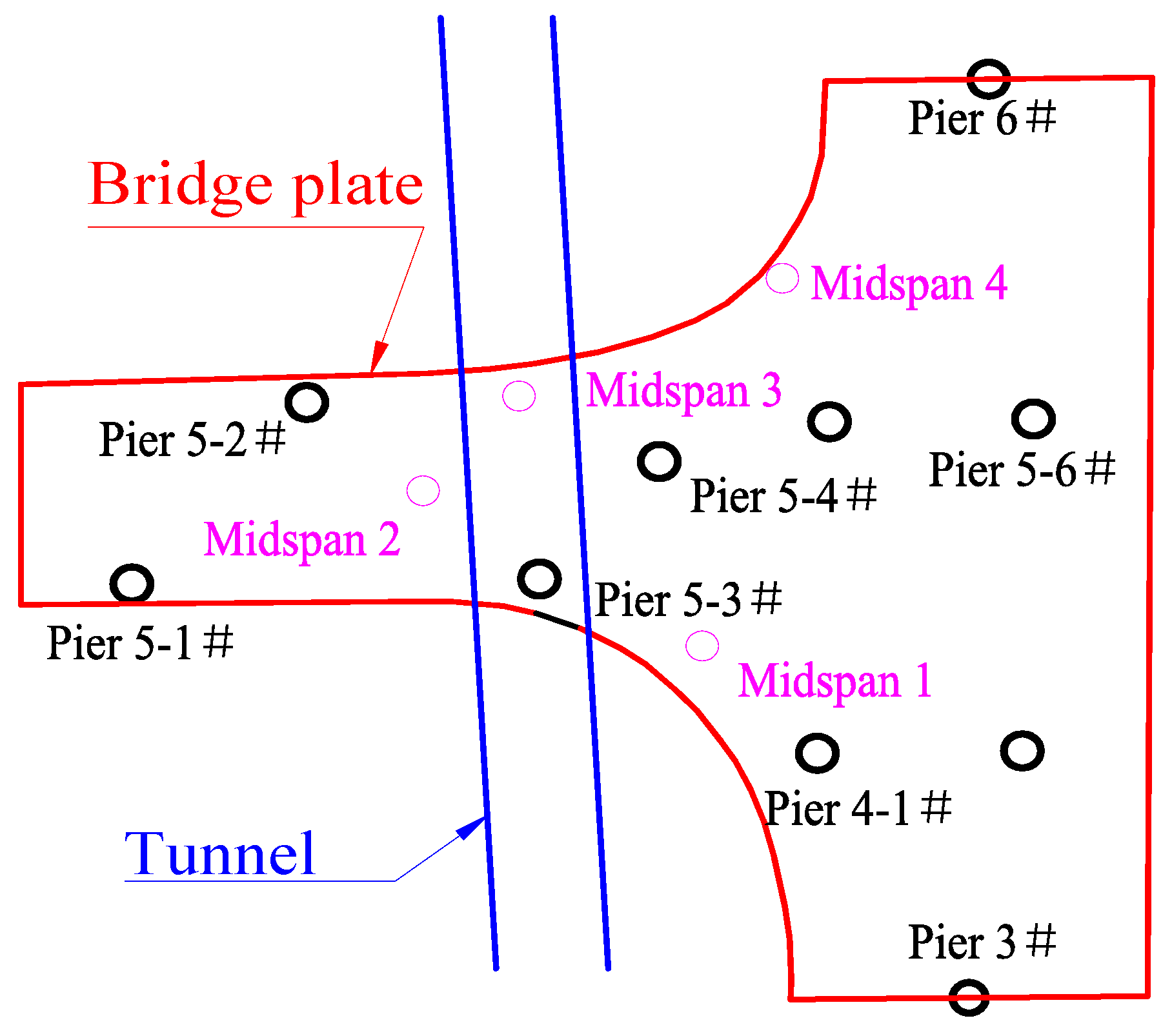
- The irregular-plate is supported by multiple pier points; the bearing capacity of each pier is different, and the middle pier is larger.
- (2)
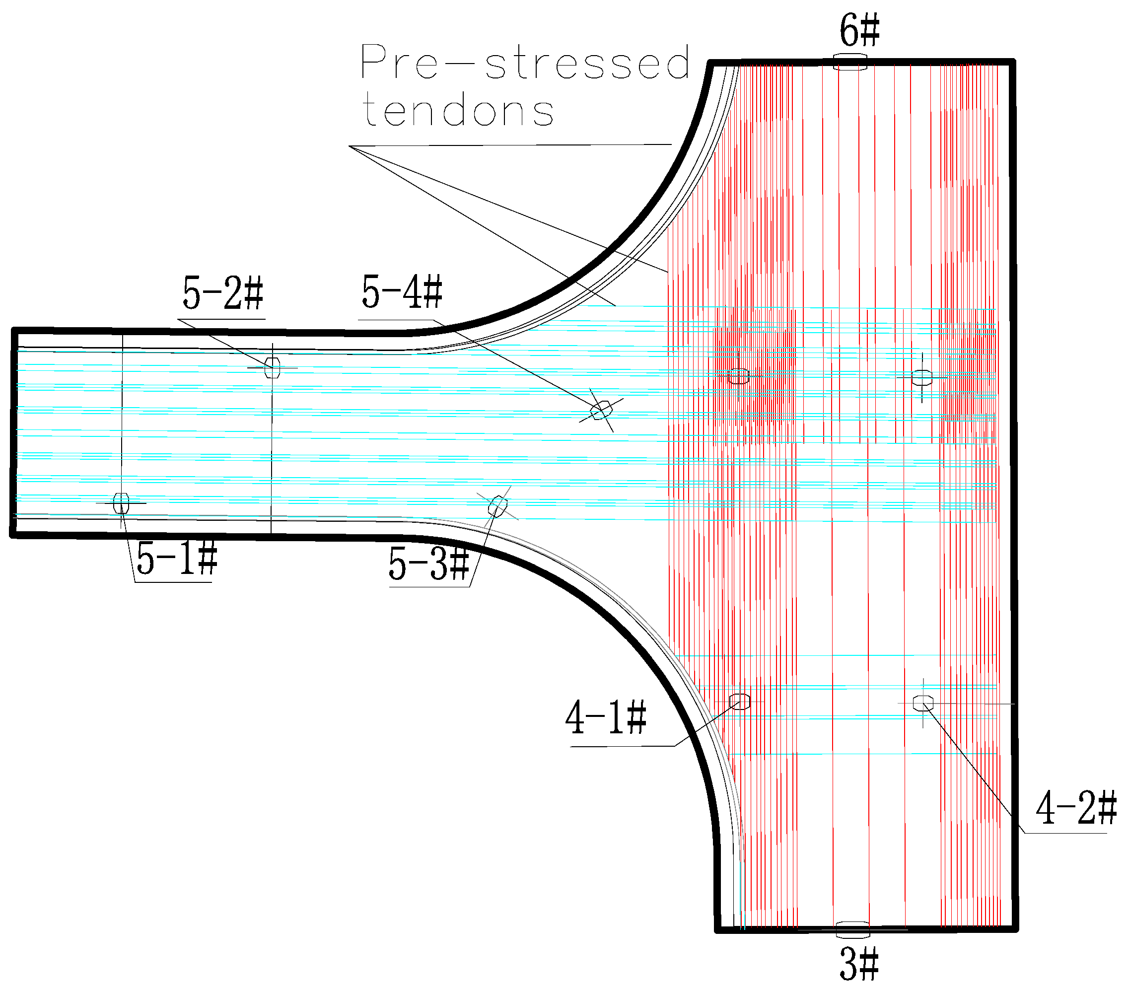
- The irregular-plate is equipped with shear reinforcement, stirrups and other measures for resisting the counterforce of piers at the fulcrum position, thus dispersing the concentrated force and avoiding the impact on the irregular plate.
- (3)
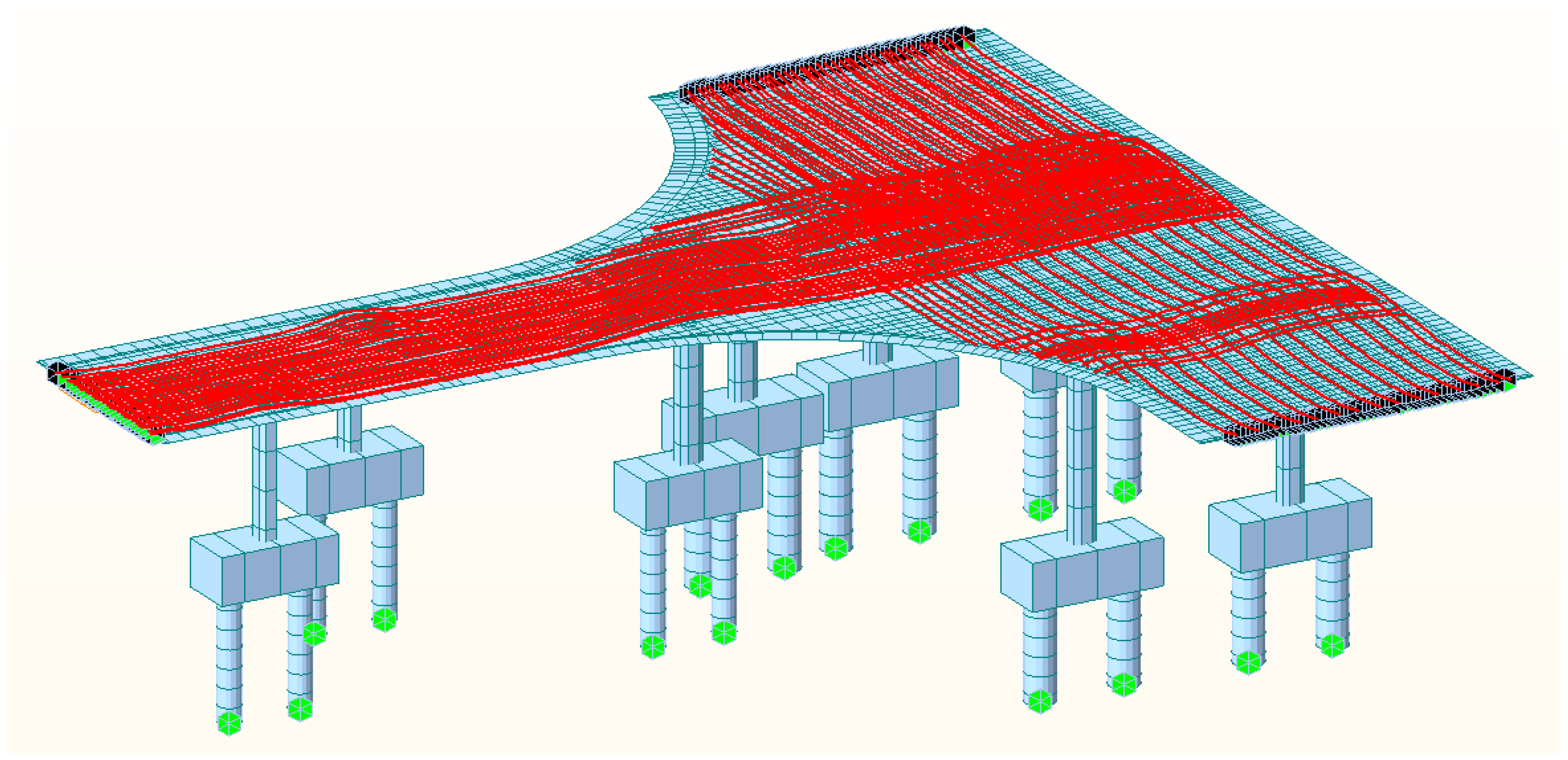
- Because of the irregular geometric shape, the combined action of self-weight and traffic load causes the irregular-plate to generate larger torque, and this causes stress on the irregular-plate to present a spatial state.
3. Analysis of Deformation Standard of the IPB
- (1)
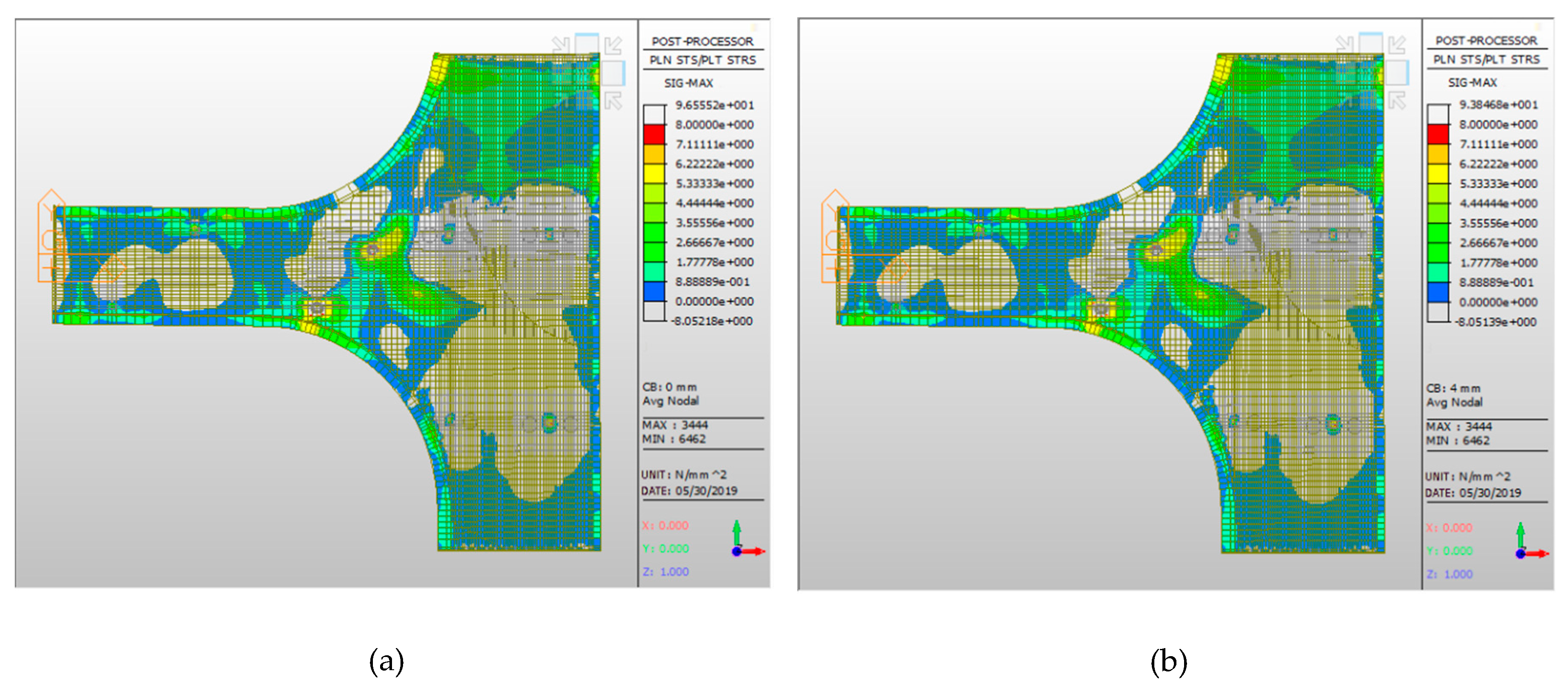
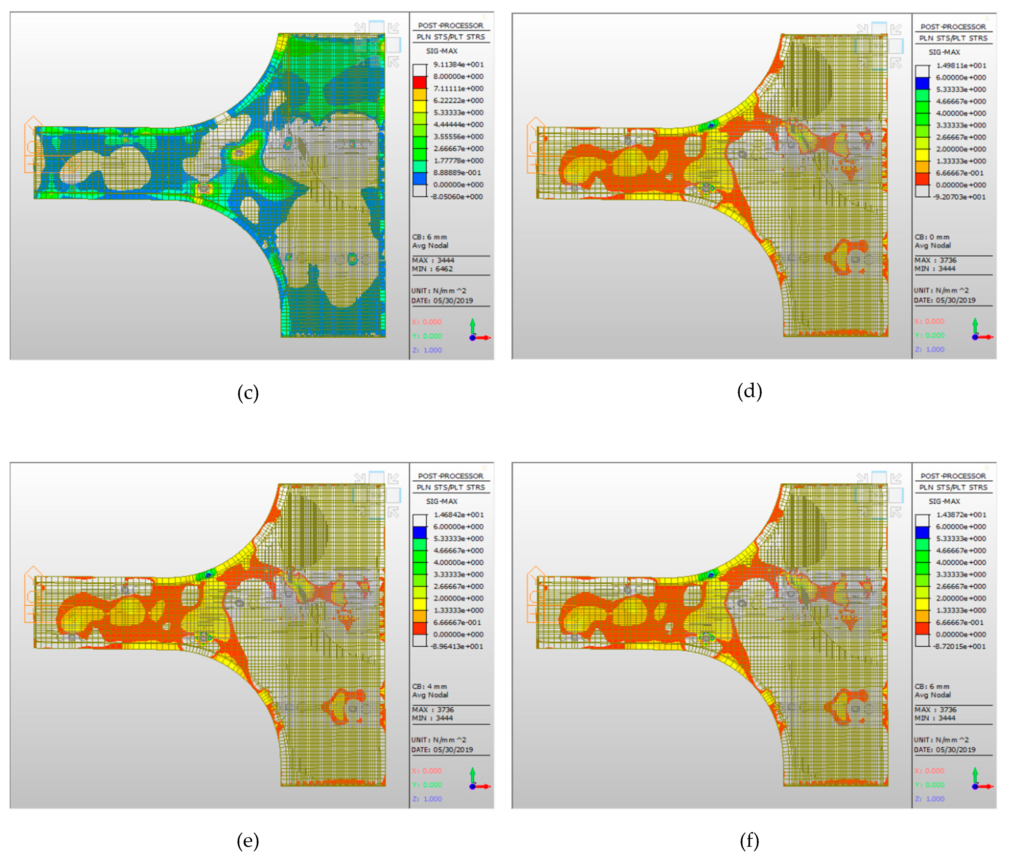
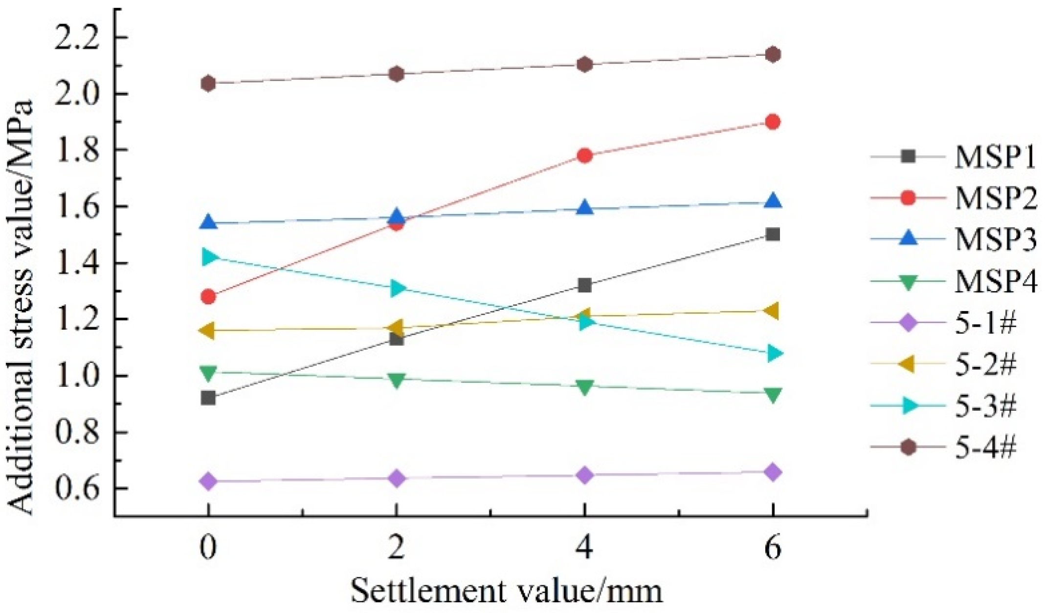
- The tensile area (Yellow and Orange areas in Figure 7) at the bottom of the plate is concentrated at the midspan of piers 5-1# to 5-4#. During the settlement process, the tensile stress at the bottom of the plate at the midspan is close to the tensile strength of concrete, and cracks occur easily.
- (2)
- With a gradual increase in the settlement, the tensile stress of at the top of the plate on the pier 5-3# gradually decreases, but the tensile stress at the top of the plate on adjacent piers increases.
- (3)
- The tensile stress of the plate at the midspan positions 1 (MSP1) and 2 (MSP2) of pier 5-3# are sensitive to the settlement of the pier, and the additional stress change rates of the irregular-plate at the midspan position 2 is 0.12 MPa/mm. When the foundation settlement reaches 3 mm, the total stress at the midspan position 2 is 1.66 MPa, and this value exceeds the C40 concrete tensile design value (1.65 MPa) and causes the bottom surface of the plate to crack.
- (4)
- While it can be seen from Figure 8 that the maximum tensile stress in the irregular-plate is located at the top of the plate on the pier 5-4#, because the joint structure of the plate on the pier was reinforced at the beginning of the design, this is not the most unfavorable control point of the irregular-plate.
4. Risk Analysis of Shield Tunnel Passing the IPB
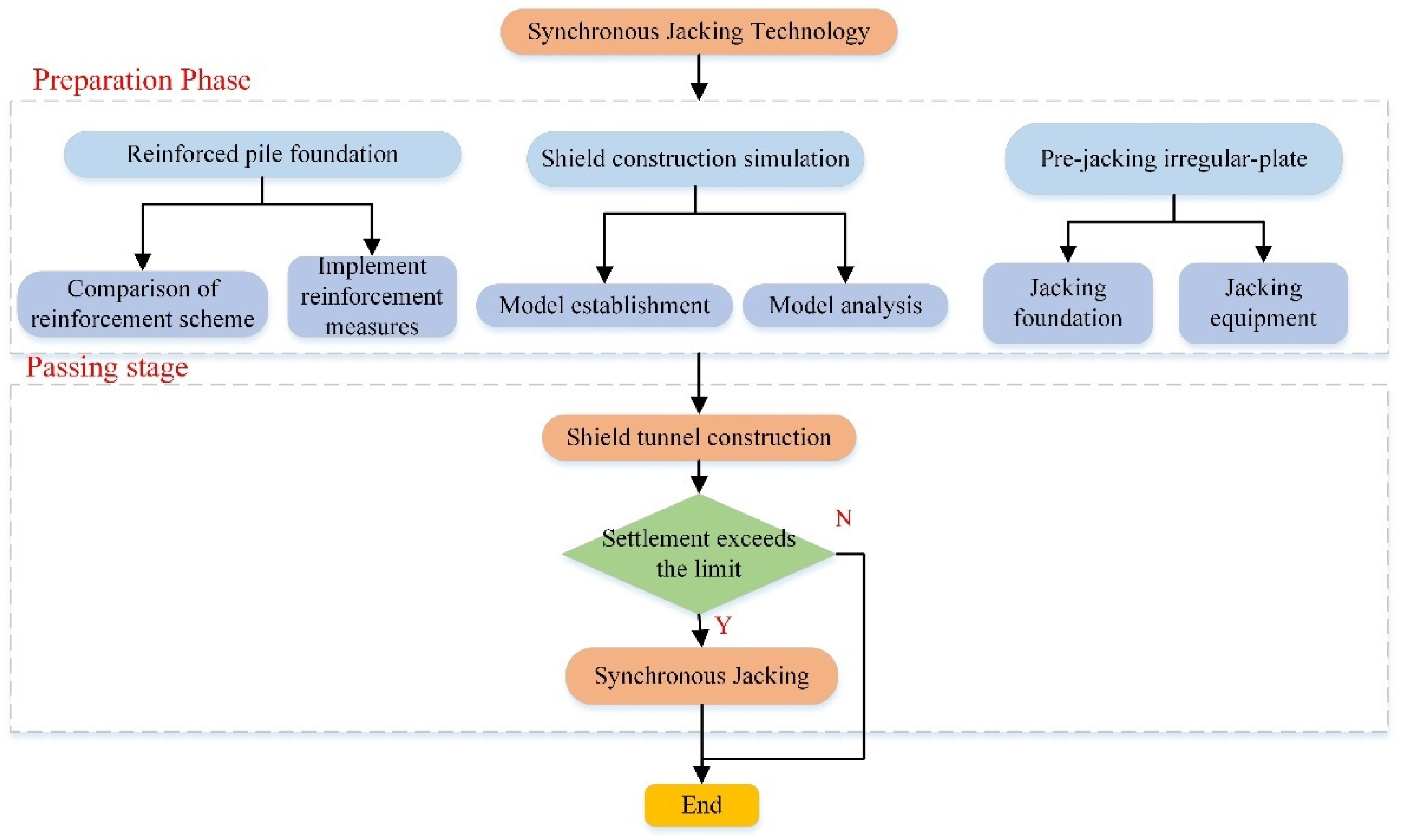
4.1. Technology Scheme for Shield Tunnels Passing the IPB
- (1)
- Effective measures should be taken in construction of the subway shield tunnel to ensure that the bridge does not suffer sudden changes in settlement, and the settlement rate of the pier should be less than 1 mm/d.
- (2)
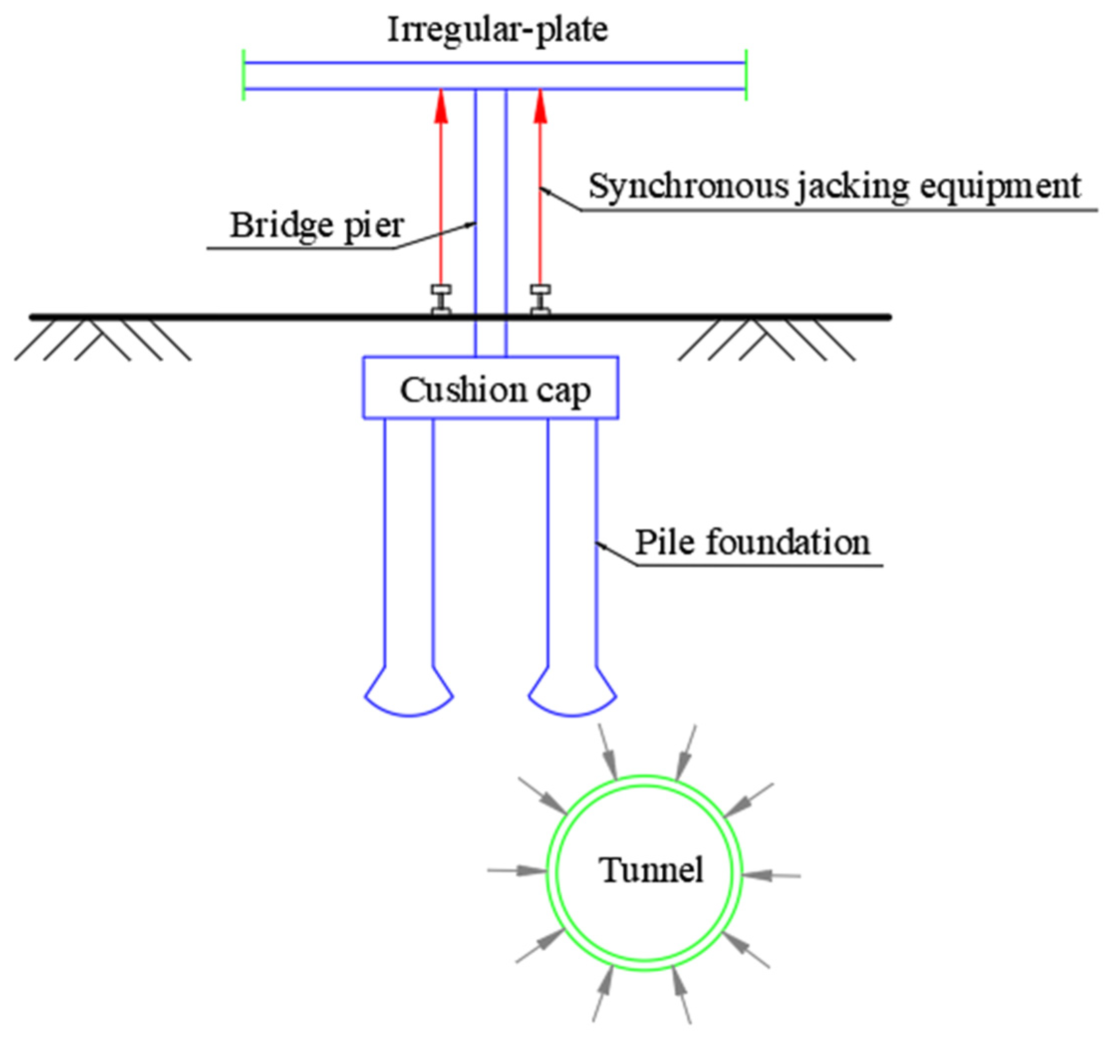
- Jacking uses a combination of mechanical jacks and hydraulic jacks. The hydraulic jacks are used to control the jack-up process. After jacking to its place, the mechanical jacks are used for locking. The self-locking performance of the mechanical jacks is stable, and its long-term settlement is not more than 0.5 mm.
4.2. Construction Risk Analysis of Shield Tunnels Passing the IPB
5. Analysis of Influences of Shield Tunnel Construction on Pile Foundation
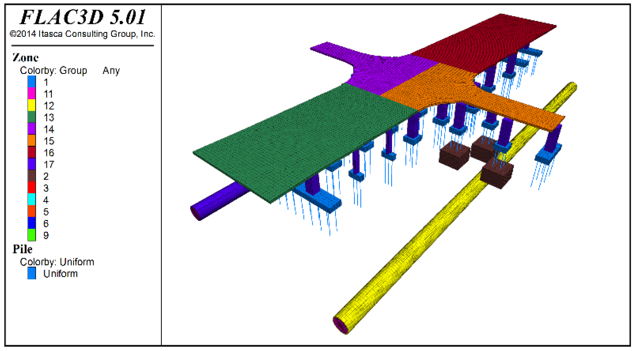
5.1. Calculation Model and Parameters
- (1)
- Setting soil parameters and boundary conditions: Only the self-weight effect is considered, the initial stress field is calculated and the displacement field and velocity field are cleared.
- (2)
- Setting the material parameters of the bridge structure: The structural weight is taken into account. The equivalent load of the upper structure on the cap is applied. The stress field before the construction of a new tunnel is obtained, and the displacement field and velocity field are cleared.
- (3)
- Shield excavation: First, the first ring soil and shield segment are passivated, and a support force at the excavation surface is applied. Second, the contact surface between the shield shell and the soil is established, the stiffness parameter is assigned to simulate the friction between the shield shell and the soil, and the shield shell unit is activated. Third, a thrust with the jack at the position of the segment is applied. Fourth, the grouting layer of the shield tail is changed to the equivalent layer parameter before hardening, and grouting pressure is applied. Next, an equivalent layer is assigned to the hardened parameters, and the above steps are repeated until construction is completed.
5.2. Analysis of Influences of Shield Tunnel Construction on Pile Foundation
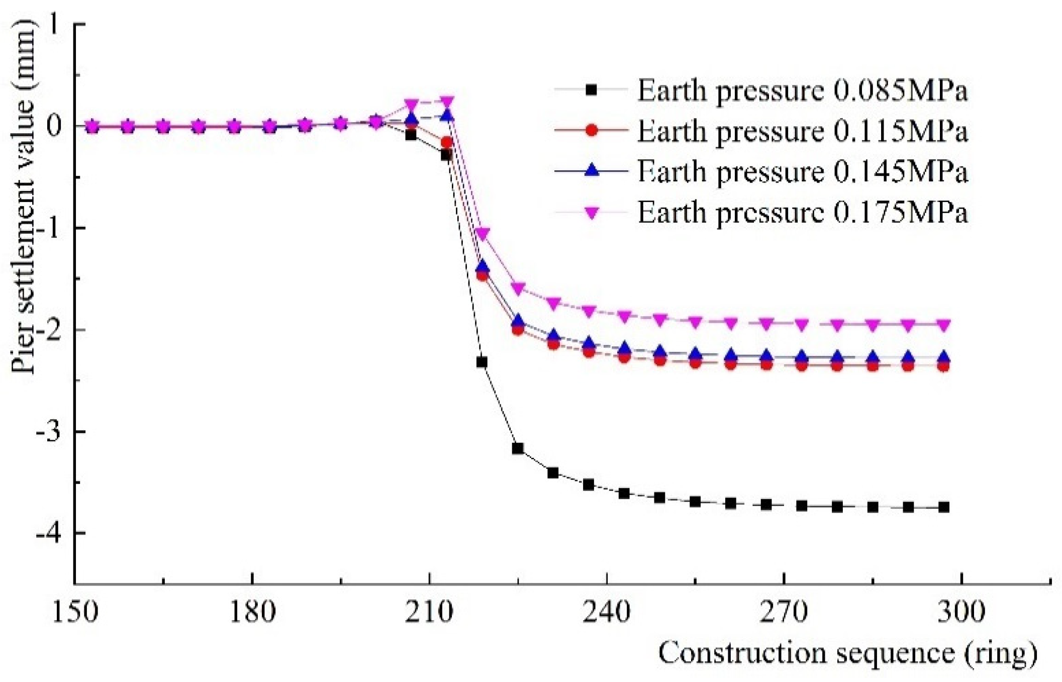
5.2.1. Analysis of Influences of Different Shield Supporting Forces on Bridge Pile Settlements
5.2.2. Overall Analysis of Settlement of IPB Piers during Shield Tunnel Construction
6. Analysis of Construction Control Results of Shield Tunnels
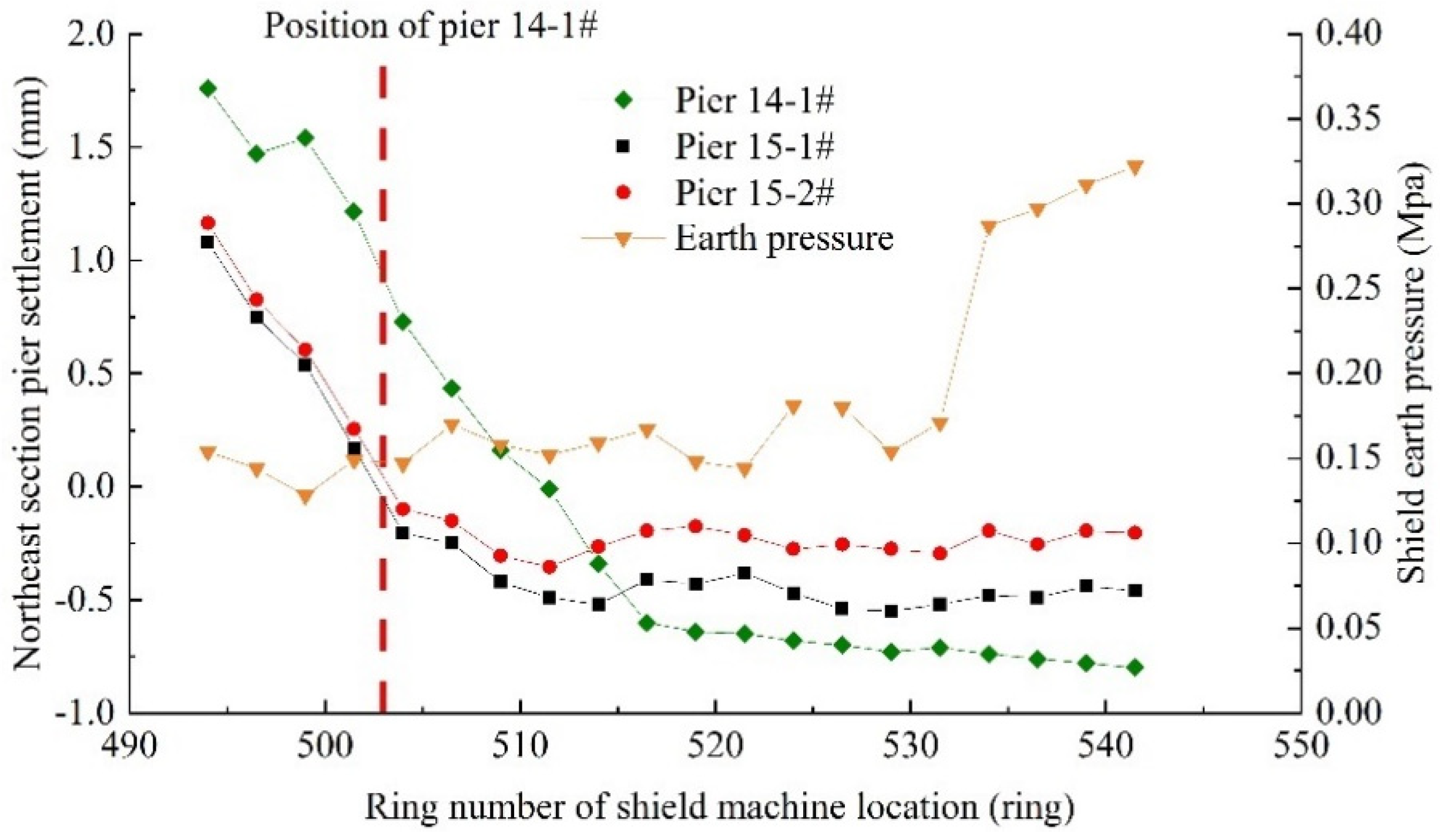
6.1. Analysis of Control Effect of Excavation Face Pressure on Pile Foundation Settlement of Shield Tunnel
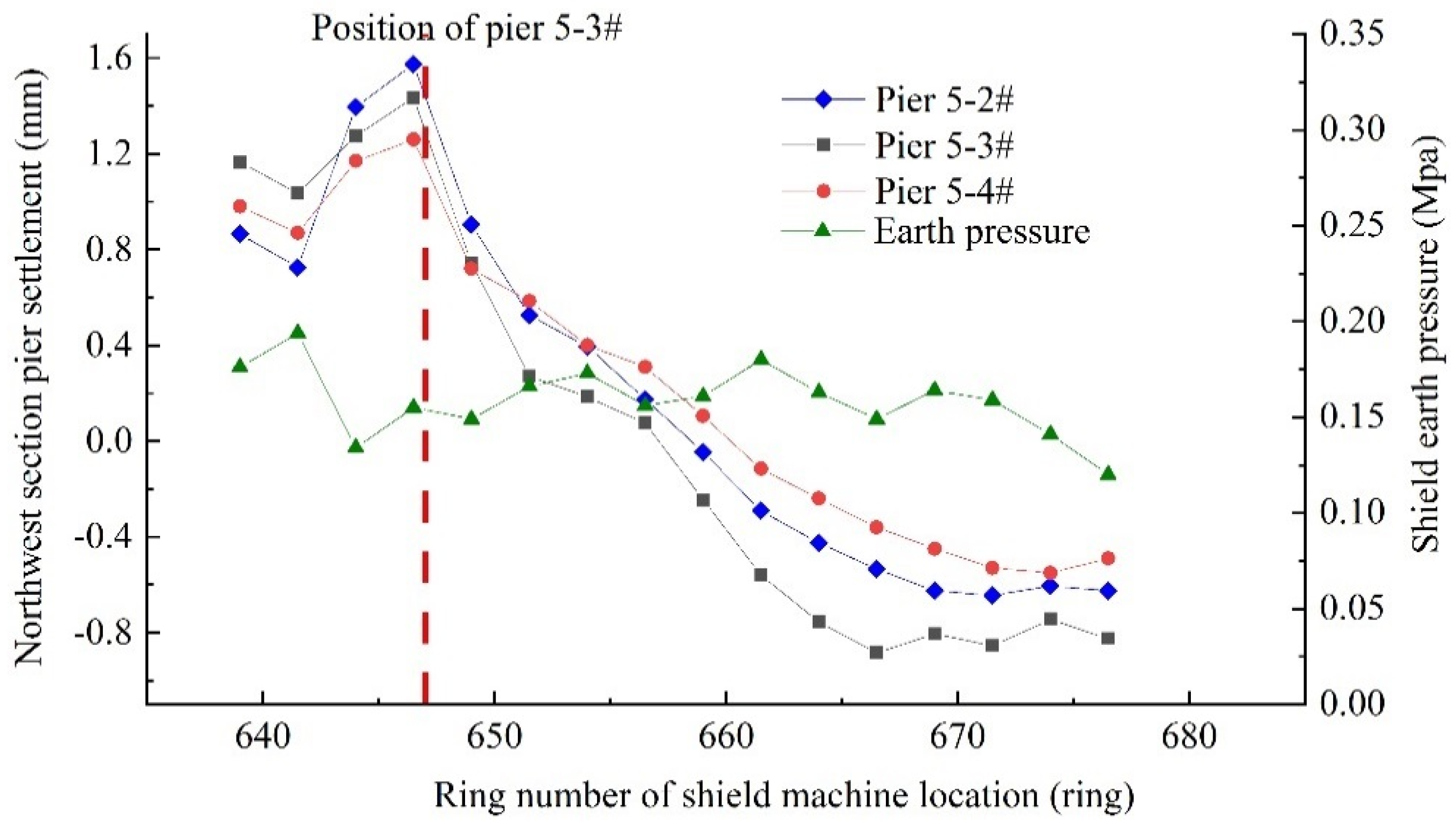
- (1)
- Fluctuation of the shield excavation face pressure at the northeast and northwest sections is small, so the settlement laws of the piers are similar, and the settlements are small.
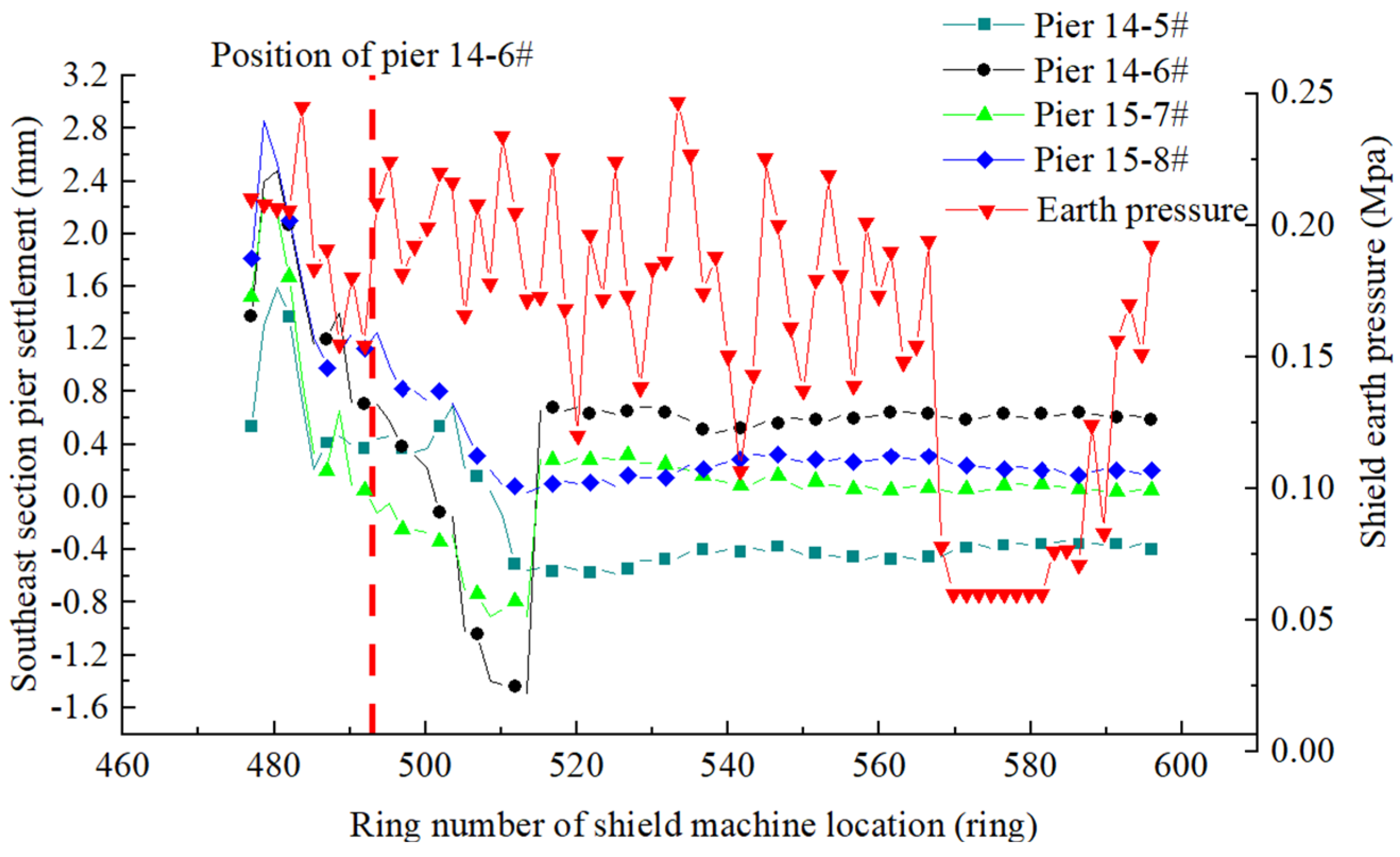
- (2)
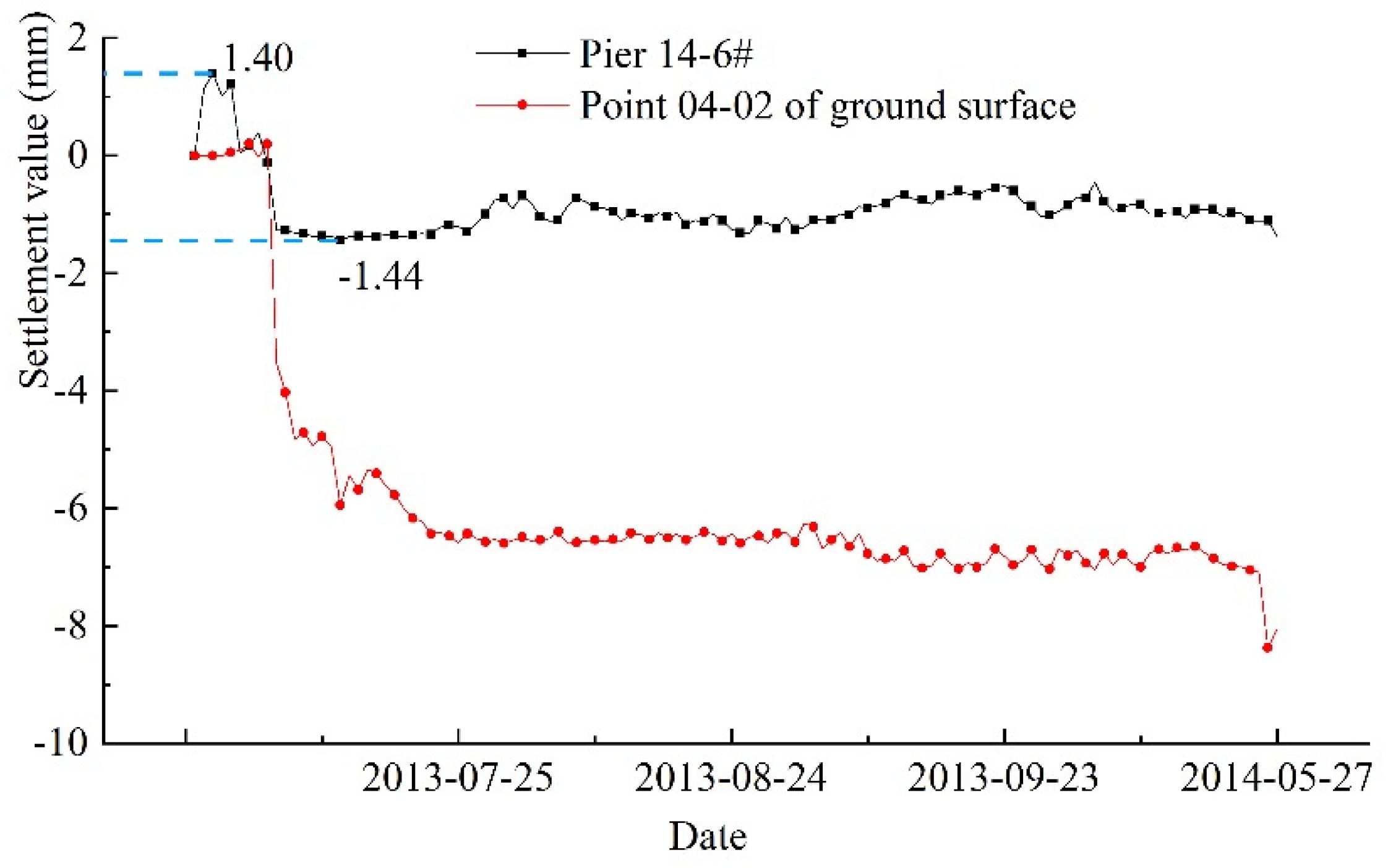
- The pier in the southeast section has a large settlement and a large earth pressure fluctuation during shield tunneling. The settlement of piers 14-6# and 15-7# reached a pre-warning value (1.5 mm), and then jacking was started. Using pier 14-6# as an example, the settlement reached 1.44 mm when the shield tunneling reached 517 rings, and the irregular-plate was jacked up by 2.0 mm.
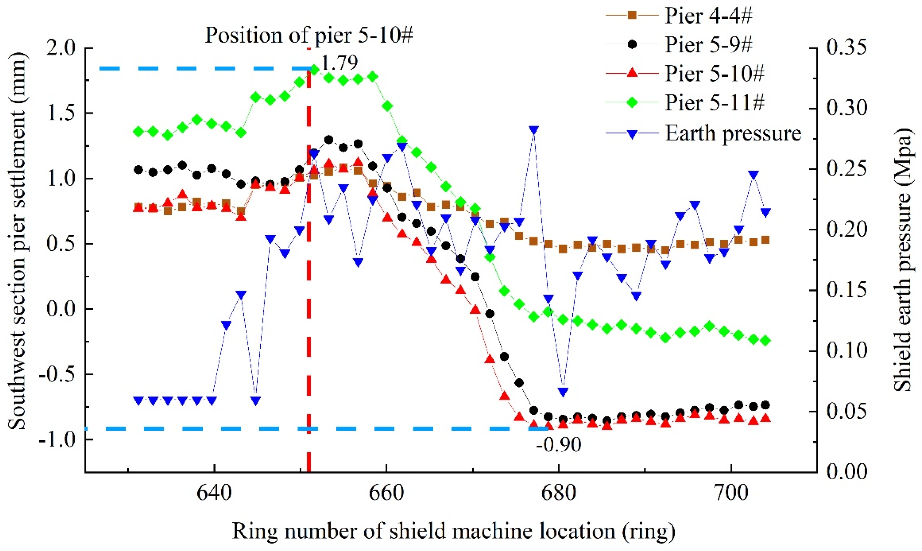
- (3)
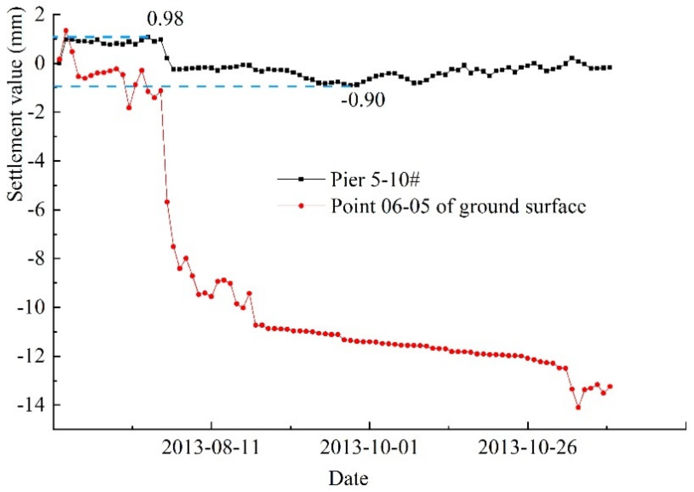
- Excavation face pressure fluctuation during shield tunneling in the southwest section is the largest, and an obvious increase in excavation face pressure leads to a further heave in the pile foundation. The maximum heave value of pier 5-11# reaches 1.79 mm. After the shield tunnel passed, the pile foundation rapidly settles, and the maximum settlement of pier 5-10# is 0.9 mm.
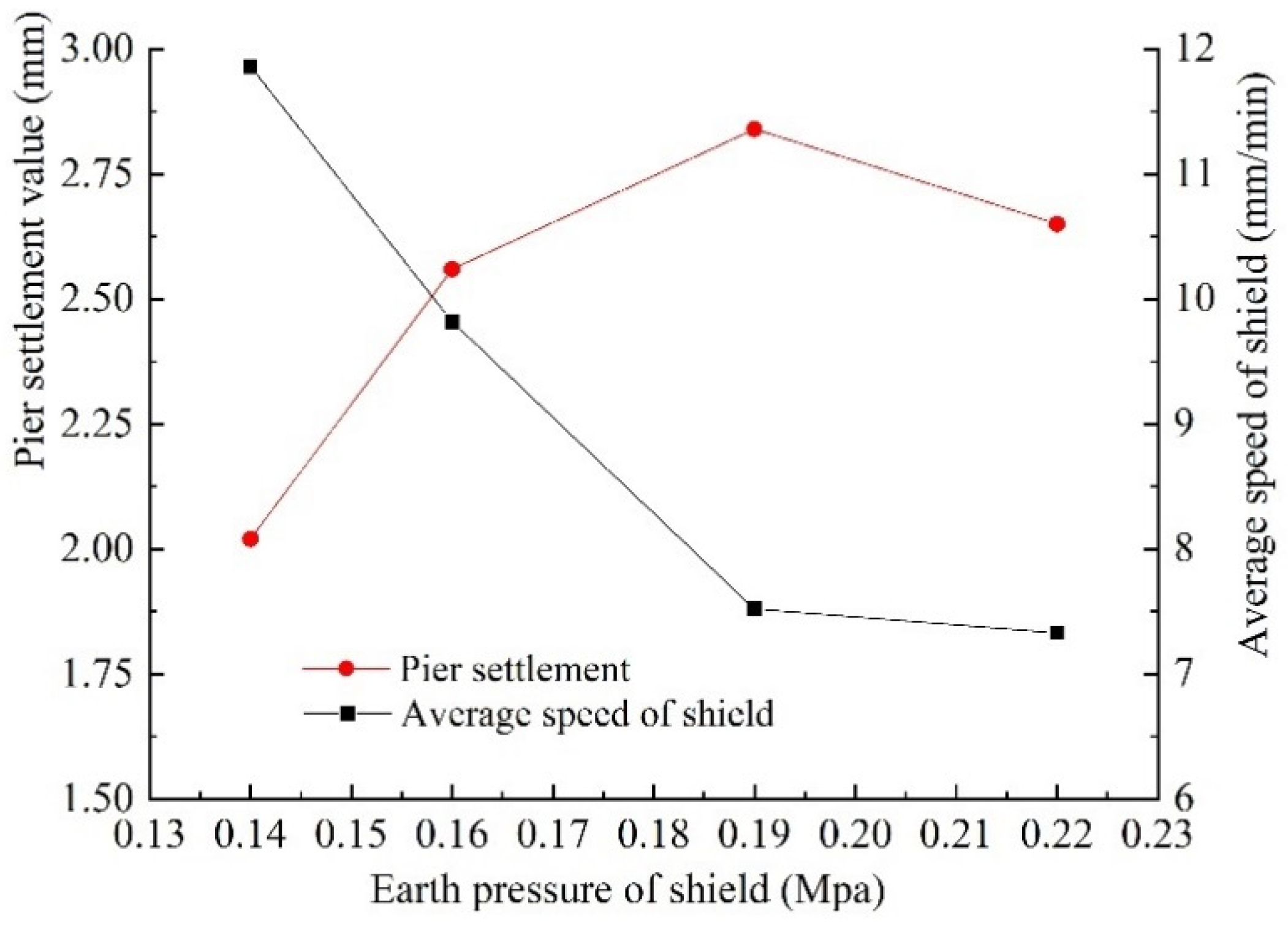
- (4)
- Pier settlement in the southeast section is the largest of the four underpass sections. With an increase in excavation face pressure, the settlement of pier in the southeast increases, and there are certain differences from the results of numerical calculation. From analysis, the main reason for the difference is that the excavation face pressure obviously increases during the shield underpass, and this results in the large torque of the cutter head and lower excavation speed. Thus, the disturbance time to the outer layer of the tunnel increases. The large loss of ground stress causes an increase in pier settlement.
6.2. Settlement Control Results of Pile Foundation and Its Corresponding Ground Surface
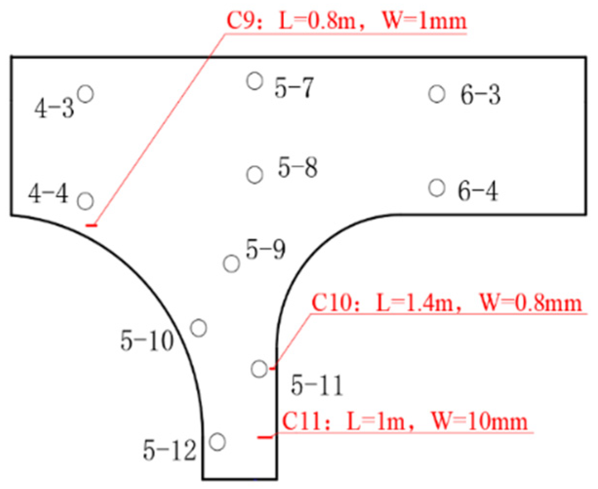
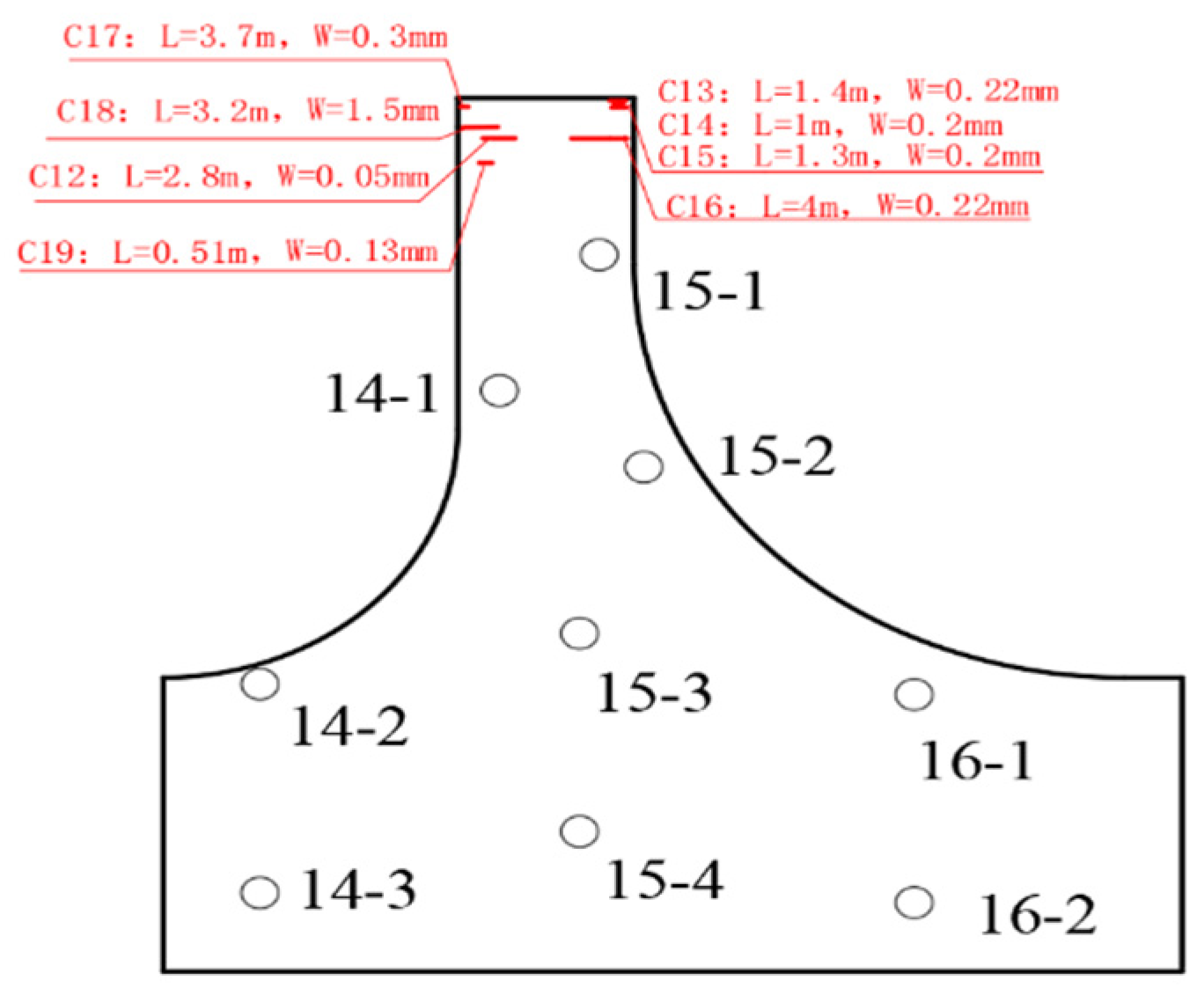
6.3. Control Results of Settlement and Cracking of the Irregular-Plate
7. Conclusions
- (1)
- Theoretical analysis shows that when the foundation settlement of the IPB reaches 3mm, the stress at the bottom of the irregular-plate will exceed the tensile strength of concrete, and this will cause some cracks at the bottom of the irregular-plate. During the tunnel construction, reasonable measures were taken to control the settlement of the foundation, which does not exceed 2 mm, and there are few cracks at the bottom of the irregular-plate. This indicates that the settlement control standard of the Midas civil program simulation analysis is basically reasonable. The reason for the deviation of the analysis is that the concrete structure generates temperature stress and shrinkage stress during use, and the distribution of these stresses is discrete, so it is difficult for MIDAS to analyze these stresses.
- (2)
- Excavation face pressure always fluctuates during shield excavation. It should be ensured that excavation face pressure is always kept above the minimum value, and this can provide that the regular-plate bridge is in a safe state during the process of the subway tunnel passing. When excavation face pressure is too high, excavation speed will decrease, and this will increase the disturbance of the stratum and the settlement of the bridge piles. Therefore, the unearthed volume should be increased in time to reduce excavation face pressure and to speed up shield excavation.
- (3)
- Synchronous jacking technology can be used for effectively controlling the great risks of a shield tunnel passing through the IPB. When settlement of the pier reaches 80% of the control value, the active jacking was used in time to compensate for the settlement of the irregular-plate, and this prevents the irregular-plate from cracking.
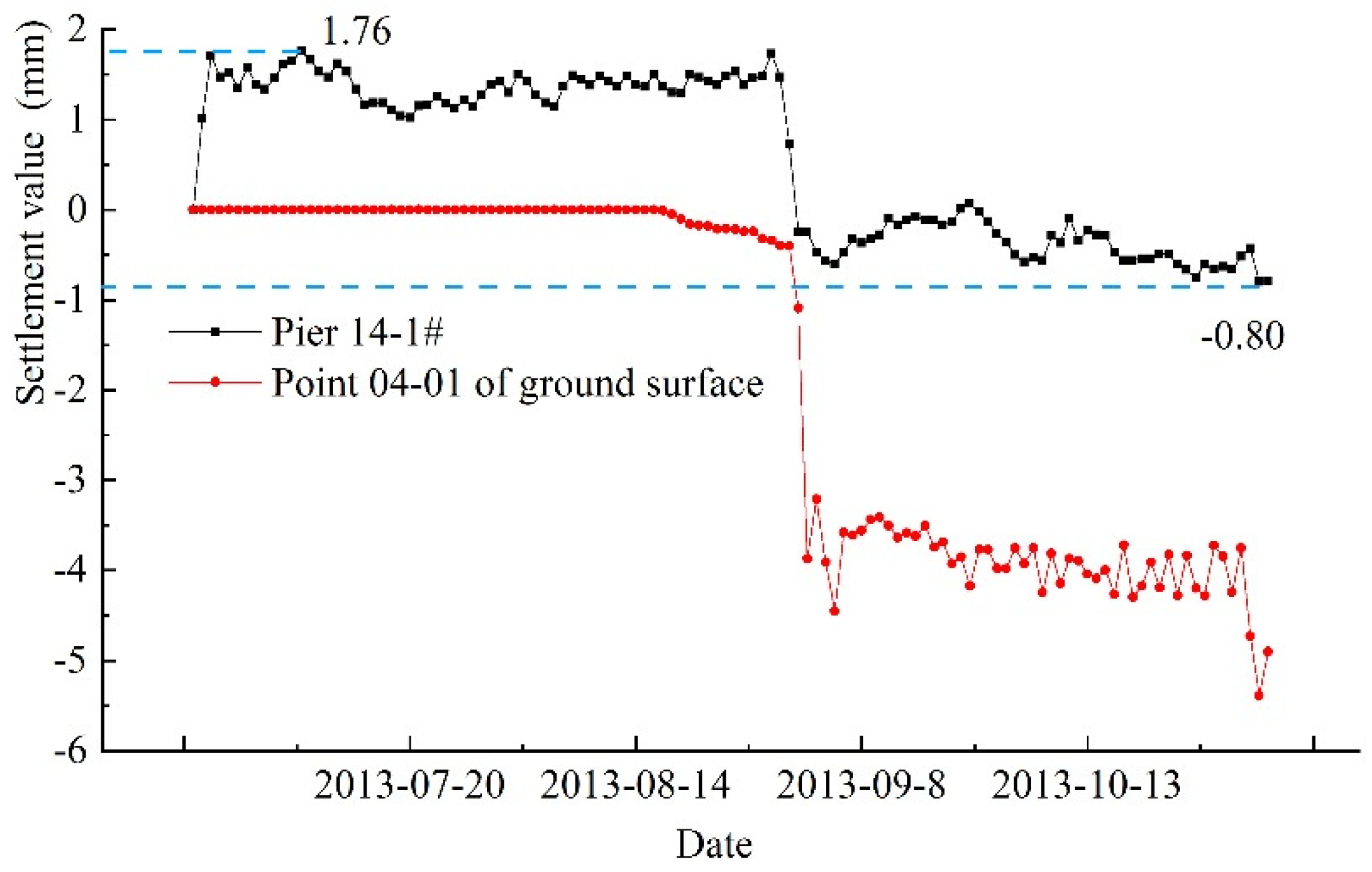
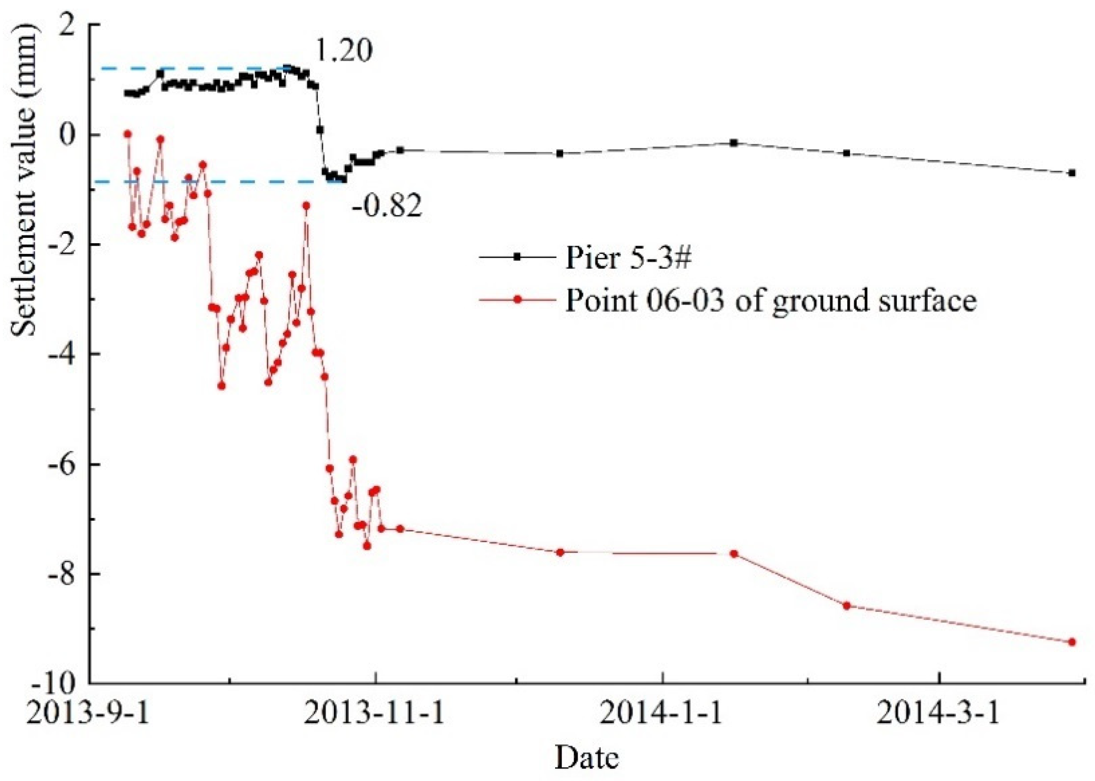
- (4)
- Pier settlement and ground surface settlement caused by shield tunnel being excavated have similar laws, but ground surface settlement is larger and has a longer time effect.
Author Contributions
Funding
Conflicts of Interest
References
- Ministry of Transport of the People’s Republic of China (MTPRC). China Code for Design of Ground Base and Foundation of Highway Bridges and Culverts (JTG D63-2007); MTPRC: Beijing, China, 2007.
- Ministry of Housing and Uran-Rural Development of the People’s Republic of China (MOHURD). China Code for Metro Design (GB 50157-2013); MOHURD: Beijing, China, 2013.
- Poulos, H.G. Behavior of Laterlly Loaded Piles: 3-socketed pile Groups. J. Soil Mech. Found. Div. 1972, 98, 341–360. [Google Scholar]
- Makarchian, M.; Poulos, H.G. Simplified Method for design of underpinning piles. J. Geotech. Eng. 1996, 122, 745–751. [Google Scholar] [CrossRef]
- Chen, L.T.; Poulos, H.G.; Loganathan, N. Pile responses caused by tunneling. J. Geotech. Geoenviron. Eng. 1999, 125, 207–215. [Google Scholar] [CrossRef]
- Mroueh, H.; Shahrour, I. Three-dimensional finite element analysis of the interaction between tunneling and pile foundations. Int. J. Numer. Anal. Methods Geomech. 2002, 26, 217–230. [Google Scholar] [CrossRef]
- Yang, X.J.; Deng, F.H.; Wu, J.J.; Jian, L.I.U.; Wang, F.Q. Response of carrying capacity of piles induced by adjacent Metro tunneling. Min. Sci. Technol. 2009, 19, 176–181. [Google Scholar] [CrossRef]
- Lognathan, N.; Poulos, H.G.; Stewart, D.P. Centrifuge model testing of tunnelingduced ground and pile deformation. Geotechnique 2000, 50, 283–294. [Google Scholar] [CrossRef]
- Cheng, C.Y.; Dasari, G.R.; Leung, C.F.; Chow, Y.K.; Rosser, H.B. 3D numerical study of tunnel-soil-pile interaction. Tunn. Undergr. Space Technol. 2004, 19, 381–382. [Google Scholar]
- Cheng, C.Y.; Dasari, G.R.; Chow, Y.K.; Leung, C.F. Finite element analysis of tunnel–soil–pile interaction using displacement controlled model. Tunn. Undergr. Space Technol. 2007, 22, 450–466. [Google Scholar] [CrossRef]
- Xiang, Y.; Jiang, Z.; He, H. Assessment and control of metro-construction induced settlement of a pile-supported urban overpass. Tunn. Undergr. Space Technol. Inc. Trenchless Technol. Res. 2007, 23, 89–95. [Google Scholar] [CrossRef]
- Goldsworthy, H.; Siddique, U.; Gravina, R. Support settlement and slabs reinforced with low-ductility steel. ACI Struct. J. 2009, 106, 840–847. [Google Scholar]
- Gilbert, R.I.; Sakka, Z.I. Strength and ductility of reinforced concrete slabs containing welded wire fabric and subjected to support settlement. Eng. Struct. 2010, 32, 1509–1521. [Google Scholar] [CrossRef]
- Tao, D.; Zhen-chang, G.; Kai-liang, C.; Li-yong, L. Simplified calculation of jacking load in active underpinning of bridge piles. Rock Soil Mech. 2015, 36, 3259–3267. [Google Scholar]
- Fang, Q.C.; Shang, L.; Shang, Y.H.; Zhao, Y.; OU, N.Y. Study on the reinforcement measures and control effect of the surrounding rock stability based on the shield tunneling under overpass structure. J. Eng. Sci. Technol. Rev. 2016, 9, 131–138. [Google Scholar] [CrossRef]
- Sun, F. Research on the optimal technology of active underpinning for pile foundation in shield tunneling building. J. Railw. Eng. Soc. 2018, 35, 93–97. [Google Scholar]
- Shen, Z. Further Discussion on Design and Calculation of “Beam-less Special-shaped Slab Bridge”. Spec. Struct. 2013, 30, 6–12. [Google Scholar]
- Itasca Consulting Group, Inc. FLAC3D: Theory and Background; Itasca Consulting Group, Inc.: Minneapolis, MN, USA, 2009. [Google Scholar]


| Bridge Type | Stress Characteristics of Bridge Structure | Bridge Control Point | Control Standard for Bridge Deformation |
|---|---|---|---|
| Simply supported beam bridge | The superstructure of a bridge is statically-determinate, the force is clear and simple, and settlement of the bearing will not cause additional stress in the superstructure. | Control the damage of bridge deck joints. | The differential settlement of the adjacent pier should not make the beam form an additional longitudinal slope greater than 0.12%, which is generally 20 mm [1,2]. |
| Continuous beam bridge | The superstructure of a bridge is statically-indeterminate, and there is a negative bending moment at the middle support. The differential settlement along the bridge increases the negative bending moment and generates additional stress. | Control the cracking of the main beam and reduce the loss of structural safety and durability. | The differential settlement of adjacent pier foundations shall be calculated according to the stress of the structure, generally within 8 mm [2]. |
| IPB | The superstructure of a bridge is statically-indeterminate, and the distribution of internal forces is complex. The interaction of the bending moment and torsion makes the superstructure have the characteristics of spatial force, and settlement in all directions produces additional stress. | Control the cracking of the bridge plate and reduce the loss of structural safety and durability. | Settlement of each pier foundation should be controlled within 3 mm. |
| Construction Steps | Main Construction Contents | Preliminary Risk Analysis | Importance |
|---|---|---|---|
| Working procedure I | Conduct a shield construction test to find out effective excavation parameters that meet the settlement control value of the IPB. | Synchronous jacking is difficult to achieve without effective stratum settlement control technology. | Critical working procedure |
| Working procedure II | Punch from the ground to the bottom of the pile, and then use grouting to strengthen the pile foundation. | An auxiliary measure is used to improve the bearing capacity of the stratum around the pile foundation before excavation of the shield tunnel. | Noncritical working procedure |
| Working procedure III | Install jacking equipment such as jacking supports and jacks; debug synchronous jacking equipment with an accuracy of 0.5 mm. | The active compensation of irregular-plate settlement and accuracy control is very important. | Noncritical working procedure |
| Working procedure Ⅳ | Shield tunneling is linked with synchronous jacking information to restore the spatial location of the irregular-plate in time. When the maximum settlement of piers exceeds 80% of the control value, the jacking is started. | Timeliness is crucial. | Slightly critical working procedure |
| Working procedure V | Real-time monitoring of the elevation of the plate bottom during jacking; measuring accuracy is 0.1mm. | Timeliness is crucial. | Slightly critical working procedure |
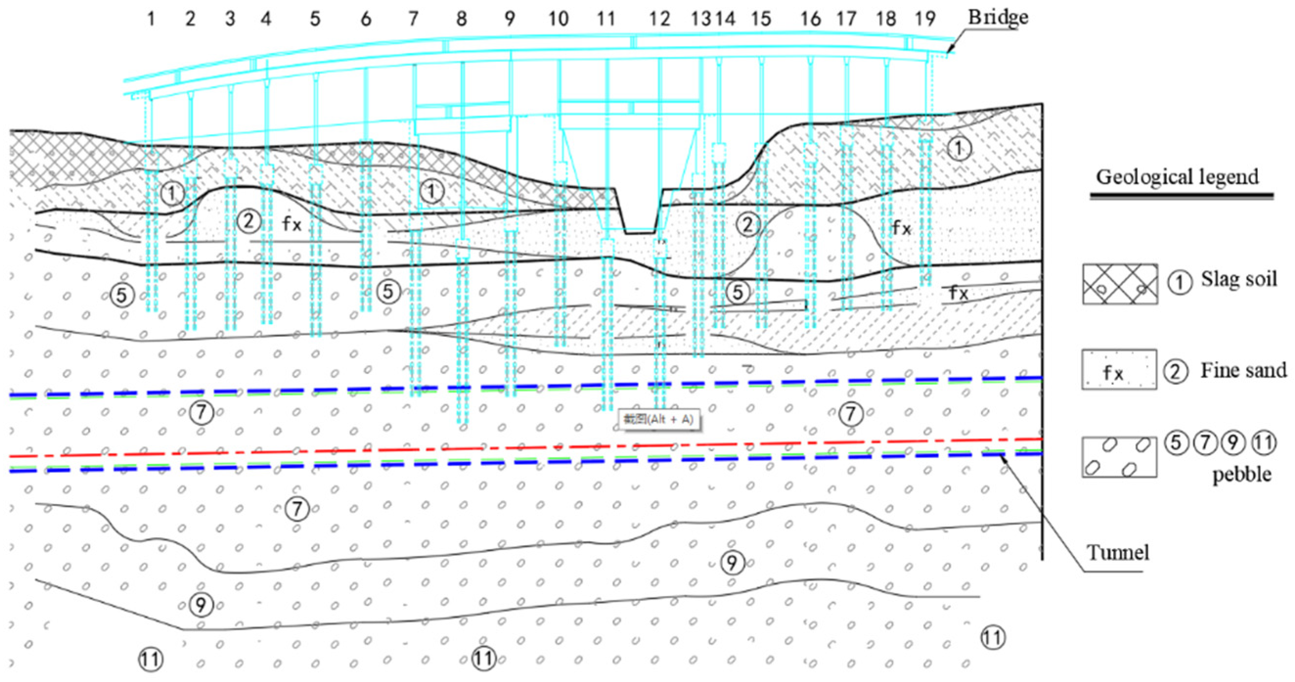
| Name of Soil Layer | Density (g/cm3) | Compressive Modulus (MPa) | Poisson’s Ratio | Cohesion (kPa) | Internal Friction Angle (°) | Thickness (m) |
|---|---|---|---|---|---|---|
| Artificial filling | 1.65 | 6 | 0.4 | 5 | 10 | 2 |
| Silt, clay | 2.0 | 7.5 | 0.31 | 30 | 10 | 8 |
| Fine sand | 2.0 | 30 | 0.26 | 0 | 35 | 6 |
| Roundstone, pebble | 2.05 | 65 | 0.2 | 0 | 40 | 10 |
| Pebble | 2.10 | 75 | 0.2 | 0 | 45 | 24 |
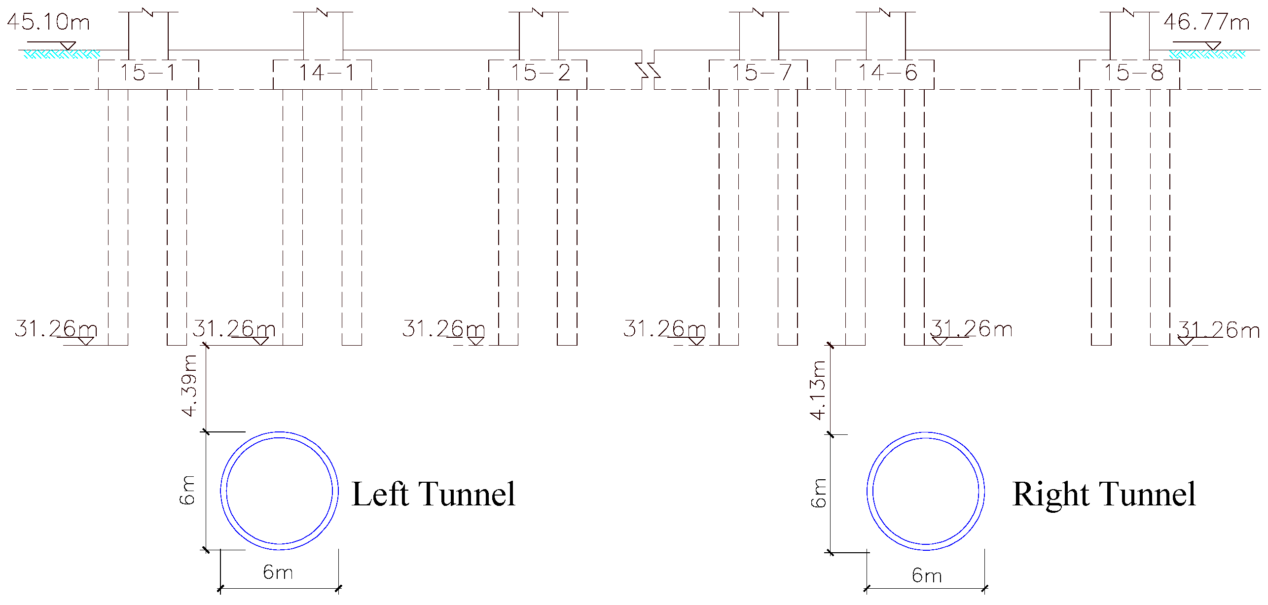
| Material Name | Density (g/cm3) | Elastic Modulus (MPa) | Poisson’s Ratio | Dimension (m) |
|---|---|---|---|---|
| Pier | 2.5 | 30,000 | 0.2 | 1.2 × 0.9 |
| Cushion cap | 2.5 | 30,000 | 0.2 | 5 × 5 and 5 × 2 |
| Pile | 2.5 | 30,000 | 0.2 | D = 1 |
| Segment | 2.5 | 24,150 | 0.2 | 0.3 m Thickness |
| Grouting layer material (soft) | 2.1 | 180 | 0.25 | 0.15 m Thickness |
| Grouting layer material (hard) | 2.1 | 1,800 | 0.2 | 0.1 5m Thickness |
| Pile bottom underpinning layer | 2.1 | 2,000 | 0.2 | 10 × 10 × 9 |
| Excavation Face Pressure | Working Condition 1 | Working Condition 2 | Working Condition 3 | Working Condition 4 |
|---|---|---|---|---|
| Upper part of excavation face (MPa) | 0.03 | 0.06 | 0.09 | 0.12 |
| Bottom part of excavation face (MPa) | 0.14 | 0.17 | 0.20 | 0.23 |
| Average excavation face pressure (MPa) | 0.085 | 0.115 | 0.145 | 0.175 |
| Construction Parameters | Pier Number | |||
|---|---|---|---|---|
| 5-3# | 14-1# | 14-6# | 5-10# | |
| Shield average earth pressure (MPa) | 0.14 | 0.16 | 0.19 | 0.22 |
| Shield average speed (mm/min) | 11.86 | 9.82 | 7.52 | 7.33 |
| Pier settlement (mm) | 2.02 | 2.56 | 2.84 | 1.88 |
| Settlement | Pier Number | |||
|---|---|---|---|---|
| 14-6# | 5-10# | 14-1# | 5-3# | |
| Pier (mm) | 2.84 | 1.88 | 2.56 | 2.02 |
| Ground surface (mm) | 8.05 | 13.24 | 5.5 | 9.24 |
| Different Stages | Pier Number | |||
|---|---|---|---|---|
| 14-6# | 5-10# | 14-1# | 5-3# | |
| Pile foundation grouting heave stage (mm) | +1.4 | +0.98 | +1.76 | +1.2 |
| Pile foundation settlement stage (mm) | −2.84 | −1.88 | −2.56 | −2.02 |
| Construction completion stage (mm) | +0.56 | −0.90 | −0.80 | −0.82 |
© 2019 by the authors. Licensee MDPI, Basel, Switzerland. This article is an open access article distributed under the terms and conditions of the Creative Commons Attribution (CC BY) license (http://creativecommons.org/licenses/by/4.0/).
Share and Cite
Hu, Y.; He, P. Risk Control Standard and Construction Control Technology of Shield Tunnel Passing through Irregular-Plate Bridge. Symmetry 2019, 11, 1331. https://doi.org/10.3390/sym11111331
Hu Y, He P. Risk Control Standard and Construction Control Technology of Shield Tunnel Passing through Irregular-Plate Bridge. Symmetry. 2019; 11(11):1331. https://doi.org/10.3390/sym11111331
Chicago/Turabian StyleHu, Yougang, and Ping He. 2019. "Risk Control Standard and Construction Control Technology of Shield Tunnel Passing through Irregular-Plate Bridge" Symmetry 11, no. 11: 1331. https://doi.org/10.3390/sym11111331
APA StyleHu, Y., & He, P. (2019). Risk Control Standard and Construction Control Technology of Shield Tunnel Passing through Irregular-Plate Bridge. Symmetry, 11(11), 1331. https://doi.org/10.3390/sym11111331