Article

Dynamic Modeling and Experiment Research on Twin Ball Screw Feed System Considering the Joint Stiffness

1
School of Mechanical and Electronic Engineering, Wuhan University of Technology, Wuhan 430070, China
2
School of Mechanical Science and Engineering, Huazhong University of Science and Technology, Wuhan 430070, China
*
Author to whom correspondence should be addressed.
Symmetry 2018, 10(12), 686; https://doi.org/10.3390/sym10120686
Submission received: 29 October 2018 / Revised: 9 November 2018 / Accepted: 16 November 2018 / Published: 1 December 2018
(This article belongs to the Special Issue Symmetry and Dynamical Systems)

Abstract

:
It is of great significance to study the dynamic characteristics of twin ball screw (TBS) feed system to improve the precision of gantry-type dual-driven computer numerical control (CNC) machine tools. In this paper, an equivalent dynamic model of the TBS feed system is established utilizing lumped mass method considering the stiffness of joints. Equivalent axial stiffness of screw-nut joints and bearing joints are both calculated by Hertz contact theory. Furthermore, a friction model is proposed because the friction force of the screw nut affects the stiffness of the joints. Then, the friction parameters are obtained by using the nonlinear system identification method. Meanwhile, a finite element model (FEM) is developed to assess the dynamic characteristics of TBS feed system under the stiffness of joints. Finally, validation experiments are conducted, and the results show that the positions of the nut and the velocities of worktable greatly affect the dynamic characteristics of the TBS feed system. Compared with the theoretical calculation, FEM and experiments indicate that the dynamic modeling proposed in this article can reach a higher accuracy.

1. Introduction

Twin ball screw (TBS) redundant feed system has been widely used in precision computer numerical control (CNC) equipment with high accuracy, high rigidity and high stability. Its dynamic characteristics have great effects on the control performance and machining precision and stability [1]. This configuration can also improve the control bandwidth, speed and accuracy for large gantry-type machine tools, so studying the dynamic characteristics of the TBS system plays an important role in improving the positioning and machining accuracy [2,3,4,5,6]. As per the platform shown in Figure 1a, it is considered beneficial to drive the worktable of a large single feed axis with two ball screws/motors which are arranged in parallel to provide a joint thrust in the same direction. This would significantly increase the rigidity of system and overall thrust for driving the stage. Although this layout has potential advantages, it does not come without additional concerns.
For the TBS system, much of the performance is applied as important indexes which are always of concern by engineers and researchers, such as nature frequencies, tracking errors, positioning accuracy and non-synchronous errors. In the design phase, in order to investigate and predict the dynamic characteristics as accurately as possible for machine tools, a volume of dynamic models have been proposed in research. García-Herreros I et al. [7] established a lumped parameter model of ETEL gantry-type dual-driven worktable using the Lagrange’s equation, but the simplified model ignored the joint stiffness and damping. Experiments show that the model’s non-synchronous error is large. Liu Y [8] established the second-order wave equation based on the transmission chain of single screw fixed form under different static and dynamic stiffness of the model. The correctness of the model was verified through experiments, but the model of the bearing components was equivalent to rigid bodies without considering the joint stiffness of the supporting bearing. John EH et al. [9] found that the elastic interaction between the machine tool and the specimen greatly affects the stiffness of machine tool through theoretical calculation and more than 200 tests. Li YX et al. [10] have studied the reasons of non-synchronous error in the TBS system on gantry-type machine tools and proposed a synchronous control model based on dynamical theory which described the influence of mechanical coupling and biaxial friction characteristics on non-synchronous error. The experiment verifies friction force has a great effect on dynamic characteristics. Cheng Y et al. [11] developed the dynamic model of the translational and torsional pendulum motion of the TBS system using the motion superposition method and obtained the influence of the system’s construction parameters such as stiffness ratio, friction damping ratio and the movement of the center of gravity of the mechanical coupling part on the non-synchronous error. Xie LM et al. [12] studied the load movement and transmission stiffness of cross beam of gantry-type machine tool and obtained the quantitative relationship between the displacement of cross beam load center of gravity and the system stiffness on the non-synchronous error of the TBS feed system. However, all the literature above didn’t consider the joint stiffness of the contact surface and process parameters including the displacement, velocity, acceleration etc., which seriously affect the dynamic characteristics.
Many research suggests that approximately 60% of the total dynamic stiffness and about 90% of the total damping of the entire machine tool structure originates in the joints [13,14,15]. Therefore, it is very important to study the joint stiffness of the transmission chain joints of the TBS system. There are so many theoretical research methods on studying the joint stiffness and damping, such as Hertz Contact theory, Takashi Yoshimura theory and Virtual Material theory etc. Zhang HJ et al. [16] used the lumped mass method to establish dynamic model of high speed feed system considering the joint stiffness, calculated the joint stiffness by using Hertz contact theory, and discussed the effect of different factors consisting of axial force, friction force and preload on stiffness of the transmission chain, but these conclusions were not extended to the TBS system. Chen et al. [17] developed a dynamic model of the high-speed ball screw feed system. The screw-nut joint is equivalent to a constant linear spring in the model. Zhu JM et al. [18] obtained the fixed and rolling joints stiffness of the feed system by Takashi Yoshimura and Hertz contact theory, respectively, and established a finite element model (FEM). The result shows high accuracy of the model.
Apart from the above factors which affect the dynamic characteristics of the TBS system greatly, the coupling force caused by the effect of the coupling beam is also important. Yao WS et al. [19] constructed a dynamic model of the controlled servo mechanism by using the multi-variable identification method considering the mechanical coupling of twin parallel-axis linear servo mechanism. It can be concluded that synchronous control of high speed machining with mechanical coupling can be achieved by the proposed system model. In this paper, the mechanical coupling is considered, and the coupling force is decoupled as the screw-nut friction force. Meanwhile, the friction model is proposed, and the model parameters are obtained through nonlinear system identification.
Obviously, the state of the machine tools varies with the machining process. The different states will lead to different static and dynamic characteristics of the machine tools. FEM and Modal test are both popular methods to predict the static and dynamic characteristics. Altintas et al. [20] summarized the use of finite element analysis of the dynamic behavior of machine tools in a review. Brussel HV et al. [21] studied the dynamics of a three-axis machine tool by using FEM and found that it possessed position-dependent dynamics. Modal test based on experiments can be further divided into experimental modal analysis (EMA) and operational modal analysis (OMA). All these researches above have made great contributions to the understanding of the dynamic characteristics of a ball screw feed system. However, most of the researches are about the dynamic modeling of a single ball screw system, and few are about the dynamic characteristics of the TBS system. In this paper, the EMA of worktable at different positions and the OMA of worktable at different speeds are both conducted without any load.
The nature frequency is an important performance index of the TBS system, and the system bandwidth and the anti-jamming property can be improved by increasing it [22]. Dynamic models are commonly used to analyze the nature frequency. In this paper, the proposed model and FEM are applied in the analysis of the 1st order nature frequency. This paper reveals that joint stiffness and friction force of screw-nut have great effects on dynamic characteristics of the TBS feed system. Therefore, a lumped dynamic model for studying the transmission stiffness of the TBS feed system is established.
Meanwhile, a friction model is proposed to study the influence of the friction force on screw-nut joint stiffness. In order to conduct experiments, a tested worktable with twin ball screws and dual linear guides are constructed. The axial stiffness of the supporting bearings and the double pre-tightening nut is tested. The vibration tests are carried out to measure the first nature frequency of the TBS system, and the relationship between friction force and the first nature frequency is obtained. Finally, contrastive analysis between the experimental results and the simulated results of three models is conducted. The results show that the proposed model agrees significantly moreso with the experimental results than the discrete model and hybrid model do.

2. Dynamic Model of the TBS System

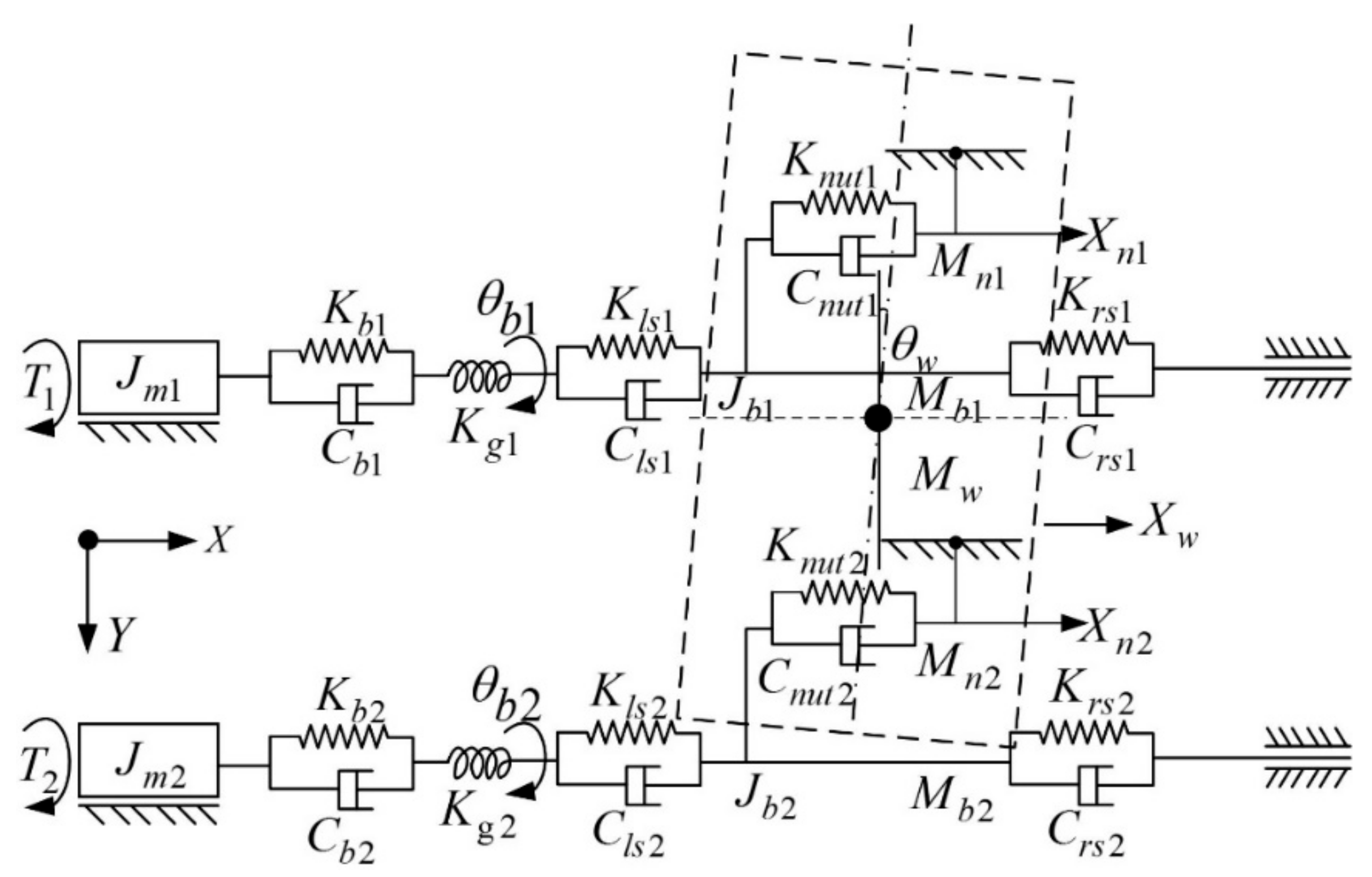
2.1. Dynamic Equivalent Model of the TBS System

Figure 1b shows the two-dimensional dual-driven worktable studied in this paper, the X and Y directions adopt dual-driven structure, which improves the transmission rigidity of the two-feed direction. Taking X direction as an example, the typical structure mainly consists of dual servo motors, twin ball screws, dual linear guide rails, bearings, worktable and other parts.
The transmission stiffness of the worktable depends on the stiffness of the dual flexible screw pairs and the joints, including the fixed joint and rolling joint. The fixed joint consists of worktable-slider joint and guide-bed joint which are connected by bolts. The rolling joint contains a screw-nut joint, bearing joint and guide-slider joint. Many studies [15] indicate that radial stiffness has little effect on the overall stiffness, therefore, the axial stiffness of the feed system is only considered in this paper.
Due to coupling of the worktable, the preload between screw and nut varies with coupling force and determines the screw-nut joint stiffness. The coupling force is mainly caused by friction force of the screw-nut joint, so the effect of friction between the screw and nut should not be neglected. In order to carry out research easily, the friction between the guides and sliders is not considered. In this section, a nonlinear friction model is developed, which deduces the relationship between the worktable speed and friction force, and the influence of speed on dynamic characteristics of the TBS system is further discussed.
In the equivalent dynamic model as shown in Figure 2, the screw, the screw-nut joint and the bearing joint are equivalent to spring damping elements. The worktable is equivalent to a lumped mass model. In the case of ignoring the influence of servo system stiffness, the transmission stiffness of the TBS system depends on joint stiffness.
Where, C b 1 and C b 2 are the damping of the bearings of the twin axes. K l s 1 , K r s 1 and C l s 1 , C r s 1 are the equivalent stiffness and damping of the left and right sides of the X 1 shaft’s nut, respectively. K l s 2 , K r s 2 and C l s 2 , C r s 2 are the equivalent stiffness and damping of the left and right sides of the X 2 shaft’s nut, respectively. K n u t 1 , K n u t 2 and C n u t 1 , C n u t 2 are the screw-nut joint stiffness and damping of the X 1 and X 2 shaft, respectively.

2.2. Dynamic Modeling of the TBS System

Figure 2 shows the model of the TBS feed system which can be formulated based on Lagrange’s energy method [23,24,25]. First, the kinetic energy of the system can be computed as follows:
T = 1 2 M w X ˙ w 2 + 1 2 ( M n 1 X ˙ n 1 2 + M n 2 X ˙ n 2 2 ) + 1 2 ( J m 1 + J b 1 ) θ ˙ b 1 2 + 1 2 ( J m 2 + J b 2 ) θ ˙ b 2 2 + 1 2 J w θ ˙ w 2
The potential energy of the feed system is given by
V = 1 2 · K n 1 ( X n 1 X w ) 2 + 1 2 · K n 2 ( X n 2 X w ) 2 + 1 2 · K a 1 ( X n 1 p θ b 1 ) 2 + 1 2 · K a 2 ( X n 2 p θ b 2 ) 2   + 1 2 · ( K g 1 θ b 1 2 + K g 2 θ b 2 2 ) + 1 2 · ( K w 1 + K w 2 ) θ w 2
Let L = T V , and
d d t ( T q ˙ i ) T q i + V q i = Q i
The general coordinates and general forces are defined as
q = ( q 1 q 2 q 3 q 4 q 5 q 6 ) T = ( X n 1 X n 2 X w θ n 1 θ n 2 θ w ) T
Q = ( Q 1 Q 2 Q 3 Q 4 Q 5 Q 6 ) T = ( F a 1 F a 2 0 T 1 T 2 0 ) T
where, F a 1 , F a 2 are the axial forces of the twin ball screw, respectively. T 1 , T 2 are the output torque of the dual servo motor, respectively.
The dynamic equation of the system can be expressed matrix form [26].
M q ¨ + C q ˙ + K q = Q
where, M , C and K are, respectively, the mass matrix, damping matrix, and stiffness matrix of the system. For simplifying analysis, the case is considered without damping.
M = [ M n 1 M n 2 M w J m 1 + J b 1 J m 2 + J b 2 J w ]
K = [ K n 1 + K a 1 0 K n 1 p K a 1 0 0 0 K n 2 + K a 2 K n 2 0 p K a 2 0 K n 1 K n 2 K n 1 + K n 2 0 0 0 p K a 1 0 0 p 2 K a 1 + K g 1 0 0 0 p K a 2 0 0 p 2 K a 2 + K g 2 0 0 0 0 0 0 K w 1 + K w 2 ]
Table 1 lists the parameters and related values used in the model. In this paper, the first order mode is mainly studied. It’s obvious that the first and second modes are from axial vibration, and the third mode is from torsional vibration. Therefore, the torsional stiffness of the TBS system is neglected. Eigenvectors can be studied to clarify the modeling. Many other parameters are obtained in the next section.

3. Transmission Stiffness Modeling of the TBS System

In this section, the calculation of the stiffness of the screw-nut joints and bearing joints and contact parameters identification are discussed.

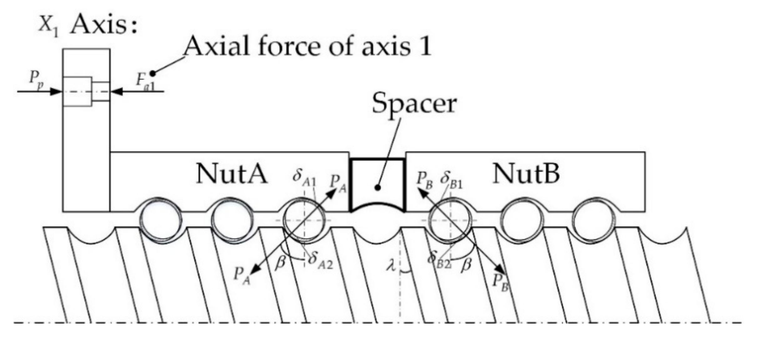
3.1. Calculating the Axial Stiffness of Screw-Nut Joints

3.1.1. Calculating the Stiffness of the Screw-Nut Joints

The ball screw pair is mainly composed of ball screw, nut and other parts. In order to eliminate the axial gap and improve the axial contact stiffness of the ball screw, the double-nut pretension structure is adopted in this paper. As shown in Figure 3, the double nut is composed of nut A and nut B which are connected by an elastic spacer. The elastic spacer can provide preload by elastic deformation. Assuming that the contact between the ball and the raceway obeys Hertz contact theory [27], therefore, the screw-nut joint stiffness can be calculated by Hertz contact theory. The ball screw used in this paper is HIWIN FDW20-5B2, and its basic parameters are shown in Table 1. Without considering the influence of the axial force of the screw, we can get Equation (7).
{ P A = P B = P p N sin β cos λ = P p ( i π d d b cos λ ) sin β cos λ δ A i = δ B i = M 1 · P A 2 3 , M 1 = 2 K i π a i { 1 8 [ 3 2 ( 1 μ 1 2 E 1 + 1 μ 2 2 E 2 ) ] 2 } 1 3 ( ρ i ) 1 3 , ( i = 1 , 2 ) δ A = δ A i , δ B = δ B i
The synthetic curvature of the contact point between the ball and the raceway is:
{ ρ 1 = 2 d b + 2 d 1 d b f 1 2 cos β cos λ d + d b cos β ρ 2 = 2 d b + 2 d 1 d b f 2 2 cos β cos λ d d b cos β
The axial deformation of the screw nut and the axial stiffness of the joints can be obtained from the geometric relation and Hooke’s law:
{ δ A a x = δ B a x = δ A sin β cos λ = M 1 [ P p 2 ( i π d d b cos λ ) 2 sin 5 β cos 5 λ ] 1 3 K n u t A = K n u t B = P p δ A a x = M 1 1 [ P p ( i π d d b cos λ ) 2 sin 5 β cos 5 λ ] 1 3
where, P p is the axial preload of ball screw, P A and P B are the normal forces between the ball and the nut A and B of the screw, respectively. N is the number of working balls and, N = i · π d / d b cos λ . i is the total number of load bearing ring of the single nut. d and d b are the nominal diameter and ball diameter of the ball screw, respectively. And β is the contact angle between the raceway and the ball. λ is the helix angle of the ball screw. K i and a i are Hertz coefficients, which can be obtained from the literature [28]. δ A 1 and δ A 2 are the contact deformation of the nut A. Similarly, δ B 1 and δ B 2 are the contact deformation of the nut B. μ 1 , μ 2 and E 1 , E 2 are the Poisson’s ratio and elastic modulus of ball and screw, respectively. Where, μ 1 = μ 2 = 0.3 , E 1 = E 2 = 210   GPa . f is the tightness of the ball screw.

3.1.2. Calculating the Axial Stiffness of Screw-Nut Joints Caused by Friction Force

In the process of the worktable movement, the screw-nut joint stiffness varies with the displacement and velocity of the worktable due to coulomb friction and axial force influence between the screw and nut. As shown in Figure 4, F a 1 and F a 2 are the axial forces of the axis 1 and axis 2, respectively. When the worktable is in uniform motion, the axial force of the screw depends on the friction force of the screw nut. According to the second law of Newton, the Equation (10) is obtained as follows:
( F a 1 f ( v 1 ) ) + ( F a 2 f ( v 2 ) ) = M a
When a = 0 , the axial force of the screw is equal to the friction force. Furthermore, the friction model is established and the relationship between the friction force and the output torque is [29]:
{ f ( v ) = [ F c + ( F s F c ) e ( v / v s ) 2 ] sgn ( v ) + d e l t v T o u t P T 2 π p f ( v ) = 0
where, T o u t and P T , P T = 0.90 are the output torque and efficiency of the motor, respectively. In the uniform motion of the worktable, there is F i = f ( v i ) , i = 1 , 2 . Take axis 1 as the main axis, and the axis 2 as the slave axis. When the velocity of worktable is in the range of 0–50 mm/s, the output torque of the dual motors is synchronously measured. The relationship between the friction force of the screw nut and the velocity of worktable can be obtained by the nonlinear identification method. As shown in Figure 4, the nonlinear fitting curves of the friction force and the velocity are given. Table 2 shows the friction model parameters of two axis obtained by nonlinear identification.
Considering the friction force of the screw nut, the Equation (12) can be obtained:
{ P A T = P A + F a 1 = P p + F a 1 N sin β cos λ = P p + F a 1 ( i π d d b cos λ ) sin β cos λ δ A T = M 1 P A T 2 3
Similarly, the axial deformation of the nut A and the joint stiffness can be obtained:
{ δ A T a x = δ A T sin β cos λ = M 1 [ ( P p + F a 1 ) 2 ( i π d d b cos λ ) 2 sin 5 β cos 5 λ ] 1 3 K n u t A T = P p + F a 1 δ A T a x M 1 [ ( P p + F a 1 ) ( i π d d b cos λ ) 2 sin 5 β cos 5 λ ] 1 3
According to the coordination condition of elastic deformation, the deformation relation of nut A and nut B is given by Equation (14):
δ A T δ A = δ B δ B T
Therefore, the contact deformation of nut B:
{ δ B T = 2 δ A δ A T , ( δ A T < 2 δ A ) 0 , ( δ A T 2 δ A )
As it can be seen from the above Equation (15) that when δ A T 2 δ A , the contact deformation of the nut B is 0, which causes a sharp change of the screw-nut joint stiffness. Similarly, the equivalent axial contact stiffness of the nut B is:
K n u t B T = { M 1 1 [ 2 P p 2 3 ( P p + F a 1 ) 2 3 ] 1 2 [ ( i π d d b cos λ ) 2 sin 5 β cos 5 λ ] 1 3 , ( δ A T < 2 δ A ) 0 , ( δ A T 2 δ A )
Then the equivalent axial stiffness of screw nut of the axis 1 depends on the larger value of K n u t A T and K n u t B T , expressed as:
K n u t 1 = max { K n u t A T , K n u t B T }

3.1.3. Calculating the Axial Stiffness of the Bearing Joints

Figure 5 shows the bearing assembly used in this paper. The ball screw is mounted with one end fixed and one end free, so the fixed end with a pair of angular contact ball bearings can bear axial force. The deep groove ball bearings with only supporting functionality are used at the other end of the screw. Therefore, the axial stiffness can be ignored. F p and α are the preload and contact angle of the angular contact bearing, respectively. Table 3 shows the basic parameters of the angular contact bearings used in this paper. The normal force and axial deformation of a single ball can be obtained by Hertz contact theory.
{ P = F p z sin α δ b i = M 2 P 2 3 , ( i = 1 , 2 ) , M 2 = 2 K i π a i { 1 8 [ 3 2 ( 1 μ 1 2 E 1 + 1 μ 2 2 E 2 ) ] 2 } 1 3 ( ρ i ) 1 3 δ a = ( δ b 1 + δ b 2 ) sin α
Therefore, the axial stiffness K 1 of a single bearing joint is:
K 1 = K 2 = F p δ a
Since the contact between the two angular contact ball bearings is in series, the stiffness of bearing joints K b 1 is:
K b 1 = ( 1 K 1 + 1 K 2 ) 1 = K 1 2
where, z is the number of balls, δ b 1 , δ b 2 are the contact deformation of the ball with the inner and outer rings, respectively.

3.1.4. Calculating the Transmission Stiffness of the Overall TBS System

As shown in Figure 2, the equivalent axial stiffness of the TBS system depends on the axial stiffness of the screw, the stiffness of the screw-nut joints and the bearing joints. On the left side of the nut, the angular contact bearings and the screw are in series. Thus, the equivalent axial stiffness of the left subsystem of the lead screw is:
{ K L = ( 1 K s l + 1 K b 1 ) 1 K s l = π d 2 E 4 x , ( 0 < x < L )
where, x is the length from the nut to the left side of the screw, and L is the working length of the screw. On the right side of the nut, the axial stiffness of the screw can be neglected. Furthermore, the left subsystem and the nut are in series, and axis 1 and axis 2 are in parallel. The axial stiffness of axis 1, K a 1 and X direction of the TBS worktable, K A x can be expressed as:
{ K a 1 = ( 1 K L + 1 K n u t A T ) 1 K A x = i = 1 2 K a i = 2 ( 1 K L + 1 K n u t A T ) 1 = 2 K s l K b 1 K s l + K b 1 K n u t A T ( K s l K b 1 K s l + K b 1 ) + K n u t A T , ( i , j = 1 , 2 )
Then, the equivalent axial stiffness K A x in the Y direction can be obtained in the same way. The stiffness of the X and Y direction is in series, and then the overall transmission stiffness of the two-dimensional TBS worktable is as follows [30]:
K = ( 1 K A x + 1 K A y ) 1

4. FE Analysis of the TBS Worktable

ANSYS finite element analysis software is applied to perform modal analysis of the TBS worktable. At first, the 3D geometry model of the TBS worktable is established in the 3D software Solidworks, and then imports it into ANSYS. In order to calculate conveniently, the model is simplified properly, and the features of the screw thread, the small holes, fillet etc., which have few influences on the dynamic characteristics, are neglected. Motors and other components that have few effects on calculation results are ignored. The solid model is modeled by Solid 186 unit. An automatic meshing method is used in ANSYS to divide the solid model. And the Combine 214 spring elements are used to simulate the stiffness of the screw-nut joints, the bearing joints and the guide-slider joints, ignoring the stiffness and damping of the fixed joints. This section mainly studies the finite element analysis of the TBS worktable considering the dynamic stiffness of the joints.

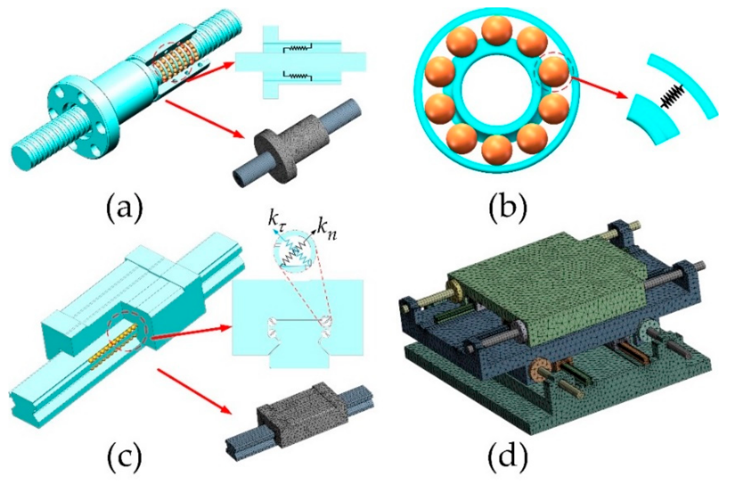
4.1. Modeling of the FEM

4.1.1. FEM of the Screw-Nut Joints

As shown in Figure 6a, the equivalent stiffness of screw-nut joints is taken as springs. Four springs are arranged along the circumferential direction of the screw. The stiffness of each spring is equal to 1/4 of the stiffness of screw-nut joints. In order to reduce the number of mesh and improve the calculation efficiency, the structure of screw and nut is simplified, so the FEM is obtained. The equivalent axial stiffness of screw-nut joints, K n u t = 1.28 × 10 8 N / m can be deduced by the third section.

4.1.2. FEM of the Bearing Joints

As shown in Figure 6b, similarly, the equivalent stiffness of bearing joints is seen as springs. Four springs are arranged along the circumferential direction of the bearing. The stiffness of each spring is also equal to 1/4 of the stiffness of bearing joints. The equivalent axial stiffness, K b = 4.2 × 10 7 N / m can be similarly drawn from the former section, the FEM of the bearing can be obtained by simplifying the ball.

4.1.3. FEM of the Guide-Slider Joints

As shown in Figure 6c, the material of the guide is steel 55, the Young modulus, E = 206 GPa. The density is 7800 kg/m3, and the Poisson’s ratio is 0.3. The equivalent stiffness of the guide-slider joints is taken as springs, and the damping effect is ignored. The dynamic model and FEM are established, and the equivalent normal stiffness and tangential stiffness of the guide-slider joints are K n = 3.2 × 10 7 N / m and K τ = 1.2 × 10 7 N / m , respectively. The two parameters can be calculated by the third section.

4.1.4. FEM of the TBS Worktable

The FEM of the entire TBS worktable is shown in Figure 6d. In the ANSYS, the boundary conditions are set. The bottom surface of the worktable is fixed. The joint stiffness among all components is set, which is obtained by the above value. The method of structured grid combined with unstructured grid is used to divide the mesh size to 2 mm.

4.2. Finite Element Analysis of the TBS Worktable

By solving and analyzing the FEM, the first order nature frequencies of the worktable can be obtained at different positions. As shown in Table 4, the nature frequencies obtained by the FE analysis are larger than that obtained by experiments because the stiffness of the fixed joints is ignored in FE analysis. The overall stiffness is larger than the actual; so are the nature frequencies. However, these will be improved in the following study. Block Lanczos method is used for modal solution in ANSYS when the worktable is located at the middle position of the stroke. Meanwhile, the vibration modes of two-dimensional TBS worktable are obtained.
Figure 7 shows the first four modes of the TBS worktable considering the stiffness of joints. The Figure 7a,b show the first and second low order translational vibration modes of the worktable in the Y and X direction, respectively. The Figure 7c shows the third vibration mode is high order yawing vibration of the worktable in the Z direction. The Figure 7d shows the fourth vibration mode is the pitching vibration of the worktable around Y axis.

5. Dynamic Experiments

The experimental study is carried out on the basis of theoretical calculation and FE analysis. According to the transmission stiffness model, the transmission stiffness of the TBS feed system is related to the position of the worktable. The modal tests of the worktable are carried out, because it is of great significance to determine the dynamic characteristics of the worktable at different positions for practical machining process.
As shown in Figure 1a, the worktable is bolted to the bed. The direction of X and Y are respectively driven by “dual servo motors + twin ball screws” to realize the linkage of two directions, and different contour trajectory. The parameters of the ball screw are shown in Table 1. Reference to the relevant information [31], the initial preload of the screw nut is (0.07~0.1) P d = 1.115   K N . A pair of angular contact ball bearings are mounted on the left end of the ball screw (model: FAG B7202CT P4S.UL), supporting and bearing the axial force and the worktable of the coupling force. The axial preload of the bearing, F p = 1   K N is applied to the bearing lock nut by means of a torque wrench. The relevant parameters are shown in Table 2.
The Econ dynamic analyzer is applied to test the dynamic characteristics of the worktable at different positions and velocities. As shown in Figure 8, four single axes accelerate sensors (model: BK4507B) are arranged at four corners with large vibration amplitude of the worktable. The impulse force hammer (model: DYTRAN 5800B5) is utilized by single point excitation multi-point vibration pickup method to conduct the experiments. Econ MI7008 acquisition card is employed to realize high-precision data acquisition. Data processing is carried out by Modal Genius software. The frequency response curve and mode shape are obtained by data fitting.

5.1. The Dynamic Characteristics of the Worktable at Different Positions

Because the transmission stiffness of the TBS system is related to the nut position, its dynamic characteristics will change when the nut position varies in the X and Y direction of the worktable. Figure 9 shows the relationship between the transmission stiffness of the worktable and the position of the nuts. The abscissa indicates the ratio of the nut position to the screw stroke, and the longitudinal coordinate is the overall transmission stiffness of the worktable. It can be seen from the Figure 9 that the overall transmission stiffness of the TBS system decreases with the increase of the nut position in the two directions. The transmission stiffness is maximum when the nut is located at the left end of the ball screw. Similarly, the nut at the right end of the transmission system shows the minimum transmission stiffness. So, the overall stiffness of the system is poor, which is not conducive to the processing operation. Therefore, the case that the nut is at the right end of the ball screw should be avoided in the actual processing, especially for high precision machine tools.
In order to make the experiment convenient and without losing generality, only the position variation of the nut in the X direction is taken into account in the experiment, and the nut is located at the middle point of the Y direction. Figure 10 shows the frequency response curves of the TBS worktable by experiments when the nut is located at different positions in the X direction. It can be seen from the curves that the first order nature frequency increases with the increase of the overall stiffness of the worktable.
From Table 5 and Figure 11, the first nature frequencies of the TBS worktable are very close when the nut is located at different positions because the screw stroke is too short. The theoretical calculation is closer to the experimental data, and the errors are basically within 10%, which verifies the correctness of the theoretical model. However, the FE analysis has larger errors than the experimental results do. The maximum error is up to 19.2% because the worktable structure is simplified properly in the process of establishing the FEM, such as damping, chamfer and small pore structure. These factors lead to big errors, but they will be improved in the future work.

5.2. The Dynamic Characteristics of the Worktable at Different Velocities

The stiffness of the screw-nut joints and the whole TBS system are changed due to the different friction characteristics of the screw nut at different velocities. For the convenience of research, the X direction of the system is taken as the research object, and the middle point of the screw stroke is selected as the reference position. In the process of the experiments, the master-slave synchronization control strategy is adopted in the TBS system. The axis 1 and axis 2 are regarded as the main axis and slave axis, respectively. The output velocity of the master serves as the velocity reference for the slaves.
The OMA reflects the dynamic characteristics of the machine tools under different working states. In the process of nonlinear friction force identification, the dynamic characteristics of nuts at the middle point of the ball screw at different velocities are studied, without external excitation, and the excitation is produced by the servo motor to drive the ball screw, which is called self-excited. The experimental device is shown in the last section.
The equivalent stiffness of the screw-nut joints, K n u t A T and K n u t B T at different velocities can be calculated by Equations (10)–(17). As shown in Figure 12, it can be seen that the stiffness of the screw-nut joints decreases with the increase of the velocity of the worktable, and the stiffness of the screw nut B reduces faster. When the velocity is 35 m/min, the stiffness of the screw nut A remains stable, but the stiffness of the screw nut B decreases sharply to 0. This is because the friction force of the screw nut B is equal to the driving force applied on the nut B at this velocity, which means that the velocity is the maximum critical velocity of the TBS system. Meanwhile, when the velocity exceeds 35 m/min, the nut B will fail and does not play the role in providing preload and eliminating clearance.
The equivalent stiffness of the bearing joints, K b under different velocities can be calculated by Equations (18)–(20). As shown in Figure 11, when the velocity is in the range of 0–30 m/min, the equivalent stiffness of the bearing joints decreases slowly. When the velocity is 30 m/min, the equivalent stiffness of the bearing joints is minimum. This is because the preload is equal to the axial force of the bearing. When the velocity exceeds 30 m/min, the stiffness of bearing joints increases rapidly because the axial force of the bearing is greater than the preload.
Figure 13 shows the frequency response curves at different velocities. It can be seen from the curves that when the velocity is in the range of 0–30 m/min, the first order nature frequency of the TBS system decreases because the overall stiffness of the TBS system is minimum at this time. Therefore, this velocity should be avoided in the actual machining process. Furthermore, when the velocity is over 30 m/min, the nature frequency of the system increases gradually due to the increase of the overall stiffness of the TBS system. By comparing Figure 10 and Figure 12, it is found that the dynamic nature frequency is higher than the static nature frequency.

6. Conclusions

This article considers the stiffness of the typical joints of the TBS feed system, takes the self-developed TBS two-dimension worktable as the research object, and establishes the equivalent transmission stiffness model of the TBS worktable. What’s more, the friction force model of the screw nut is proposed. Finally, the dynamic characteristics of the two-dimensional TBS worktable at different positions and at different velocities are studied, and the effectiveness of the model is verified by the experiments. The main conclusions of this article are as follows:
  • The lumped mass method and FE method were employed to establish the dynamic model of the TBS feed system considering the stiffness of screw-nut and bearing joints, and to build the stiffness model of the transmission chain. Furthermore, the calculation formulas of the static overall stiffness of the two-dimensional TBS system were deduced. It also gives the mapping relation between the overall stiffness and the position of the nut in the X and Y direction.
  • The equivalent stiffness model of the joints is established by using Hertz contact theory, and the stiffness of the screw-nut joints, bearing joints and guide-slider joints were calculated by it. Then, the calculation results of the joints’ stiffness were applied to the FEM. Compared with theoretical calculation and FE analysis, the maximum error is up to 19.2% because the stiffness of the fixed joints was neglected.
  • The dynamic characteristics of the worktable at different positions were studied, and the maximum error of the nature frequency of the system was 11.1%. Thus, the correctness of the theoretical model is verified by experiments. The overall stiffness of the TBS system decreases with the increase of the nut positions of X and Y direction. In actual machining process, the furthermost right side of the worktable should be avoided.
  • The dynamic characteristics of the worktable at different velocities are studied. Due to the friction force variations with the velocities, a friction model was proposed, and the parameters of the model were obtained through nonlinear system identification. The experiment showed that the maximum critical speed of the system is 35 m/min. When the velocity exceeds it, K n u t B T = 0 , the bearing will fail. When the velocity is 30 m/min, the stiffness of the bearing is minimum and the same as the overall TBS system. By comparing Figure 10 and Figure 13, it shows the dynamic nature frequency is larger than the static nature frequency.
The main implication of this paper was developing the transmission chain stiffness model and researching the EMA and OMA of the TBS feed system considering the stiffness of the joints, which will guide the dynamic design of the CNC machine tools. In further study, the stiffness of the fixed joints such as worktable-slider joints connected by bolts will be considered. The load and cutting force will also be considered. Furthermore, the dynamic characteristics at different accelerations will be studied.

Author Contributions

M.D. and H.L. conceived and designed the experiments; Q.L. performed the experiments; Y.Z. and Z.L. analyzed the data; X.Z. contributed reagents/materials/analysis tools; M.D. wrote the paper.

Funding

This research was funded by [The National Nature Science Foundation of China] grant number [51675393] and [The Major Projects of Technological Innovation of Hubei Province] grant number [2017AAA111].

Conflicts of Interest

The authors declare no conflicts of interest.

References

  1. Hsieh, M.F.; Yao, W.S.; Chiang, C.R. Modeling and synchronous control of a single-axis stage driven by dual mechanically-coupled parallel ball screws. Int. J. Adv. Manuf. Technol. 2007, 34, 933–943. [Google Scholar] [CrossRef]
  2. Altintas, Y.; Verl, A.; Brecher, C. Machine tool feed drives. CIRP Ann.-Manuf. Technol. 2011, 60, 779–796. [Google Scholar] [CrossRef]
  3. Li, F.; Jiang, Y.; Li, T. An improved dynamic model of preloaded ball screw drives considering torque transmission and its application to frequency analysis. J. Adv. Mech. Eng. 2017, 9. [Google Scholar] [CrossRef]
  4. Zhang, H. Dynamic analysis of the machine drive system. J. Mech. Sci. Technol. 2015, 29, 5205–5215. [Google Scholar] [CrossRef]
  5. Mi, L.; Sun, M.N.; Wang, X.H. Effects of preloads on joints on dynamic stiffness of a whole machine tool structure. J. Mech. Sci. Technol. 2012, 26, 495–508. [Google Scholar] [CrossRef]
  6. Hung, J.P. Load effect on the vibration characteristics of a stage with rolling guides. J. Mech. Sci. Technol. 2009, 23, 89–99. [Google Scholar] [CrossRef]
  7. García-Herreros, I.; Kestelyn, X.; Gomand, J. Model-based decoupling control method for dual-drive gantry stages: A case study with experimental validations. Contr. Eng. Pract. 2013, 21, 298–307. [Google Scholar] [CrossRef] [Green Version]
  8. Liu, Y.; Wang, J.; Zhao, T. Stiffness model for a ball screw drive system. J. Tsinghua Univ. 2011, 51, 601–606. [Google Scholar]
  9. John, E.H.; Peter, P.G. Mechanical testing machine stiffness: Part I—Theory and calculations. Int. J. Adv. Manuf. Technol. 1971, 13, 251–264. [Google Scholar]
  10. Li, Y.X.; Zhao, W.H.; Cheng, Y. Synchronous Control System Modeling of Gantry-Type Machine Tools. J Xi’an Jiao Tong Univ. 2012, 46, 119–124. [Google Scholar]
  11. Cheng, Y.; Liang, T.; Zhao, W.H. Non-synchronous Error and Modeling of Dual-drive System in Gantry-type Machine Tools with Travelling Bridge. J. Mech. Eng. 2013, 49, 174–182. [Google Scholar] [CrossRef]
  12. Xie, L.M.; Yang, X.Y. Non-synchronous error analysis of dual-driving feed system considering the change of the center of gravity of the load. Mod. Manuf. Eng. 2016, 1, 82–87. [Google Scholar]
  13. Wang, R.C. Research on Performance Analysis and Test of Twin Ball Screw Feed Machine Tool for Structural Dynamic Error. Ph.D. Thesis, Tsinghua University, Beijing, China, 2013. [Google Scholar]
  14. Zhu, J.M.; Zhang, T.C.; Wang, J. Axial dynamic characteristic parameters identification of rolling joints in a ball screw feed drive system. Proc IMechE, Part C J. Eng. Manuf. 2015, 220, 203–210. [Google Scholar] [CrossRef]
  15. Wang, D.Z.; Lu, Y.; Zhang, T.C. Effect of Stiffness of Rolling Joints on the Dynamic Characteristic of Ball Screw Feed Systems in a Milling Machine. Shock Vib. 2015, 2015, 1–11. [Google Scholar] [CrossRef]
  16. Zhang, H.J.; Zhang, J.; Liu, H. Dynamic modeling and analysis of the high-speed ball screw feed system. Proc. IMechE Part B J. En. Manuf. 2014, 229. [Google Scholar] [CrossRef]
  17. Chen, Y.; Tang, W. Determination of contact stiffness in ball screws considering variable contact angles. Proc. IMechE Part C J. Eng. Manuf. 2015, 228, 2193–2203. [Google Scholar] [CrossRef]
  18. Zhu, J.M.; Zhang, T.C.; Li, X.R. Dynamic Characteristic Analysis of Ball Screw Feed System Based on Stiffness Characteristic of Mechanical Joints. J. Mech. Eng. 2015, 2015, 51–17. [Google Scholar] [CrossRef]
  19. Yao, W.S.; Yang, F.Y.; Tsai, M.C. Modeling and Control of Twin Parallel-Axis Linear Servo Mechanisms for High-Speed Machine Tools. Int. J. Auto Smart Technol. 2011, 1, 77–85. [Google Scholar] [CrossRef]
  20. Altintas, Y.; Brecher, C.; Weck, M. Virtual Machine Tool. CIRP Ann. Manuf. Technol. 2005, 54, 115–138. [Google Scholar] [CrossRef]
  21. Brussel, H.V.; Sas, P.; Nemeth, I. Towards a mechatronic compiler. IEEE/ASME Trans. Mechatron. 2001, 6, 90–105. [Google Scholar] [CrossRef]
  22. Erkorkmaz, K.; Kamalzadeh, A. High bandwidth control of ball screw drives. CIRP Ann. Manuf. Technol. 2006, 55, 393–398. [Google Scholar] [CrossRef]
  23. Montgomery-Smith, S.; Huang, W. A Numerical Method to Model Dynamic Behavior of Thin Inextensible Elastic Rods in Three Dimensions. ASME J. Comput. Nonlinear Dyn. 2014, 9, 011015. [Google Scholar] [CrossRef]
  24. Fan, W.; Lu, H.; Zhang, X.B. Two-Degree-Of-Freedom Dynamic Model-Based Terminal Sliding Mode Control with Observer for Dual-Driving Feed Stage. Symmetry 2018, 10, 488. [Google Scholar] [CrossRef]
  25. Wang, N.G.; Cao, G.H. Modeling and Control for a Multi-Rope Parallel Suspension Lifting System under Spatial Distributed Tensions and Multiple Constraints. Symmetry 2018, 10, 412. [Google Scholar] [CrossRef]
  26. Peasgood, M.; Kubica, E.; McPhee, J. Stabilization of a Dynamic Walking Gait Simulation. ASME J. Comput. Nonlinear Dyn. 2007, 2, 65–72. [Google Scholar] [CrossRef]
  27. Kong, F.; Huang, W.; Jiang, Y. A Vibration Model of Ball Bearings with a Localized Defect Based on the Hertzian Contact Stress Distribution. Shock Vib. 2018, 2018, 1–14. [Google Scholar] [CrossRef]
  28. Cheng, G.R.; Shi, Z.K.; Zhang, C.P. Design Basis of Ball Screw Transmission; Machinery Industry Press: Beijing, China, 1987; pp. 79–80. [Google Scholar]
  29. Canudas, W.C.; Olsson, H.; Astrom, K.J. A new model for control of systems with friction. IEEE Trans. Automat. Contr. 1995, 40, 419–425. [Google Scholar] [CrossRef] [Green Version]
  30. Olvera, D.; Lacalle, L.N.L.D.; Fz-Valdivielso, A. Analysis of the tool tip radial stiffness of turn-milling centers. Int. J. Adv. Manuf. Technol. 2012, 60, 883–891. [Google Scholar] [CrossRef]
  31. Ball Screws’ Technical Information of HIWIN; Hiwin Technologies Corp.: Taichung, Taiwan, 2013.
Figure 1. (a) Dual-drive grinding wheel machine tools; (b) The 3D model of the TBS feed worktable.
Symmetry 10 00686 g001
Figure 2. Equivalent dynamic model of the TBS feed system of the X direction.
Symmetry 10 00686 g002
Figure 3. Cross-section view of a gasket-type double-nut ball screw joints.
Symmetry 10 00686 g003
Figure 4. Friction force and motor velocity curve of the TBS system. (a) Friction force and motor velocity curve of axis 1; (b) Friction force and motor velocity curve of axis 2.
Symmetry 10 00686 g004
Figure 5. Assembly structure of the support bearing units.
Symmetry 10 00686 g005
Figure 6. FEM of the TBS worktable. (a) FEM of the ball screw and nut; (b) FEM of the angular contact bearing; (c) FEM model of the linear guide; (d) FEM model of the whole TBS system.
Symmetry 10 00686 g006
Figure 7. The typical mode of the TBS system. (a) The first mode: linear vibration; (b) The second mode: linear vibration; (c) The third mode: yawing vibration; (d) The fourth mode: pitching vibration.
Symmetry 10 00686 g007
Figure 8. Dynamics measurement of the TBS feed system.
Symmetry 10 00686 g008
Figure 9. The transmission Stiffness of the dual-screw system.
Symmetry 10 00686 g009
Figure 10. Frequency response of the TBS system under the different nut position.
Symmetry 10 00686 g010
Figure 11. The 1st nature frequency of the TBS system at different nut position.
Symmetry 10 00686 g011
Figure 12. The equivalent stiffness of the joints.
Symmetry 10 00686 g012
Figure 13. Frequency response of the TBS system under the different velocity.
Symmetry 10 00686 g013
Table 1. Basic parameters of the screw-nut joints.
Num. of Bearing Balls N Ball Diameter d b / m m Contact Angle β / ( ) Preload P p / K N Helix Angle λ / ( ) Crowns f Nominal Diameter d / m m
983.175451.1154.54990.5220
Table 2. The coefficients of the friction model.
Coefficient F c ( N ) F s ( N ) d e l t v s ( m m / s )
Axis 1Axis 2Axis 1Axis 2Axis 1Axis 2Axis 1Axis 2
Value280.90431.40425.801225.003.495.100.420.30
Table 3. Basic parameters of the angular contact bearing.
Num. of Bearing Balls Z Ball Diameter   d 0 / m m Contact Angle   β / ( ) Preload   F p / k N Crowns   f
106.6401.00.52
Table 4. Parameters and related values used in modeling the TBS system.
ParametersGiven Value
M w : worktable mass24.43 kg
M n 1 , M n 2 : nut 1 and nut 2 mass0.575 kg
p: the lead of the ball screw5 × 10−3 m
J m 1 , J m 2 : inertial moment of the motor 1 and 21.76 × 10⁻⁴ kgm2
J b 1 , J b 2 : inertial moment of the ball screw 1 and 27.85 × 10⁻⁵ kgm2
J w : inertial moment of the worktable0.505 kgm2
X n 1 : axial displacement of the nut 1state variable
X n 2 : axial displacement of the nut 2state variable
X w : displacement of the worktablestate variable
θ n 1 : rotating angle of the screw 1state variable
θ n 2 : rotating angle of the screw 2state variable
θ w : twist angle of the worktablestate variable
Table 5. Comparison of theoretical calculation, finite element analysis and experiment.
Nut Position   x / L 1st Nature Frequency of Theoretical Calculation   f t h e / H z 1st Nature Frequency of Experiment   f exp / H z Error % 1 st   Nature   Frequency   of   FE   Analysis   f F E A / H z Error %
051.449.73.458.417.5
0.2550.948.35.457.619.2
0.550.347.65.756.017.6
0.7549.745.110.253.217.9
148.944.011.150.113.8

