1. Introduction
Massive MIMO is an emerging technology with potential spatial dimension resources by providing multiple antenna arrays (tens to hundreds or even thousands of antennas) at the base station with several orders of magnitude higher than existing multi-antenna systems, e.g., fourth-generation Long-Term Evolution-Advanced (LTE-A) [
1,
2,
3]. Users can achieve huge performance advantages in spectrum efficiency (SE), energy efficiency (EE), multi-user interference (MUI) cancellation, spatial resolution, and upper-layer scheduling without adding additional time, frequency, and power resources [
4,
5,
6,
7,
8,
9]. Because of this, it has attracted much attention from the wireless communication industry and research institutions, and is widely regarded as one of the key technologies of the physical layer of fifth-generation 5G systems [
7]. It is worth noting that these performance enhancements caused by massive MIMO technology are based on the premise that the base station (BS) obtains good channel state information (CSI) [
6,
7,
8,
9], and channel estimation, as an important part of acquiring CSI, will affect the performance of the entire system. For the two traditional duplex systems of communication systems, time division duplex (TDD) and frequency division duplex (FDD), the channel estimation scheme used by massive MIMO to obtain CSI and the generated pilot overhead are also very different [
6]. In the TDD system, as the uplink and downlink channels satisfy the reciprocity condition, the uplink pilot signal can be sent by the user, and the BS receives the channel and then performs channel estimation, thereby obtaining the downlink channel CSI. Therefore, the length of the orthogonal pilot sequence will be proportional to the number of users, and the pilot overhead is small regardless of the number of antennas [
8]. For the FDD system, as the uplink and downlink channels no longer satisfy reciprocity, the pilot sequence can only be transmitted by the BS, and the user performs channel estimation, and then the user feeds the CSI back to the BS. Thus, the length of the orthogonal pilot sequence will be proportional to the number of BS antennas, resulting in huge system overhead, which will cause huge waste of effective information transmission of the system [
8]. This is also an important reason for many researchers have put the main research into the TDD system at the beginning of the massive MIMO technology [
9,
10,
11,
12].
However, under the TDD system, pilot contamination, uplink and downlink channel calibration errors, and hardware impairments of massive MIMO systems seriously affect their performance. In the FDD system, the system can provide special advantages that are not found in TDD systems, such as low latency, symmetric services, and so on. [
13]. At the same time, in the current cellular communication system, the main duplex mode is still FDD. According to the 4G license issued by countries around the world, there are more than 300 licenses for the FDD system, and there are only more than 50 licenses for the TDD system [
14,
15]. Therefore, considering the smooth evolution and transition of 4G to 5G systems, it is of great theoretical and engineering significance to solve the pilot overhead problem in massive MIMO technology under FDD [
13,
14,
15,
16]. Therefore, industry and research institutions are gradually focusing on the research of massive MIMO FDD systems. Although CSI acquisition in massive MIMO FDD systems faces great difficulties, researchers have studied different aspects such as channel estimation scheme, pilot signal, quantization feedback, and precoding design, and obtained some preliminary results [
10,
11,
12,
13,
14,
15,
16].
In the work of [
16], in the dense user scenario, a two-dimensional precoding scheme for the reduced-dimensional channel based on channel statistics is proposed. The scheme utilizes the same or similar channel covariance matrix in dense users to group different users, and eliminates inter-group interference by orthogonality of inter-group channel covariance matrix, thereby reducing feedback overhead of channel estimation. The authors in [
17] proposed the low-overhead channel estimation and feedback scheme based on compressed sensing by minimizing the time-space two-dimensional sparsity of wireless channels. The authors in [
18,
19] studied the pilot signal optimization scheme based on the mean square error (MSE) minimization and the maximum received signal-to-noise ratio (
SNR) for the single-user massive MIMO FDD system. The authors in [
20] studied the low-overhead pilot signal and channel estimation scheme from the perspective of the wireless channel. However, the existing research on massive MIMO FDD systems mostly optimizes the design of pilot signals or precoding schemes under the condition of given pilot sequence length, and does not yet analyze the influence of pilot sequence length on system performance [
13,
14,
15,
16,
17,
19,
20]. Therefore, pilot sequence length is an important overhead indicator in massive MIMO FDD systems.
However, many studies on massive MIMO does not utilize orthogonal frequency division multiplexing (OFDM) technology with these systems. The addition of OFDM modulation with massive MIMO results in the same channel gain to each subcarrier and the entire bandwidth can be given to each terminal, which renders most physical layer control signaling redundant. Therefore, this paper makes full use of the sparse characteristics of the massive MIMO-OFDM channel, and proposes a compressed sensing (CS)-based block matching pursuit (BMP) algorithm that can better estimate the sparse basis and coefficients, which effectively estimates the channel and enhances the overall system performance.
The rest of the paper is organized as follows.
Section 2 describes the related work.
Section 3 provides the research problem.
Section 4 provides the system model.
Section 5 gives the simulation results and discussions, while
Section 6 concludes the paper.
2. Related Work
Massive MIMO is a novel wireless communication technology that uses a large number of antennas at the BS to serve a relatively small number of users in the same frequency band, thereby greatly improving the spectral efficiency of the system [
20,
21,
22,
23,
24]. In a massive MIMO system, the BS needs to use the downlink channel information for multiuser precoding, so it is critical to obtain accurate downlink channel information at the BS. When the system adopts the FDD mode, because there is no reciprocity between the uplink and downlink channels, the BS usually obtains downlink channel information by the following two steps: in step 1, the user performs downlink channel estimation according to the training sequence; and in step 2, the user-estimated channel information is fed back to the BS [
25].
However, in practice, the above processing method faces two difficulties: First, as the number of channel parameters increases sharply with the number of BS antennas, the time required for downlink channel estimation will also increase sharply, and may even exceed the coherence time of the system [
26], and, if pre-coded with outdated channel information, will undoubtedly greatly deteriorate the system performance. Second, as the estimated channel information needs to be fed back to the BS through limited feedback, when the channel parameters increase sharply, the system feedback overhead will also increase dramatically. Therefore, how to reduce the training overhead of downlink estimation and the feedback overhead of uplink feedback is a problem that must be solved in FDD massive MIMO systems. Studies have shown that large-scale channels have certain sparsity. The author in [
27] describes that, using the sparseness of the channel in the angle-domain, a joint-orthogonal matching pursuit (J-OMP) algorithm is proposed. The term angle-domain refers to the decomposition of the channel matrix into the basis matrix and the gain matrix and enables the separate estimation of the channel information and gain matrix. The non-zero value of the domain is estimated, and only non-zero values are fed back during the feedback process, thereby reducing the amount of feedback, but it does not address the problem that the channel estimation time may be too long. The term non-zero value refers to the channel elements that are beneficial in the channel estimation process; these are the scattered channel elements, which collectively indicate the sparsity of the channel. In the work of [
28], the distributed sparsity adaptive matching pursuit (DSAMP) algorithm is used to better estimate the non-zero value of the channel in the angle domain, but it assumes that the feedback channel is an additive Gaussian noise channel, which is a simplification of the real situation. The authors in [
29] compressed the observation of the sparseness of the channel under a certain dictionary matrix, and feed the dimensionality observations back to reduce the feedback amount. Designing the dictionary matrix to reduce the estimated mean square error (MSE) assumes that it is possible to obtain channel estimation without error, which is too ideal, and if the result of the channel estimation is affected by noise, the sparsity of this estimation results under the designed transform domain dictionary may disappear.
4. System Model
Consider a massive MIMO-OFDM system where the BS is configured with
antennas, and the number of system subcarriers is
. The channel from the BS to a certain user can be expressed as follows:
where
is the
th column of the matrix and represents the channel response of all antennas on the
th subcarrier, and
is the
th row of the matrix and represents the channel response of all subcarriers on the
th antenna.
According to the authors of [
9], the channel vector
can be expressed in the virtual angle domain as follows:
where
is the transformation matrix, that is, the virtual angle domain is determined by the antenna array structure at the BS. For example, when the BS employs a uniform linear array (ULA) and the distance between the antennas
(
is the signal wavelength),
is a conjugate of the discrete Fourier transform (DFT) matrix.
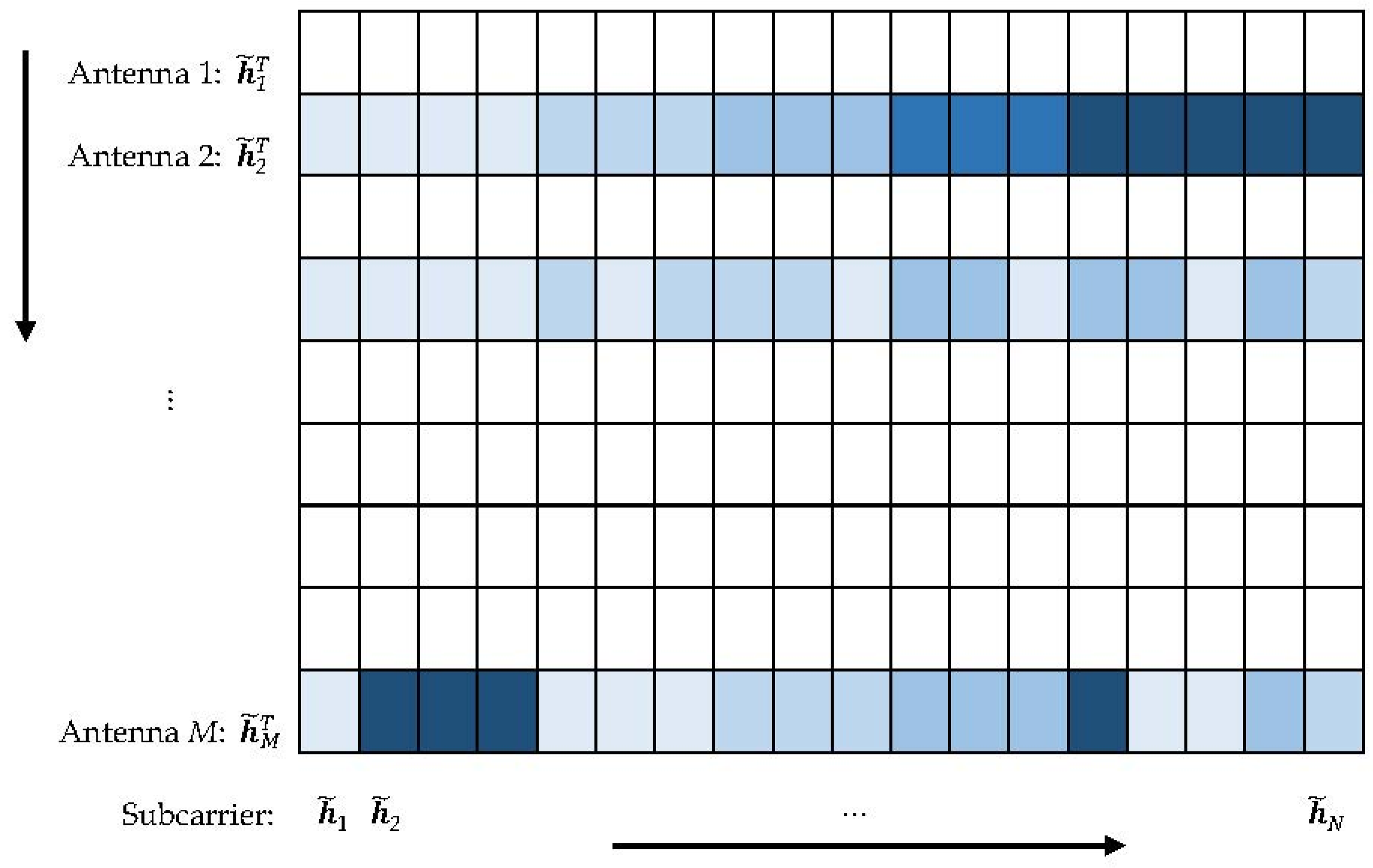
In massive MIMO systems,
will exhibit sparsity due to the limited downlink extension of the BS. Further, for massive MIMO-OFDM systems, the channel responses on different subcarriers will exhibit the same sparsity, that is, the locations of non-zero elements in all
are the same [
9] (see
Figure 1).
Which is the following:
where
. Straightening the matrices
and
, we can get the following:
In Equation (5),
indicates that the matrix is straightened by the column.
corresponds to the
th row of the sparse matrix in
Figure 1. According to Equations (3) and (4), the relationship between
and
is obtained as follows:
where
where
denotes Kronecker product. According to
Figure 1, the vector
has a block sparsity characteristic, that is,
contains
non-zero blocks, and each non-zero block contains
non-zero values, where
is the angular domain sparsity.
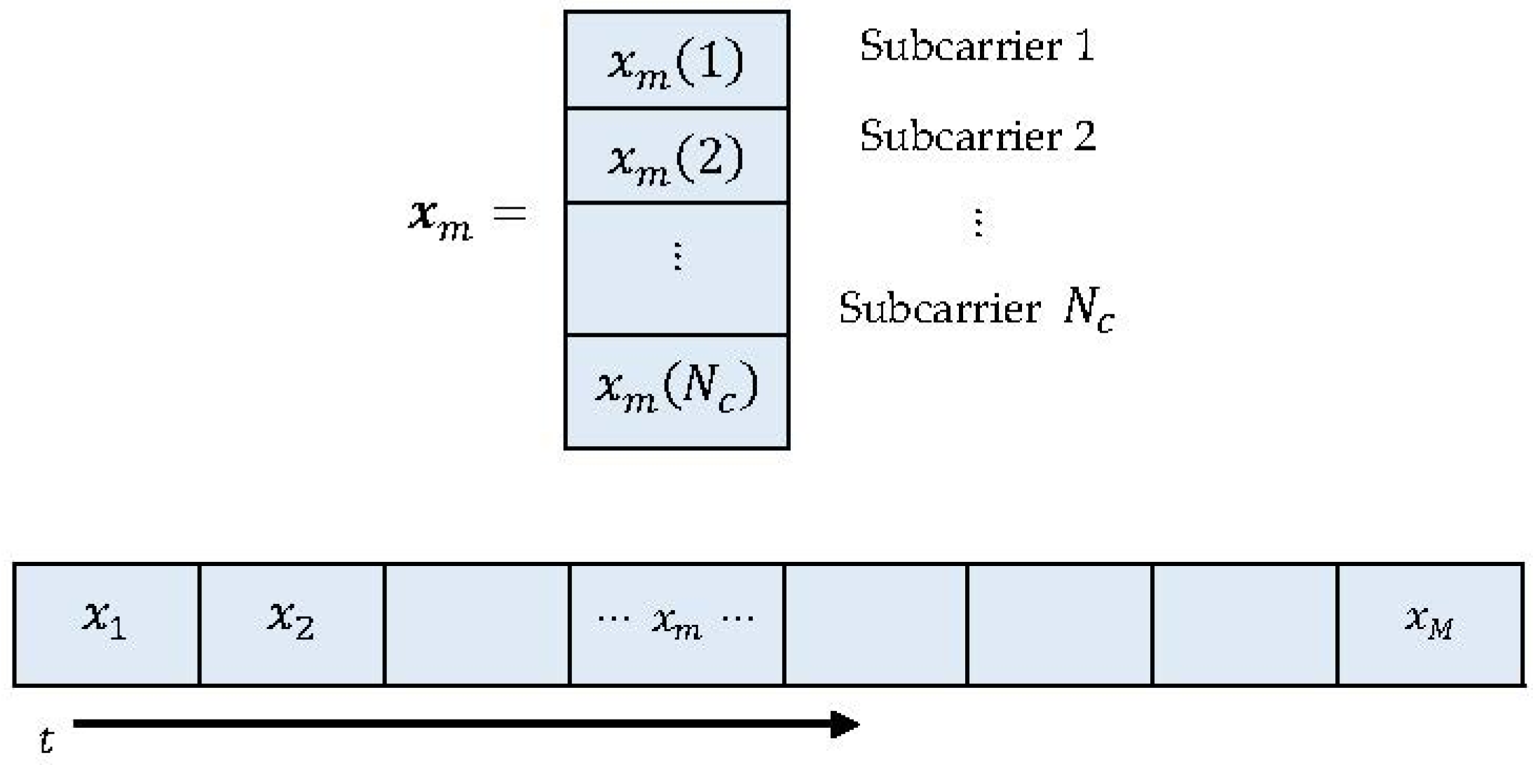
Assuming that the coherence time is long enough and the system uses a time-domain orthogonal training sequence, which is depicted in
Figure 2.
The data received by the user from the
th antenna is as follows:
where
is the received signal from all subcarriers from the
th antenna;
is the frequency domain response of all subcarrier channels of the
th antennas; the diagonal element of
is composed of
, and represents the pilot symbol on the
th subcarrier of the
th antenna; and
is a Gaussian noise with zero-mean and a variance of
.
The received signal of the simultaneous
antennas can be obtained as follows:
Substituting Equation (6) into Equation (9), we get the following:
4.1. Channel Estimation Based on Antenna Grouping and Block Sparsity
The goal is to estimate
based on
and then reconstruct the channel matrix
. Considering that
is a block sparse vector, to estimate
, the following optimization problem can be constructed [
12]:
As the 0-norm is non-convex discontinuous, under certain conditions, the 1-norm can be used instead of 0-norm, that is [
13,
16]:
Then, a convex optimization solution is performed on the Equation (12) to obtain a suitable solution. Similarly, Equation (11) can also be solved using low-complexity algorithms such as orthogonal matching pursuit (OMP) in a compressed sensing.
In fact, as mentioned earlier,
has a block sparse property, so if we take advantage of this, we can improve recovery performance and reduce computational complexity. An obvious feature of block sparseness is that for a certain zero block, its 2-norm must be zero, that is, if
, then
. Correspondingly, if a sub-block is not a zero block, its 2-norm must be greater than 0, that is, if
, then
. The authors in [
16] use the above properties to transform the original problem Equation (11) into the following optimization problem:
Equation (13) utilize the sum of the 2-norm of each sub-block as the objective function and makes better use of the characteristics of signal block sparseness so that better recovery performance can be obtained.
However, the entire estimation period starts from the transmission of the pilot signal by the first antenna of the BS to the end of the transmission of the pilot signal by the last antenna of the BS, so the time required for the user to perform downlink channel estimation is proportional to the number of antennas. If the number of antennas is large, a long estimation period is required, which may well exceed the channel coherence time, which means that when the estimation ends, the channel state has changed, and the channel estimation results are invalid [
7].
In order to solve the above problem, it is necessary to reduce the time taken to transmit the pilot sequence. Here, a packet transmission algorithm is proposed, which can effectively shorten the estimation counting cycle. Specifically, the antennas are equally divided into
groups, and each group includes
antennas. By having all the antennas in each group transmit the pilot sequence at the same time, the total transmission time will be reduced to the original
. In the case of packet transmission, the received signal
can be expressed as follows:
where the length of the received signal
is
;
represents the pilot matrix of the
th antenna in the
th group, which is a
dimensional matrix. Compared with the previous received signal
, the observed dimension is reduced, that is, the proposed algorithm is to reduce the transmission time by reducing the number of observations. The number of groups
should satisfy the following constraint:
Let
, so the following convex optimization can be reconstructed:
The above problem can be further transformed into a semi definite optimization problem (SDP) [
16]:
where
represents the semi-positive definite of the matrix. There are many ways to solve SDP problems in polynomial time. From the perspective of numerical calculation, solving SDP problem is more efficient [
16].
4.2. Low Complexity Channel Estimation Based on Block Matching Pursuit
The convex optimization method based on antenna grouping and block sparsity characteristics not only improves the accuracy of sparse position estimation, but also shortens the period of the entire downlink channel estimation. However, there are still some problems in solving Equation (17) directly. For example, the iterative process in the solution process cannot be controlled, and the computational complexity is high. In order to reduce the computational complexity based on the guaranteed performance, this section proposes an estimation algorithm based on block matching pursuit (BMP). The proposed algorithm can make each step in the estimation process clearer and more controllable.
Rewrite Equation (14) as follows:
If the index of the non-zero sub-block is known:
, and
, then Equation (18) can be expressed as follows:
If
and
, the Least Square(LS) estimation of
can be obtained as follows:
Equation (20) shows that if the index of the non-zero sub-blocks can be found, the estimation of the non-zero channel vector can be finally obtained by the LS algorithm. Therefore, the key to the problem is how to accurately find the index value of the non-zero sub-block.
Rewrite Equation (2) as follows:
Note that in the absence of noise, the value of the final result
should be a non-zero sub-block in
. It is concluded that if a block
corresponds to a sub-block
in
that is exactly a non-zero block, the correlation between
and
must be large. However, if a block
corresponds to a sub-block
in
that is exactly a zero sub-block, the correlation between
and
must be small. Based on the above interference, after obtaining the observed data
, the correlation between
and each sub-block in
can be determined as follows:
where
. To measure the correlation, take the 2-norm of the above results and let
After getting
, sort them by size, as follows:
If the true sparsity is known, then the first values in Equation (24) correspond to the sequence numbers as an estimate of the non-zero block position, and the LS estimation is performed according to Equation (20).
If the sparsity is unknown, an adaptive determination is required. Here is the following method: First, the pre-term difference operation of Equation (24) is performed to obtain the following:
Then, find the index corresponding to the maximum value in the results, that is, the estimation of the sparsity, namely
:
The steps of the block-based tracking (BMP) algorithm are shown in Algorithm 1.
| Algorithm 1. BMP |
Input: Received signal , perceptual matrix , All zero vector
Step 1: According to Equation (14), the received signal is correlated with each block of the matrix according to a previously known group situation: ,
Step 2: Sort the results of Step 1 in descending order:
Step 3: Perform a difference operation on the results obtained in Step 2:
Step 4: Find the index corresponding to the maximum value in the result of Step 3, which is the estimation of the sparsity:
Step 5: Determine the first indexes in Step 2: , find the matrix :
Step 6: Calculate the LS estimation of the sparse channel:
Step 7: According to the index: assigns each sub-block of obtained in Step 6 to :
. Where means taking the sub-block of
Step 8: The sub-blocks in that are not assigned continue to remain at 0
Output: Final estimated channel |
5. Simulation Results and Analysis
We used MATLAB R2017a simulator (R2017a, Mathworks, MA, USA) for experimentations.
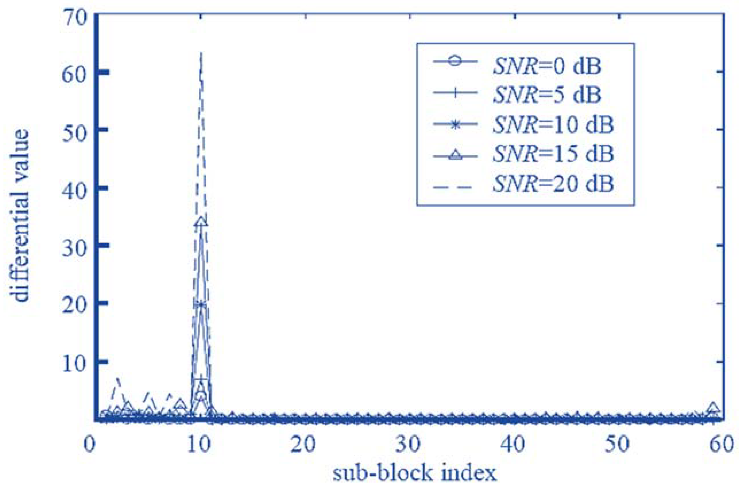
Table 1 shows the simulation parameters for the proposed system analysis. Equations (25) and (26) propose a method for judging the sparsity by calculating the difference of the correlation 2-norm.
Figure 3 shows the distribution of the difference calculated according to Equation (26) when
. As can be seen from
Figure 3, when
, although the noise interference is severe at this time, the maximum value obtained according to Equation (26) is small. However, it still appears at the position of true sparsity
, because according to Equation (23), the correlation between the submatrix corresponding to the non-zero sub-block and the received signal
should be greater than the correlation between the sub-matrix corresponding to the zero sub-block and
. Therefore, after performing the difference operation according to Equation (25), the maximum position found according to Equation (26) is a boundary position between the non-zero sub-block and the zero sub-block in a large probability, and the value is the sparsity. This shows that the proposed algorithm can still estimate the true sparseness at a low
SNR. It can also be seen from
Figure 3 that as the
SNR increases, the maximum value becomes larger and larger, and the accuracy of the estimation of the true sparsity is higher and higher. The simulation results show that the proposed algorithm can effectively estimate the channel sparsity.
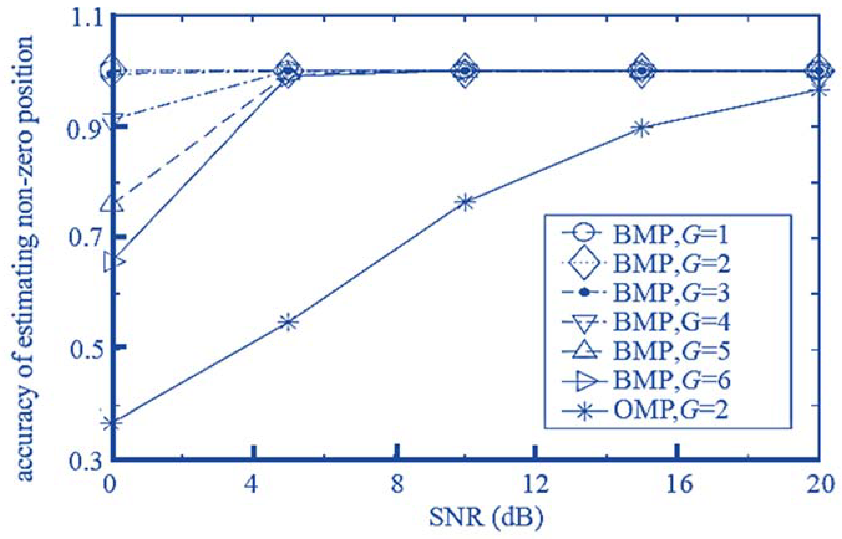
Figure 4 shows the correct rate of the proposed BMP scheme for non-zero position estimation. As can be seen from the
Figure 4, when
, even if the
SNR is very low, the proposed algorithm can also successfully estimate the location of non-zero sub-blocks. However, at low
SNR, as
increases, the probability of the algorithm correctly estimating the position of non-zero sub-blocks begins to decrease. For example, when
, the correct rate drops to approximately 90%. At
, the correct rate drops to approximately 75%. This is because as the
increases, the number of observations of the sparse signal
decreases, so the correct rate for non-zero position estimation decreases. However, when the
SNR exceeds 5 dB, the estimated correct rate exceeds 5 dB, the estimated correct rate in various grouping cases is close to 100%. The results show that the sparse recovery of the algorithm can be greatly improved by making full use of the block sparsity property and performing sparse recovery in units of sub-blocks. Compared with the classical OMP algorithm, the proposed BMP algorithm greatly improves the accuracy of estimating non-zero positions in the presence of noise. Even if the SNR rises to
, the OMP algorithm cannot reach 100%. This is because the traditional OMP algorithm does not utilize the feature of block sparseness, but separately judges each position. Therefore, if a certain position happens to be affected by relatively serious noise, it will lead to a judgement error. In contrast, because the proposed algorithm utilizes the block sparse property, the decision is performed in blocks. Even if individual locations in a block are seriously affected, the impact on the entire block can still be small. This will not affect the final decision on a non-zero position. The simulation results show that the proposed BMP algorithm has a significant improvement in anti-noise performance compared with the traditional OMP algorithm.
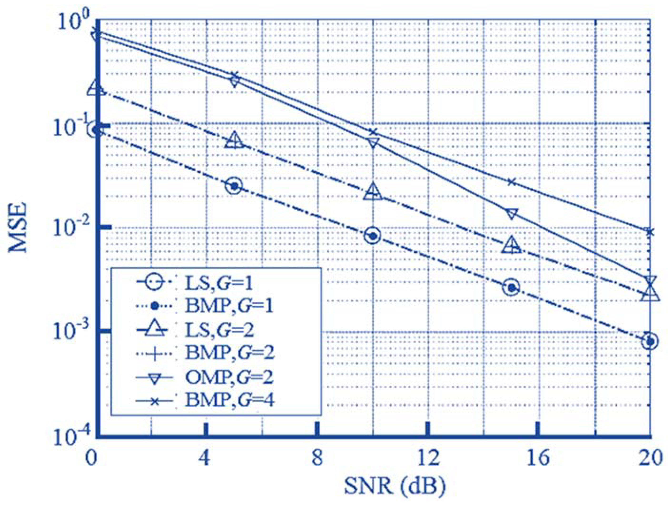
Figure 5 shows the MSE performance of the proposed BMP algorithm for different groupings. It also shows the performance of the traditional OMP algorithm and the LS algorithm for known non-zero sub-block positions for comparison. It can be seen from
Figure 5 that if the grouping is not performed, that is, each antenna transmits a pilot at the wrong time, the performance of the proposed BMP algorithm is exactly the same as that of the LS algorithm. This is because, in the case where the antenna is not grouped, even if the
SNR is low, the proposed algorithm can accurately estimate the position of the non-zero sub-block (as shown in
Figure 4), so it is equivalent to the performance of the LS algorithm. When the antennas are grouped, because the number of observations of the sparse signal
decreases correspondingly with the increase of
, the recovery performance of the sparse signal is degraded. However, it is noted that the increase of
shortens the time required for downlink channel estimation, improves the spectral efficiency, and effectively avoids the problem that the estimation time is too long. Therefore, in practice, the appropriate
should be selected according to the system parameters and requirements.
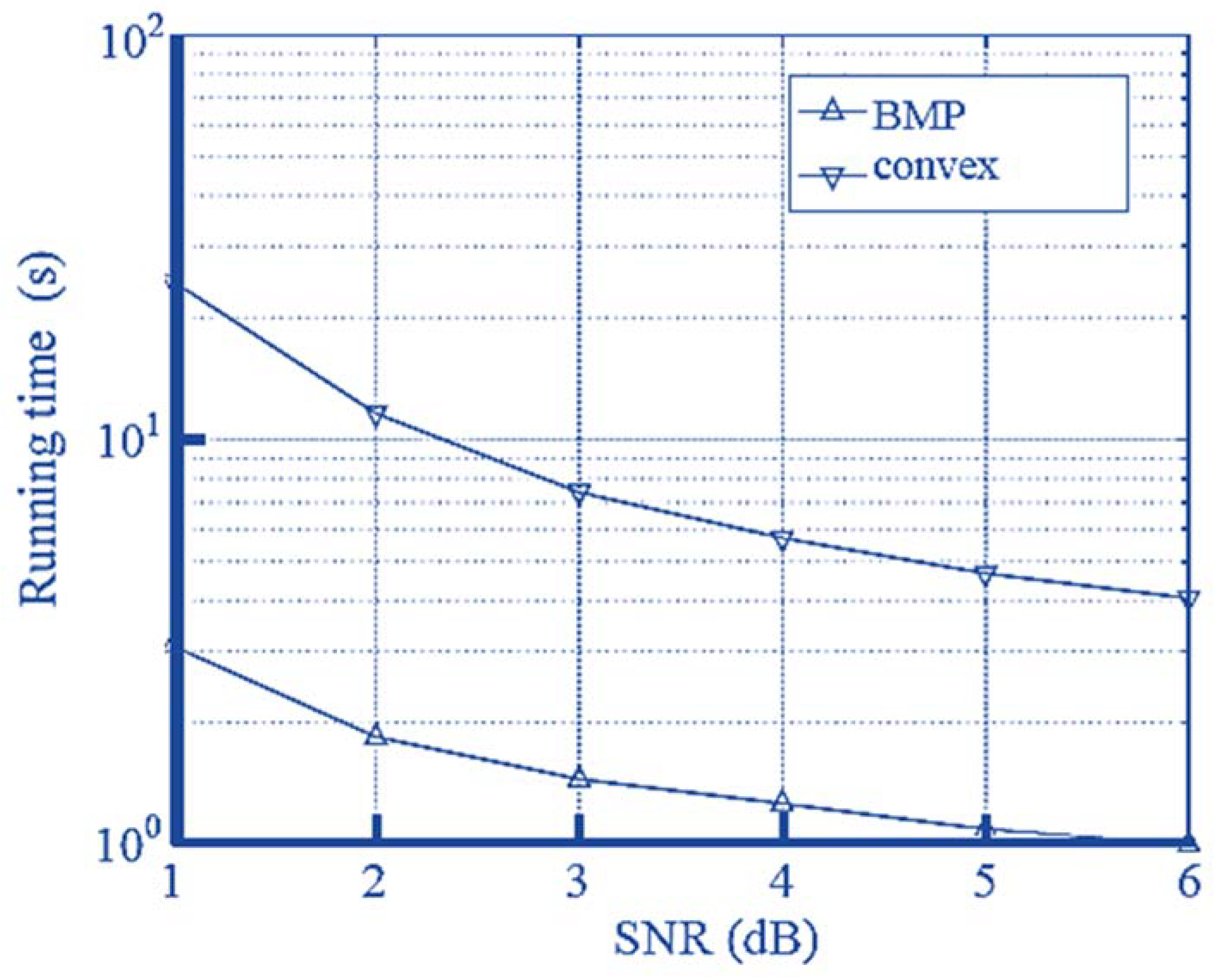
Figure 6 compares the proposed BMP algorithm with the proposed grouping method and the direct optimization method to solve the running time required by Equation (17) (corresponding to the “block convex optimization method” in the figure). As can be seen from
Figure 6, the proposed BMP algorithm takes less time in any grouping situation, that is, its computational complexity is always lower than that of the convex optimization algorithm.
This is because the convex optimization algorithm contains high-dimensional matrix operations in every iteration, so the computational complexity is relatively large, and the convex optimization algorithm needs to further analyze the results to obtain non-zero sub-blocks after obtaining the convex optimization operation results. Further analysis of the results is required to find the location of the non-zero sub-blocks and zero sub-blocks. In contrast, the proposed BMP algorithm first finds the non-zero sub-block position and then directly performs the LS solution of the dimensionality reduction, so the complexity is low.
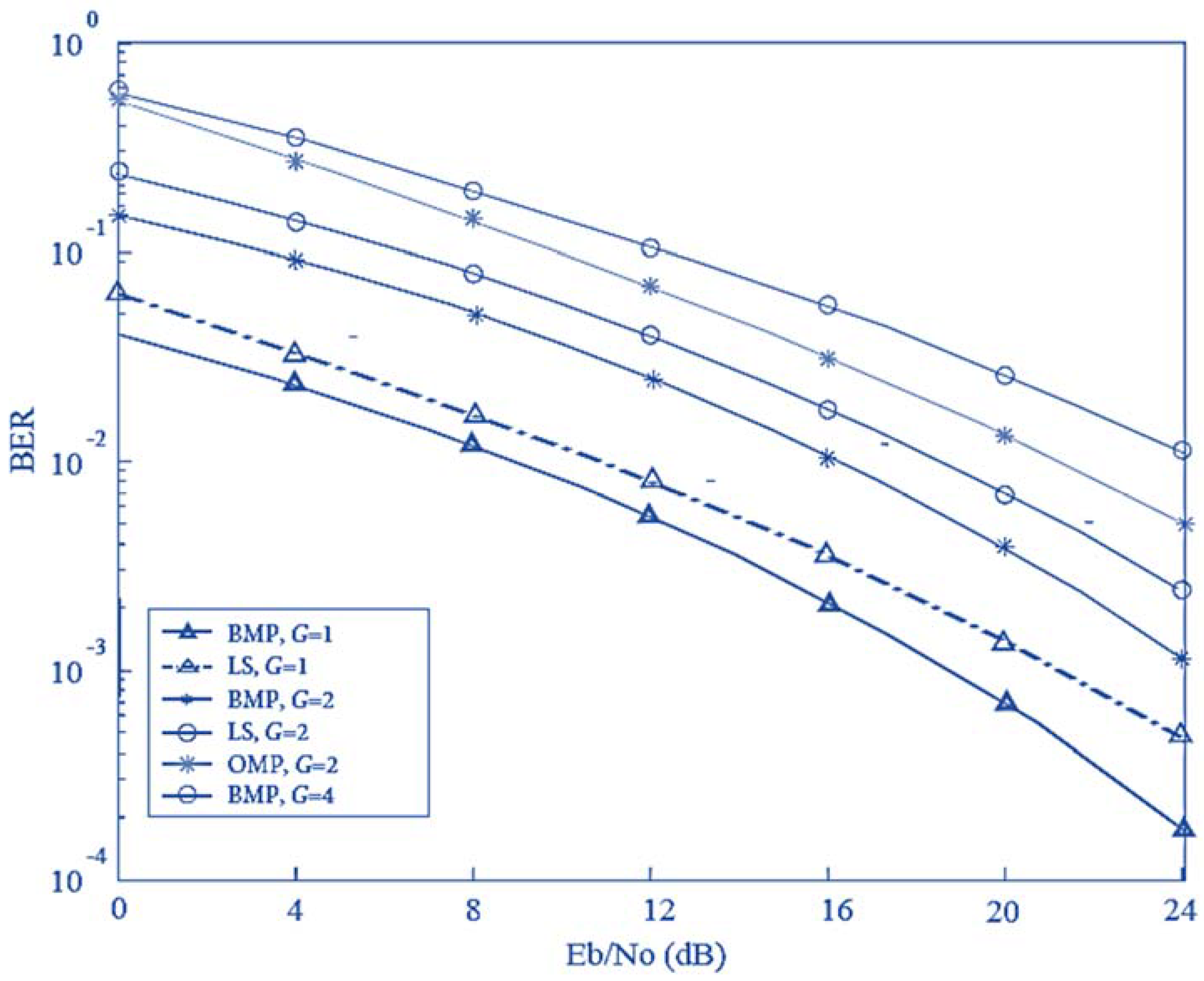
Figure 7 compares the Bit Error Rate (BER) as a function of
Eb/
N0 for the proposed BMP algorithm and the existing LS and OMP algorithm for different groupings. It can be seen from
Figure 7 that if the grouping is not performed, that is, each antenna transmits a pilot at the wrong time, the performance of the proposed BMP algorithm is better than that of the LS algorithm. This is because, in the case where the antenna is not grouped, even if the
Eb/
N0 is low, the proposed algorithm can accurately estimate the position of the non-zero sub-block (as shown in
Figure 4), so its performance is better than the performance of the LS algorithm. Moreover, the BER performance for
G = 2 of the proposed BMP is better than LS at
G = 2, but worse than LS at
G = 1. Also, for
G = 4, the BMP performance degrades and is worse than that of the OMP at
G = 2. Therefore, such results indicate that proper grouping affects the system performance, which must be considered.
6. Conclusions
In this paper, a low-complexity block matching pursuit (BMP) algorithm based on antenna grouping and block sparsity is proposed for FDD massive MIMO-OFDM systems. As the proposed algorithm makes full use of the block sparse property, the signal is recovered according to the sub-block, thereby enhancing the anti-noise performance of the algorithm and improving the operation efficiency. The simulation results show that the proposed algorithm is superior to the traditional OMP algorithm in determining channel sparsity and non-zero sub-block position, and reconstructing the sparse channel vector. The proposed BMP algorithm is significantly lower in computational complexity than the convex optimization algorithm, which is a good solution for the user with poor computing power. In addition, the proposed algorithm shortens the training time required for channel estimation by grouping the transmit antennas, thereby effectively avoiding estimation. Therefore, the problem caused by the estimation period exceeding the channel coherence time and the channel estimation result is invalid and can be effectively avoided.
In future work, we will consider the integration of millimeter wave technology with massive MIMO using the BMP algorithm and analyze the channel characteristics. Moreover, other important system parameters such as number of feedback bits, hardware impairments, Signal-to-interference and noise ratio (SINR), and energy efficiency will be analyzed.


