Article

Establishment of an Inventory for the Life Cycle Cost (LCC) Analysis of a Water Supply System

1
Environment and Plant Engineering Research Institute, Korea Institute of Civil Engineering and Building Technology, Daehwa-dong 315, Goyangdae-Ro, Ilsanseo-gu, Goyang-si, Gyeonggi-do 10223, Korea
2
Smart City Construction Engineering, University of Science & Technology (UST), 217, Gajeong-ro, Yuseong-gu, Daejeon 34113, Korea
3
Water Supply & Sewerage Department 2, SAMAN Corporation, Gwangnaru-ro 56-gil 85, Gwangjin-gu, Seoul 05116, Korea
*
Authors to whom correspondence should be addressed.
Water 2017, 9(8), 592; https://doi.org/10.3390/w9080592
Submission received: 7 March 2017 / Revised: 31 July 2017 / Accepted: 1 August 2017 / Published: 15 August 2017
(This article belongs to the Special Issue Water Networks Management: New Perspectives)

Abstract

:
This paper aimed to develop an inventory that is necessary for the life cycle cost (LCC) analysis of a water supply system. Based on an established inventory system, data items for each asset category were defined. The water supply system was divided into pipelines, pumps and distribution facilities. Pipeline facilities that account for the majority of water supply systems were grouped, according to the purposes and functions of pipes, into conveyance facilities, transmission facilities, distribution facilities and supply facilities. The inventory of water supply systems were divided into five levels, and the higher the level, the more detailed facilities were classified. Basically, 12 items and diagnosis results were included in the system to distinguish the characteristics of each asset, and it was ensured that administrators could add or change items later if necessary. The data used in this study were established based on real data from the Yeong-Wol (YW) pipeline systems.

1. Introduction

The purpose of water supply systems is to provide water to consumers in a stable way while satisfying both the demand of consumers and the goals of the supplier. To accomplish this purpose, it is necessary to operate and maintain water supply facilities in a systematic way. A water supply facility is a type of infrastructure that owns and operates a range of equipment and buildings, and in order to operate these, ongoing maintenance by a facility manager is required [1].
About 161 regional waterworks operators (special metropolitan cities (7), special self-governing cities (1), special self-governing provinces (1), cities (75), guns (77)) and multi-regional waterworks operators (1))) covered 98.6% of the total population (approximately 51,712,000 persons) as of the end of December 2014 [2] in South Korea
The life cycle cost (LCC) is the cost of an asset, or its parts throughout its life cycle, while fulfilling the performance requirements. (BS ISO 15686-5, 3.1.1.7).
LCC may be used during following four stages of the life cycle of any constructed asset:
(a)
Project investment and planning; Whole life costing/ Life cycle cost (WLC/LCC) strategic option analyses; preconstruction;
(b)
Design and construction; LCC during construction, at scheme, functional, system and detailed component levels;
(c)
During occupation; LCC during occupation (cost-in-use); post-construction; and
(d)
Disposal; LCC at end-of-life/end-of-interest. (BS ISO 15686-5:2008).
According to a literature review of life cycle costing and life cycle assessment, there are four important steps in life cycle costing:
  • The first step is to generate cost profiles corresponding to each considered option. Each cost profile is a series of planning, construction, maintenance, support, use, and disposal cost estimates calculated over the intended service life of the corresponding facility option.
  • Next, each cost profile is translated to an equivalence measure to support a common and credible basis of comparison among the considered options.
  • Third, the results of the time value of the money computations are used to rank the options according to life cycle cost.
  • Finally, the results of the LCC procedure are passed on to the infrastructure owner to support rational decision making.
Life cycle assessment (LCA) is a technique for assessing potential environmental aspects and potential aspects associated with a product (or service), by:
  • Compiling an inventory of relevant inputs and outputs;
  • Evaluating the potential environmental impacts associated with those inputs and outputs; and
  • Interpreting the results of the inventory and impact phases in relation to the objectives of the study. (ISO 14040.2 Draft: Life Cycle Assessment—Principles and Guidelines)
According to ISO 14040, LCA is divided into four phases:
  • Goal and scope definition;
  • Inventory analysis;
  • Impact assessment; and
  • Interpretation.
Life cycle assessment (LCA) is necessary for defining the best environmental management strategies. Anna [3] studied the environmental impacts of a sewer system and determined the most environmentally friendly design strategy for small to medium sized cities by composing an inventory of the materials and energy. Establishing an inventory is the basic step for LCA or LCC analysis. Sanjuan [4] statistically analyzed 50 cities to find the relations between different variables regarding water consumption linked with the environmental impact of a network.
Social life cost assessment (SLCA) is defined as the methodology for the assessment of positive and negative social impacts that are generated by a product/service in its life cycle and in relation to the different groups of stakeholders involved, with the aim of promoting the improvement of a product’s socio-economic performance throughout its life cycle [5].
Studies of the introduction of maintenance and management systems with the life cycle cost (LCC) analysis technique applied have been continuously conducted in an effort to efficiently utilize the limited amount of budget and prevent costs for maintenance and management from rapidly rising. One of the important things about the maintenance of a water supply network is calculating the optimum time for the replacement of water supply pipes. For that purpose technical–economic analyses have been used to take into account all kinds of costs for the repair or replacement of trouble-causing parts of a network [6]. Yoon [7] reviewed and compared the advantages of four different design cases, presenting the optimal techniques and tasks that should be carried out in order to maximize the economic utility of a project through LCC analysis. Applying the LCC method, Lee [8] compared the LCCs of modern hanok housing and apartment housing in order to provide basic information for the choice of housing A series of systems which are carried out to satisfy the minimum life cycle cost of a water supply system and to reach the desired level of service are defined as asset management [9]. Previously, life cycle assessment research in the area of water cycle management has mainly discussed specific aspects of wastewater systems, i.e., quantifying the environmental load of wastewater systems [10,11,12,13,14] or biosolid systems [15,16]. Life cycle assessment has also been used for the definition of environmental sustainability indicators for wastewater systems [17,18] and more recently for urban water systems [19]. Son [20] analyzed the economic valuation of sewage disposal facilities and suggested, based on the results of the LCC analysis, that it would be more economically feasible to directly operate such facilities for the first four to five years and then switch to a consignment operating system.
Heo [21], in his study, selected a strategic simulation for the repair, rehabilitation and improved performance of existing dam structures using LCC analysis techniques. Life cycle assessments consist of three main steps and a generally acknowledged fourth step: (1) goal definition and scoping (generally included); (2) inventory analysis; (3) impact analysis; and (4) improvement analysis [22,23].
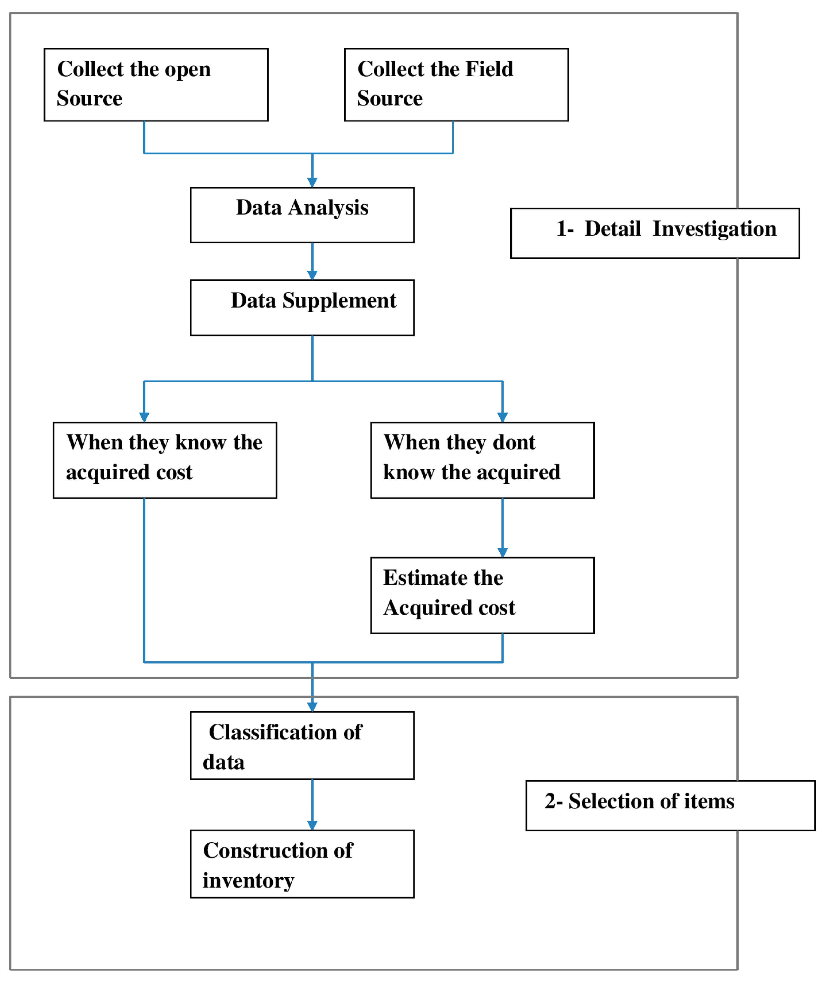
The work that is pre-required to analyze an LCC is the classification of the asset according to the classification systems of water supply systems. Any facility must be arranged to determine the current status of the management. To analyze the LCC of water supply systems, it is necessary to grasp the current status of assets and classify the assets of the water supply system in advance. That is, the management of any facility should be preceded by the understanding of the current conditions.
This paper focuses on the classification of an inventory of a water supply system that is the basis of an LCC analysis of the water supply system. This classification makes inventory establishment for LCC analysis easy because, in a water supply system, there are many machines and items involved, and with the help of this classification each and every item can be identified in more depth. It also tells the waterworks manager when, where and which item needs to be repaired, rehabilitated and replaced.

Methodology of the Classification System of a Water Supply System

Water supply systems are classified into three levels, and the types are classified at the first level (category), and sub-facilities under each category item are classified at the second level (subcategory). The composition of each sub-facility is defined at the third level (sub-sub category).
The types of water supply system are classified at the level of “category”, and target water supply systems are divided into six categories including water intake facilities, water conveyance facilities, water treatment facilities, water transmission facilities, water distribution facilities and water supply facilities.
The sub-facilities of each category are classified at the level of “subcategory”, and they are distinguished by function and use, or structure and form.
At the level of sub-sub category, civil engineering structures, facilities and equipment that compose each type of sub-facility are classified according to sub-sub category items by function or structure or form. They are, in turn, divided in detail into pipe, pump, valve, water gate, tank, machine, special, measurement, and others as shown in the following table. Table 1 shows the sub-sub category items and their descriptions.

2. Materials and Methods

2.1. Procedure of the Construction of the Asset Inventory

To establish an asset inventory, target assets should be surveyed in detail first. Asset surveys can be divided into open source surveys and field surveys. Collected information is analyzed, and, if necessary, additional surveys are conducted to supplement it. When information on acquisition costs are available, they can be directly used. If not, acquisition costs should be estimated based on relevant factors.
The next step is to select items, classify them by level, and establish the inventory of assets by level. The classified inventory is later used for LCC analysis. The flow chart for establishing an asset inventory is shown in Figure 1.
Water supply systems are largely divided, according to the functions of the facilities, into water intake facilities, water conveyance facilities, water treatment facilities, water transmission facilities, water supply facilities and water distribution facilities [24]. The scope of objective facilities is defined to include general civil engineering structures of each water supply system, pipe, pump, valve, machinery, MEP (mechanical, electrical, plumbing) facilities such as electronic and instrumentation/control devices, and other accessory equipment.

2.2. Establishment of the Inventory of the Water Supply System

2.2.1. Investigation of Test Bed (TB)

Test bed is the name of the particular area from which data was provided and the application was performed. It is the common name of a test area.
YWYeong-Wol
YHYeong-Heung
DPDeog-Po
JRJang-Leung
PGPal-Goe
SNSouth and North
The water supply system of the TB section with the YW pipeline systems constructed is shown in Figure 2, and its main facilities are as follows:
-
YW water intake facility: 13,500 m3/day
-
YW water treatment facility: 13,500 m3/day, rapid filtration method
-
Pump stations (four sites): YH, DP, PG, JR
-
Distribution facilities (five sites): YW, YH, DP, PG & SN
Figure 3 shows the water treatment chart of the YW pipeline system. The layout plans of the YW water intake facility and the YW water treatment facility are as shown below, and the location of the main facilities are also illustrated in Figure 4.

2.2.2. Subjects and Division of Water Supply System

The water supply systems in this research were divided into water supply pipelines (including pipeline structures), pump stations, and distribution facilities as shown in Table 2.
The assets of water supply systems can be divided into pipelines and valves that account for the majority of pipeline networks, pump stations, and distribution facilities.
Pipeline facilities that account for the majority of water supply systems can be grouped according to the purposes and functions of the pipes, into the intake and conveyance pipes, transmission pipes, distribution pipes, supply pipes, and fire protection pipes. Valves with various functions are installed throughout water supply systems. Pump station facilities include a pump station building, underground Reinforced Concrete (RC) box structures, booster pumps and control panels, and supply water to target regions. Distribution reservoir facilities include valves, control panels and water level gauges, and supply water to houses.

2.3. Classification According to Pipe Type

Based on the information on pipe types acquired from the YW pipeline systems, the main pipe types used in individual facilities were identified, and information on their diameters was collected.

2.3.1. Water Conveyance Facility

There were various kind of pipes such as Cast iron pipe (CIP), Ductile cast iron pipe (DCIP), Polycarbonate (PC) and Polyethylene (PE), and especially DCIP accounted for 59% of the pipes used in the facilities. Pipes of different diameters were used, and those ranging from 150 mm to 600 mm took up 53% of the pipes used in the facilities as shown in Figure 5.

2.3.2. Water Transmission Facility

DCIP and Steel Pipe (SP) were mainly used in the water transmission facilities, and especially DCIP accounted for 71% of the pipes used in the facilities. Pipes of different diameters were used, and those ranging from 100 mm to 400 mm took up 80% of the pipes used in the facilities as shown in Figure 6.

2.3.3. Water Distribution Facility

There were various kind of pipes such as CIP, DCIP, High impact PVC pipe, 3 layers (HI-3P), Polyethylene (PE), Polyethylene power fused pipe (PFP), Steel Pipe (SP) and High Impact PVC pipe (HI-VP), and especially DCIP accounted for 71% of the pipes used in the facilities. Pipes of different diameters were used, and those ranging from 50 mm to 500 mm, and 100 mm took up 32% of the pipes used in the facilities as shown in Figure 7.

2.3.4. Water Supply Facility

There were various kinds of pipes such as, Galvanized steel pipe (GSP), High density polythylene (HDPE), PFP, Stainless steel (STS), HI-VP and Pre-Insulated pipe (PIP), and especially PFP accounted for 74% of the pipes used in the facilities. Pipes of different diameters were used, and those ranging from 13 mm to 50 mm, and 50 mm took up 36% of the pipes used in the facilities as shown in Figure 8.

3. Results and Discussion

Based on the theoretical review, the standards of water supply systems were systematically revised and supplemented. The developed program was set to ensure administrators can modify levels or content.
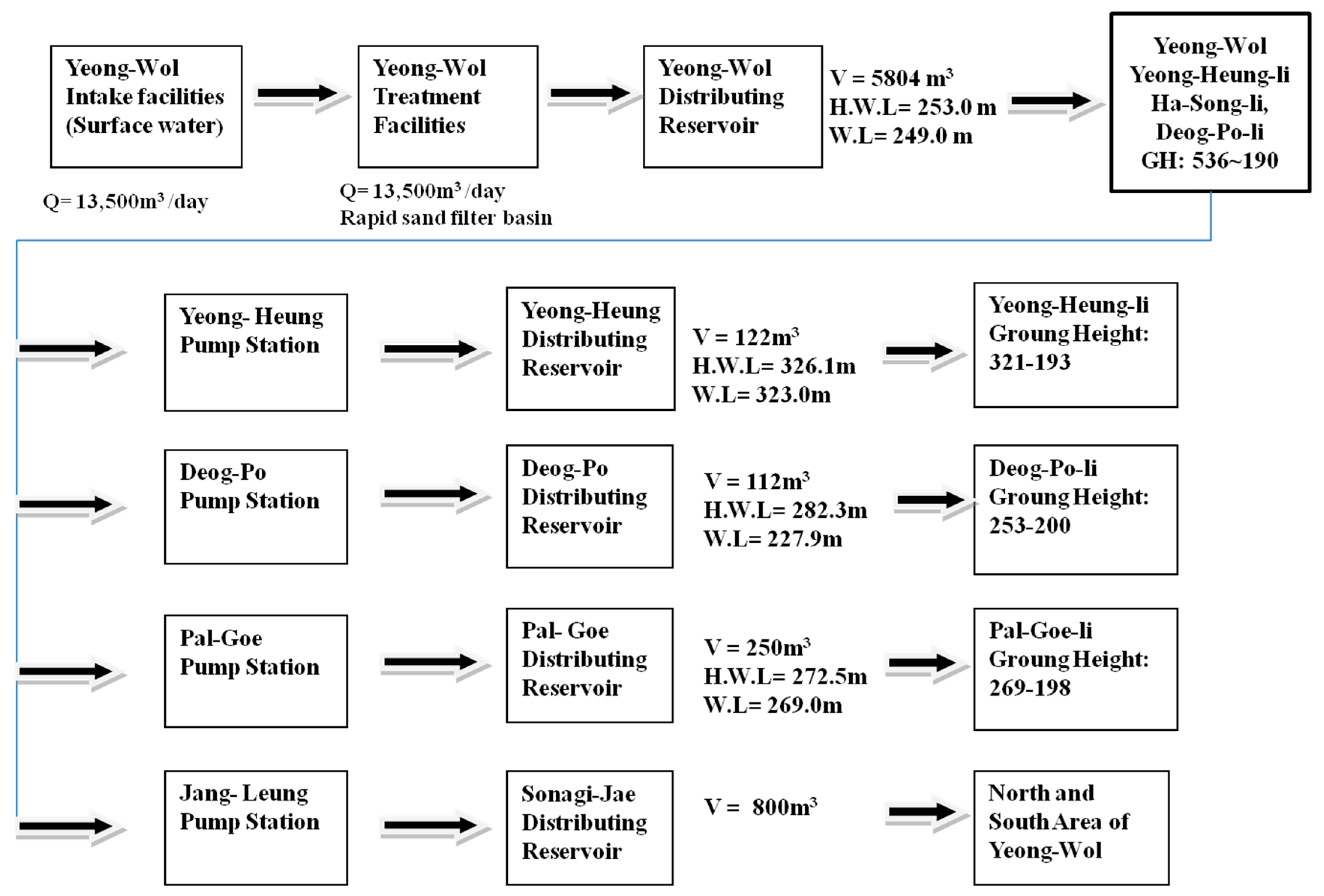
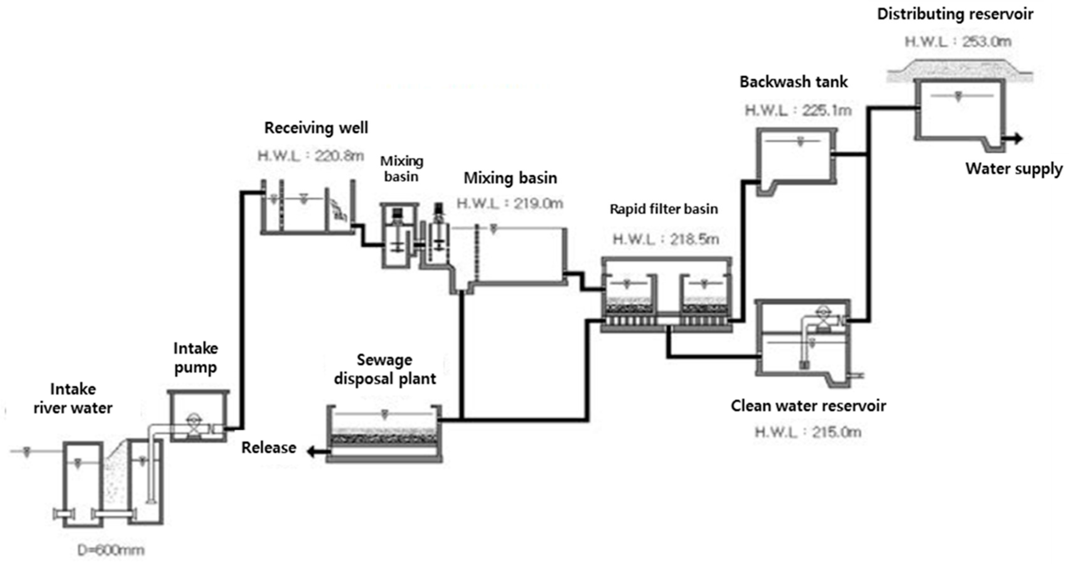
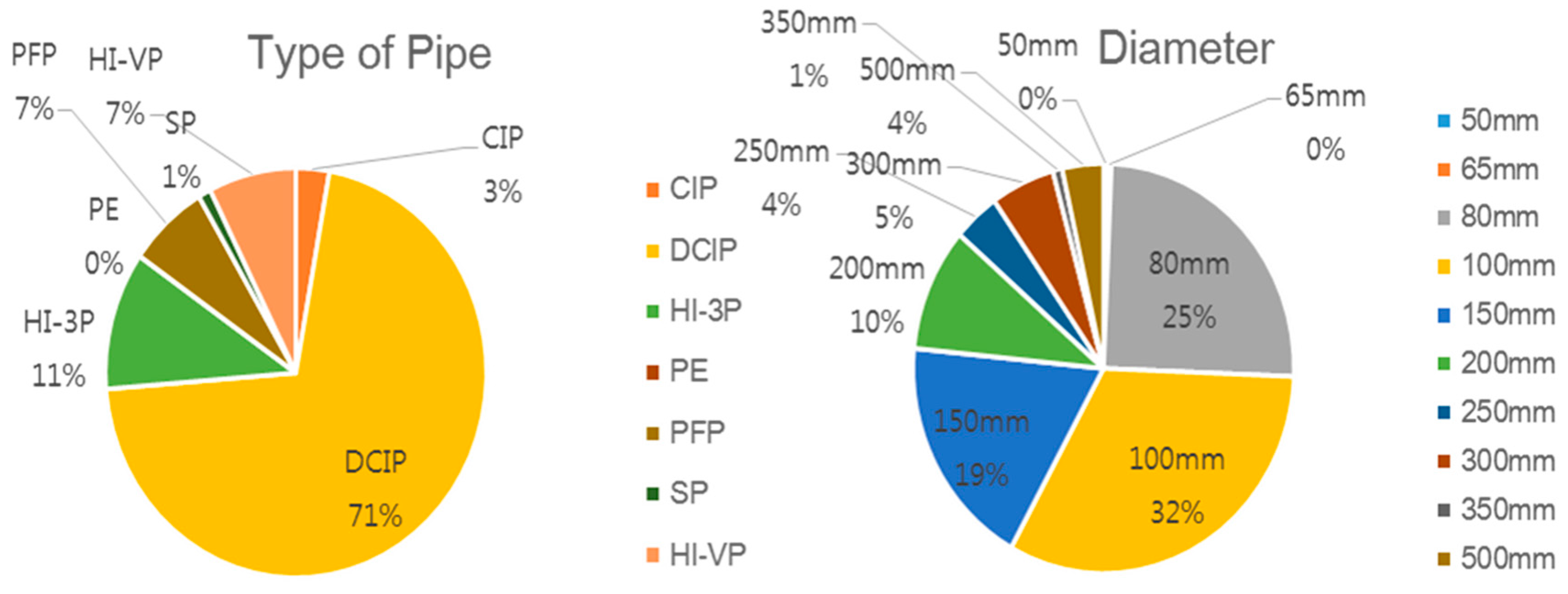
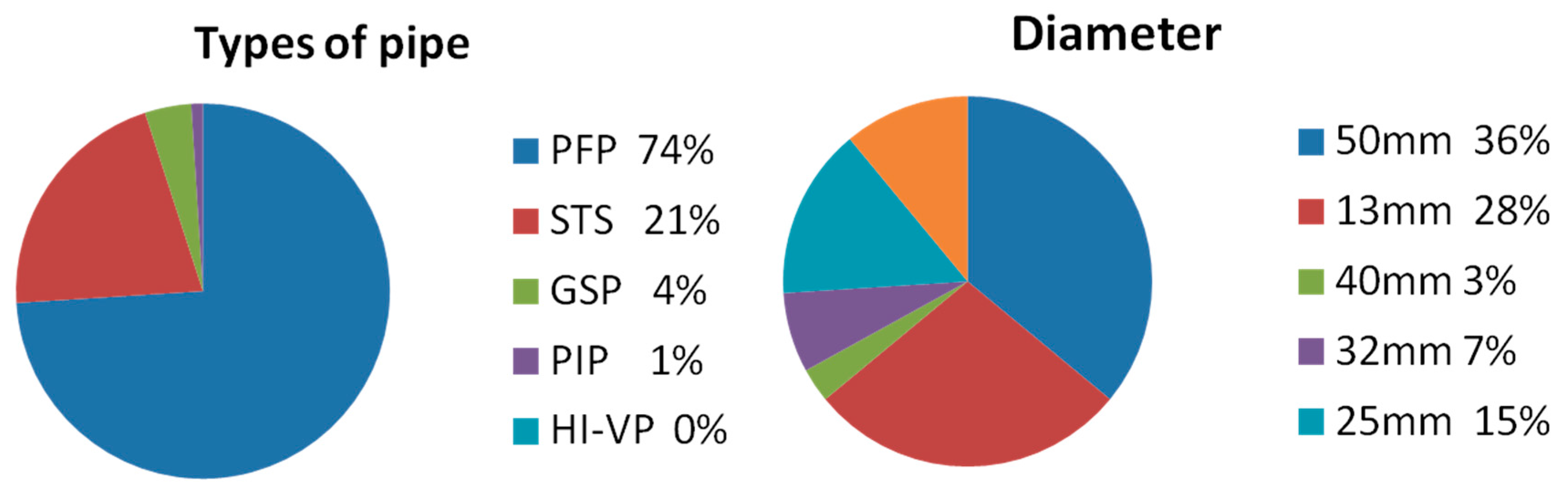
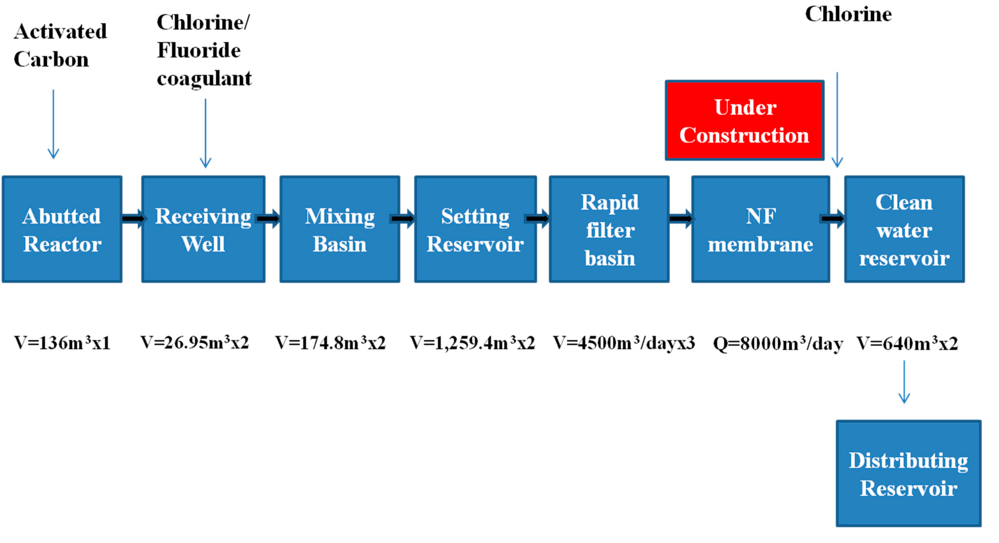
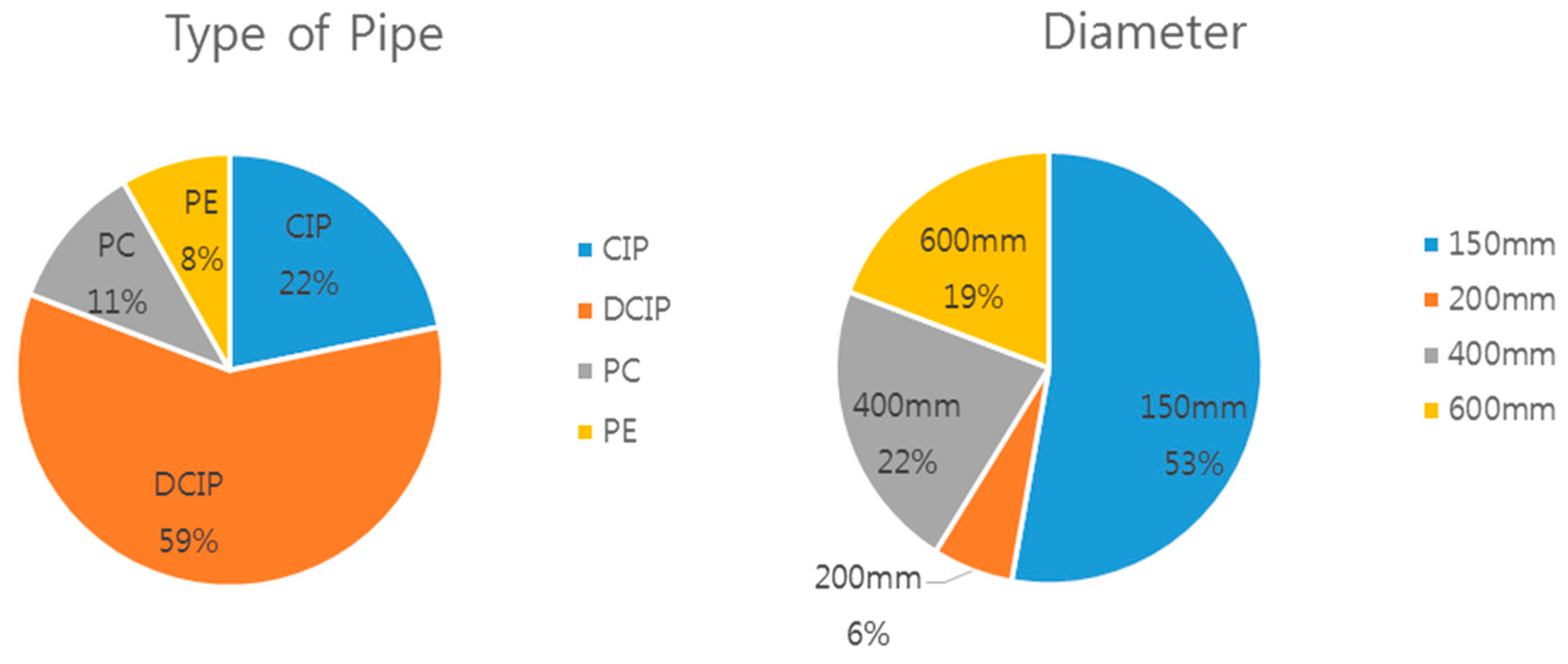
In analyzing the water supply systems in this study, water treatment facilities were excluded to focus on pipelines. The data used in this study were established based on real data from the YW pipeline systems.
Inventories of water supply systems were divided into five levels, and the higher the level, the more detailed facilities are classified. The Table 3, Table 4, Table 5, Table 6 and Table 7 show the classification of facilities from Level 1 to Level 5.
The tables above indicate that the classification scheme has a hierarchical structure. All the detailed contents above are just listed by level, not in order of any importance.
The paper divided the water supply system broadly into five different levels for the establishment of an inventory, that is, the basic step for LCC analysis. The above table indicates that the classification scheme has a hierarchical structure. The hierarchical structure is shown in 
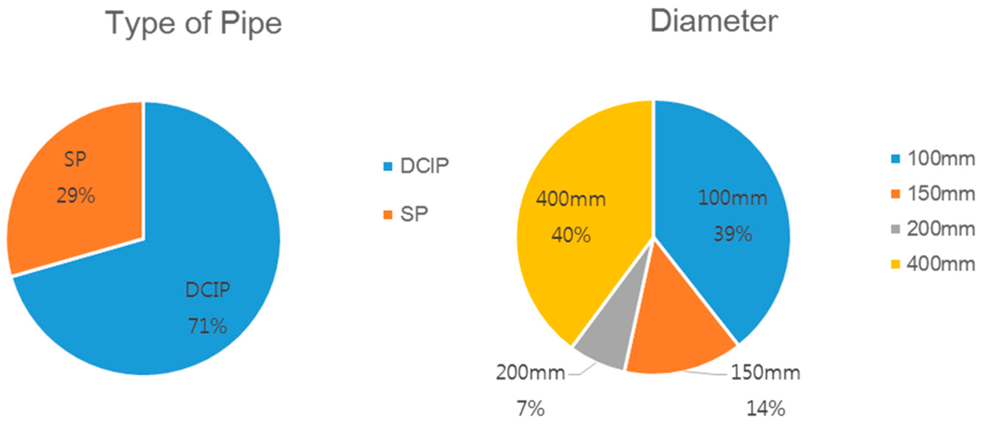
Supplementary Materials. In the previous literature there is no such kind of classification. Water supply systems were divided into five levels, and the higher the level, the more detailed facilities were classified. The preceding tables show the classification of facilities from Level 1 to Level 5. In conclusion, water supply systems were divided into five levels, and to analyze each facility, data from the YW pipeline system were utilized. In Levels 4 and 5, the types and diameters of pipes were identified to easily distinguish their different characteristics. The following table shows an example of the establishment of an inventory.

Generalization of Inventory Composition

The establishment of an inventory of water supply systems was prioritized first in this study, but it was also important to select inventory items. There were certain necessary items that should exist in an inventory program when LCC is analyzed or data are accumulated.
Based on the data acquired from fields, the necessary items for LCC analysis were established in consultation with experts in water supply systems as shown in Table 8 and Table 9.
Also, diagnosis result should be contained in the inventory items. To prevent any loss of data or items caused by the careless operation of some users, only administrators are allowed to change, add or delete inventory items.

4. Conclusions

The procedure was defined to develop an inventory for the water supply system, which is the basic step for LCC analysis of a water supply system comprised of many items and machines. This paper developed an inventory that in-depth classified each item of a water supply system. To increase the management efficiency of a water supply system, inventory items were systematically classified using a tree shaped structure that also helps the waterworks manager to know when and which item need to be replaced, repaired or rehabilitated. The water supply system was divided into pipelines, pump stations and distribution facilities. According to their use and function, pipes are also classified into different facilities. Based on the field data acquired from the Yeong-wol (YW) pipeline systems, an inventory structure with five levels was developed The higher the level, the more detailed facilities were classified. In this study, water treatment facilities were excluded to focus on the water supply system. In particular, the types and diameters of pipes were identified by level for convenient data management, and 12 items required for the inventory were suggested.

Supplementary Materials

The following are available online at www.mdpi.com/2073-4441/9/8/592/s1. Figure S1. Hierarchical structure of water conveyance facility. Figure S2. Hierarchical structure of water transmission facility. Figure S3. Hierarchical structure of water distribution facility. Figure S4. Hierarchical structure of water supply facility.

Acknowledgements

This work was supported by Guideline of non-destructive precision inspection and system improvement plan.

Author Contributions

The idea of inventory establishment for water supply system was given by Hongcheol Shin, which was redefined and executed by Hyundong Lee. The Data of YW pipeline system was collected by Myeongsik Kong, and it was analyzed and written in paper form by Usman Rasheed.

Conflicts of Interest

The authors declare no conflicts of interest.

References

  1. Du, F.; Woods, G.J.; Kang, D.; Lansey, K.E.; Arnold, R.G. Life Cycle Analysis for Water and Wastewater Pipe Materials. J. Environ. Eng. 2013, 139, 703–711. [Google Scholar] [CrossRef]
  2. Ministry of Environment. Statistics of Waterworks 2014; Ministry of Environment: Sejong City, Korea, 2015.
  3. Petit, A.; Sanjuan, D.; Gasol, C.M.; Villalba, G.; Suárez-Ojeda, M.E.; Gabarrell, X.; Josa, A.; Rieradevall, J. Environmental Assessment of Sewer Construction in Small to Medium Sized Cities Using Life Cycle Assessment. Water Resour. Manag. 2014, 28, 979–997. [Google Scholar] [CrossRef]
  4. Sanjuan-Delmás, D.; Petit-Boix, A.; Gasol, C.M.; Villalba, G.; Suárez-Ojeda, M.E.; Gabarrell, X.; Josa, A.; Rieradevall, J. Environmental assessment of different pipelines for drinking water transport and distribution network in small to medium cities: A case from Betanzos, Spain. J. Clean. Prod. 2014, 66, 588–598. [Google Scholar] [CrossRef]
  5. Petti, L.; Campanella, P. The Social LCA: The State of Art of an Evolving Methodology. In The Annals of the “Stefan Cel Mare” University of Suceava; Fascicle of the Faculty of Economics and1-Public Administration: Suceava, Romania, 2010; Volume 9, pp. 47–54. [Google Scholar]
  6. Kanakoudis, V. A trouble shooting manual for handling operational problems in water pipe networks. J. Water Supply Res. Technol. AQUA 2004, 53, 109–124. [Google Scholar]
  7. Yoon, G.L.; Kang, O.R.; Kim, D.H. Practices in VE/LCC based Design of Harbor Structures. J. Korean Soc. Coast. Ocean Eng. 2008, 20, 390–400. [Google Scholar]
  8. Lee, H.W. Compare and Analysis on Economic Feasibility of Modern Hanok Housing and Common Residence (Apartment) Applying LCC Method. Master’s Thesis, Seoul National University of Science and Technology, Seoul, Korea, 2013. [Google Scholar]
  9. Kim, W.J.; Jung, J.H.; Han, S.J.; Jung, H.C.; Kim, Y.H.; Inn, Y.S.; Ko, M.S. Development of Water and Wastewater Pipeline Total Asset Management System; Project, Report; KICT: Goyang, Gyeonggi-do, Korea; Hwaincem Tech: Gyeonggi-do, Korea, 2009. [Google Scholar]
  10. Lundin, M.; Bengtsson, M.; Molander, S. Life Cycle Assessment of Wastewater Systems: Influence of System Boundaries and Scale on Calculated Environmental Loads. Environ. Sci. Technol. 2000, 34, 180–186. [Google Scholar] [CrossRef]
  11. Bengtsson, M.; Lundin, M.; Molander, S. Life Cycle Assessment of Wastewater Systems: Case Studies of Conventional Treatment, Urine Sorting and Liquid Composting in Three Swedish Municipalities; Technical Environmental Planning, Report; Chalmers University of Technology: Gothenburg, Sweden, 1997; Volume 9, pp. 2–11. ISSN 1400-95600. [Google Scholar]
  12. Pisal, M.B.; Quazi, T.Z. Zero water discharge for sustainable development—An investigation of process industry-1. Int. J. Mech. Prod. Eng. 2014, 2, 80–81. [Google Scholar]
  13. Tillman, A.; Svingby, M.; Lundstrom, H. Life Cycle Assessment of Municipal Waste Water Systems. Int. J. LCA 1998, 3, 145–157. [Google Scholar] [CrossRef]
  14. Beavis, P.; Lundie, S. Integrated environmental assessment of tertiary and residuals treatment LCA in the wastewater industry. Water Sci. Technol. 2003, 47, 109–116. [Google Scholar] [PubMed]
  15. Peters, G.M.; Lundie, S. Life-cycle assessment of biosolids processing options. J. Ind. Ecol. 2001, 5, 103–121. [Google Scholar] [CrossRef]
  16. Dennison, F.J.; Azapagic, A.; Clift, R.; Colbourne, J.S. Assessing management options for wastewater treatment works in the context of life cycle assessment. Water Sci. Technol. 1998, 38, 23–30. [Google Scholar]
  17. Roeleveld, P.J.; Klapwijk, A.; Eggels, P.G.; Rulkens, W.H.; van Starkenburg, W. Sustainability of municipal wastewater treatment. Water Sci. Technol. 1997, 10, 221–228. [Google Scholar]
  18. Lundin, M.; Molander, S.; Morrison, G.M. A set of indicators for the assessment of temporal variations in the sustainability of sanitary systems. Water Sci. Technol. 1999, 39, 235–242. [Google Scholar]
  19. Lundin, M.; Morrison, G.M. A life cycle assessment based procedure for development of environmental sustainability indicators for urban water systems. Urban Water 2002, 4, 145–152. [Google Scholar] [CrossRef]
  20. Son, M.J.; Moon, H.S.; Park, S.C.; Hong, T.H.; Koo, G.J.; Hyun, C.T. Economic Analysis of a Sewage Disposal Facility by Operating System using Life Cycle Cost Analysis(Focused on the Sewage Pump). Archit. Inst. Korea 2006, 26, 557–560. [Google Scholar]
  21. Heo, C.G.; Bae, S.J. Life-Cycle Cost Analysis of dams maintenance for decision making. Korea Infrastruct. Saf. Technol. Corp. 2009, 33, 52–67. [Google Scholar]
  22. Vigon, B.W.; Harrison, C.L. Life-Cycle Assessment: Inventory Guidelines and Principles; CRC Press: Boca Raton, FL, USA, 1994; pp. 5–8. ISBN 1-56670-015-9. [Google Scholar]
  23. Gradel, T.E.; Allenby, B.R. Industrial Ecology, 2nd ed.; Prentice Hall: Upper Saddle River, NJ, USA, 2003. [Google Scholar]
  24. Development of Solution of Water Supply Systems for Asset Management (2nd Year); Korea Institute of Construction Technology: Goyang, Korea, 2015.
Figure 1. Flow chart for the construction of the inventory.
Water 09 00592 g001
Figure 2. Water supply system diagram of Test bed (TB).
Water 09 00592 g002
Figure 3. Process and system of TB (1).
Water 09 00592 g003
Figure 4. Process and system of TB (2).
Water 09 00592 g004
Figure 5. Characteristics of water conveyance pipes.
Water 09 00592 g005
Figure 6. Characteristics of water transmission pipes.
Water 09 00592 g006
Figure 7. Characteristics of water distribution pipes.
Water 09 00592 g007
Figure 8. Characteristics of water distribution pipes.
Water 09 00592 g008
Table 1. Sub-sub category classification and a detailed description of the water supply system.
Sub-Sub CategoryDetails
ItemClassification
PipePipe systemCorresponding to the detail pipe of facilities of various functions and equipment
PumpPump stationCorresponding to the pump station, which is involved in the functioning of the detailed facilities
ValveValve equipmentCorresponding to the valve equipment which is involved in the functioning of the detailed facilities
WatergateHydrological equipmentCorresponding to the water gate equipment which is involved in the functioning of the detailed facilities
TankTank equipmentCorresponding to the water tank equipment which is involved in the functioning of the detailed facilities
MachineMachinery equipmentCorresponding to the general or special equipment which is involved in the functioning of the detailed facilities
SpecialSpecial equipmentPipe, pump, valve, water gate, tank, machinery, other features of the instrumentation and telecontrol equipment, structure, in order to separately manage the facilities/equipment that are not formally specific
MeasurementMeasurement and ControlCorresponding to the weighing, measurement and control equipment involved in the functioning of detailed facilities
Etc.Other additional facilitiesDistinguish the fixtures/equipment that are not involved in the functioning of detailed facilities
Table 2. Subjects of water supply system.
SubjectClassificationInvestigation Details
PipelinePipeConveyance Pipe, Transmission Pipe, Distribution Pipe, Supply Pipe, Circulation Pipe
MachineDrain Valve, Air Valve, Reducing Pressure Valve, Stop Valve
TelecontrolFlow Gauge, Water Pressure Gauge, Water Quality Measurement Mechanism
Pump StationLandPump Station Land
BuildingsPump Station Building
StructurePump Station Structure
MachineBooster Pump, Motor-operated Valve, Off-take Valve
TelecontrolControl Station, Water Level Gauge, Pressure Gauge, Flow Gauge
Distribution FacilityLandDistribution Reservoir Land
BuildingsDistribution Reservoir Building
StructureDistribution Reservoir Structure
MachineBooster Pump, Motor-operated Valve, Off-take Valve
TelecontrolControl Station, Water Level Gauge, Flow Gauge
Table 3. Inventory composition of Level 1.
ClassificationLevel 1
Water Supply SystemWater Conveyance Facility, Water Transmission Facility
Water Distribution Facility, Water Supply Facility.
Table 4. Inventory composition of Level 2.
Classification Level 2
Water Conveyance FacilityConveyance Pipe, Conveyance Culvert, Raw Regulating Well.
Water Transmission FacilityTransmission Pipe, Pump Station, Regulating Well.
Water Distribution FacilityDistribution Pipe, Distribution Reservoir, Distribution Tower & Elevated Tank.
Water Supply FacilitySupply Pipe, Reserve Tank.
Table 5. Inventory composition of Level 3.
ClassificationLevel 3
Conveyance PipeStructure (Pipe), Structure (Except pipe), Telecontrol.
Conveyance CulvertStructure (Except pipe), Telecontrol.
Raw Regulating WellStructure (Except pipe), Machine Buildings.
Transmission PipeStructure (Pipe), Structure (Except pipe), Telecontrol, Machine.
Pump StationStructure (Except pipe), Telecontrol, Machine, Buildings.
Regulating WellStructure (Except pipe), Buildings.
Distribution PipeStructure (Pipe) Structure (Except pipe) Telecontrol Machine.
Distribution ReservoirStructure (Except pipe) Telecontrol Machine Buildings.
Distribution Tower & Elevated TankStructure (Except pipe) Telecontrol Machine Buildings.
Supply PipeStructure (Pipe) Structure (Except pipe) Telecontrol Machine.
Table 6. Inventory composition of Level 4.
ClassificationLevel 4
Structure (Pipe)Wrapped Steel Pipe, Gray Cast Iron Pipe, Ductile Cast Iron Pipe PVC Pipe, PE Pipe, Hume Pipe, Galvanized Steel Pipe, STS Pipe ,PB Pipe Metapol Pipe.
Structure (Except pipe)Distribution facility, Pipe Protection Facility, Pressure Regulating Tank, Junction Well, Cutoff Wall, Water Pipe Bridge, Fitting Protection, Valve Station Structure, Manhole/Inspection hole, Conveyance Culvert, Conveyance Tunnel, Aqueduct Bridge, Regulating Gage, Screen, Water Level Regulating Board, Overflow Facility, Overflow Pipe, Common Utility Tunnel, Overflow Weir, Elevated Tank Structure, Underground Reservoir, Elevated Tank, Pressure Feed Tank, Small Water Tank, Air Tank, Basement Structure, Training Wall Structure, Retaining Wall Structure, Storage.
TelecontrolValve, Pump, Flow Guage, Water Level Gauge,
Water Pressure Gauge, Water Quality Measurement Mechanism
Control Station, CCTV, Wager Gauge.
MachineRegulating Well Pump, Regulating Well Valve, Pipe Corrosion Protection Equipment, Water Hammer Prevention, Non-cutoff Facility, Additional
Chlorine Disinfection Facility, Sampling Facility Ventilation
Facility,Mixed Oxide Producer , Water Saving Supply Equipment.
BuildingsRegulating Well Structure, Transmisstion Pump Station, Distribution
Reservoir Structure, Distribution Tower Structure, Underground Reservoir Station, Elevated Tank Station.
Table 7. Inventory composition of Level 5.
Classification Level 5
DetailsPipe Diameter, Regulating Valve, Drain Valve, Air Valve, Reducing Pressure Valve, Conveyance Pump, Drainage Pipe, Distribution Station, Outlet, Anti-Water Hammer Facility, Water Pipe Bridge Structure, Bridge Pipe, Open Culvert, Ditch, Safety Valve, Fire Hydrant, Blocking Valve/Control Valve , Check Valve, Emergency.
Blocking Valve, Flow Control Valve, Saddle Ferrule, Curb Valve, Icefree Tap, Hydrant, Foot Valve, Stop Valve, Flush Valve, Vacuum Breaker, Oil Control Valve , Intake/Exhaust Valve, Cold/Warm Water Mixing Valve, Feed Water Pump, Motor Control Panel, Equipment Control Panel, Power Control Panel, Automatic Control Panel, Water Hammer Prevention Panel, Ultrasound Water Level Gauge, Ultrasound Flow Guage, Transmission Pump, Gate Valve, Ball Valve, Distribution Reservoir Panel, CCTV, Water Hammer Prevention, Off-take Valve, Mixed Oxide Panel, Generator, Heat Exchanger, Grouting Pump, Storage Tank, Pressure, Air Chamber, Filter.
Table 8. An example of inventory construction.
Level 1Level 2Level 3Level 4Level 5
Water Conveyance FacilityConveyance PipeStructure (Pipe)CIP400
Water Transmission FacilityPump StationTelecontrolWater Level GaugeUltrasound Water Level Gauge
Water Distribution FacilityDistribution PipeStructure (Pipe)DCIP500
Water Supply FacilityReserve TankBuildingsElevated Tank StationElevated Tank Station
Table 9. Composition of inventory items.
Inventory Items
Asset nameDesignated codeInstallation yearInstalled area
Min. depthMax. depthAcquisition costLegal durable years
Pipe lengthType of surrounding roadsType of soilType of joint

