Abstract
In this study, a meshless particle method, smoothed particle hydrodynamics (SPH), is adopted to solve the shallow water equations (SWEs) and the advection diffusion equations (ADEs) for simulating solute transport processes under 1D/2D conditions with steep gradients. A new SPH-SWEs-ADEs model is herein developed to focus on the numerical performance of solute transport in flows with steep velocity and concentration gradients, since the traditional mesh-based methods have numerical difficulties on solving such steep velocity/concentration gradient flows. The present model is validated by six benchmark study cases, including three steep concentration gradient cases and three coupled steep concentration/velocity gradient cases. The comparison between the simulated results and the exact solutions for the former three cases shows that complete mass concentration conservation in pure advection-dominated flows is preserved. The numerical oscillation in concentration and the negative concentration resulted from the discretization of the advection term of ADEs can be totally avoided. The other three cases confirm that this model can also well capture coupled steep gradients of velocities and concentrations. It is demonstrated that the presented solver is an effective and reliable tool to investigate solute transports in complex flows incorporating steep velocity gradients.
1. Introduction
Numerical computation of solute transport processes in water bodies is essential for many hydraulic and environmental research fields. Basically, such computation is based on solving the advection–diffusion equations (ADEs). As solving ADEs, some difficulties are always encountered due to their dual nature of mixing parabolic and hyperbolic systems [1]. When solute transport processes are advection-dominated, these equations are a first-order hyperbolic type. However, if solute transport processes are diffusion-dominated, they behave as second-order parabolic type.
Many grid-based numerical methods attempted to handle the above dual characteristic challenge, especially the advection-dominated challenge resulting from the non-linear advection term in ADEs. Some researchers used special treatments to deal with ADEs case by case, or they were good at handling one property of ADEs but processed badly with another one. For numerical works solving ADEs only, Leonard [2] used a third-order upwind scheme and yielded satisfactory results, but the negative concentrations occurred near the sharp frontal regions of high concentration gradients due to numerical oscillations. Yeh et al. [3] used an adaptive local grid refinement to deal with this difficulty, but the process of the refinement steps is not straight forward and the need of large number grid cells is expensive in terms of memory space and central processing unit (CPU)-time requirements. Zang et al. [1] proposed a modified single step reverse particle tracking (MSRPT) in advection step to avoid the numerical dispersion and oscillations; however, MSRPT requires sufficiently small time steps so that the simulations take a long computational time and it is hard to implement the method for large and complex flow regions. For numerical works solving ADEs together with the Navier–Stokes equations or the shallow water equations (SWEs) to deal with complicated flow conditions, among the grid-based methods, the finite volume method is widely used [4,5,6,7,8,9]. For example, Emmanuel and Bristeau [4] utilized an upwinding approach for the advection term in ADEs to vanish the pollutant flux in a lake at rest. However, if there is no special treatment, the finite volume method still induces serious numerical oscillations when discretizing the non-linear advection term in the governing equations. Hybrid schemes such as Eulerian–Lagrangian methods [10,11] were then developed trying to provide the solution for these problems. They solve ADEs in two steps for the advection and the diffusion processes separately. However, such methods need the remapping step, which also introduces numerical dispersion, and the remapping interpolation step affects the accuracy of the solutions. Generally, current numerical methods for solving ADEs have to solve the following challenges: (1) numerical dispersion that introduces artificial mixing and dilution; (2) grid orientation effects; and (3) unphysical numerical oscillations that cause negative values of water depth or concentration [12]. Nevertheless, such challenges are more complicated and difficult to solve if solute transport processes occur in rapidly varying flows that have steep velocity gradients.
On the other hand, some meshless methods have been applied to hydrodynamics in recent years. Among them, smoothed particle hydrodynamics (SPH) is widely well-known [13]. SPH is a Lagrangian meshless particle method, and the flow is discretized by particles, which can freely move in the computational domain without being confined in a fixed mesh. SPH has been shown to have numerical advantages to deal with problems with large deformation and steep gradients [13]. In addition, the local acceleration and advection terms of the governing equations are combined into a material derivative, so that the numerical problems resulting from the advection term can be eliminated, and the error caused by numerical dispersion and oscillation can be significantly reduced or even avoided [3,14]. Thus, SPH is an appropriate tool to solve the aforementioned problems. Recently, SPH has been developed based on the shallow water equations (SPH-SWEs). SPH-SWEs solves the complete 1D/2D SWEs, and successfully handles the mixed flow regimes incorporating the sub/trans/supercritical conditions [15,16]. Ata and Soulaimani [17] introduced a new artificial viscosity for wet-bed dambreak flow. Rodriguez-Paz and Bonet [18] developed a variable smoothing length update algorithm to enhance the accuracy of SPH-SWEs. Vacondio et al. [19,20,21] improved the closed boundary conditions of SPH with the use of virtual particles, enhanced the resolution of the small depth problems by using the particle splitting process with shock capturing method, and introduced the open boundary treatment considering the Riemann states. Chang et al. [22] and Kao and Chang [23] applied SPH in shallow-water dambreak flows in open channels and floodplains. Jian et al. [24] and Pu et al. [25] developed the numerical modeling techniques for dambreak flows with SPH. Chang and Chang [26] investigated non-rectangular and non-prismatic open channel flows with a novel specified interval time method of SPH-SWEs. In general, this SPH research has only targeted rapidly varying flows with steep velocity gradients such as transient or dambreak flows [27].
To solve ADEs, SPH implemented on the diffusion process for the heat conduction problems was first presented in [28]. Tartakovsky et al. [29] coupled SPH with the reactive transport and precipitation to simulate the chemical diffusion phenomenon. Herrera et al. [12] and Zhu and Fox [30] studied solute transports in porous media. Monaghan [31] applied SPH on salt diffusions and Hirschler et al. [32] used SPH on dealing with Maxwell–Stefan diffusions. The works of Aristodemo et al. [33] and Mayoral–Villa et al. [34] focus on the contaminant transports with advection–diffusion processes. However, these studies have not yet investigated the advection–diffusion solute transports under the conditions with steep concentration gradients that always occur in realistic water systems.
Thus, to extend the application range of SPH and to test the SPH ability under conditions with steep gradients, this study aims to develop a new SPH-SWEs-ADEs model for investigating solute transports in shallow water flows with steep concentration/velocity gradients. The Lagrangian forms of SPH-SWEs-ADEs are first introduced, and the SPH formulations are then presented and used to discretize the governing equations in Section 2. Afterwards, in Section 3, six study cases are used to verify the model. Three of them are solute transports with steep concentration gradients, and the other three cases simulate the advection diffusion processes with the presence of both steep velocity and concentration gradients. The numerical results are also analyzed and discussed in this section. Finally, the conclusions are given in Section 4.
2. Methodology
2.1. Shallow Water Equations
In this study, the shallow water equations are solved to predict 1D rectangular channel flows and 2D overland flows in complicated terrains. The Lagrangian form of the shallow water equations can be written as Equation (1) (the continuity equation) and Equation (2) (the momentum equation) [35]:
where is the horizontal velocity vector (=), u is the x component of velocity, v is the y component of velocity, dw is the water depth, b is the bottom elevation, is the bed friction, n is the Manning roughness coefficient, and g is the gravity acceleration. Because the fluid motion is assumed to be incompressible, the water density is uniform and constant. Furthermore, the water depth and the water density are related by where is defined as the density of particle [18]. Figure 1 illustrates the sketch of SPH with SWEs.
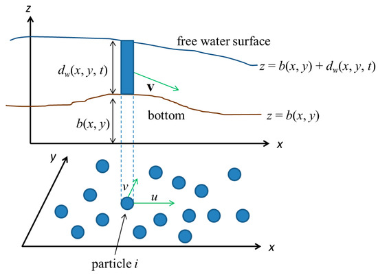
Figure 1.
Definition sketch of smoothed particle hydrodynamics (SPH) with shallow water equations.
2.2. Advection–Diffusion Equations
Solute transport processes are herein described by the advection–diffusion equations (ADEs), which are derived by Fischer et al. [36]. The ADEs in Lagrangian form are given as [30,31,33,34]
where C is the material concentration, Du is the diffusion coefficient, and is the density of particle. The concentration C is assumed to be dilute and the flow field is not affected by the concentration field.
2.3. SPH-SWEs-ADEs Model
2.3.1. Smoothed Particle Hydrodynamics (SPH) Formulation
In SPH, a scaled function and its gradient can be expressed by integral interpolation as follows:
where is the support domain, i.e., the influence domain of , is the kernel function, and h is the smoothing length.
Introducing a particle discretization of the continuous fluid, for the generic particle i, Equations (4) and (5) become
In the above equations, is the volume of particle j (=), is the mass of particle j (= in 1D and in 2D), and are the initial particle spacings in x and y directions, respectively, and N is the number of particles within the support domain of particle i. Hereafter, denotes and denotes .
To obtain higher order accuracy of the SPH gradient operator, we can adopt another two forms of SPH gradient operator, i.e., an antisymmetric form in Equation (8) and a symmetric form in Equation (9) [13].
Equation (8) is used to calculate the gradient of bottom elevation because should be zero when the terrain is flat. Equation (9) is used to calculate the inter force term (see Section 2.3.2.) due to its local conservation properties and intrinsic remeshing procedure [37].
In this work, the cubic spline kernel is chosen as the kernel function because it has better performance even when the particles become disordered [31].
where , = in 1D, and = in 2D.
2.3.2. Approximated Momentum Equations
In this study, we follow the work of [38] to approximate the momentum equations (Equation (2)) using a variational approach. The approximated momentum equations, which automatically yield the discrete conservation laws, are expressed as
where is the internal force and it can be evaluated by SPH formulation as [19]
In the above, the pressure force p is calculated based on the hydrostatic law as and is defined as
where , and is the number of space dimensions (1 in 1D and 2 in 2D).
Substituting into Equation (12) and adding the artificial viscosity to stabilize numerical solutions, Equation (12) thus becomes
In Equation (14), is the artificial dissipative formulation introduced in [17] and it is used to improve the stability during the simulations.
where , , ci is the pressure wave speed (=), , and .
Because of the free motion of fluid particles, the elevation and the Manning coefficient roughness of each particle are both allowed to vary with the location, and the interpolations of these two variables (Equations (16) and (17)) are performed with the help of the bottom particles. The bottom particles are different from the fluid particles. They are also introduced at the beginning of the simulation, but are not controlled by governing equations. Moreover, they are fixed and distributed on a Cartesian uniform grid during the whole simulation [20]. Hence, the bottom elevation and the Manning coefficient roughness of fluid particle i can be calculated respectively by
where bp denotes the bottom particles, denotes the corrected kernel [38], and Vbp is equal to in 1D and in 2D.
In addition, after calculating the bottom elevation for each fluid particle using Equation (16), the bottom elevation gradient of fluid particle i can be provided by using Equation (19).
where is the corrected gradient of kernel function [38].
By means of a correction matrix , the corrected gradient of kernel function can be written as
where is calculated by
2.3.3. Water Depth Evaluation
In this study, we calculate the water depth of each particle by the SPH summation operator shown in Equation (6) and thus the water depth of particle i can be expressed as
To obtain a more accurate SWEs solution, the smoothing length of particle i is allowed to vary in connection with water depth as follows:
where and are the initial density and smoothing length of particle i, respectively, and is the number of space dimensions.
Owing to the use of variable smoothing length, Equations (22) and (23) become a non-linear equation system. Hence, we use the Newton–Raphson iteration method to solve Equations (22) and (23). For more details, readers can refer to [18,39].
2.3.4. Approximated Advection–Diffusion Equations
Because the advection–diffusion equation involves a second spatial derivative, the integral approximation [28]
is used to discretize Equation (3) into the SPH interpolation form. After applying the integral approximation and particle approach, the RHS of Equation (4) becomes
where
and is a small constant to prevent singularities [40]. To maintain the continuity when Du is discontinuous over the computational domain, it is replaced by
Consequently, the SPH interpolation form of the ADE is
Equation (28) can be obtained with different derivations [29,31,33]. It is also suitable for the situations that the diffusion processes is anisotropic or inhomogeneous, and in such situations, the coefficient Du will be a tensor and has the elements of Duxx, Duxy, Duyx, and Duyy [30]. Most importantly the concentration field is computed at the same time with the flow field, which means that the SWEs and the ADE are solved together to obtain the modeling results. However, these two fields are not coupled because the solute concentration is assumed to be diluted; thus, the concentration field will not disturb the flow field.
2.3.5. Time Integration Scheme
To update particle positions, velocities and other physical variables, the leap-frog integration scheme is used due to its symplectic nature, which conserves the energy of dynamics systems, i.e., Equations (29)–(33).
Since SPH is an explicit method, the time step () is subject to the minimum between the Courant–Friedrichs–Lewy (CFL) condition and the diffusion condition:
where is the Courant number (= 0.25 in this study).
2.4. Boundary Conditions
2.4.1. In/Out-Flow Boundaries
The in/out-flow boundary conditions are required to predict flows with open boundaries. For imposing the open boundary conditions, two buffer zones are added next to the fluid domain: one at the upstream end and the other at the downstream end. In these zones, the Riemann invariants are used to calculate the water depths or water velocities at the in/out-flow boundaries according to the local Froude numbers [21,41]. As subcritical flow occurs at the inflow boundary, the inflow normal velocity is imposed and the inflow water depth can be calculated by
where the subscript B denotes variables at the boundary, the subscript I indicates the inner Riemann state values [21], and the subscript n denotes the normal direction.
The water depth is prescribed at the outflow boundary when the outflow is subcritical. Then, the unknown water velocity at the outflow boundary is required to be determined from Equation (36):
where the subscript t denotes the tangential direction.
Provided that the supercritical flow occurs at the inflow boundary, the water depth and the water velocity at the inflow boundary are imposed. The water depth and the water velocity do not need to be specified at the outflow boundary as the outflow is supercritical. The inner Riemann state value is computed by
where K denotes the inner Riemann state values of velocity or water depth, the superscript o represents the particle in open boundary buffer zones, and f indicates the particle in the fluid domain [21].
2.4.2. Wall Boundary
Since wall boundaries are involved in 2D flow cases, the modified virtual boundary particle method (MVBP) proposed in [20] is applied to implement the wall boundary conditions in this study. In MVBP, the so-called virtual particles, which are placed along wall boundaries, are introduced. Using local point-symmetry, each virtual particle can generate fictitious particles outside the physical domain. These fictitious particles have the same mass and densities that fluid particles inside the physical domain own but have opposite velocities to ones of those fluid particles. The fictitious particles involved in dealing with the momentum equations can prevent the fluid particles from penetrating wall boundaries.
3. Results and Discussion
In this section, six benchmark cases are given to evaluate the performance of the proposed model for handling steep gradient or discontinuous solutions. Steep concentration gradient cases concerning a top hat tracer and a unit-step tracer in 1D uniform flows and a circular tracer in a 2D uniform flow are adopted as the former three cases. Then, to consider the coupled steep concentration/velocity gradient cases, a periodic top hat tracer in a 1D transcritical flow and a unit-step tracer and a circular tracer respectively incorporating in 1D and 2D dambreak flows are conducted. All the numerical tests have been performed through an Intel(R) Core(TM) i7-2600 CPU 3.4 GHz personal computer (PC) equipped with a 4GB random access memory (RAM).
3.1. Steep Concentration Gradients
3.1.1. A Top Hat Tracer in a 1D Uniform Flow
The first study case is a 1D pure advection flow with a material concentration discontinuity in a 10,000 m long, flat and frictionless rectangle channel. The case has been used in [4,14] to study the impact of concentration discontinuity on the numerical dispersion. The initial top hat profile of concentration is provided by
The concentration boundary conditions are given as C(0, t) = 0 kg/m3 and C(10,000, t) = 0 kg/m3, while a water depth of 0.5 m and a water velocity of 0.5 m/s are prescribed as the inflow boundary condition. The total number of fluid particles is 100 and the initial time step is 100 s. The exact solution is given from [14].
Figure 2 shows the simulated results of concentration at t = 0 s, 4000 s, 8000 s and 12,000 s, respectively. Due to the Lagrangian nature, the non-linear term in ADEs can be handled intrinsically. Therefore, the oscillation or even negative concentrations in the vicinity of discontinuities induced by the discretized non-linear term in ADEs can be completely removed. Compared to the exact solutions, it can be seen that the present model gives good prediction on a top hat tracer in pure advection-dominated flows.
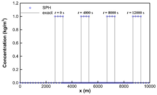
Figure 2.
The simulated profiles of concentration for the first study case.
3.1.2. A Unit-Step Tracer in a 1D Uniform Flow
A 1D uniform flow with various material diffusion effects in a 20,000 m long, flat, and rectangular channel without friction is served as the second study case [1]. Three diffusion coefficients of 0 m2/s, 2 m2/s, and 50 m2/s are adopted to give three various diffusion scenarios as advection-dominated, advection–diffusion, and diffusion-dominated, respectively. To solve ADEs, the initial conditions are provided as
C(0, t) = 1 kg/m3 and C(20,000, t) = 0 kg/m3 are given as the boundary conditions.
In this case, subcritical flows occur at the inflow and outflow boundaries, and the inflow water velocity of 0.5 m/s and the outflow water depth of 0.5 m are prescribed. 100 fluid particles are involved in solving SWEs and ADEs based on the initial time step = 200 s. The exact solution of this case is given in [1]. The simulated profiles of concentration with the diffusion coefficients of 0 m2/s, 2 m2/s, and 50 m2/s at t = 9600 s are respectively given in Figure 3. It can be found that the moving speed of the leading edge of Figure 3c owing to the effects of advection and diffusion is larger than the one of Figure 3a resulting from the effect of pure advection. Furthermore, the simulated results show good agreement against the exact solutions obtained in [33]. It can be concluded that the present model is capable of solving steep gradient or discontinuous solutions in concentration fields of advection-dominated, advection–diffusion, and diffusion-dominated problems. In Figure 3, the symbol Pe denotes the numerical Peclet number, which is defined as .
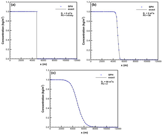
Figure 3.
The simulated profiles of concentration for the second study case: (a) Du = 0 m2/s, (b) Du = 2 m2/s, and (c) Du = 50 m2/s.
3.1.3. A Circular Tracer in a 2D Uniform Flow
For the third study case, a 2D rectangular channel is conducted to compare different material concentration evolution with time in a uniform flow with Du = 0 m2/s and 1 × 10⁵ m2/s. The rough channel of length 1000 m and width 400 m has the channel slope of 0.001. The Manning roughness coefficient is 0.0316 s/m1/3 representing the land use pattern of cultivated areas in floodplains. The water velocity uin of 2.929 m/s at the inflow boundary and the water depth of 5 m at the outflow boundary are given, while a circle region of radius of 50 m with material concentration 1 kg/m3 centered at (x, y) = (250 m, 200 m) is set to be the initial concentration condition.
Figure 4 shows the evolutions of concentration with time. The locations of the leading edge shown as a plus sign in Figure 4a are x = 300 m, 446 m, 652 m, and 891 m at t = 0 s, 50 s, 120 s, and 200 s, respectively. It can be seen that the displacements of the leading edge are approximately 50 s × uin, 120 s × uin, and 200 s × uin at t = 50 s, 120 s, and 200 s, respectively, because of the absence of the material diffusion. Next, Figure 4b gives the locations of the leading edge are x = 300 m, 476 m, 702 m and 945 m at t = 0 s, 50 s, 120 s, and 200 s, respectively. Since the transport behavior of the tracer is subject to the coupled advection and diffusion reaction, the displacements of the leading edge in Figure 4b are significantly larger than those in Figure 4a. Furthermore, Figure 4 also demonstrates that the present model still has the ability to preserve the shape of the tracer in 2D cases.
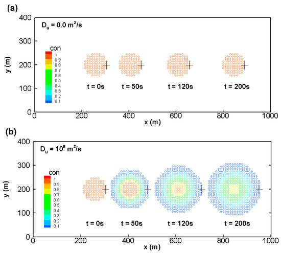
Figure 4.
The simulated profiles of concentration for the third study case: (a) Du = 0 m2/s and (b) Du = 105 m2/s.
3.2. Steep Concentration Gradients Coupled with Steep Velocity Gradients
3.2.1. A Periodic Top Hat Tracer in a 1D Transcritical Flow
In the fourth study case, a 1D rectangular channel flow subject to subcritical inflow and outflow conditions is considered. We investigate the spatial and temporal variations of a top hat tracer in a flow with a hydraulic jump. The tracer is released periodically at the inflow boundary and the diffusion coefficient equals to zero [8], i.e., Equation (40).
This rectangular channel of length 25 m is frictionless, and its elevations of channel bed can be described by
In addition, the water velocity of 0.435 m/s is specified as the inflow boundary condition, while the water depth of 0.33 m is given as the outflow boundary condition. The initial particle spacing of 0.01 m, i.e., 2500 fluid particles, is applied and the initial time step is 0.001 s. This is a steady case, and by the assumption of dilute concentration, the flow field is not affected by the concentration field, although they are solved at the same time. The exact solution is given in [8].
Figure 5 shows the simulated profiles of water depth, water velocity, and concentration. Due to a bump located at x = 10 m, subcritical inflow changes to supercritical and then returns to subcritical via a hydraulic jump. In comparison with the exact solutions, Figure 5a,b demonstrate that the simulated discontinuous solutions in water depth and water velocity are well consistent with the exact ones. Figure 5c illustrates the simulated profile of concentration at t = 194 s. Provided that a pure advection-dominated flow is considered in this case, the widths of top hat tracers vary with velocity gradients. For instance, the tracer near the bump has a larger width because of a higher velocity gradient. From the numerical outcomes of this case, we can exhibit that the shapes of top hat tracers can be preserved even in the cases of very steep velocity gradients.
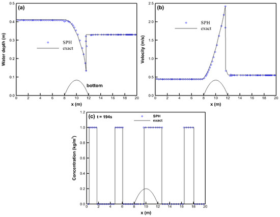
Figure 5.
The simulated profiles of the fourth study case: (a) water depth; (b) water velocity; and (c) concentration.
3.2.2. A Unit-Step Tracer in a 1D Dambreak Flow
A discontinuity in material concentration that occurs in a 1D dam break flow is adopted as the fifth study case. In addition to a dambreak flow over a dry bed without considering the diffusion effect on material concentration [5,6,7], the behavior of a dambreak flow over a wet bed involving the diffusion coefficient Du of 100 m2/s is also conducted herein [4].
In the first subcase, a rectangular, flat and frictionless channel has 50 m length. A water column of 20 m in length and 1 m in height with a material concentration of 1 kg/m3 is initially placed at the upstream boundary [22]. The initial particle spacing of 0.5 m and the initial time step of 0.1 s are used. Figure 6 is the simulated profiles of water depth and concentration at t = 2 s. The numerical solutions of water depth shown in Figure 6a give good agreement with the exact solution. Figure 6b illustrates that the concentration of each particle remains constant corresponding to Du = 0 m2/s.
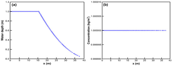
Figure 6.
The simulated profiles for the case of a dry-bed dambreak flow in the fifth study case: (a) water depth and (b) concentration.
Next, a wet-bed dambreak flow is conducted in a rectangular, flat, 2000 long channel without bed friction [4]. Initially, a 1000 m long and 1 m high water with a concentration of 0.7 kg/m3 is imposed at the upstream, while a 1000 m long and 0.2 m high water with a concentration of 0.5 kg/m3 is placed at the downstream. The initial particle spacing of 1 m and the initial time step of 1 s are used herein. The exact solution is given in [4]. Figure 7 shows the simulated profiles of water depth and concentration. In Figure 7, the proposed model provides good predictions in both water depth and concentration against the exact ones. Nevertheless, the entire simulated concentration profile given in [4] is smoother than the exact one. Thus, the present model can work well under the condition existing discontinuities both in the flow and concentration filed.
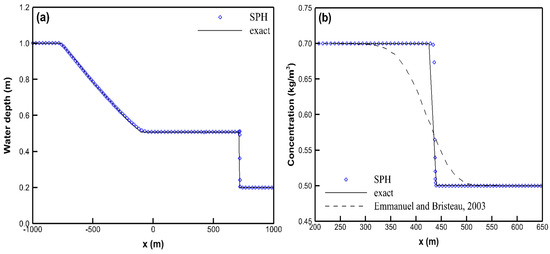
Figure 7.
The simulated profiles for the case of a wet-bed dambreak flow in the fifth study case: (a) water depth and (b) concentration.
3.2.3. A Circular Tracer in a 2D Dambreak Flow
A 2D dambreak flow with a 25 m long and 5 m wide terrain is adopted as the sixth study case. There is a conical mound with a bottom radius of 1 m and a height of 1 m centered at (x, y) = (12 m, 2.5 m) on the bed. Figure 8 gives the schematic view of the terrain. Two subcases with diffusion coefficients of 0 m2/s and 10 m2/s are considered. A water column of a 10 m length, a 5 m width, and a 0.7 m depth is imposed initially, and a circular tracer with a radius of 1 m and a concentration of 1 kg/m3 is released in the water column with its center located at (2.5 m, 5 m). The numerical test is performed using the initial particle spacing of 0.1 m in both x and y directions and the initial time step of 0.005 s.
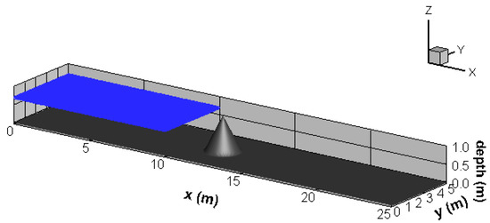
Figure 8.
Schematic view of the terrain in the sixth study case.
Figure 9 gives the plots of water depth and velocity vector at t = 4 s. It can be seen that a surge results from the dambreak flow blocked by the mound in Figure 9a and a flow separation occurs as the flow passes through the mound in Figure 9b. Then, Figure 10 and Figure 11 are the evolution of the simulated tracer with the diffusion coefficients of 0 m2/s and 10 m2/s, respectively. Since the solute transport is affected by the flow condition, the shape of the tracer is deformed as the flow approaches the mound and is also separated in Figure 10. By contrast, in Figure 11, besides the shape deformation and flow separation, the concentration of the tracer also occurs the diffusion phenomenon due to the non-zero diffusion coefficient. Based on the results in this study case, it shows that the present model can perform on solute transports with steep concentration gradients in steep velocity gradients flows.
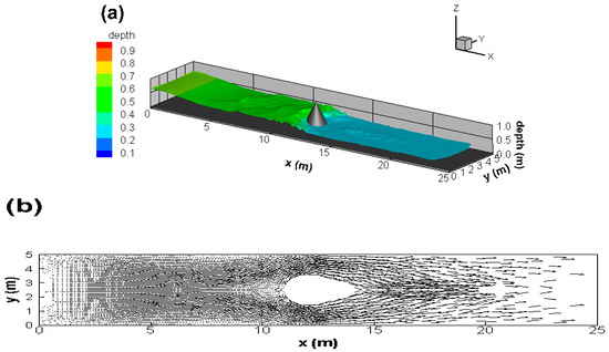
Figure 9.
The simulated profiles for the sixth study case: (a) water depth and (b) water velocity vector.
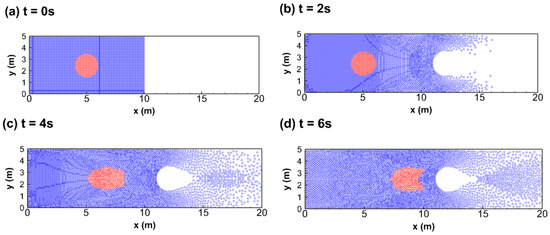

Figure 10.
The temporal simulated profiles of concentration for the case without material diffusion in the sixth study case: (a) 0 s, (b) 2 s, (c) 4 s, (d) 6 s, (e) 8 s, and (f) 10 s.
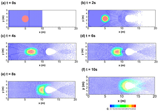
Figure 11.
The temporal simulated profiles of concentration for the case with material diffusion in the sixth study case: (a) 0 s, (b) 2 s, (c) 4 s, (d) 6 s, (e) 8 s, and (f) 10 s.
4. Conclusions
This study develops a new SPH-SWEs-ADEs model and shows its numerical advantages to solve steep gradient or discontinuous solutions in ADEs. Two major topics have been tested, including steep concentration gradients in the former three study cases and coupled steep concentration/velocity gradients in the latter three. From the outcomes of the entire numerical test cases, the present model can provide pretty good prediction on water depth/velocity and material concentration against the exact solutions. Because of the Lagrangian nature in SPH, one advantage of the model is to ensure complete mass concentration conservation in pure advection-dominated flows. The other advantage is that the numerical oscillation in concentration and the negative concentration, resulted from the discretization of the advection terms in SWEs and ADEs, can be totally avoided. Moreover, the present work can also provide a powerful ability to capture coupled steep velocity/concentration gradient flows. Therefore, it is suggested that the SPH-SWEs-ADEs model can be an alternative to investigate material transport problems in steep concentration/velocity gradient flows.
Acknowledgments
The authors are grateful for the financial support of this work provided by the Ministry of Science and Technology of Taiwan, under Grant No. MOST 105-2221-E-002-033-MY3.
Author Contributions
Yu-Sheng Chang and Tsang-Jung Chang contributed to the study design. Yu-Sheng Chang contributed to the data collection, performed the data analyses, and wrote the manuscript. Yu-Sheng Chang and Tsang-Jung Chang contributed to the discussion and interpretation of the results. All authors participated in reading and finalizing the manuscript.
Conflicts of Interest
The authors declare no conflict of interest.
References
- Zang, R.; Huang, K.; van Genuchten, M.T. An efficient Eulerian–Lagrangian method for solving solute transport problems in steady and transient flow fields. Water Resour. Res. 1993, 29, 4131–4138. [Google Scholar] [CrossRef]
- Leonard, B.P. The ULTIMATE conservative difference scheme applied to unsteady one-dimensional advection. Comput. Methods Appl. Mech. Eng. 1991, 88, 17–74. [Google Scholar] [CrossRef]
- Yeh, G.T.; Chang, J.R.; Thomas, E.S. An exact peak capturing and oscillation-free scheme to solve advection-dispersion transport equations. Water Resour. Res. 1992, 28, 2937–2951. [Google Scholar] [CrossRef]
- Emmanuel, A.; Bristeau, M.O. Transport of pollutant in shallow water: A two time steps kinetic method. ESAIM Math. Model. Numer. Anal. 2003, 37, 389–416. [Google Scholar]
- Begnudelli, L.; Sanders, B.F. Unstructured grid finite-volume algorithm for shallow-water flow and solute transport with wetting and drying. J. Hydraul. Eng. 2006, 132, 371–384. [Google Scholar] [CrossRef]
- Murillo, J.; García-Navarro, P.; Burguete, J. Analysis of a second-order upwind method for the simulation of solute transport in 2D shallow water flow. Int. J. Numer. Meth. Fluids 2008, 56, 661–686. [Google Scholar] [CrossRef]
- Burguete, J.; García-Navarro, P.; Murillo, J. Preserving bounded and conservative solutions of transport in one-dimensional shallow-water flow with upwind numerical schemes: Application to fertigation and solute transport in rivers. Int. J. Numer. Meth. Fluids 2008, 56, 1731–1764. [Google Scholar] [CrossRef]
- Fernández-Nieto, E.D.; Narbona-Reina, G. Extension of WAF type methods to non-homogeneous shallow water equations with pollutant. SIAM J. Sci. Comput. 2008, 36, 193–217. [Google Scholar] [CrossRef]
- Zhang, L.; Liang, Q.; Wang, Y.; Yin, J. A robust coupled model for solute transport driven by severe flow conditions. J. Hydro-Environ. Res. 2015, 9, 49–60. [Google Scholar] [CrossRef]
- Russell, T.; Celia, M. An overview of research on Eulerian–Lagrangian localized adjoint methods (ELLAM). Adv. Water Resour. 2002, 25, 1215–1231. [Google Scholar] [CrossRef]
- Obi, E.; Blunt, M. Streamline-based simulation of advective–dispersive solute transport. Adv. Water Resour. 2004, 27, 913–924. [Google Scholar] [CrossRef]
- Herrera, P.A.; Massabó, M.; Beckie, R.D. A meshless method to simulate solute transport in heterogenous porous media. Adv. Water Res. 2009, 32, 413–442. [Google Scholar] [CrossRef]
- Liu, G.R.; Liu, M.B. Smoothed Particle Hydrodynamics: A Meshfree Particle Method; World Scientific: Singapore, 2003. [Google Scholar]
- Devkota, B.H.; Imberger, J. Lagrangian modeling of advection-diffusion transport in open channel flow. Water Resour. Res. 2009, 45, W12406. [Google Scholar] [CrossRef]
- Chang, T.J.; Kao, H.M.; Chang, K.H. A new approach to model weakly nonhydroststic shallow water flows in open channels with smoothed particle hydrodynamics. J. Hydrol. 2014, 519, 1010–1019. [Google Scholar] [CrossRef]
- Chang, K.H.; Chang, T.J.; Chiang, Y.M. A novel SPH-SWEs approach for modelling supercritical and subcritical flows at open-channel junctions. J. Hydro-Environ. Res. 2016, 13, 76–88. [Google Scholar] [CrossRef]
- Ata, R.; Soulaïmani, A. A stabilized SPH method for inviscid shallow water flows. Int. J. Numer. Meth. Fluids 2005, 47, 139–159. [Google Scholar] [CrossRef]
- Rodriguez-Paz, M.; Bonet, J. A corrected smooth particle hydrodynamics formulation of the shallow-water equations. Comput. Struct. 2005, 83, 1396–1410. [Google Scholar] [CrossRef]
- Vacondio, R.; Rogers, B.D.; Stansby, P.K. Smoothed particle hydrodynamics: Approximated zero-consistent 2-D boundary conditions and still shallow-water tests. Int. J. Numer. Meth. Fluids 2012, 69, 226–253. [Google Scholar] [CrossRef]
- Vacondio, R.; Rogers, B.D.; Stansby, P.K. Accurate particle splitting smoothed particle hydrodynamics in shallow water with shock capturing. Int. J. Numer. Meth. Fluids 2012, 69, 1377–1410. [Google Scholar] [CrossRef]
- Vacondio, R.; Rogers, B.D.; Stansby, P.K.; Mignosa, P. SPH modeling of shallow flow with open boundaries for practical flood simulation. J. Hydraul. Eng. 2012, 138, 530–541. [Google Scholar] [CrossRef]
- Chang, T.J.; Kao, H.M.; Chang, K.H.; Hsu, M.H. Numerical simulation of shallow-water dam break flows in open channels using smoothed particle hydrodynamics. J. Hydrol. 2011, 48, 78–90. [Google Scholar] [CrossRef]
- Kao, H.M.; Chang, T.J. Numerical modeling of dambreak-induced flood and inundation using smoothed particle hydrodynamics. J. Hydrol. 2012, 448–449, 232–244. [Google Scholar] [CrossRef]
- Jian, W.; Liang, D.; Shao, S.; Chen, R.; Liu, X. SPH study of the evolution of water–water interfaces in dam break flows. Nat. Hazards 2015, 78, 531–553. [Google Scholar] [CrossRef]
- Pu, J.H.; Shao, S.; Huang, Y.; Hussain, K. Evaluations of SWEs and SPH numerical modelling techniques for dam break flows. Eng. Appl. Comp. Fluid 2013, 7, 544–563. [Google Scholar]
- Chang, T.J.; Chang, K.H. SPH modeling of one-dimensional nonrectangular and nonprismatic channel flows with open boundaries. J. Hydraul. Eng. 2013, 139, 1142–1149. [Google Scholar] [CrossRef]
- Chang, K.H.; Chang, T.J.; Sheu, T.W.H. Development of an upwinding kernel in SPH-SWEs model for 1D-trans-critical open channel flows. J. Hydro-Environ. Res. 2017, 15, 13–26. [Google Scholar] [CrossRef]
- Cleary, P.W.; Monaghan, J.J. Conduction modelling using smoothed particle hydrodynamics. J. Comput. Phys. 1999, 148, 227–264. [Google Scholar] [CrossRef]
- Tartakovskym, A.M.; Meakin, P.; Scheibe, T.D.; West, R.M.E. Simulations of reactive transport and precipitation with smoothed particle hydrodynamics. J. Comput. Phys. 2007, 222, 654–672. [Google Scholar] [CrossRef]
- Zhu, Y.; Fox, P.J. Smoothed particle hydrodynamics model for diffusion through porous media. Transp. Porous Med. 2001, 43, 441–471. [Google Scholar] [CrossRef]
- Monaghan, J.J. Smoothed particle hydrodynamics. Rep. Prog. Phys. 2005, 68, 1703–1759. [Google Scholar] [CrossRef]
- Hirschler, M.; Säckel, W.; Nieken, U. On Maxwell–Stefan diffusion in smoothed particle hydrodynamics. Int. J. Heat Mass Transf. 2016, 103, 548–554. [Google Scholar] [CrossRef]
- Aristodemo, F.; Federico, I.; Veltri, P.; Panizzo, A. Two-phase SPH modeling of advective diffusion processes. Environ. Fluid Mech. 2010, 10, 451–470. [Google Scholar] [CrossRef]
- Mayoral-Villa, E.; Alvarado-Rodríguez, C.E.; Klapp, J.; Gómez-Gesteira, M.; Sigalotti, L.D.G. Smoothed particle hydrodynamics: Applications to migration of radionuclides in confined aqueous systems. J. Contam. Hydrol. 2016, 187, 65–78. [Google Scholar] [CrossRef] [PubMed]
- Mead, J.L. The shallow water equations in Lagrangian coordinates. J. Comput. Phys. 2004, 200, 654–669. [Google Scholar] [CrossRef]
- Fischer, H.B.; List, E.J.; Koh, R.C.Y.; Imberger, J.; Brooks, N.H. Mixing in Inland and Coastal Waters; Academic Press: New York, NY, USA, 1979. [Google Scholar]
- Price, D.J. Smoothed particle hydrodynamics and magnetohydrodynamics. J. Comput. Phys. 2012, 231, 759–794. [Google Scholar] [CrossRef]
- Bonet, J.; Lok, T.S.L. Variational and momentum preservation aspects of smooth particle hydrodynamic formulations. Comput. Methods Appl. Mech. Eng. 1999, 180, 97–115. [Google Scholar] [CrossRef]
- Chang, T.J.; Chang, Y.S.; Chang, K.H. Modeling rainfall-runoff process using smoothed particle hydrodynamics with mass-varied particles. J. Hydrol. 2016, 543, 749–758. [Google Scholar] [CrossRef]
- Shao, S.; Lo, E.Y.M. Incompressible SPH method for simulating Newtonian and non-Newtonian flows with a free surface. Adv. Water Resour. 2003, 26, 787–800. [Google Scholar] [CrossRef]
- Federico, I.; Marrone, S.; Colagrossi, A.; Aristodemo, F.; Antuono, M. Simulating 2D open-channel flows through an SPH model. Eur. J. Mech. B Fluids 2012, 34, 35–46. [Google Scholar] [CrossRef]
© 2017 by the authors. Licensee MDPI, Basel, Switzerland. This article is an open access article distributed under the terms and conditions of the Creative Commons Attribution (CC BY) license ( http://creativecommons.org/licenses/by/4.0/).