Abstract
Water loss through leaking pipes constitutes a major challenge to the operational service of water utilities. In recent years, increasing concern about the financial loss and environmental pollution caused by leaking pipes has been driving the development of efficient algorithms for detecting leakage in water piping networks. Water distribution networks (WDNs) are disperse in nature with numerous number of nodes and branches. Consequently, identifying the segment(s) of the network and the exact leaking pipelines connected to this segment(s) where higher background leakage outflow occurs is a challenging task. Background leakage concerns the outflow from small cracks or deteriorated joints. In addition, because they are diffuse flow, they are not characterised by quick pressure drop and are not detectable by measuring instruments. Consequently, they go unreported for a long period of time posing a threat to water loss volume. Most of the existing research focuses on the detection and localisation of burst type leakages which are characterised by a sudden pressure drop. In this work, an algorithm for detecting and estimating background leakage in water distribution networks is presented. The algorithm integrates a leakage model into a classical WDN hydraulic model for solving the network leakage flows. The applicability of the developed algorithm is demonstrated on two different water networks. The results of the tested networks are discussed and the solutions obtained show the benefits of the proposed algorithm. A noteworthy evidence is that the algorithm permits the detection of critical segments or pipes of the network experiencing higher leakage outflow and indicates the probable pipes of the network where pressure control can be performed. However, the possible position of pressure control elements along such critical pipes will be addressed in future work.
1. Introduction
Losses occur in nearly all water distribution networks, even though the amount of water loss in each distribution system varies between countries and also from a particular distribution system to the other. In South Africa, for instance, almost 37% of the total input volume is lost through leaking pipeline [1]. In some well-developed and monitored water distribution systems, about 7% of the total input volume into the network is lost through leaking pipes [2]. Elsewhere, in less monitored systems, more than 50% of the total input volume into the network is lost through leaking pipes [3,4]. Therefore, water loss through leaking pipes constitutes a major challenge to the operational services of water utilities and is recognised as a costly problem strongly linked with interrupted service, waste of energy and natural resources [5,6,7]. Furthermore the quality of drinking water is a major concern. Leaks can introduce infections into the water distribution system under low pressure conditions [8,9]. Furthermore, the financial cost associated with leaking pipes is on the high side [1] and cannot be overlooked. Certainly, in water piping networks, minimising the leakage reduces the energy wasted in water pumping, reduces the carbon footprint while also increasing the revenue generated by the water utilities according to the relation [10]
where E is the energy consumption losses caused by water loss, is the leakage outflow at location i, is the piezometric head at location i, is the head loss between the pumps and the water loss location, g is the acceleration due to gravity, is the fluid density, T represents the duration of the water loss at location i and denotes the intensity of carbon dioxide emission.
It is evidence from Equations (1) and (2) that reducing the leakage outflows will save more energy being injected into the network, which directly reduces the emission of carbon dioxide into the atmosphere.
In water distribution networks (WDNs), leakage through pipes have evolved into two major types, namely burst type and background type leakages. The former is characterised by quick pressure drop and can be easily detected by measuring instruments such as pressure sensors stationed at specific locations along the length of the pipe. Burst type leakage often surfaces on the ground and are usually reported by public or utility workers. Thus, the repair time is faster. Background leakages are not detectable by measuring instruments, does not surface on the ground and can go unreported for a very long period of time posing a major threat to water utilities. They are not characterised by a sudden pressure drop compared to pipe burst. In water distribution networks, background leakage is hidden and runs continuously along the length of the pipes and can only be controlled by reducing pressures at the pipe node. Although most leakage detection methodology can only detect the most probable leaks in the network. Detecting leaks beyond a certain level is typically uneconomical [11]. Background leakages increases with the pipe internal pressure, therefore, reducing the excessive pressure at strategic point(s) in the network is worthwhile in reducing water losses due to the leaking pipes. However, identifying the segments or nodes of the network where such pressure control is required is very essential. Most of the existing methodologies developed can mainly be used for detecting, and in some cases, localising burst type leakages using flow meters and pressure sensors stationed at specific locations on the pipe. Background type leakages are not detected by measuring instruments, thus, the techniques based on pressure sensor data are not effective in detecting background type leakages. This paper focuses on the development of an algorithm for the detection and estimation of background leakage outflows in WDNs. The proposed algorithm will help in estimating and reporting the pipes of the network experiencing higher background leakage outflows. These pipes are considered as critical pipes by the algorithm and recommends pressure control along the critical pipes. Selecting the pipes of the network where pressure control and monitoring is required is a benefit of the proposed algorithm. The rest of the paper is organised as follows. In Section 2, the background of the study as well as some past research efforts are briefly discussed. In Section 3, the proposed leakage detection algorithm and its formulations are discussed. The results of its application to two different water distribution networks are discussed in Section 4 while Section 5 presents the conclusion and future works.
2. Background and Related Works
There is a clear evidence that water loss through leaking pipes in water distribution systems is complex and has a significant impact on the water system. Therefore, understanding the hydraulic characteristics of leakage flow and its control is crucial to designing an effective leakage detection methodology. A typical leakage programme usually starts with water audit based on the available flow measurements. To this objective, the network leakage is estimated based on either a 24 h zone measurement or minimum night flow (MNF) analysis [9]. The former requires an isolated area of the network supplied from one or two inflow points where the inflow into the area is measured and monitored. The minimum night flow analysis involves flow measurements in the period of least consumption typically between the hours of 02:00 h to 04:00 h [10]. During the MNF period, the water demand is usually very low, the head losses in each pipe get reduced, the pressure head and leakages reach their maximum values [10,12]. The water loss in the network is then obtained by subtracting the measured legitimate night use from the minimum night flow measurements. In a situation where the flow measurements in each pipe are not available, a hydraulic model with the capability of estimating the network leakage outflows could prove invaluable and go a long way in solving network leakage issues. Nevertheless, several definitions of leakage in WDNs exist. Initially, leakage outflow is attributed to a flow through an orifice [13]. The orifice flow equation described by Equation (3) is similar to the emitter features of the EPANET software widely used for WDNs hydraulic simulation [14].
where represents the leakage flow rate, is the leakage discharge coefficient, h denotes the pressure head, A, the area of the leak opening and n is the pressure to leakage exponent usually 0.5.
An improved leakage equation is proposed by May [15] where the leakage discharge is expressed in terms of the leakage opening area categorised as fixed area and variable area discharge (FAVAD). The FAVAD equation can be described by the following equation
where and are the fixed and variable leak opening area. Equations (3) and (4) are widely used in many research studies [16,17,18,19,20,21,22,23,24] to model and assesses network leakage outflows. However, the research attempts in [16,25] have proved that the use of the orifice flow equation can lead to misleading results based on some specific pipe conditions. For instance, Greyvenstein and van Zyl [16] reported that the orifice flow equation can lead to erroneous results when the model pipe is made of flexible material. Furthermore, when a negative pressure head occurs in the node of the network, a misleading results can also be given by the orifice flow equation [25].
Most of these research works are dedicated to burst type leakage with a particular leak opening area. For diffuse flow along the pipes (background leakage type) where the leak opening is not visible and the area cannot be estimated, the previous mentioned leakage models are not sufficient for estimating such type of leakage. While the methodology proposed by the authors in [26] may be used, it requires the knowledge of the total leakage for parameter calibration. Also, most of the methodologies developed in the past and recent years for leak detection and localisation can mainly be used for burst type leakage detection. These research efforts delve into the use of flow meters and pressure sensors stationed at specific locations on the pipe to detect leakages. For instance, Aksela et al. [27] uses the knowledge of reported leak experience with the data collected from flow meter readings to model and train the system. Farley et al. [28] presented a methodology for the detection of pipe burst, achieved by identifying the optimal locations of pressure sensors. Similarly, a sensor placement and leakage detection methodology to identify leakages in a WDS based on the deviation of sensor pressure from an estimated pressure was presented by Perez et al. [29]. Some other research works employ the benefits of the artificial intelligence system for leakage detection purposes [30,31,32]. Mounce et al. [30] proposed a leakage detection method based on an artificial neural network to harmonise data obtained from different sensors to classify different types of leakage in a WDS. The developed methodology is based on sensor time series data and thus requires a large monitoring database. In many of these research works, the location of the pipe burst is identified by using the arrival times and magnitudes of burst-induced transient waves at two or more points where the pressure sensors were stationed. Background type leakages are not detected by measuring instruments and go unreported for a long period of time, thus, the techniques based on pressure sensor data [28,29,30,31,33] are not effective in detecting background type leakages.
Background leakage is hidden and runs continuously along the length of the pipes in the network. It has been acknowledged that background leakage outflows posed the major threat to water utilities as they can neither be detected by measuring instruments nor surface on the ground for utility workers to notice. More recently, the battle of background leakage outflows has been a subject of discussion in the research community [34,35,36,37,38,39,40,41,42]. The current battle of background leakage assessment for water networks (BBLAWN) is an attempt to combine the methodologies for water distribution systems rehabilitation planning and sectorization [43,44,45,46,47,48,49] with pressure control management strategies [50,51,52,53,54,55,56,57,58,59,60,61,62] to achieve a reduced leakage ratio and lower the water distribution systems operational cost. Certainly, reducing the pipe pressure will significantly reduce the leakage outflows in the network. However, in the practical sense, it is not cost effective to reduce the entire network pressure. This is because some nodes of the network must have sufficient pressure to supplying and fully satisfying end users demands at the nodes. If the pressure head at a node is insufficient, a reduction in the water flowing from the tap is expected and, in the worst case, the discharge that can be drafted will be zero, regardless of the actual demand [25]. The proposed algorithm in this paper would help in specifying or determining which pipes of the network where such pressure control is necessary. Selecting the pipes of the network where pressure control and monitoring is required will be a benefit and will assist in supporting the BBLAWN for reduced leakage ratio in water network.
3. The Proposed Leakage Detection Algorithm
The process involved in the proposed leakage detection algorithm is briefly discussed in the pseudo code illustrated in Algorithm 1. The algorithm incorporates a leakage model into a classical water distribution network hydraulic simulation model to estimate the network flows, including leakage outflow at each node as well as at the pipe level. As shown in Algorithm 1, the process entails the hydraulic analysis of the water network and the leakage computation. The algorithm load and read the supplied water distribution network data and initialised. Afterwards, a hydraulic analysis is performed for such network based on the supplied data. The hydraulic analysis is achieved through modelling the water network topology and solving the resulting model using an iterative Newton-based methodology. During the hydraulic analysis of the network, the nodal leakage outflow is computed and the algorithm then checks if the estimated leakage outflow at the node is relatively low (or is less than a predefine tolerance), and if such is confirmed, it reports no leaking node as the flow rate in such node is less than tolerance or relatively low. Otherwise, it reports the leaking node number and search for all the pipes connected to this node. Thereafter, it computes the leakage flow in each pipe. Furthermore, it checks if the estimated leakage flow in each pipe is relatively high. Such pipe is tagged as critical pipes, the algorithm then recommends a pressure control along the critical pipes. In most cases, any pipe of the network with a relatively high background leakage flow above a predefine tolerance is tagged as a critical pipe where a pressure control or pressure adjustment is recommended.
| Algorithm 1: Proposed leakage detection algorithm |
| 1: Start { |
| 2: Load network parameters |
| 3: Read network parameters and initialise |
| 4: for node i= 1 to , (: The number of nodes in the network) |
| 5: for pipe j= 1 to b, (b: The number of pipes in the network) |
| Run hydraulic analysis and compute leakage vector |
| if (or relatively low) |
| Print “No leaking node” |
| else |
| i: Print “Leaking node ID” |
| ii: Search for pipes connected to this node |
| iii: Compute the pipe leakage vector |
| if (or relatively low) |
| Print “No leaking pipe” |
| else |
| Print “Leaking pipe ID” |
| Tag leaking pipe as critical pipes and report critical pipe ID |
| Display “Pressure control recommended along the critical pipe with ID...” |
| end if |
| end if |
| 6: end for j |
| 7: end for i |
| 8: Stop } |
3.1. WDN Topology and Model Formulation
A water distribution network (WDN) can be represented by a connected graph with a set of edges and a set of nodes. The former consist of pipes, pumps, and valves. The basic hydraulic equations describing the flow in a water distribution system are governed by two basic principles; namely the principle of mass continuity in the node and energy conservation around the hydraulic loop. For any water piping networks comprising of b number of branches or pipes, n number of junction nodes, number of source nodes or fixed-grade nodes (nodes with known pressure heads), and number of load nodes (nodes with unknown pressure heads), the total number of nodes in the network is . The mass continuity equation can be written for each node, and the energy conservation equation can be written for any loop. Using graph theory, the continuity equation at any given node may be expressed as
where, represents the column vector of nodal injection or demand and is the column vector of pipe flows while denotes the node-pipe connectivity matrix of dimension (), whose elements are derived from
The node-pipe connectivity matrix C may be decomposed into two sub-matrices as
where, denotes the source node-pipe connectivity matrix of dimension () relating to the node with known pressure and is the load node-pipe connectivity matrix of dimension () relating to the node with unknown pressure. If the pressure is given at the source nodes and demand (loads) are given at the load nodes, by decomposing Equation (5) and writing the flow at the load nodes only
Furthermore, the energy conservation concerns the pressure drop across the pipes. For a closed loop, the pressure drop across the pipes may be expressed as
where represents the loop-pipe incidence matrix and m is the number of loops. The elements of matrix D are derived from
In Equation (9), represents the pressure drop vector across the pipes.
The energy conservation may also be expressed as
where denotes the column vector (dimension ()) of the source pressure and is the vector of the load pressure of dimension ().
Another set of equations necessary for the solution of a piping network are the pipe-flow equations which relate the pressure drop across a given pipe to the flow in that pipe. Consider a network element shown in Figure 1, with two end nodes i and g, the pressure drop due to the friction of the flow of water with the pipe wall is generally expressed as
where and are the pressure at both ends of the pipe, is the flow in the pipe j and k represents the pipe hydraulic resistance.

Figure 1.
A network element.
Substituting into Equation (11)
If we define a matrix A as
Equation (13) may be written as
Both Equations (8) and (14) are the steady state hydraulic model to be solved to estimate the pipe flow and the pressure at the load node, given the pressure at the source node and the demand at the load node. The system of equations described by Equation (15) is partly linear and partly non-linear.
Equation (15) can be solved by an iterative method. The matrix A is a diagonal matrix of dimension () whose elements are derived from the pressure drop relation as
Both and k depend on the pressure drop or head loss model used [14,63]. k is the vector of pipe hydraulic resistance, it depends on parameters as
where represents the pipe equivalent roughness coefficient, D is the pipe diameter, L is the pipe length and is the the pressure exponent whose value depends on the pressure drop or head loss model used (1.85 for Hazen-William (HW) and 2 for both Darcy-Weisbach (DW) or Chezy-Manning (CM) head loss model) [14,63].
In any event, using the DW or the HW model, the hydraulic resistance for the pipe may be expressed as
for DW model, and
for HW model. In Equation (18), , and g represent the frictional factor of the pipe and the acceleration due to gravity. In Equation (19), denotes the Hazen-William friction coefficient for the pipe. The variables and in both equations represent the length and diameter of the pipe.
The pipe frictional factor in Equation (18) depends on the Reynolds number as well as the equivalent roughness factor and can be estimated using the Colebrook equation, the Jain’s formula or any other related expressions.
It is important to emphasize that in order to account for leakage flow in the model represented by Equation (15), the demand vector q comprises of the normal demand and the nodal leakage flows. That is,
where denotes the vector of the normal nodal demand and is the vector of the nodal leakage flow.
3.2. WDN Hydraulic Model Solution
The classical pipe network analysis problems is to find a set of flow Q and the pressure P in a water distribution network with the input (nodal injection or demand) and the source pressure known. The system of equation in (15) may be solved applying Newton-Raphson iterative method. Define as
with , therefore,
The system of non-linear equation of may be solved by Newton-Raphson (NR) iterative method. Thus, at every iteration “”, the NR method is described as
where J is the Jacobian matrix of the function . For the function above, the Jacobian matrix is given by
where is a diagonal matrix whose elements are the partial derivatives of pressure drop component given as . The elements of matrix D for all the pipes in the network may be obtained as
From Equation (23),
Multiplying both sides of Equation (28) by , one may write
Replacing in Equation (30), therefore
Define matrix B (network admittance matrix) as
Equation (31) may the be rewritten as
Therefore, the estimate of the pressure at each iteration “” is obtained as
The admittance matrix B used is highly sparse, symmetric and must be handled using an efficient sparsity techniques. From Equation (28) as well, the estimate of the pipe flow at each iteration “” may be expressed as
The Equations (33) and (34) give the iterative solution of the system of non-linear equation describe in Equation (15). The Newton-Raphson method is known to give a fast convergence provided a good initial solution is available [64]. The derived solution is closely similar to those obtained by [65,66,67]. The matrices and are derived from the topology of the water distribution networks.
3.3. Integrating a Leakage Model
In water distribution networks (WDNs), leakage occurs at the nodes as well as along the pipes. Previous research works have shown that leakage depends on the network pressure, therefore, the pressure-leakage relationship is defined in the vector . It should be noted that background leakage flow occurs continuously along the length of a pipe. If the leakage flow along a pipe j is denoted by , then may be expressed as
where, is the background leakage discharge coefficient of the pipe, is the length of the pipe, is the leakage-pressure exponent reported to be equivalent to 1.18 for background leakage [68]. is the pressure in pipe j computed as the mean of the pressure values at its end nodes.
In matrix form, defining a vector as the vector of the leakage flow along all the pipes, then
where, is the vector of empirical constants relating to background leakage parameter, is the vector of the pipe length, and is the vector of the average pressures along the pipes. The vector may be expressed using the topological incidence matrix as
where,
is the absolute of the network incidence matrix C, which gives a matrix of ones. is the vector of the load node pressures.
If the vector of the nodal leakage is denoted by , then the elements of may be computed from the topological incidence matrix as
4. Numerical Examples
The applicability of the developed leakage detection algorithm was demonstrated on two different water distribution networks derived from literature. For both networks, [34] was assumed for the pipes. All computations and the hydraulic analysis are done in MATLAB software environment.
4.1. Numerical Example 1
Figure 2 shows the schematic diagram of the case study water network used for the numerical example 1. The network consist of 1 supply node (tank node) and 8 demand or load nodes (non-tank nodes). The supply node (node 1) and the load nodes (which indexes from node 2 to node 9) are interconnected by a series of pipes with different length and diameter. The data for each pipe and node in this network is shown in Table 1 and Table 2.
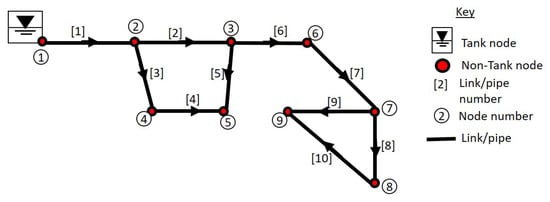
Figure 2.
The schematic diagram of the case study network 1 (Adapted from: [69]).

Table 1.
Pipe data for the case study network 1 [69].

Table 2.
Node data for the case study network 1 [69].
In Figure 3, the profile of the nodal leakage outflow for the case study network 1 is presented. From the figure, it may be seen that nodes 2, 3, 4 and 5 has the highest leakage outflow while the least leakage outflow occurs in nodes 7, 8 and 9. Therefore, nodes 2, 3, 4 and 5 may be initially considered as critical nodes of the network where pressure adjustment could be needed. The pipes connected to these nodes are pipes 1, 2, 3 for node 2, pipes 2, 5, 6 for node 3, pipes 3 and 4 for node 4 while pipes 4 and 5 are connected to node 5. If the leakage flow along any or all of these pipes is relatively high, therefore, a pressure control is required in such node of the network.
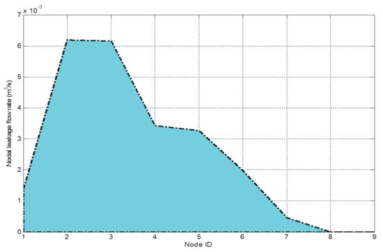
Figure 3.
The profile of the nodal leakage outflow for the case study network 1.
Figure 4 shows the pattern of the discharge and the leakage flow rate in each pipe for the case study network 1. From the figure, it may be observed that pipe 1 has the highest flow rate. This is obvious as it is directly connected to the supply node (node 1) while the most downstream pipe (Pipe number 10) has the least flow rate. In terms of the leakage flow, pipes 8, 9 and 10 has the least leakage flow rates among other pipes in the network. The highest leakage flow rate is noticed in pipes 2 and 4. Also, the leakage flow in pipes 4 and 5 is higher than their corresponding actual discharges. Therefore, these pipes together with pipe 1 may be tagged as critical pipes for this network where pressure adjustment or pressure control is needed.
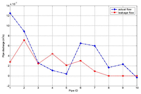
Figure 4.
The pattern of the pipe discharge and leakage flow for the case study network 1.
In Figure 5, the profile of the estimated flow rate in each pipe before and after leakage outflow is presented. It is evidence that the flow rate in most of the pipes is reduced when leak occurs along pipes. In pipes 8, 9 and 10, their flow rate remain the same due to the fact that the leakage flow in those pipes is zero. In most cases, the presence of leak reduces the flows in each pipe.
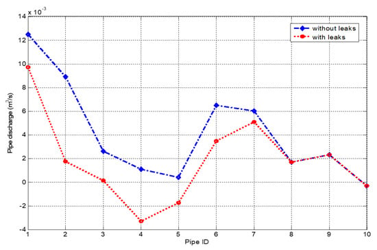
Figure 5.
The Pattern of the pipe flow rate before and after leak for the case study network 1.
To further establish which pipes of the network contribute mostly to water loss. The water loss volume through each pipe is computed for two minutes and the results obtained are illustrated in Figure 6. Minutes analysis was considered because the actual transients in water distribution systems tend to have high frequencies with time periodicities of seconds or minutes, by far smaller than the time increments of interest, generally hours [70]. Considering Figure 6, it may be observed that pipe 2 (connected between nodes 2 and 3) and pipe 4 (connected between nodes 4 and 5) are experiencing higher water loss volume. With evidence from Figure 3 that initially tagged nodes 2, 3, 4 and 5 as critical nodes with higher leakage outflow, thus, with the water loss volume result, one may safely conclude that pipes 2 and 4 experiencing the greatest loss volume and which are connected to these nodes can be tagged as critical pipes. Therefore, the pressure at their corresponding nodes may be adjusted or reduced to minimise the water loss rate.
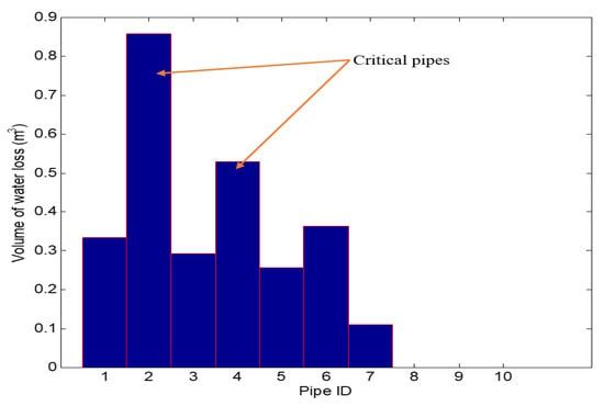
Figure 6.
Water loss volume in each pipe for the case study network 1.
4.2. Numerical Example 2
Figure 7 shows the schematic diagram of the case study water network used for the numerical example 2. As can be seen in Figure 7, the network consist of 1 supply node (tank node) and 45 demand or load nodes (non-tank nodes). The supply node (node 1) and the load nodes (which indexes from node 2 to node 46) are interconnected by a series of pipes with different length and diameter. The data for each pipe and node in this network is shown in Table 3 and Table 4.
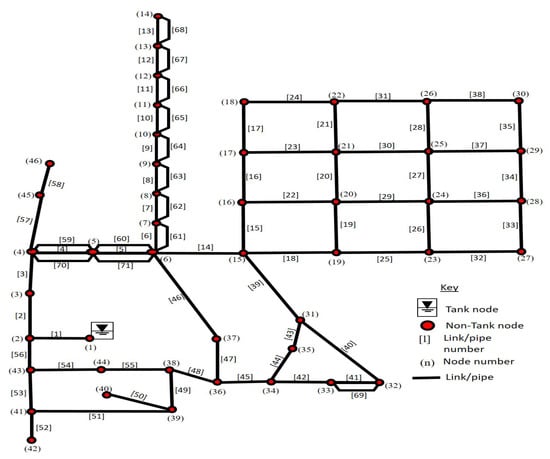
Figure 7.
The schematic diagram of the case study network 2 (Adapted from: [71]).

Table 3.
Pipe data for the case study network 2 [71].

Table 4.
Node data for the case study network 2 [71].
Figure 8 shows the leakage profile for each node of the case study network 2, including the supply node. It is evidence that nodes 5, 6 and 41 of this network are experiencing the highest leakage outflow and may be considered as being the most critical nodes of the network. Thus, pressure control might be needed to minimise the leakage outflow through these nodes as well as the overall leakage in the network. The pipes connected to these nodes include pipes (4, 5, 59, 60, 70, 71) for node 5, pipes (5, 6, 14, 46, 60, 61, 71) for node 6, and pies (51, 52, 53) to node 41 respectively. Any pipe connected to these nodes with a relatively high leakage flow rate requires a pressure control at either one or both of its end nodes.
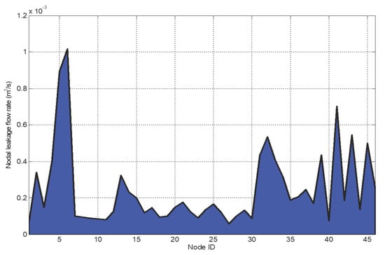
Figure 8.
The profile of the nodal leakage outflow for the case study network 2.
In Figure 9, the pattern of the nodal demand and the leakage level at the nodes is illustrated. The leakage level is compared to the actual demand at the nodes of the network. It is obvious that even though the background leakage outflow at each node is lower than the actual nodal demand, the leakage level can still pose a threat to the available flow at each consumer end. The flow delivered to the consumer end will be compromised due to the presence of the nodal leakage flow, though not significant.
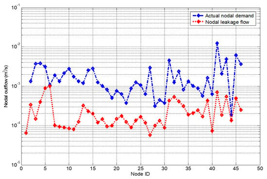
Figure 9.
Nodal demand vs the leakage outflow for each node for the case study network 2.
Figure 10 concerns the pattern of the pipe discharge and the leakage flow rate in each pipe. In a similar manner to the case study network 1, pipe 1 has the highest flow rate as it is directly connected to the supply node while pipe 38 has the least flow rate. Furthermore, it is evident that the leakage flow is relatively low compared to the actual flow in each pipe apart from pipes 24, 38, 41 and 89 having leakage flow higher than their actual discharge. Aside from searching for the pipes with the highest leakage flow, any pipe of the network having a leakage flow greater than its actual discharge (such as pipes 24, 38, 41 and 89) of the case study network 2, may also be considered to be a critical pipe.
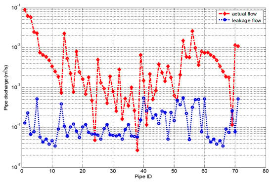
Figure 10.
The pattern of the pipe discharges and the leakage flow in each pipe for the case study network 2.
The result presented in Figure 11 shows that the leakage flow in each pipe of the case study network 2 is almost negligible when compared to the actual discharge in each pipe. Figure 11 illustrates the pipe discharge with and without the event of leak. The pattern of both flows (with and without leak) is almost the same because the leakage flow in each of the pipe is relatively low and almost negligible compared to the actual pipe discharge.
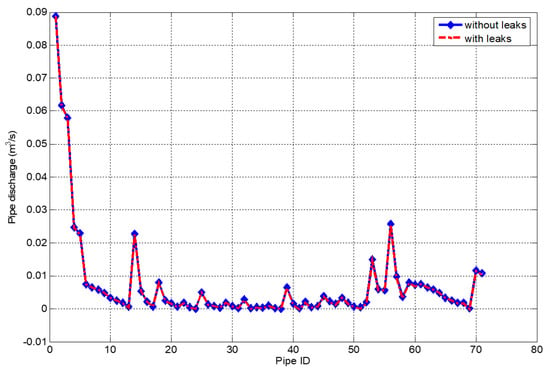
Figure 11.
The pattern of the pipe discharges before and after leakage flow for the case study network 2.
In Figure 12, the water loss volume through each pipe is illustrated. This figure shows which branches of the network contribute mostly to the water loss volume. Some pipes (branches) of the network are experiencing higher water loss when computed for two minutes of flow. Pipes (5, 13, 40, 51, 52, 53, 57, 58, 60 and 71) are experiencing higher water loss volume (greater than 0.04 ), and may be considered to be critical pipes. A noteworthy evidence from this figure is that even though the leakage flow rate in these pipes (the considered critical pipes) are relatively low compared to the actual discharge, those pipes still contribute largely to water loss volume in the network. Therefore, pressure control in these pipes will minimise the leakage flow rate through these pipes, which adversely reduce the volume of water loss in the entire network.
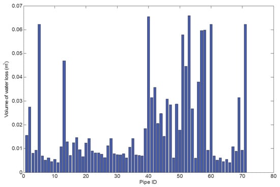
Figure 12.
The volume of water loss through each pipe for the case study network 2.
In Table 5, a comparison of the solution convergence of the hydraulic analysis stage of the algorithm for the case study networks is presented. An error tolerance of [72] was used as the convergence criterion. It is observed that the hydraulic simulation method used has a faster convergence; 4 iterations for a network with 71 pipes.

Table 5.
Comparison of the solution/convergence history for the case study networks.
5. Conclusions
Water distribution networks (WDNs) are disperse in nature with numerous number of nodes and pipes. Consequently, identifying the segments of the network and the exact leaking pipelines connected to these segments where higher background leakage outflow occurs is a challenging task. In this work, an algorithm for detecting and estimating background leakage outflow in water distribution networks is developed and presented. The algorithm integrates a leakage model into a WDN hydraulic model for solving the network leakage flow. The applicability of the developed algorithm is demonstrated on two water supply networks. The results presented show that the developed algorithm permits the detection and estimation of critical segments or branches of the network experiencing higher background leakage outflow and a point of the network where pressure control may be performed. However, localising the exact point on the pipe where higher background leakage outflow occurs and the possible position of pressure control elements along such critical pipes will be addressed in future work. A noteworthy evidence is that, the algorithm may be used to assess the state of water networks.
Acknowledgments
This research work was supported in part by the Tshwane University of Technology, Pretoria and the Council for Scientific and Industrial Research (CSIR), Pretoria, South Africa.
Author Contributions
Adedeji Kazeem conceived the original idea of the study within the development of his Doctorate degree. This idea was thoroughly discussed with Adedeji’s Doctoral supervisors, the three other co-authors. Adedeji Kazeem was in charge of the problem formulation and manuscript draft while Yskandar Hamam help with some improvement in the mathematical formulations. The manuscript was thoroughly reviewed by Yskandar Hamam while Adnan M. Abu-Mahfouz and Bolanle T. Abe also suggested some improvements in the paper.
Conflicts of Interest
The authors declare no conflict of interest.
References
- McKenzie, R.S.; Siqalaba, Z.; Wegelin, W. The State of Non-Revenue Water in South Africa; Report No. TT522/12; Water Research Commission: Lynnwood Manor, Pretoria, South Africa, 2012. [Google Scholar]
- Beuken, R.; Lavooij, C.; Bosch, A.; Schaap, P. Low leakage in the Netherlands confirrmed. In Proceedings of the Water Distribution Systems Analysis Symposium 2008 (WDSA 2008), Kruger National Park, South Africa, 17–20 August 2008; pp. 1–8. [Google Scholar]
- Lambert, A. International Report: Water Losses Management and Techniques, Water Science and Technology: Water Supply; IWA Publishing: London, UK, 2002; Volume 2, pp. 1–20. [Google Scholar]
- Mamlook, R.; Al-Jayyousi, O. Fuzzy sets analysis for leak detection in infrastructure systems: A proposed methodology. Clean Technol. Environ. Policy 2003, 6, 26–31. [Google Scholar] [CrossRef]
- Colombo, A.F.; Karney, B.W. Energy and costs of leaky pipes: Toward comprehensive picture. J. Water Resour. Plan. Manag. 2002, 128, 441–450. [Google Scholar] [CrossRef]
- Abu-Mahfouz, A.M.; Hamam, Y.; Page, P.R.; Djouani, K.; Kurien, A. Real-time dynamic hydraulic model for potable water loss reduction. Procedia Eng. 2016, 154, 99–106. [Google Scholar] [CrossRef]
- Xu, Y.; Li, W.; Ding, X. A stochastic multi-objective chance-constrained programming model for water supply management in xiaoqing river watershed. Water 2017, 9, 378. [Google Scholar]
- Ostfeld, O.; Uber, J.G.; Salomons, E.; Berry, J.W.; Hart, W.E.; Phillips, C.A.; Watson, J.P.; Dorini, G.; Jonkergouw, P.; Kapelan, Z.; et al. The battle of the water sensor networks (BWSN): A design challenge for engineers and algorithms. J. Water Resour. Plan. Manag. 2008, 134, 556–568. [Google Scholar] [CrossRef]
- Puust, R.; Kapelan, Z.; Savic, D.; Koppel, T. A review of methods for leakage management in pipe networks. Urban Water J. 2010, 7, 25–45. [Google Scholar] [CrossRef]
- Wu, Z.; Farley, M.; Turtle, D.; Kapelan, Z.; Boxall, J.; Mounce, S.; Dahasahasra, S.; Mulay, M.; Kleiner, Y. Water Loss Reduction, 1st ed.; Bentley Institute Press: Exton, PA, USA, 2011. [Google Scholar]
- Gupta, R.; Nair, A.G.R.; Ormsbee, L. Leakage as pressure-driven demand in design of water distribution networks. J. Water Resour. Plan. Manag. 2016, 142, 04016005. [Google Scholar] [CrossRef]
- Ribeiro, R.; Sousa, J.; Marques, A.S.; Simoes, N.E. Locating leaks with trustrank algorithm support. Water 2015, 7, 1378–1401. [Google Scholar] [CrossRef]
- Wiggert, D.C. Unsteady flows in lines with distributed leakage. J. Hydraul. Div. 1968, 95, 143–162. [Google Scholar]
- Rossman, L.A. Epanet 2 User’s Manual, US Environmental Protection Agency; Water Supply and Water Resources Division, National Risk Management Research Laboratory: Cincinnati, OH, USA, 2000; Volume 45268.
- May, J. Pressure dependent leakage. In World Water and Environmental Engineering; WEF Publishing Inc.: London, UK, 1994. [Google Scholar]
- Greyvenstein, B.; Van Zyl, J.E. An experimental investigation into the pressure leakage relationship of some failed water pipes. J. Water Supply 2007, 56, 117–124. [Google Scholar] [CrossRef]
- Van Zyl, J.E.; Cassa, A. Modelling elastically deforming leaks in water distribution Pipes. J. Hydraul. Eng. 2013, 140, 182–189. [Google Scholar] [CrossRef]
- Cassa, A.; Van Zyl, J.E. Predicting the head-leakage slope of cracks in pipes subject to elastic deformations. J. Water Supply 2013, 62, 214–223. [Google Scholar] [CrossRef]
- Van Zyl, J.E. Theoretical modelling of pressure and leakage in water distribution systems. Procedia Eng. 2014, 89, 273–277. [Google Scholar] [CrossRef]
- Muranho, J.; Ferreira, A.; Sousa, J.; Gomes, A.; Marques, A.S. Pressure-dependent demand and leakage modelling with an EPANET extension WaterNetGen. Procedia Eng. 2014, 89, 632–639. [Google Scholar] [CrossRef]
- Schwaller, J.; Van Zyl, J.E.; Kabaasha, A. Characterising the pressure-leakage response of pipe networks using the FAVAD equation. Water Sci. Technol. 2015, 15, 1373–1382. [Google Scholar] [CrossRef]
- Ssozi, E.; Reddy, B.; Van Zyl, J.E. Numerical investigation of the influence of viscoelastic deformation on the pressure-leakage behaviour of plastic pipes. J. Hydraul. Eng. 2015, 142, 04015057. [Google Scholar] [CrossRef]
- Adedeji, K.B.; Hamam, Y.; Abe, B.T.; Abu-Mahfouz, A.M. Burst leakage—Pressure dependency in water piping networks: Its impact on leak openings. In Proceedings of the IEEE Africon Conference, Cape Town, South Africa, 18–20 September 2017; pp. 1550–1555. [Google Scholar]
- Van Zyl, J.E.; Lambert, A.; Collins, R. Realistic modelling of leakage and intrusion flows through leak openings in pipes. J. Hydraul. Eng. 2017, 143, 04017030. [Google Scholar] [CrossRef]
- Todini, E. A More Realistic Approach to the Extended Period Simulation of Water Distribution Networks. In Advances in Water Supply Management; Swets and Zeitlinger Publishers: Lisse, The Netherlands, 2003. [Google Scholar]
- Covelli, C.; Cozzolino, L.; Cimorelli, L.; Della Morte, R.; Pianese, D. A model to simulate leakage through joints in water distribution systems. Water Sci. Technol. 2015, 15, 852–863. [Google Scholar] [CrossRef]
- Aksela, K.; Aksela, M.; Vahala, R. Leakage detection in a real distribution network using a SOM. Urban Water J. 2009, 6, 279–289. [Google Scholar] [CrossRef]
- Farley, B.; Mounce, S.; Boxall, J. Field testing of an optimal sensor placement methodology for event detection in an urban water distribution network. Urban Water J. 2010, 7, 345–356. [Google Scholar] [CrossRef]
- Perez, R.; Puig, V.; Pascual, J.; Peralta, A.; Landeros, E.; Jordanas, L. Pressure sensor distribution for leak detection in Barcelona water distribution network. Water Sci. Technol. 2009, 9, 715–721. [Google Scholar] [CrossRef]
- Mounce, S.R.; Khan, A.; Wood, A.S.; Day, A.J.; Widdop, P.D.; Machell, J. Sensor fusion of hydraulic data for burst detection and location in a treated water distribution system. Inf. Fusion 2003, 4, 217–229. [Google Scholar] [CrossRef]
- Mounce, S.R.; Machell, J. Burst detection using hydraulic data from water distribution systems with artificial neural networks. Urban Water J. 2006, 3, 21–31. [Google Scholar] [CrossRef]
- Islam, M.S.; Sadiq, R.; Rodriguez, M.J.; Francisque, A.; Najjaran, H.; Hoorfar, M. Leakage detection and location in water distribution systems using a fuzzy-based Methodology. Urban Water J. 2011, 8, 351–365. [Google Scholar] [CrossRef]
- Perez, R.; Sanz, G.; Puig, V.; Quevedo, J.; Escofet, M.A.C.; Nejjari, F.; Meseguer, J.; Cembrano, G.; Tur, J.M.M.; Sarrate, R. Leak localization in water networks: A model-based methodology using pressure sensors applied to a real network in Barcelona. IEEE Control Syst. 2014, 34, 24–36. [Google Scholar] [CrossRef]
- Giustolisi, O.; Berardi, L.; Laucelli, D.; Savic, D.; Walski, T.; Brunone, B. Battle of background leakage assessment for water networks (BBLAWN) at WDSA conference 2014. Procedia Eng. 2014, 89, 4–12. [Google Scholar] [CrossRef]
- Price, E.; Ostfeld, A. Battle of background leakage assessment for water networks using successive linear programing. Procedia Eng. 2014, 89, 45–52. [Google Scholar] [CrossRef]
- Vassiljev, A.; Koppel, T.; Puust, R. Background leakage assessment for BBLAWN. Procedia Eng. 2014, 89, 111–117. [Google Scholar] [CrossRef]
- Tolson, B.; Khedr, A. Battle of background leakage assessment for water networks (BBLAWN): An incremental savings approach. Procedia Eng. 2014, 89, 69–77. [Google Scholar] [CrossRef]
- Shafiee, M.E.; Berglund, A.; Berglund, E.Z.; Brill, E.D., Jr.; Mahinthakumar, G. Parallel evolutionary algorithm for designing water distribution networks to minimize background leakage. J. Water Resour. Plan. Manag. 2015, 142, C4015007. [Google Scholar] [CrossRef]
- Eck, B.J.; Arandia, E.; Naoum-Sawaya, J.; Wirth, F.R. Decomposition approach for background leakage assessment: BBLAWN instance. J. Water Resour. Plan. Manag. 2015, 142, C4015009. [Google Scholar] [CrossRef]
- Iglesias-Rey, P.; Martinez-Solano, F.; Melia, D.M.; Martinez-Solano, P. BBLAWN: A combined use of best management practices and an optimization model based on a pseudo-genetic algorithm. Procedia Eng. 2014, 89, 29–36. [Google Scholar] [CrossRef]
- Laucelli, D.; Meniconi, S. Water distribution network analysis accounting for different background leakage models. Procedia Eng. 2015, 119, 680–689. [Google Scholar] [CrossRef]
- Berardi, L.; Laucelli, D.; Ugarelli, R.; Giustolisi, O. Hydraulic system modelling: Background leakage model calibration in Oppegård municipality. Procedia Eng. 2015, 119, 633–642. [Google Scholar] [CrossRef]
- Creaco, E.; Alvisi, S.; Franchini, M. A multi-step approach for optimal design and management of the C-town pipe network model. Procedia Eng. 2014, 89, 37–44. [Google Scholar] [CrossRef]
- Yoo, D.G.; Kang, D.; Jun, H.; Kim, J.H. Rehabilitation priority determination of water pipes based on hydraulic importance. Water 2014, 6, 3864–3887. [Google Scholar] [CrossRef]
- Giustolisi, O.; Berardi, L.; Laucelli, D.; Savic, D.; Kapelan, Z. Operational and tactical management of water and energy resources in pressurized systems: Competition at WDSA 2014. J. Water Resour. Plan. Manag. 2015, 142, C4015002. [Google Scholar] [CrossRef]
- Saldarriaga, J.; Paez, D.; Bohorquez, J.; Paez, N.; Paris, J.P.; Rincon, D.; Salcedo, C.; Vallejo, D. Rehabilitation and leakage reduction on C-town using hydraulic criteria. J. Water Resour. Plan. Manag. 2015, 142, C4015013. [Google Scholar] [CrossRef]
- Tolson, B.A.; Maier, H.R.; Simpson, A.R.; Lence, B.J. Genetic algorithms for reliability-based optimization of water distribution systems. J. Water Resour. Plan. Manag. 2004, 130, 63–72. [Google Scholar] [CrossRef]
- Yoo, D.G.; Jung, D.; Kang, D.; Kim, J.H. Seismic-reliability-based optimal layout of a water distribution network. Water 2016, 8, 50. [Google Scholar] [CrossRef]
- Campbell, E.; Izquierdo, J.; Montalvo, I.; Perez-Garcia, R. A novel water supply network sectorization methodology based on a complete economic analysis, including uncertainties. Water 2016, 8, 179. [Google Scholar] [CrossRef]
- Hindi, K.S.; Hamam, Y. Locating pressure control elements for leakage minimization in water supply networks: An optimization model. Eng. Optim. 1991, 17, 281–291. [Google Scholar] [CrossRef]
- Hindi, K.S.; Hamam, Y. Pressure control for leakage minimization in water supply networks part 1: Single period models. Int. J. Syst. Sci. 1991, 22, 1573–1585. [Google Scholar] [CrossRef]
- Hindi, K.S.; Hamam, Y. Pressure control for leakage minimization in water supply networks: Part 2. multi-period models. Int. J. Syst. Sci. 1991, 22, 1587–1598. [Google Scholar] [CrossRef]
- Hindi, K.S.; Hamam, Y. An optimisation model for setting pressure controllers to minimise leakage in pipe networks. In Optimization-Based Computer-Aided Modelling and Design; Springer: Berlin, Germany, 1992; pp. 116–125. [Google Scholar]
- Hamam, Y.; Hindi, K.S. Optimised on-line leakage minimisation in water piping networks using neural nets. In Proceedings of the IFIP Working Conference, Dagschul, Germany, 28 September–1 October 1992; pp. 57–64. [Google Scholar]
- Araujo, L.; Ramos, H.; Coelho, S. Pressure control for leakage minimisation in water distribution systems management. Water Resour. Manag. 2006, 20, 133–149. [Google Scholar] [CrossRef]
- Roshani, E.; Filion, Y. WDS leakage management through pressure control and pipes rehabilitation using an optimization approach. Procedia Eng. 2014, 89, 21–28. [Google Scholar] [CrossRef]
- Page, P.R.; Abu-Mahfouz, A.M.; Yoyo, S. Real-time adjustment of pressure to demand in water distribution systems: Parameter-less p-controller algorithm. Procedia Eng. 2016, 154, 391–397. [Google Scholar] [CrossRef]
- Covelli, C.; Cozzolino, L.; Cimorelli, L.; Della Morte, R.; Pianese, D. Optimal location and setting of PRVs in WDS for leakage minimization. Water Resour. Manag. 2016, 30, 1803–1817. [Google Scholar] [CrossRef]
- Covelli, C.; Cimorelli, L.; Cozzolino, L.; Della Morte, R.; Pianese, D. Reduction in water losses in water distribution systems using pressure reduction valves. Water Sci. Technol. 2016, 16, 1033–1045. [Google Scholar] [CrossRef]
- Page, P.R.; Abu-Mahfouz, A.M.; Yoyo, S. Parameter-less remote real-time control for the adjustment of pressure in water distribution systems. J. Water Resour. Plan. Manag. 2017, 48. [Google Scholar] [CrossRef]
- Page, P.R.; Abu-Mahfouz, A.M.; Mothetha, M. Pressure management of water distribution systems via the remote real-time control of variable speed pumps. J. Water Resour. Plan. Manag. 2017, 48. [Google Scholar] [CrossRef]
- Adedeji, K.B.; Hamam, Y.; Abe, B.T.; Abu-Mahfouz, A.M. Pressure management strategies for water loss reduction in large-scale water piping networks: A review. In Advances in Hydroinformatics-SimHydro 2017; Springer: Berlin, Germany, 2017; pp. 1–9, in press. [Google Scholar]
- Basha, H.; Kassab, B. Analysis of water distribution systems using perturbation Method. Appl. Math. Model. 1996, 20, 291–297. [Google Scholar] [CrossRef]
- Hamam, Y.; Brameller, A. Hybrid method for the solution of piping networks. Proc. Inst. Electr. Eng. 1971, 118, 1607–1612. [Google Scholar] [CrossRef]
- Todini, E.; Pilati, S. A gradient algorithm for the analysis of pipe networks. In Computer Applications in Water Supply: Volume 1, Systems Analysis and Simulation; Research Studies Press Ltd.: Baldock, UK, 1988; pp. 1–20. [Google Scholar]
- Piller, O.; Bremond, B.; Poulton, M. Least action principles appropriate to pressure driven models of pipe networks. In Proceedings of the World Water and Environmental Resources Congress, Philadelphia, PA, USA, 23–26 June 2003; pp. 1–15. [Google Scholar]
- Giustolisi, O.; Laucelli, D.; Berardi, L.; Savic, D. Computationally efficient modelling method for large scale water network analysis. J. Hydraul. Eng. 2012, 138, 313–326. [Google Scholar] [CrossRef]
- Germanopoulos, G. A technical note in the inclusion of pressure dependent demand and leakage terms in water supply network models. Civ. Eng. Syst. 1985, 2, 171–179. [Google Scholar] [CrossRef]
- Piller, O.; Van Zyl, J. Pressure-driven analysis of network sections supplied via high-lying nodes. In Proceedings of the Computing and Control in the Water Industry, Integrating Water Systems, Sheffield, UK, 1–3 September 2009. [Google Scholar]
- Todini, E. Towards realistic extended period simulations (EPS) in looped pipe network. In Proceedings of the Water Distribution Systems Analysis Symposium, Kruger National Park, South Africa, 17–20 August 2008; pp. 1–16. [Google Scholar]
- Kumar, S.M.; Narasimhan, S.; Bhallamudi, S.M. State estimation in water distribution networks using graph-theoretic reduction strategy. J. Water Resour. Plan. Manag. 2008, 134, 395–403. [Google Scholar] [CrossRef]
- Elhay, S.; Piller, O.; Deuerlein, J.; Simpson, A.R. A robust, rapidly convergent method that solves the water distribution equations for pressure-dependent models. J. Water Resour. Plan. Manag. 2015, 142, 1–26. [Google Scholar] [CrossRef]
© 2017 by the authors. Licensee MDPI, Basel, Switzerland. This article is an open access article distributed under the terms and conditions of the Creative Commons Attribution (CC BY) license (http://creativecommons.org/licenses/by/4.0/).