1. Introduction
This study aimed to develop a methodology for the automated and appropriate design of a long-throated modular flume. Water measurement in distribution networks, especially in open channels, is essential for rational water use [
1,
2]. The importance of controlling water use, especially irrigation water, is even greater during periods of drought, such as those frequently experienced in southern Spain.
Traditional irrigation systems, where water is distributed through canals and irrigation ditches, do not often have gauging elements. This is partly due to the use of weirs with low modular limits. On the contrary, long-throated flumes have a design that allows them to reach high modular limits of up to 80% [
3], which makes them ideal for use in open channel flow.
Attempts have been made to design a measuring flume for free flow with characteristics similar to those of the Venturi in pressurized conduits. The prototype that achieved the greatest similarity was the so-called Parshall measuring flume [
4], which has been in use since the second half of the 20th century. The Parshall flume is a critical depth flume, but its different models do not satisfy the laws of similarity; consequently, each has a different flow equation and their parameters, only valid for that structure, must be obtained experimentally [
5].
The first studies on modular or critical-flow flumes were not conducted until the last quarter of the 20th century [
5,
6]. The term “modular” assumes that a critical regime occurs in the throat section, such that the flow rate can be obtained by simply reading the head upstream.
Several studies have been published more recently, including studies proposing a flow equation considering a triangular broad-crested weir based on the approach velocity [
7]. Other studies have analyzed the flow through a trapezoidal cut-throated flume [
8]. Compared with our work, using the approach velocity in the first case is more complex than measuring the upstream water depth. In the second case, a flume without a throat, although cheaper, loses one of the most important properties of a long-throated flume; i.e., uniform flow cannot be considered to exist in the narrowing.
Other design procedures for modular flumes have been proposed (e.g., Ref. [
9], based mainly on the WinFlume program in its latest version [
10]). The fundamental difference with the methodology presented here is that, in our case, the parameters for the control section are directly provided with a more precise procedure than, for example, that of [
11].
The main objective of this study was to provide a quick and automated design using a spreadsheet that allows direct estimation of the dimensions of the narrowed section of a long throat channel, side slope, and bottom width. We chose the modular limit, sill height, and throat length based on the characteristics of the channel where the flume was to be installed and that guaranteed flow measurement in the desired flow range. This long-throated flume was used to measure the flow rate in a drainage canal of a flood-irrigated rice field. Since the inflow rate to the field is known, the water consumed can be determined, and from there, irrigation practices can be implemented to reduce the high water requirements of rice.
2. Materials and Methods
Rice is grown under anaerobic conditions via flood irrigation, which maintains a constant water depth during most of the crop cycle; thus, water requirements reach a very high volume of about 12,000 m
3/ha. The described procedure was applied to the design of a flume to measure the flow of water through a drainage channel of a 15 ha plot of land that is located in the marshes (“marismas”) of the Guadalquivir valley, southwestern Spain (37°2′58″ N; 5°58′32″ W), and cultivated with rice. Its control allowed us to establish practices to reduce the high water consumption. The drained discharge varies depending on the inflow, crop growth phase, and drying periods [
12]; thus, measuring it requires the use of a device that can cover a wide range of flow rates, which, in this case, has been estimated to be between Q
m = 0.02 and Q
M = 0.05 m
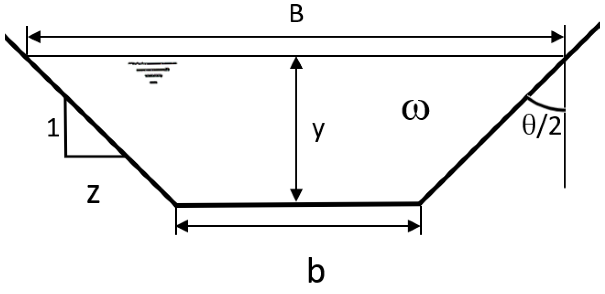
3/s. The characteristics of the trapezoidal section drainage channel are as follows: b
c = 0.4 m; z
c = 1.1798 (θ/2 = 49.71°) (see
Figure 1); S (slope) = 0.002; n = 0.025 (Manning’s roughness coefficient).
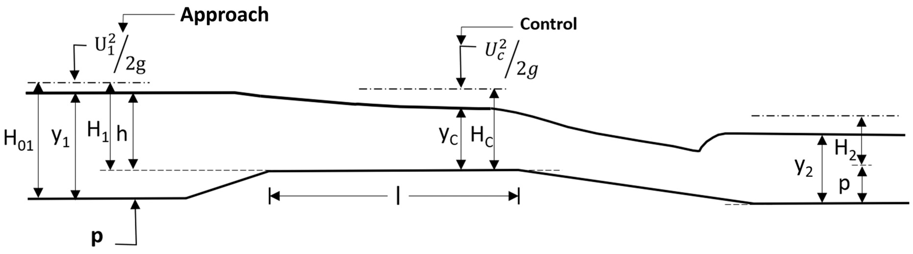
The long-throated flume consists of a convergent–divergent structure that, interposed in a subcritical permanent free flow, can impose the critical depth, y
c, in the throat section; that is, it is a critical depth flume (see
Figure 2). Under this condition, a biunivocal relationship between the flow rate and the upstream gaged head h in the approach section can be established (see
Figure 2). This operation is called modular [
3,
13].
The acceptance of uniform flow in both the upstream section and the narrowed section facilitates the theoretical development, and hence, the throat must be of sufficient length in relation to the upstream head to be able to accept uniform flow in the throat. It should also not be too long since energy losses would increase proportionally.
Channel narrowing, whether due to bed elevation by a sill, wall approach (convergence of side walls and bottom contraction), or both, causes an increase in upstream head, resulting in additional energy losses ∆H = H
2 − H
1 through the flume, which should be sufficient to produce a critical regime in the throat [
13]. The limit of utilization depends on the ratio (H
2/H
1), called the submergence ratio, which should not exceed the modular limit, L. The modular limit corresponds to the condition in which the downstream current begins to influence the upstream current. Above a certain value of L, modular flow in each long-throated flume will not be possible since the head h in the approach section no longer determines the flow rate biuniquely. The relationship L(Q) must be determined experimentally for each long-throated flume [
3].
With proper design of the convergence and divergence sections, especially the latter, few energy losses will occur, and L will be high, which characterizes these flumes [
3].
The geometrical shape of the throat can be diverse, with trapezoidal, rectangular, parabolic, and circular sections being common. The procedure presented has been particularized for the trapezoidal section, but it can be generalized to any other cross-section shape.
The design of the trapezoidal-shaped control section is very complex since it is necessary to calculate two parameters, b
t and z
t (see
Figure 2). For this purpose, the authors of [
3] started from the flow interval to be measured (Q
M; Q
m) and, applying Manning’s Equation (1), obtained the hydraulic depths, y
M, y
m, with which they would circulate through the channel.
where ω is the channel cross-sectional area (m
2), R is the hydraulic radius (m), and S is the channel slope.
Neglecting the velocity head in a first approximation, where H
1 = h = y
1−p (see
Figure 1), the authors had a pair of initial values (Q
M, H’
M) and (Q
m, H’
m) with which to proceed to calculate b
t and z
t. Each narrowed section design was created for different values of p, ranging from zero to a maximum of 15% of the hydraulic depth in the upstream section, y
1M, to avoid overflow.
However, when the long-throated flume is installed, the upstream head H
1 > H’
1; i.e., the energy values are higher than those considered by these authors. An estimate of the energy value upstream can be determined by considering that the uniform flow that exists in the channel without the flume is restored downstream of the flume, and, therefore, the actual upstream head is H
1 = (H
2/L), with L being the modular limit. Consequently, the values of H with which the design would start are as follows:
In a first approximation, we start from the assumption of frictionless flow, H = H
1 = H
c, and the flow rate is obtained as follows:
where Cg is the shape coefficient, which is calculated as follows:
with
with
The final expression Cg (C
H) is practically impossible to obtain analytically; hence, it is easier to fit an equation to the pairs of values (Cg, C
H), which, representing these values, is observed to be of a linear type (Equation (6))
The fit gives us the values of m and n. Combining Equations (3) and (6) leads to the Equation (7)
which, particularized for the pairs of values (Q, H’), results in the Equations (7a) and (7b):
Solving this system of equations gives us the values of
and
in the Equations (8) and (9).
For viscous flow, the values of m and n remain unchanged, while the new values of b
t and z
t are obtained using the flow equation where a new coefficient, C
d, is introduced (Equation (3a)):
where C
d is the discharge coefficient obtained, for instance, from Equation (10) [
13]:
The throat length l is calculated from Equation (11):
Following the same procedure as before, but now for the pair of values (Q, H), the values of bottom width, b
t, and side slope, z
t, of the throat section are obtained (Equations (8a) and (9a)):
Finally, the application of the complete discharge Equation (3b) [
3] serves to verify the design:
where C
v is the approach velocity coefficient calculated as in (12) and (13):
with ω
1 = approach section area
The flow rate is calculated by applying Equation (3b) after measuring the upstream gaged head h. However, the coefficients Cg and Cd depend on H; thus, initially, the calculations begin with H = h. Once the first value of the flow rate, Q’, is obtained, the next value, Hn, is calculated as and so on until the flow rate value is repeated, which occurs after very few iterations.
A solution widely used because it is constructively very easy to realize involves keeping the side slope of the approach section in the throat section: z
t = z
c. Under this assumption, there is only one unknown, b
t, to be calculated. This can be obtained using a single pair of values (Q
M, H
M):
In this situation, when the circulating flow rate is Qm, Equation (14) for (Qm, Hm) must also be fulfilled, allowing Hm to be calculated while maintaining the same value for bt. The ratio (Hm2/Hm1) must be less than L for the proposed design to be accepted. However, for lower values of L within the range considered, it is possible that no solution to the problem can be found since higher head losses are required, and the narrowing is only achieved by raising the sill, p, which now can no longer be equal to zero.
3. Results
3.1. General Calculations
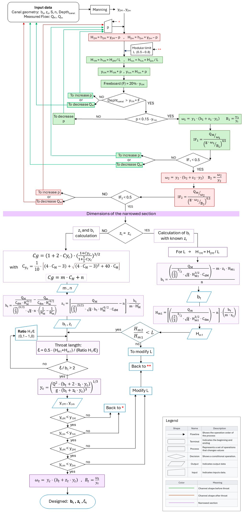
The calculation process was developed on an Excel spreadsheet following the process shown in the flow chart in
Appendix A. The design recommendations were taken from [
9,
14]. The preliminary results of this work were presented at a scientific conference [
15].
The design steps for the narrowed section started with the choice of the flow rate range to be measured; in our case, Qm = 0.02 and QM = 0.05 m3/s. Next, a value of the sill height p was selected, which, in this example, varied between 0 and 0.015 m. Later, the water levels downstream were calculated using Manning’s equation, and the energy values were obtained. For a given value of the modular limit, L, whose variation was set between 0.5 and 0.8, the energy and depth values upstream of the flume were calculated so that the maximum value of the sill height p must be less than 15% of the depth of the approach section, y1M. Subsequently, a freeboard of 0.2 y1M was adopted, and a check was performed to determine whether the canal bank had been overcome. If any of these assumptions were not met, p must be decreased; otherwise, the maximum flow that could be measured would be less than QM. The Froude number, F, was also confirmed to be less than 0.5 in the approach section for both QM and Qm; otherwise, p would have to be increased or QM would have to be decreased.
Next, b
t and z
t were calculated using Equations (8a) and (9a) and the throat length, l, was obtained using Equation (11) so that the ratio (H/l) was kept between 0.1 and 1.0; l should be greater than twice the bottom width, b
t, to ensure that uniform flow was achieved in the throat. Finally, it was verified that the critical regime was reached at the throat; otherwise, it would be necessary to go back to the beginning and increase p. A 1:3 ratio was adopted for the upstream ramp and a softer 1:6 ratio was adopted for the downstream ramp due to the higher risk of boundary layer separation. Recent works [
16,
17] have experimentally studied the influence of the convergence transition in this type of flume. Their results could also be considered in our design without altering the proposed model.
For each combination of p, L, and H/l, the values of b
t and z
t that meet all the requirements of the flow chart shown in
Appendix A were obtained. In total, 240 (6 × 4 × 10) possible different sizes of narrowed sections have been designed in which a critical regime can be reached in the throat when the flow rate is between Q
M and Q
m.
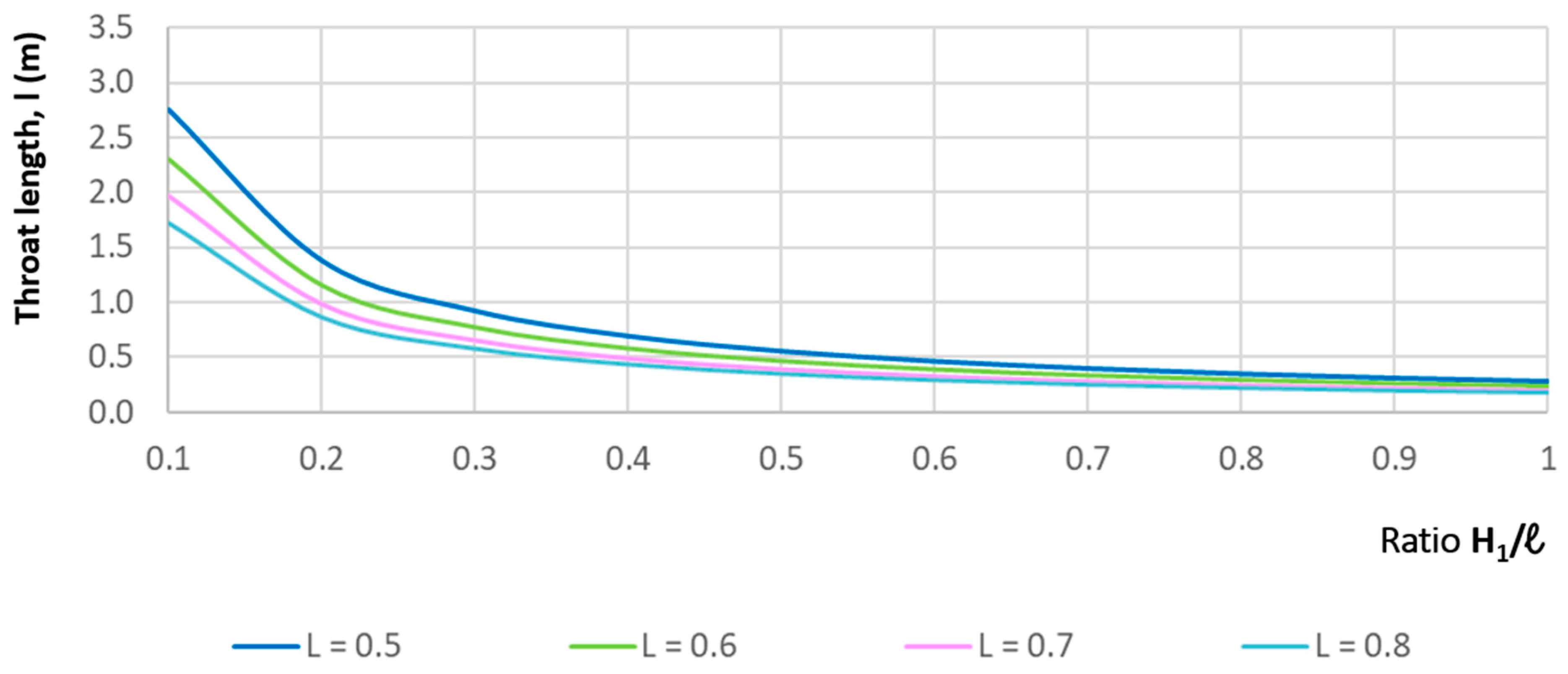
Some of the results obtained are presented graphically. For example,
Figure 3 shows the relationship between the throat length, l, and the ratio H/l for p = 0.012 m and for all values of L. The higher the L, i.e., the lower the head losses, the lower the throat length; however, the throat length remains practically constant for H/l > 0.5. The influence of p is small, although the higher the sill height, the shorter the throat length.
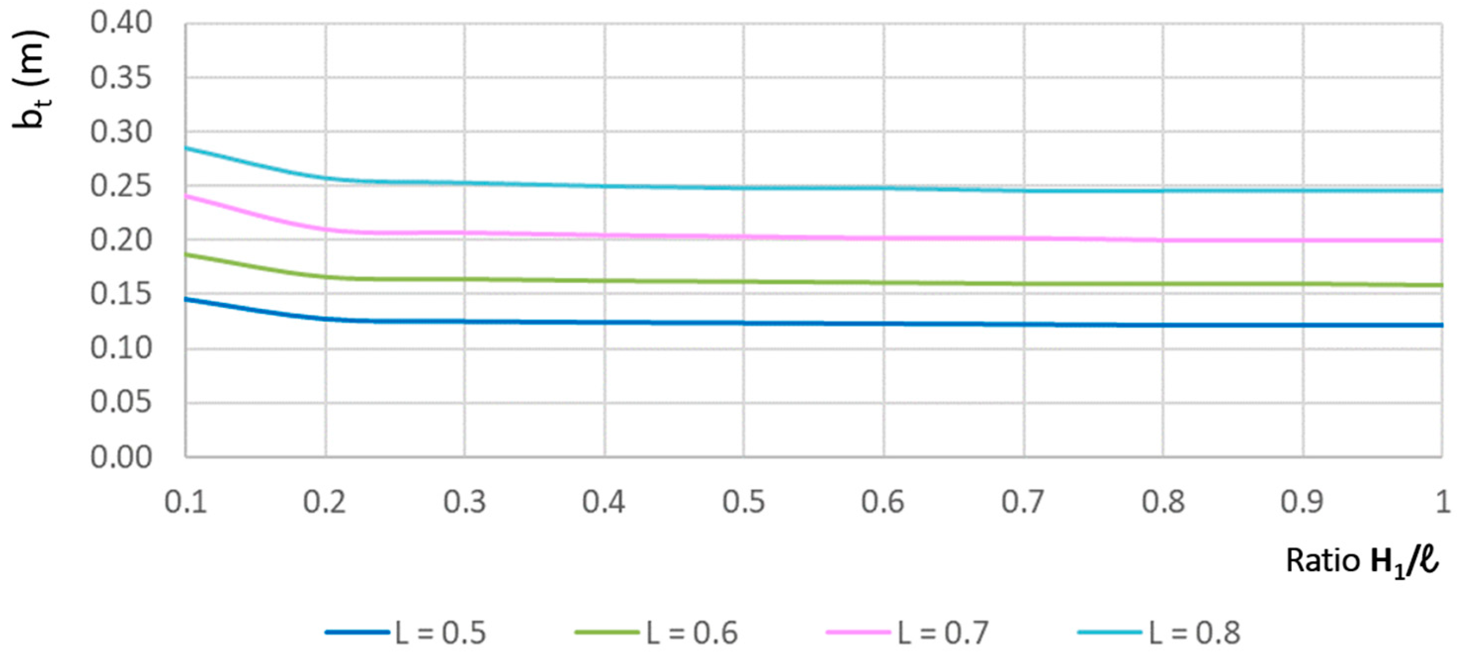
Figure 4 shows the relationship between b
t and H/l for p = 0.012 and for all values of L. Obviously, the value of b
t increases as the value of L increases. When H/l > 0.2, b
t decreases slightly, although it tends to be constant. The variation in b
t is very pronounced below H/l < 0.2, evidence of the non-uniformity of the flow. Additionally, as expected, the value of b
t increases at higher p.
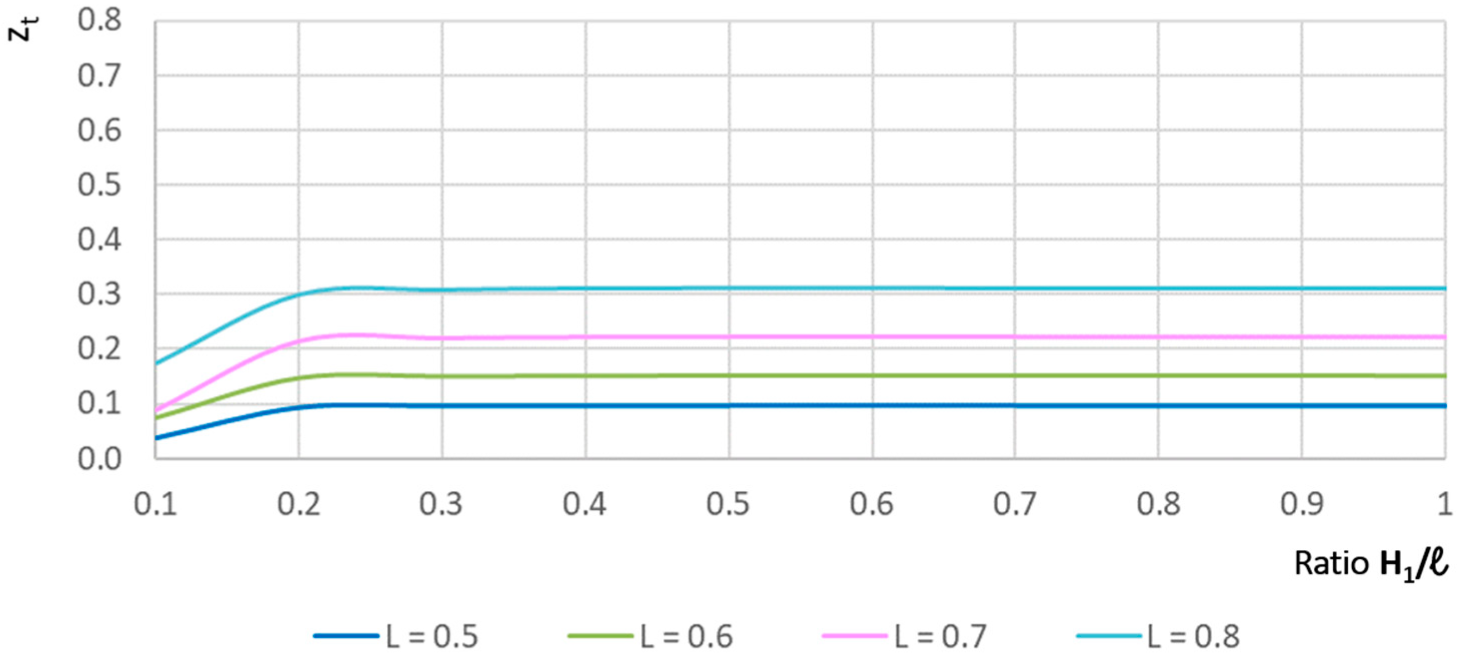
The relationship between z
t and H/l is shown in
Figure 5 for p = 0.012 m. In this case, a large variation in z
t also appears for values of H/l < 0.2, and thereafter, z
t rises and remains practically constant. The value of z
t increases at higher L values, implying that the throat section becomes larger since the head losses are smaller. Increasing p also decreases the value of z
t.
As an example, some of the designs shown in
Figure 3,
Figure 4 and
Figure 5 were randomly selected for various combinations of L, p, and H/l and checked using the WinFlume program. The outputs of this software are shown in
Table 1. In all cases, the results of the evaluation of the design criteria are satisfactory.
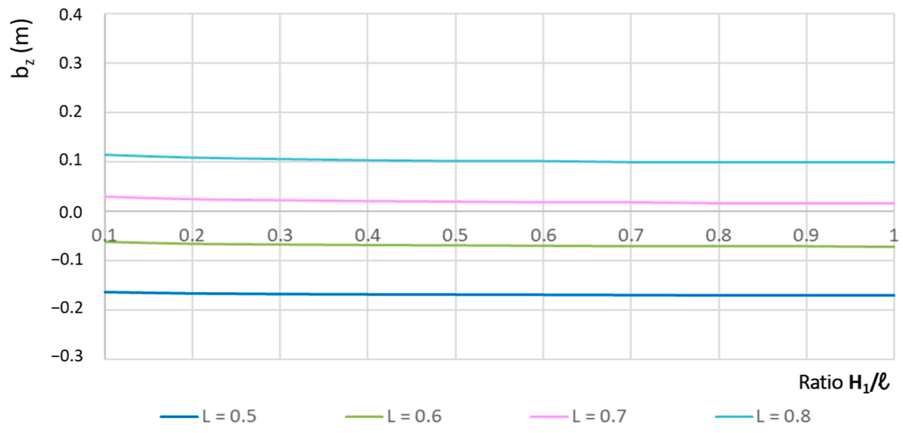
It is quite common to design a flume in which the side slope of the channel is maintained at the throat z
c = z
t. However, this option presents serious design drawbacks since it does not cover all possible solutions as in the previous cases studied. Indeed, as can be seen in
Figure 6, which shows the relationship between b
t and H/l, for different values of L, it is not possible to find a feasible solution if L < 0.7. When L ≥ 0.7, all solutions are possible designs. In all cases, b
t decreases slightly with increasing H/l since a higher contraction is required when the throat length decreases.
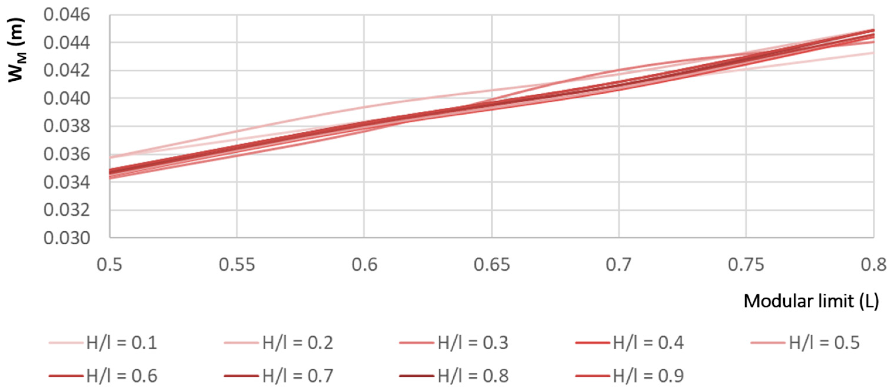
The joint effects of b
t, z
t, and p are presented in
Figure 7, where the relationship between the channel cross-section area for the maximum flow, w
M, and the modular limit for different values of H/l is shown when p = 0.012. The results show that it is better to study the effects of these variables independently since the size of the narrowed section increases as expected for a larger L, but there are no big differences when H/l varies with larger L values. Large differences were also not found when the value of p was varied.
3.2. Application Example
This example applies to the design of a long-throated flume located in the drainage channel of the rice plot using the methodology developed in this study.
The characteristics of this trapezoidal section earthen channel are as follows:
- –
Channel bottom width: bc = 0.4 m;
- –
Channel side slope: zc = 1.1798 (θ/2 = 49.71°);
- –
S (channel slope) = 0.002;
- –
n = 0.025 (Manning’s roughness coefficient);
- –
Channel depth: 0.89 m.
Flow rate range to be measured: Qm = 0.02 and QM = 0.05 m3/s
The input parameters for the design, adopted according to the channel characteristics, are as follows:
A high value is adopted for the modular limit since no great head losses are available in the channel. Thus, modular limit (L) = 0.7.
The sill height is set at the minimum value so that the height upstream of the flume is not too high and reaches the pipes draining from the plot to the canal. Thus, sill height (p) = 0.
The length of the throat is adopted by setting a value for the ratio H/l, which must be at least 0.5 to ensure uniform flow through the throat. A higher value implies higher head losses. Thus, ratio H/l = 0.5.
Applying the designed spreadsheet, the following throat section parameters are obtained:
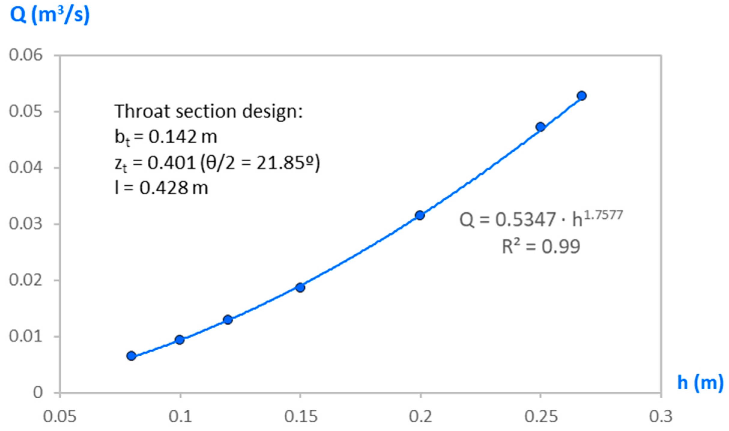
Throat bottom width, bt = 0.142 m
Side slope, zt = 0.401 (θ/2 = 21.85°)
Throat length: l = 0.428 m
The value of the threshold p should be increased if the bt value obtained is extremely small.
This design was checked using WinFlume software, and the results show that it meets all requirements, proving its validity; for this reason, it was adopted to design our long-throated flume (see
Table 2).
Since we did not have experimental data, this software was the best for calibrating and verifying the suitability of modular flume designs using other procedures, as shown by other authors (see references [
9,
11]).
Additionally, other authors calibrated their devices using experimental data from the literature (e.g., [
18]); however, we do not believe that this is the best solution.
3.3. Flow Rate Equation
To facilitate its use, the flow rate equation can be approximated by a potential relationship of the type (3c):
whose coefficients, c and n, are obtained by adjusting this relationship to the ordered pairs (h, Q) obtained either experimentally or analytically.
In this way, the flow rate, Q, is obtained directly from the upstream gaged head, h, and the iterative calculation of the flow rate in Equation (3b) is avoided.
This equation is only valid for each joint channel-long-throated flume geometry. In the case of the application example developed in
Section 4, we obtain the following flow rate:
4. Conclusions
A new analytical design of a long-throated flume interposed in a channel was proposed based on a range of measured flow rates and on the channel characteristics. This method allows us to directly calculate the dimensions of the narrowed section, side slope, and bottom width.
An example was used to demonstrate the accuracy of the developed method where the throat section is trapezoidal; however, the analytical procedure is the same for any geometrical shape of the narrowed section.
All the results obtained after generating multiple throat cross-sections demonstrate the reliability of the method used. Each user can choose the modular limit, as well as the sill height and the throat length most suited to the characteristics of the channel where the flume is to be installed, and the designed method will automatically provide them with the dimensions of the throat cross-section.
The design results were successfully evaluated using the WinFlume software. The consistency of the results obtained demonstrates the accuracy and feasibility of the procedure presented for designing the throat section of a long-throated flume.
The whole process was implemented in an Excel spreadsheet, allowing us to modify the input data and quickly check the accuracy of the results obtained.
A simplified discharge equation was implemented to facilitate flow rate calculation.
In conclusion, an original methodology that allows the automated design of a long-narrowing modular flume has been developed and successfully tested.


