Article

Experimental Study on the Effectiveness of Grouting in Controlling Breaching of High-Permeability Landslide Dams of Granular Materials

1
College of Water Resource and Hydropower, Sichuan University, Chengdu 610065, China
2
State Key Laboratory of Hydraulics and Mountain River Engineering, Sichuan University, Chengdu 610065, China
*
Author to whom correspondence should be addressed.
Water 2025, 17(22), 3310; https://doi.org/10.3390/w17223310
Submission received: 27 October 2025 / Revised: 13 November 2025 / Accepted: 17 November 2025 / Published: 19 November 2025
(This article belongs to the Section Hydraulics and Hydrodynamics)

Abstract

The barrier lake formed by the high-speed landslide that blocks the river typically faces a high risk of failure due to its loose and fragmented structure, high permeability, and weak erosion resistance. Based on the characteristics of this type of landslide dam, this paper proposes a new method for emergency rescue of barrier lake outburst by grouting inside the dam. Through 16 groups of experiments, the effects of three key parameters—grouting depth, grouting point arrangement, and layout position—on outburst control were systematically studied, and the mechanism by which grouting technology reduces outbursts was clarified. The results show that the inhibitory effect of the grouting consolidation body on particle initiation and transport, as well as the water-blocking effect caused by guiding water flow around, can fundamentally explain the good flood detention performance of grouting technology by reducing the flow section, limiting breach widening, and narrowing water flow. The depth and position of grouting are key factors for the peak clipping effect. The grouting point should be accurately positioned in the key area subjected to water flow erosion (on the breach side), allowing for a more effective blocking effect with fewer grouting points. When the grouting points are concentrated on the breach side, there is an optimal threshold for the number of grouting points, and benefits diminish after this limit is exceeded. The results can be used for emergency rescue and engineering measures related to the landslide dam.

1. Introduction

A barrier lake is a geological disaster formed when earthquakes, heavy rainfall, or other events induce collapses, landslides, or mudflows that block a river [1,2,3]. Its natural dam body is extremely unstable. When they breach, they release large amounts of water and soil in a short time [4,5], triggering destructive floods or debris flows, which pose a serious threat to the safety of people’s lives, property, and infrastructure downstream [6,7,8,9,10]. The Currence, type, and frequency of landslides in an area depend on both triggering events and predisposing conditions. Key natural factors influencing these include the local and regional topography and rock composition, the presence and distribution of geological weaknesses such as bedding planes, faults, joints, and cleavage systems, the type and depth of soil, the coverage and density of vegetation, and the mechanical and water-related properties of rocks and soils [11,12]. Among them, high-speed landslide-induced barrier lakes are particularly hazardous and challenging to mitigate. These dams typically originate from rock-type landslides. The process of rock collision and fragmentation occurs not only on the slope but also frequently extends to the riverbed and the opposite slope [13,14]. Consequently, a deposit with mixed material composition—including large rocks and gravel—forms on the opposite side of the valley. This deposit is characterized by a wide gradation range and a loose structure [15]. These unique material and structural characteristics result in high overall permeability and well-developed pores. Water seepage through the debris layer can easily induce internal erosion (piping) and collapse [16]. Furthermore, the dam’s weak scour resistance and the high erodibility of the fragmented rock make it particularly susceptible to water scouring [17].
Numerous scholars have pointed out that most barrier lakes will collapse in a short period of time based on historical data [18,19], triggering enormous outburst floods. Landslide dam outburst floods occur worldwide [20]. For example, the Hongshiyan barrier lake collapsed only 5 days after its formation [21,22]. The Baige barrier lake collapsed naturally and began to overflow on the third day of its formation [23,24], which highlights the extremely limited time window for emergency disposal of the barriers. It is especially critical and urgent to take effective engineering measures.
For typical barrier lake emergencies, the primary conventional mitigation measure is the excavation of a drainage channel. The Tangjiashan, Baige, and Yigong barrier lakes are typical cases where risk was reduced through manually excavated channels [25,26,27]. In recent years, several laboratory and field studies were conducted to investigate the overtopping-induced breach mechanism for landslide dams [28]; Concurrently, many scholars have also conducted a series of research studies on the emergency disposal technology of barrier lakes. Zhou et al. [29] and Shi et al. [30] proposed that compared with the common trapezoidal cross-section channel, a composite cross-section channel can significantly reduce the overflow height on the dam body, enhance the water discharge efficiency during the initial breach phase, and reduce the flood peak. Wang et al. [31] suggested that driving structural piles into the dam body during construction can be employed to retard the dam breach process. Chen et al. [32,33] proposed that throwing artificial structures in the drainage channel during the late drainage stage is an effective breach-reduction measure, as it can control the outburst flood discharge to remain within the protective capacity of downstream areas. Ruan et al. [34] introduced a flow control method based on FPN (flexible protective net) for dam break, which can intervene in the whole process of dam break under the premise of ensuring construction safety. However, these measures face significant challenges when applied to landslide dams: the loose structure and wide-graded dam materials make excavating stable drainage channels difficult and prone to rapid scour failure. Furthermore, the boulder-rich geological conditions impede the safe and efficient construction of structures like structural piles. Consequently, research on efficient emergency mitigation measures specifically tailored to this type of dam remains relatively limited.
Based on the characteristics of landslide dams with heterogeneous composition, well-developed pore structure and high permeability, this study proposes a new grouting-based mitigation method to reduce breach risks. As pointed out by Duan et al. [35], the bonding strength of materials is a key factor in resisting hydraulic erosion. This study aims to enhance the bonding strength of dam body materials through grouting measures, with the goal of suppressing particle migration caused by dam-break flows. The technique involves injecting grout into the dam, where it penetrates through highly permeable pores, cementing the fine-grained matrix and enveloping large stones. This process forms columnar consolidated bodies similar to solid piles, which enhance the structural integrity of the dam and helps to reduce and delay the flood peak, thereby mitigating the destructive impact of dam failure, and striving for response time for disaster prevention and mitigation in downstream areas.
In contrast to conventional piling techniques, which often rely on heavy machinery and are constrained by topographic complexity, the presented grouting approach offers superior operational flexibility and terrain adaptability. Its potential for rapid deployment makes it particularly suitable for time-sensitive emergency scenarios involving landslide dams with high breach hazards. Moreover, owing to the straightforward implementation process and enhanced operational safety associated with internal grouting, this technique demonstrates considerable promise for practical engineering applications, especially in remote or inaccessible regions where conventional methods are logistically infeasible. Accordingly, flume experiments were conducted to investigate the effects of three key factors: grouting depth, layout pattern, and arrangement of grouting points. The study focuses on how internal grouting influences peak flood reduction, breach development control, residual dam height, and overall stability. The mechanisms behind these effects are also analyzed. The findings of this study can offer important scientific support for emergency response to debris-flow landslide barrier lakes.

2. Experimental Methods

2.1. Experimental Setup

The model tests were carried out in a custom-designed flume. The flume comprises four main components: a water supply equipment, a right-angle triangle weir ( l   ×   w   ×   h   =   1 . 5   m   ×   1 . 0   m   ×   1 . 0   m ) , a main flume ( l   ×   w   ×   h   =   6 .25 m × 0.4 m × 0.3 m), and a tail water pool ( l   ×   w   ×   h   =   1 .0 m × 1.0 m × 0.5 m), as shown in Figure 1a. These components are used to stabilize inflow, simulate the dam-break process, and collect waste.

2.2. Model Dam

This study employed the Yaozigou landslide dam as the prototype for designing the dam dimensions and material gradation. The Yaozigou barrier lake formed when a massive landslide triggered by the “5.12” Wenchuan Earthquake, the sliding rock mass fragmented through tumbling and collision, ultimately accumulating on the bedrock slope of the left bank and blocking the river channel. The prototype dam had an average height of approximately 50 m, a width of about 80 m, and a length along the river direction of approximately 200 m. The upstream dam slope Su was approximately 45°, and the downstream dam slope Sd was approximately 35°.
Considering the experimental site, flume dimensions, testing equipment, and model dam material properties, a scaled experiment was designed. A geometrically scaled model of the landslide dam at a scale ratio of 1:200 was utilized in all test conditions. The model dam cross-section was rectangular, with the dam length equal to the flume width of 0.4 m (Figure 1c). While natural landslide dams are typically irregular in shape due to their formation mechanism, their longitudinal profiles are often approximated as trapezoidal [36,37]. Accordingly, a simple trapezoidal profile was adopted for the model dam’s longitudinal section (Figure 1b). Thus, the model dam had a height of 25 cm, a crest width of 40 cm, and a base width of 100 cm. The dam slopes were maintained identically to the prototype. The model dam was positioned in the middle-upper section of the rectangular flume, with the upstream slope toe located 1.2 m from the flume inlet.
Geometric scaling laws must be satisfied in designing physical model tests to ensure that the model dam is able to represent natural landslide dams. Therefore, three key dimensionless geometric parameters characterizing landslide dams were introduced: H/B, V d 1 / 3 /H, V l 1 / 3 /H [38], as shown in Table 1. The height-to-width ratio reflects the erosion slope by controlling the flow velocity and erosion rate; the dam morphology coefficient indicates the amount of dam material and influences the breaching calendar time and outflow; the barrier lake morphology coefficient characterizes the potential upstream inflow and the scale of dam breaching [39]. The values of these three dimensionless parameters set for the experiments fell within the reasonable ranges established based on a well-established database encompassing 80 landslide dam cases [40]. This validates that the model dam used in this study effectively simulates a large, realistic natural landslide dam.

2.3. Experimental Materials

Landslide dams generally consist of materials with broader grain size distributions than artificial dams and river embankments [41,42,43]. The Yaozigou barrier lake dam consists primarily of angular blocks and driftstone of diorite from the Chenggang to Jinnings period. The model dam material was scaled from the average particle size distribution curve of the Yaozigou landslide dam at a geometric scale of 1:200 (Figure 1d). The maximum particle size used was less than 25 mm, which is significantly smaller than the flume width (400 mm), thereby eliminating sidewall effects.

2.4. Experimental Data Processing

The experimental process, encompassing dam state evolution, breach development, and water level variations, was recorded by four strategically positioned cameras as illustrated in Figure 1a. Camera #2 was installed above the dam crest and utilized in conjunction with a precision steel ruler (minimum graduation = 1 mm) to measure the breach crest width and breach base width, where the breach base width was equated to the breach flow width [44]. Transparent grid overlays (individual cell size = 2 cm) were affixed to the side glass panels of the flume, and Camera #3 was mounted laterally to record the longitudinal evolution of the dam body, as well as breach depth progression and water depth fluctuations. Camera #1 was positioned at the downstream end of the flume to document the condition of the downstream dam slope, lateral collapses, and the observed breach morphology in the downstream region. Finally, Camera #4 was installed adjacent to the impounded lake to record upstream water level changes in conjunction with water level measurement.
The breach outflow Qout was calculated based on the upstream water level. Using the real-time upstream water level recorded by Camera #4, the storage volume of the barrier lake Vl at different times was determined. Then, the water balance equation of the barrier lake is applied to calculate the breaching flow Qout:
Q i n Q o u t = d V l d t
where Qin is the inflow rate, Qout is the breach outflow rate, Vl is the storage volume of the barrier lake, and t is time.
The residual morphology of the dam body was scanned using a SCANTECH handheld 3D laser scanner to obtain its point cloud distribution and then processed and analyzed.

2.5. Experimental Conditions

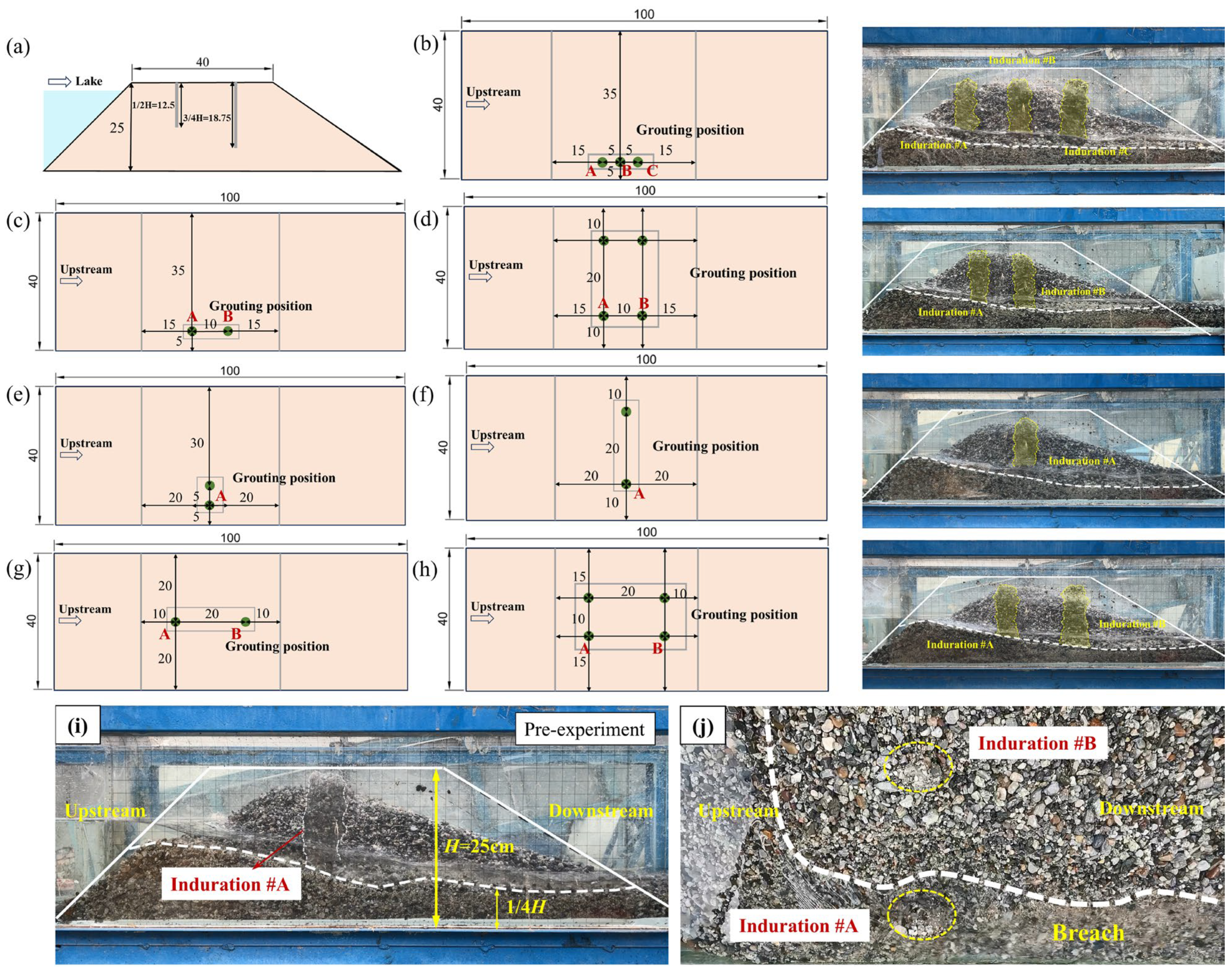
Pre-experiment (Figure 2i) indicated that the protective armor layer formed after dam breach had a thickness of approximately 0.25H. This observation implied that grouting depths beyond 0.75H would yield diminishing returns for breach control. Therefore, two grouting depth levels were selected for the formal test matrix: 0.5H (Groups A and B) and 0.75H (Groups C and D). Simultaneously, preliminary observations (Figure 2j) showed that consolidated grout bodies formed by grout points placed distal to the breach flank (Position B) remained inactive during the breach process. To investigate the potential breach control efficacy of grouting at this location, two distinct grout point placement strategies were implemented: uniform distribution within the dam body (Groups A and C) and concentrated placement proximal to the breach flank (Groups B and D). Furthermore, five grout point arrangement patterns were designed for each test group: 1 × 2, 2 × 1, 2 × 2-lateral, 2 × 2-longitudinal, and 3 × 1 arrays (where a × b denotes the array dimensions, with a representing the number of rows and b the number of columns). Finally, the inflow rate (Qin) for all tests was set to 1.35 L/s to satisfy the Froude similarity criterion. To quantitatively analyze the hazard mitigation effectiveness of the different configurations, a total of 16 tests were conducted, maintaining identical particle size distribution and total mass for the dam material across all tests. Schematic diagrams of the grout point layouts are presented in Figure 2, and detailed test condition parameters are provided in Table 2.

3. Experimental Results

3.1. Typical Failure Process of Landslide Dam

Experimental results demonstrate that after the grouting treatment inside the landslide dam, the breaching process could be divided into the overflow erosion stage (Stage I), the breach development stage (Stage II), and the decay equilibrium stage (Stage III). The breach process was significantly suppressed, with the peak discharge occurring during Stage II, consistent with findings from previous studies [45,46]. The breach process of the grout-treated landslide dam is analyzed in detail using Test A-1 as an exemplar case.
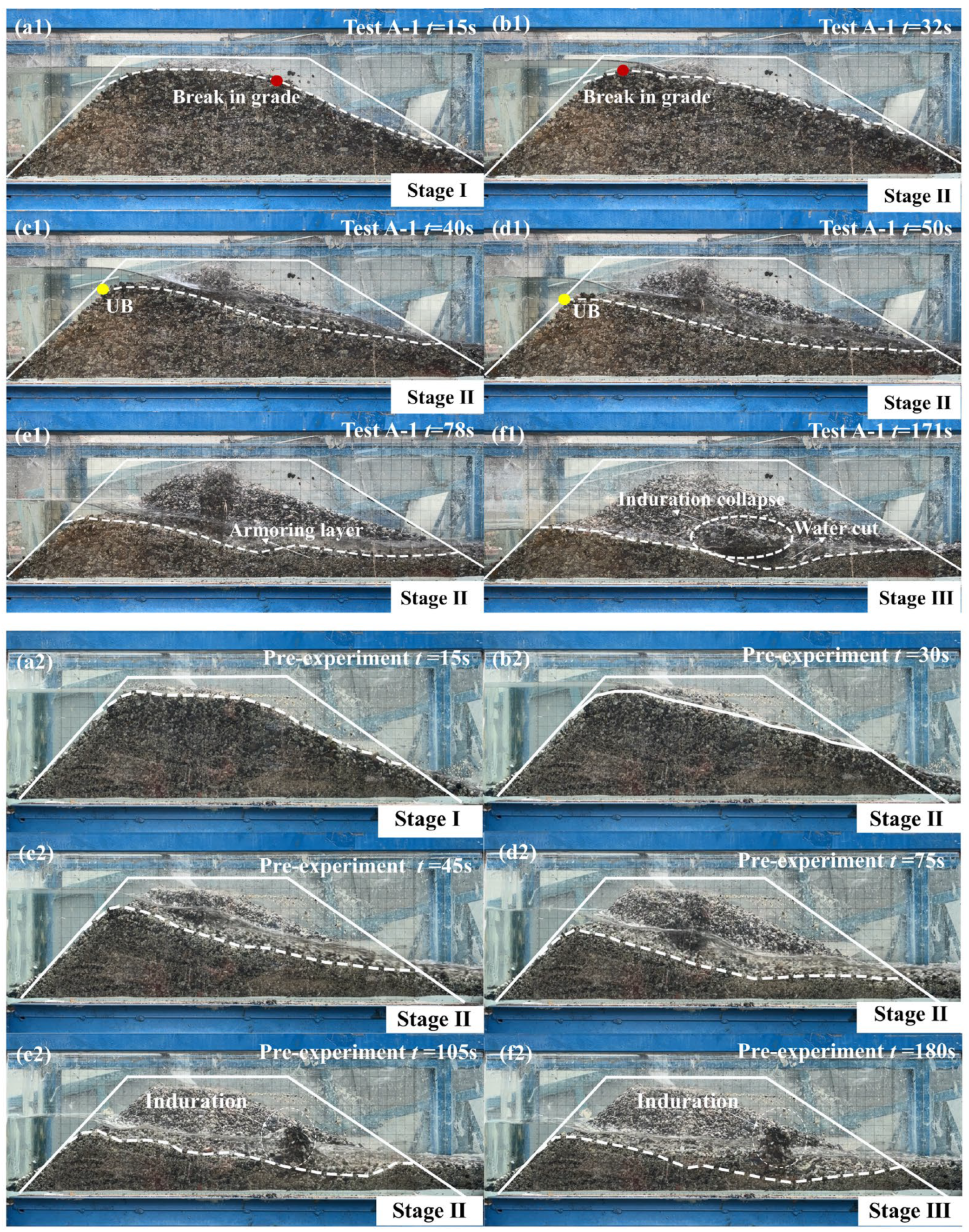
The breach evolution for Test A-1 is chronologically depicted in Figure 3(a1–f1), with the initial breach time (t0 = 0 s) defined as the moment when overtopping flow fully traversed the breach crest and reached the downstream toe. The loose, granular nature of the dam material prompted initial seepage-induced slumping, which flattened both the upstream and downstream slopes. During Stage I, erosion initiated on the downstream slope face, and the slope inflection point on the dam’s longitudinal profile progressively migrated upstream. By t = 32 s, the inflection point approached the upstream slope face (Figure 3(b1)), marking the completion of a full cycle of headward erosion. The breach subsequently entered Stage II, where the longitudinal profile evolved into a triangular cross-section. Erosion commenced at the upstream breach point (denoted UB), accompanied by a rapid increase in breach discharge and depth, reaching the peak discharge of 2.598 L/s at t = 60 s. Concurrently, the consolidated grout bodies formed within the treated dam became progressively exposed. As point UB descended continuously until t = 171 s, erosion ceased at the breach head, signifying the transition to Stage III. During this stage, flow velocity decreased significantly and sediment transport capacity diminished sharply, resulting in selective entrainment and downstream transport of finer particles, while coarser particles deposited on the breach bed, forming a protective armor layer. This layer effectively shielded the underlying material from further erosion, ultimately halting breach expansion. Consequently, the residual dam morphology stabilized, and an upstream-downstream flow equilibrium was established, concluding the breach process.
The breach process for the pre-experiment is illustrated in Figure 3(a2–f2). During Stage II, a substantial release of reservoir water occurred upstream at t = 105 s, triggering rapid breach downcutting. This led to the scour and entrainment of particles at the base of the consolidated grout body, followed by its loosening and subsequent separation from the non-consolidated dam material. The loosened mass then collapsed and tumbled downstream of the breach (Figure 3(e2,f2)), which impacting and disrupting the pre-existing armor layer at the breach bottom and gradually forming a scour hole around the remaining grout body. To assess whether the loosening phenomenon of the grout body during breaching was stochastic, a replicate experiment under identical conditions was conducted for Test A-1. The results confirmed that the complete loosening and collapse of the grout body into the breach (Figure 3(f1)) recurred, and the characteristics of the breach process exhibited high consistency.

3.2. Evolution of Flow Discharge

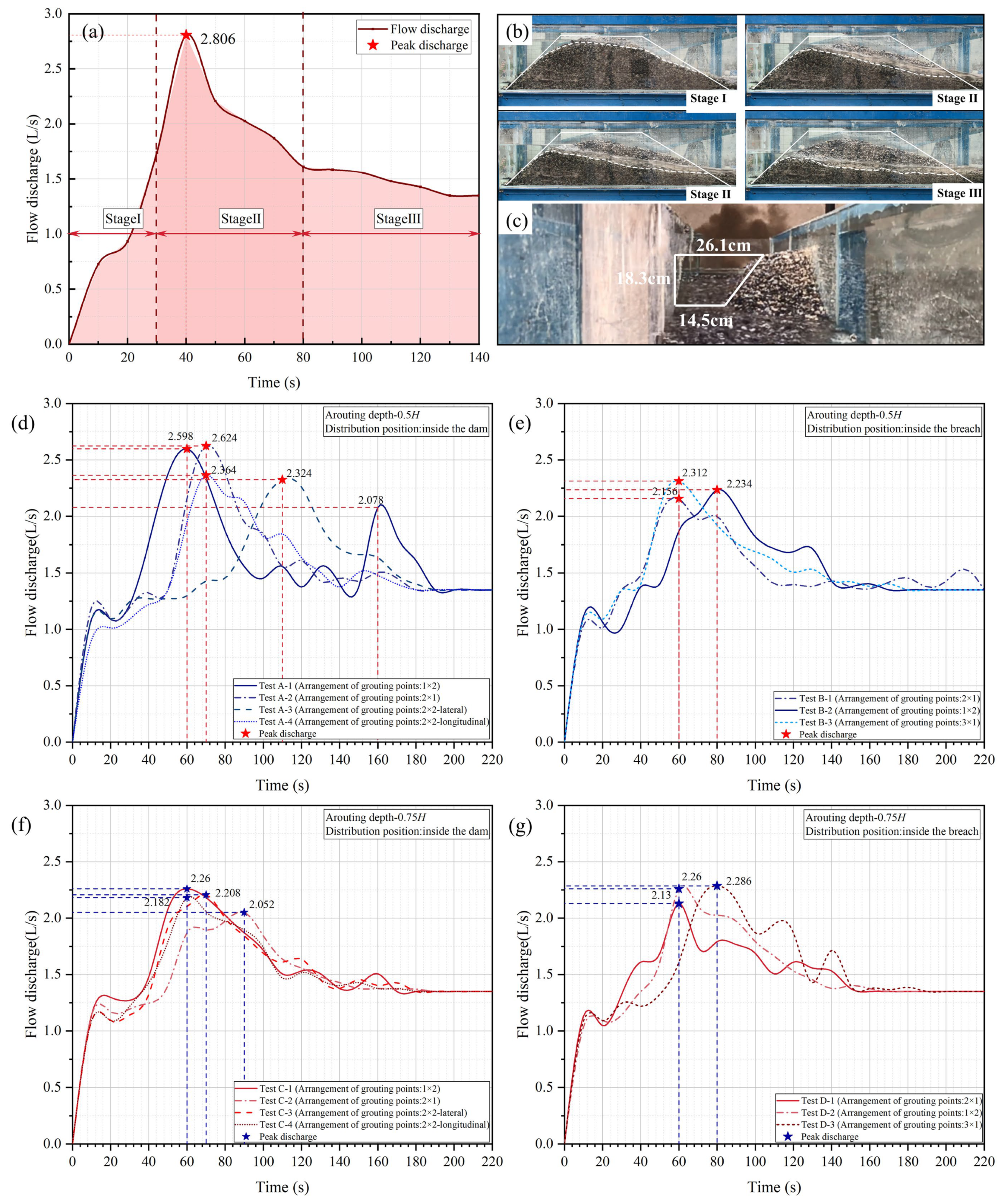
Breach discharge serves as a critical parameter characterizing erosion intensity and stage evolution. As depicted in Figure 4, compared to the peak discharge of 2.806 L/s observed in the blank test (Figure 4a), all four experimental groups (A, B, C, D) achieved effective peak discharge reduction, albeit to varying degrees. The breach discharge curves for Group A (grouting depth = 0.5H, uniformly distributed grout points) are shown in Figure 4d, exhibiting peak discharge reductions of 7.41%, 6.49%, 17.18%, and 15.75%, respectively. Notably, the peak reduction rates for multi-row/column configurations (Test A-3, Test A-4) were approximately double those of single-row configurations (Test A-1, Test A-2). This indicates that increasing the number of grout points proximal to the breach flank through varied arrangement patterns proportionally enhances peak discharge reduction. Furthermore, the discharge curve for Test A-1 displayed a distinct “bimodal peak” characteristic. This resulted from the toppling of a grout body near the breach flank, which temporarily obstructed the flow and trapped coarse particles. The subsequent breaching of this obstruction restored flow, generating the secondary peak.
For a grouting depth of 0.75H with uniform point distribution (Group C, Figure 4f), the peak discharge was reduced by 19.46% to 26.87% across the different arrangements. This represents a substantial enhancement in peak discharge reduction efficacy compared to the shallower grouting depth of 0.5H (Group A).
For Group B (grouting depth = 0.5H, points concentrated near the breach flank, Figure 4e), peak discharges decreased by 23.16%, 20.38%, and 17.61%. Contrasting with Group A at the same grouting depth, concentrating grout points near the breach flank instead of uniform distribution enabled Tests B-1 and B-2 to achieve superior peak reduction to Tests A-3 and A-4, despite utilizing fewer grout points.
Group D (grouting depth = 0.75H, points concentrated near the breach flank, Figure 4g) yielded peak discharge reductions of 24.09%, 19.46%, and 18.53%. Compared to Group B (same point concentration, depth = 0.5H), increasing the grouting depth to 0.75H did not yield a substantial improvement in peak reduction. Furthermore, under identical grouting depth and point placement (concentrated near breach flank), altering the arrangement pattern (e.g., Test B-3 vs. Test B-1; Test D-3 vs. Test D-1) exerted negligible influence on peak discharge reduction. This demonstrates that when grout points are concentrated near the breach flank, modifying the spatial arrangement pattern has minimal impact on peak attenuation effectiveness.
The synthesis of data presented in Figure 4 demonstrates that the effectiveness of peak flow attenuation is influenced by grouting depth, arrangement pattern, and distribution location. Moreover, in all grouted cases, the peak discharge occurred between 60 and 80 s, representing a delay of 20 to 40 s compared to the peak time of 40 s in the blank test. These results confirm that the grouting treatment effectively retards the breach flood peak, significantly delaying its arrival. Notably, Tests A-3 and C-2 exhibited particularly pronounced delays, with peak occurrence times reaching t = 110 s and t = 90 s, respectively. These correspond to delays of 70 s and 50 s relative the blank test. Furthermore, the total breach duration for all grouted cases was approximately 180 s, representing an extension of approximately 40 s compared to the 140 s duration observed in the blank test.

3.3. Morphological Evolution of the Breach

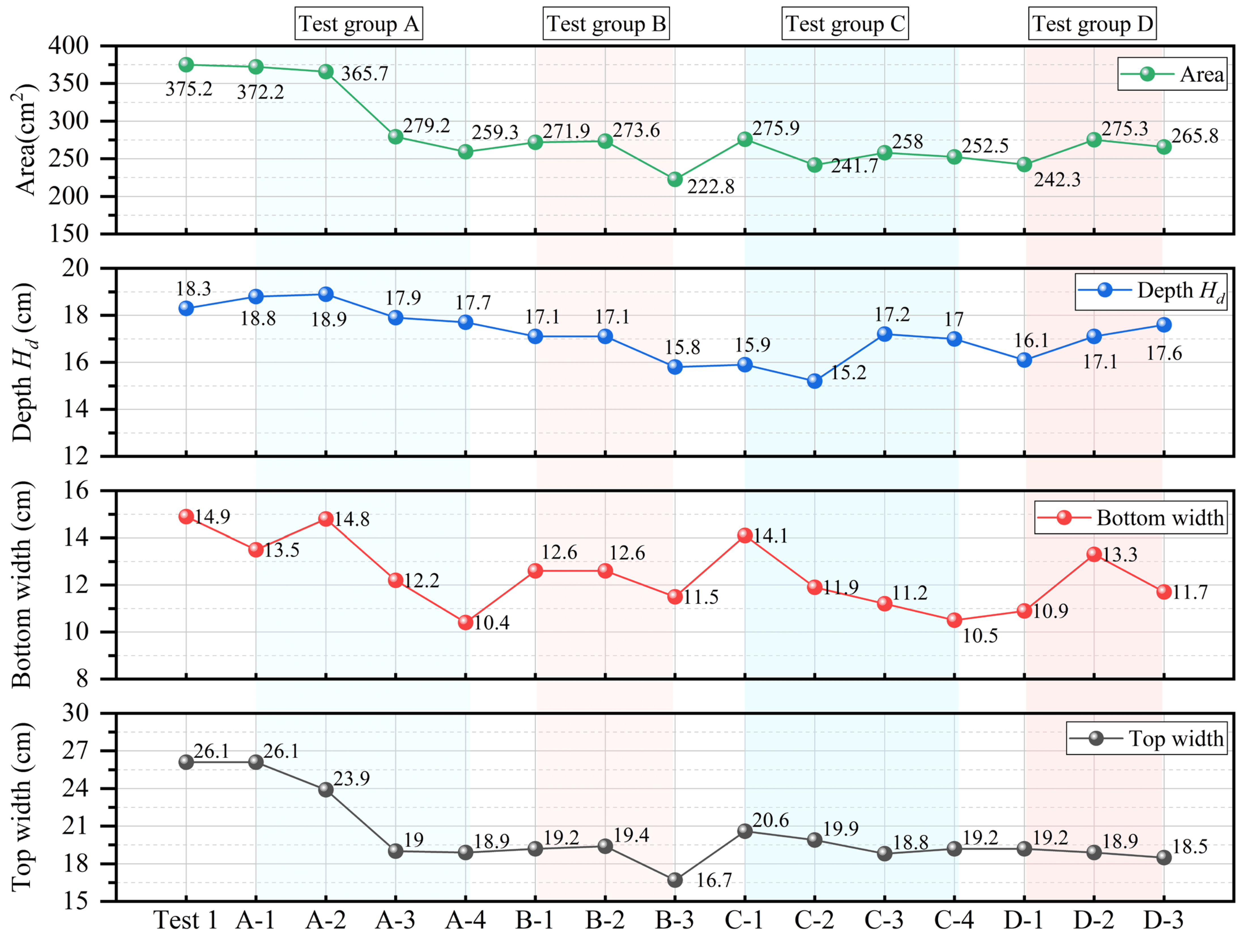
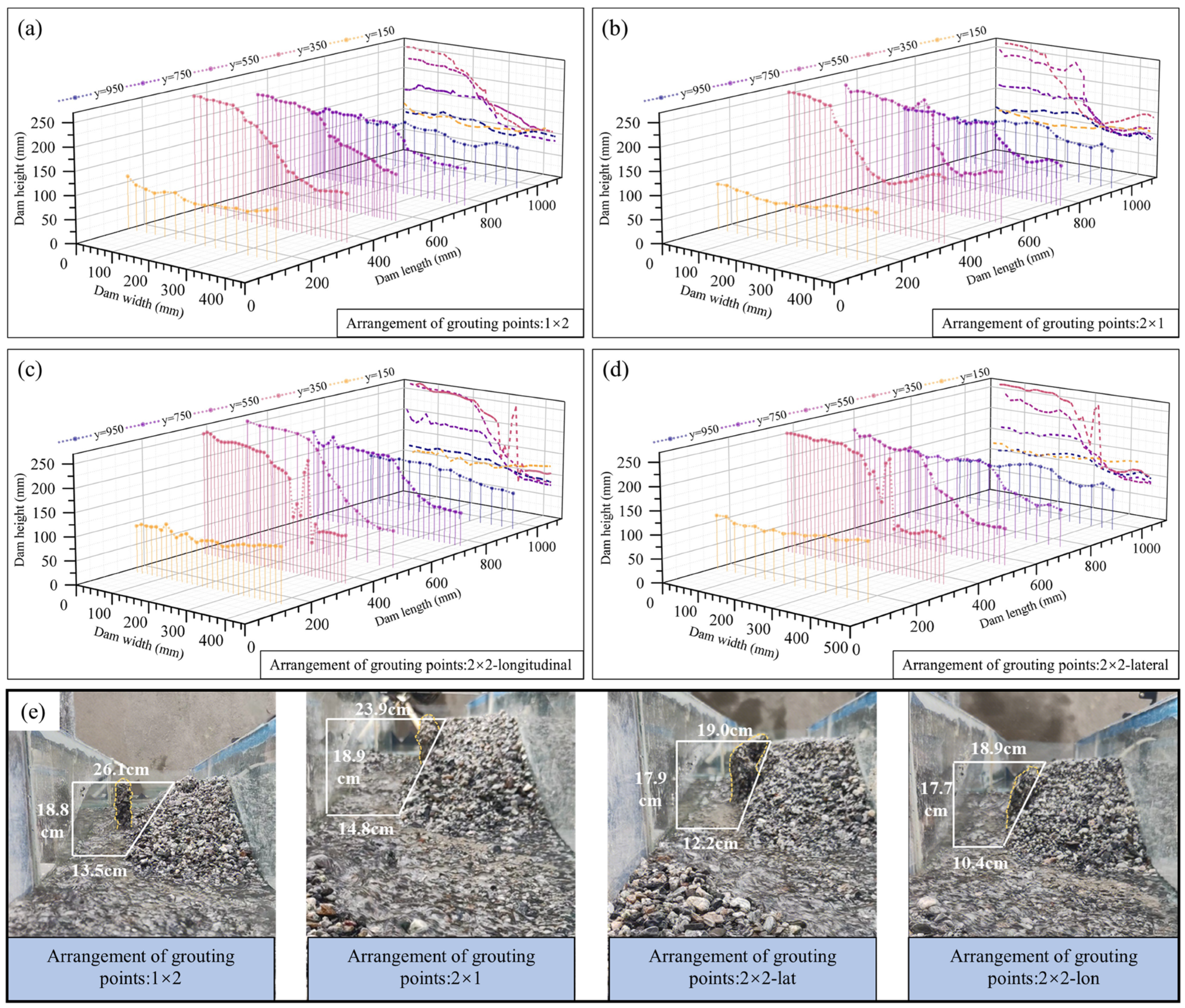
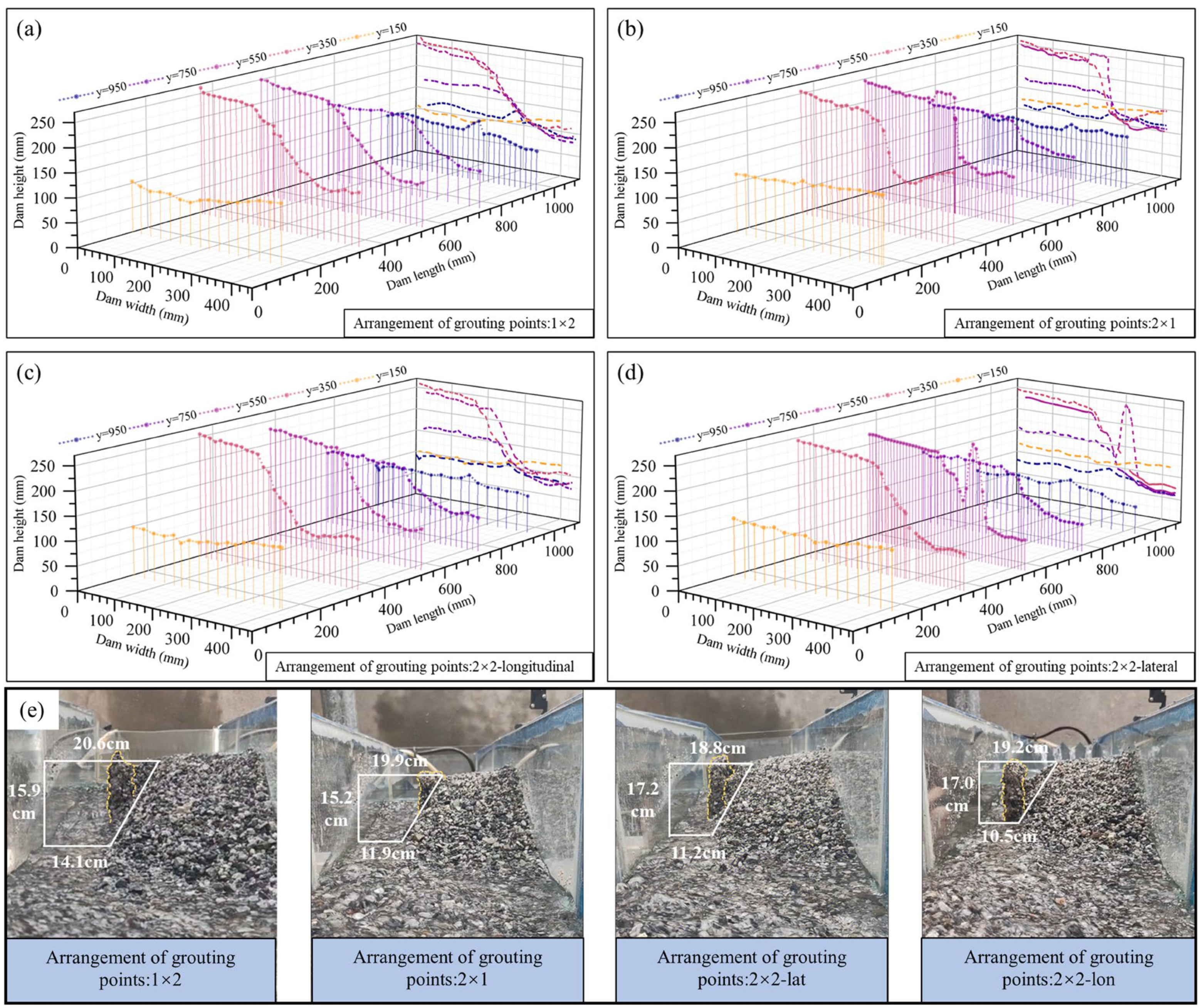
The final breach dimensions (top width, base width, depth, and area) for all tests are presented in Figure 5. Experimental results indicate that compared to the control group (375.2 cm2), the final breach area was significantly reduced in all tests except A-1 and A-2, with reductions ranging from 25.59% to 40.62%. Simultaneously, the widening of the breach top, base, and the downcutting of its depth were restrained to varying degrees. This indicates that the consolidated grout bodies effectively restricted vertical erosion of the breach, thereby reducing breach depth and suppressing lateral expansion. Collectively, these mechanisms diminished the cross-sectional flow area, thus controlling the landslide dam breach process. Analysis of the final breach morphology in Group A (Figure 6) highlights a clear distinction. Under identical grouting depth and distribution, Tests A-3 and A-4 yielded final breach areas of 279.2 cm2 and 259.3 cm2, respectively. These areas are significantly smaller than those in Tests A-1 and A-2 (372.2 cm2 and 365.7 cm2). This indicates that the key factor enhancing breach control effectiveness is the number of grouting points positioned near the breach side. Consolidation bodies located farther from the breach side primarily serve to enhance dam stability during breaching, with their influence on reducing breach scale being negligible.
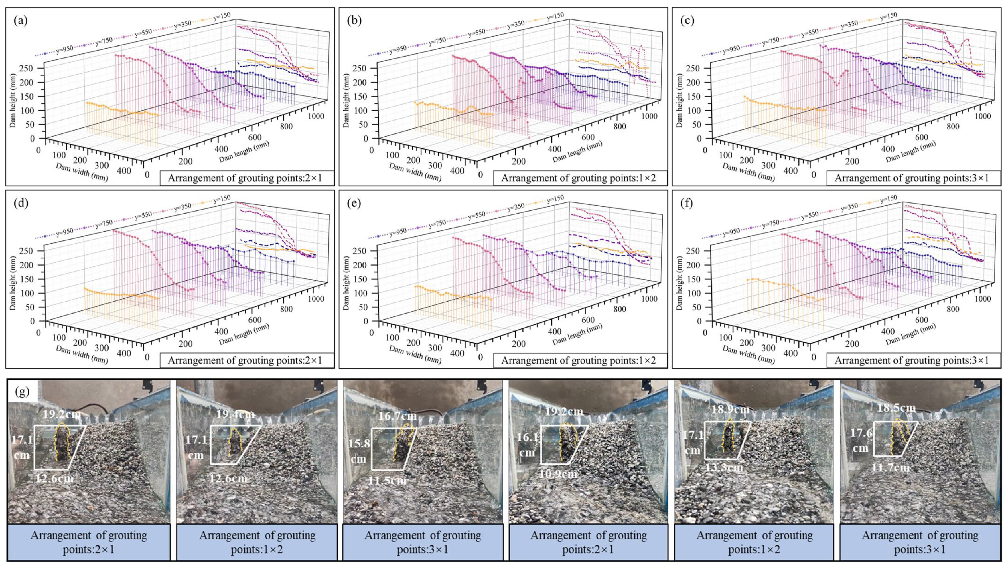
Furthermore, according to Figure 7, after increasing the grouting depth to 0.75H, the final breach areas for Tests C-1 to C-4 all decreased substantially, with reductions ranging from 26.47% to 35.58%. However, the final breach areas for Tests C-3 and C-4 (Figure 7c,d) are measuring 258 cm2 and 252.5 cm2. Respectively, did not exhibit a significant decrease compared to those for Tests C-1 and C-2 (Figure 7a,b), which were 275.9 cm2 and 241.7 cm2. This demonstrates that after optimizing the grouting depth, increasing the number of grouting points near the breach side provides limited additional improvement in breach reduction effectiveness; a synergistic effect was not achieved. This conclusion is consistent with the aforementioned breach flow analysis results. The final breach profile morphology and downstream view projection shapes of Test B-1 to B-3 and D-1 to D-3 are shown in Figure 8.
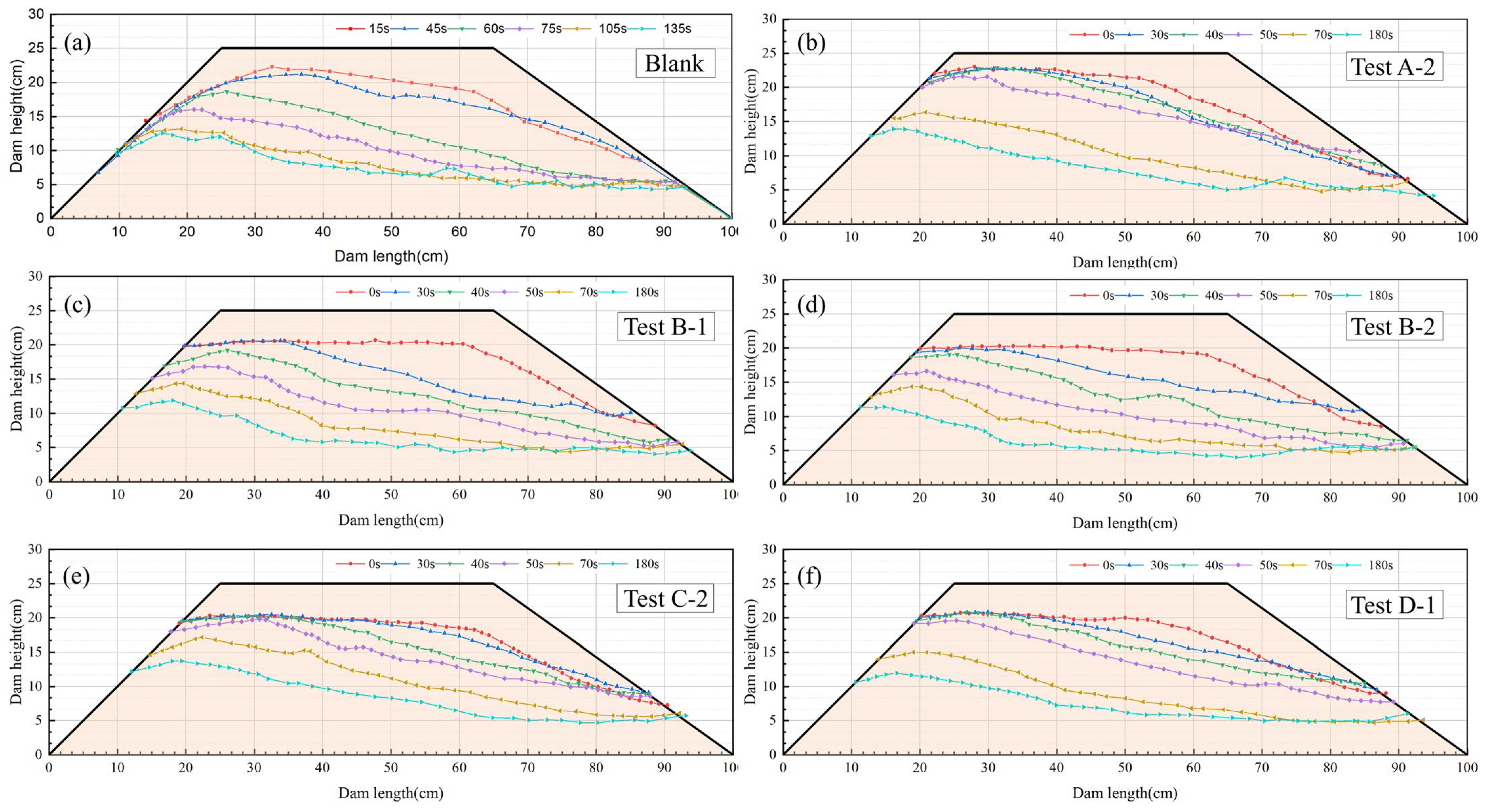
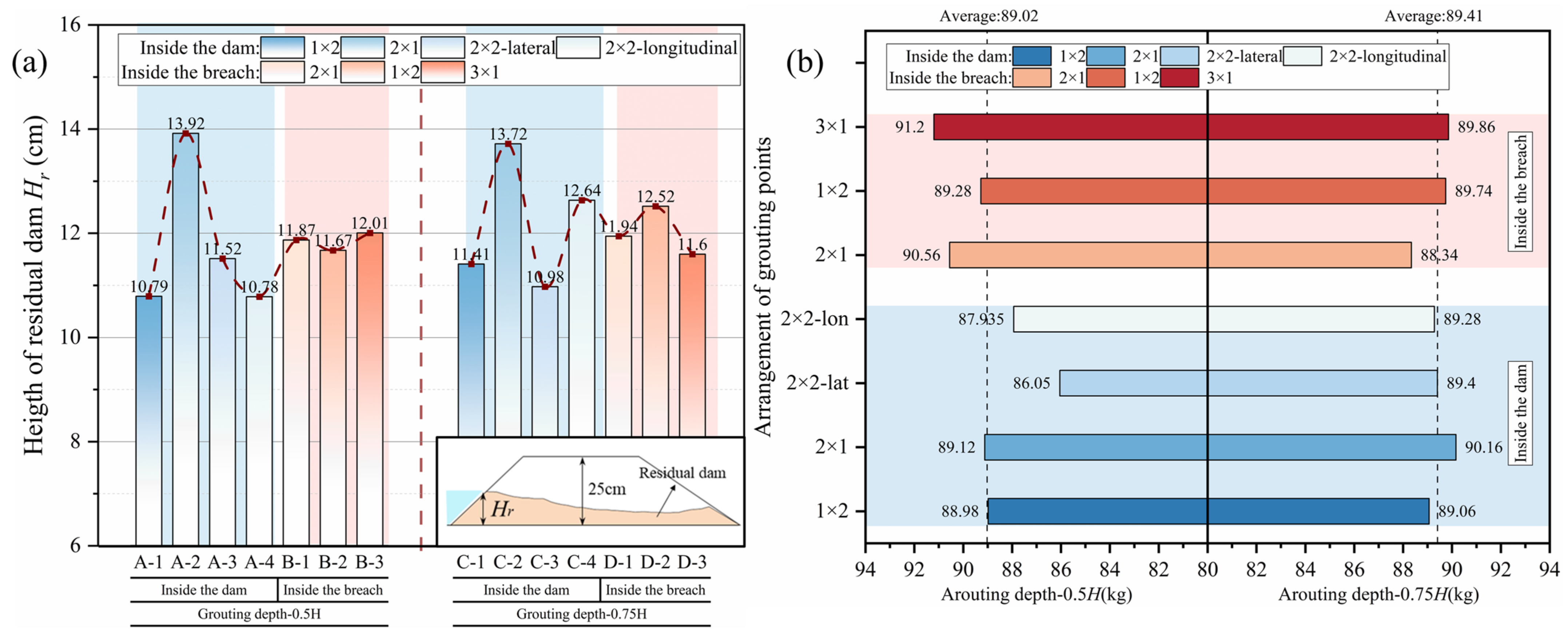
Taking The blank test, TestA-2, TestB-1, TestB-2, TestC-2, and TestD-1 as examples, the longitudinal morphological evolution of the dam body, as shown in Figure 9, was obtained through image digitalization processing based on captured images of the breach process (e.g., Figure 3) recorded at six time points: t = 0 s, 30 s, 40 s, 50 s, 70 s, and 180 s. As shown in the figure, the blank group (Figure 3(a1,a2) experienced rapid downward cutting during the time period of t = 45~60 s, while TestA-2 and TestD-1 experienced a certain lag effect during t = 50~70 s. The downward cutting speed of the landslide dam in the other three working conditions was relatively slow and tended to be uniform throughout the entire collapse process. At the same time, the blank group gradually stabilized after collapsing at t = 105 s, until the longitudinal evolution was not significant at t = 135 s, while the rest of the operating conditions only tended to stabilize at t = 180 s. In addition, during the collapse process of the blank group, the upstream dam body showed a significant slope, while after grouting, it was similar to a platform, indicating that the internal grouting of the landslide dam weakened the erosion of the upstream dam slope by the water flow of the collapse. Analysis indicates that grouting effectively restricted the downward erosion of the breach. Concurrently, significant differences in the morphology of the residual dam were observed (Figure 10a). Specifically, the post-failure residual dam heights for Test A-2 and Test C-2 were notably greater, measuring 13.92 cm and 13.72 cm, respectively. Compared to the maximum residual height of 12.57 cm observed in Test 1, this represents increases of 10.74% and 9.15%. This indicates that when employing a 2 × 1 arrangement with grouting points uniformly distributed within the dam body, a relatively high residual dam height can be maintained post-failure, even under varying grouting depths.

3.4. Residual Landslide Dam Morphology and Material Transport Characteristics

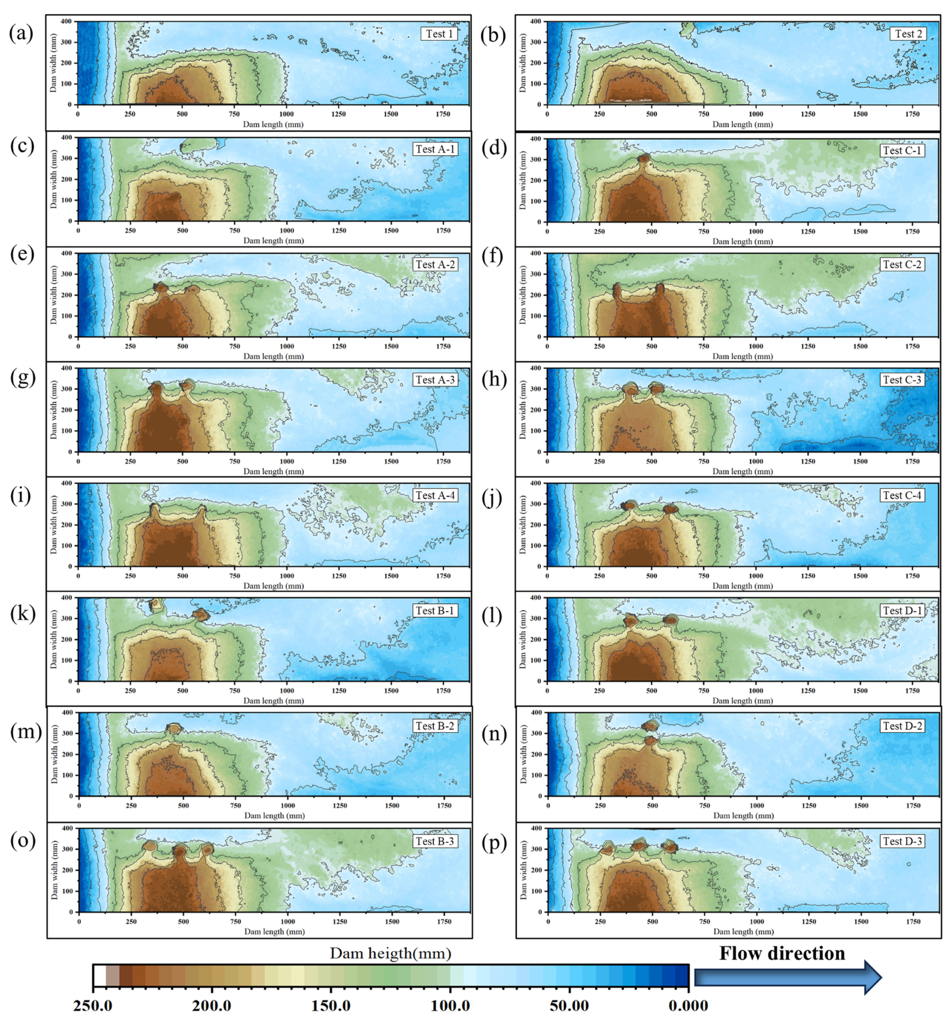
As shown in Figure 11, derived from three-dimensional scanned point cloud data, the grouting depth, arrangement pattern, and layout position significantly influence the morphology of the residual dam and channel evolution. Compared to the control group, the residual dam volume and height increased to varying degrees across different Tests, and the breach evolution process and sediment transport were effectively suppressed. This indicates that the consolidation bodies formed by internal grouting not only restrict the lateral expansion and vertical downcutting of the breach, thereby reducing the overall disaster intensity, but also intercept and anchor dam materials, diminishing the propagation range and impact severity of the disaster.
The total initial dam mass for each set of tests is 110 kg, and the residual dam mass for different tests is shown in Figure 10b. The residual masses of the four groups of tests are all larger than those of the control group, which indicates that different grouting forms can slow down the erosive transporting effect of the breaching current on the dam body. When the grouting points were uniformly distributed, the arrangement was 2 × 1, and the grouting depth was changed (Tests A-2 and C-2), the residual mass of the dam body peaked at 89.12 kg and 90.16 kg, respectively, which increased by 15.14% and 16.49% compared with the blank group, respectively. Similarly, when the grouting points were concentrated near the breach side, the residual masses of Tests B-3 and D-3 with a 3 × 1 arrangement were 91.20 kg and 89.74 kg, which were also the maximum values within the group, increasing by 17.83% and 15.94%, respectively, compared to the blank group, but compared to Tests B-1 and D-1 with a 2 × 1 arrangement, which had a residual mass of 90.56 kg and 88.34 kg, adding one grouting point did not increase the residual mass of the collapse substantially.
The post-test residual dam masses, averaged for each group, were 88.02 kg (A), 90.35 kg (B), 89.48 kg (C), and 89.31 kg (D). Notably, the overall mean residual mass for the deeper grouting depth (0.75H, Groups C and D) was 89.41 kg, slightly exceeding the 89.02 kg mean for the shallower depth (0.5H, Groups A and B). Comprehensive analysis indicates that schemes concentrating grouting points near the breach side outperform those with uniform distribution. Furthermore, increasing the grouting depth enhances the breach resistance stability of the dam body.

4. Discussion

The experimental results demonstrate that the internal dam grouting technique exhibits broad applicability for controlling landslide dam (or barrier lake) breaching. The consolidation bodies formed post-grouting manifest a triple mechanism during the breaching process: (1) Deflecting breach flow and providing flow resistance due to the presence of the consolidation bodies; (2) Restricting breach widening and constricting flow; (3) Impeding the initiation and transport of dam material particles. However, insufficient grouting depth (e.g., in the pre-experiment and A-1) renders the consolidation bodies susceptible to scouring, consequently failing to achieve significant peak flow attenuation.

4.1. Influence of Water-Blocking Effect on Breach Reduction

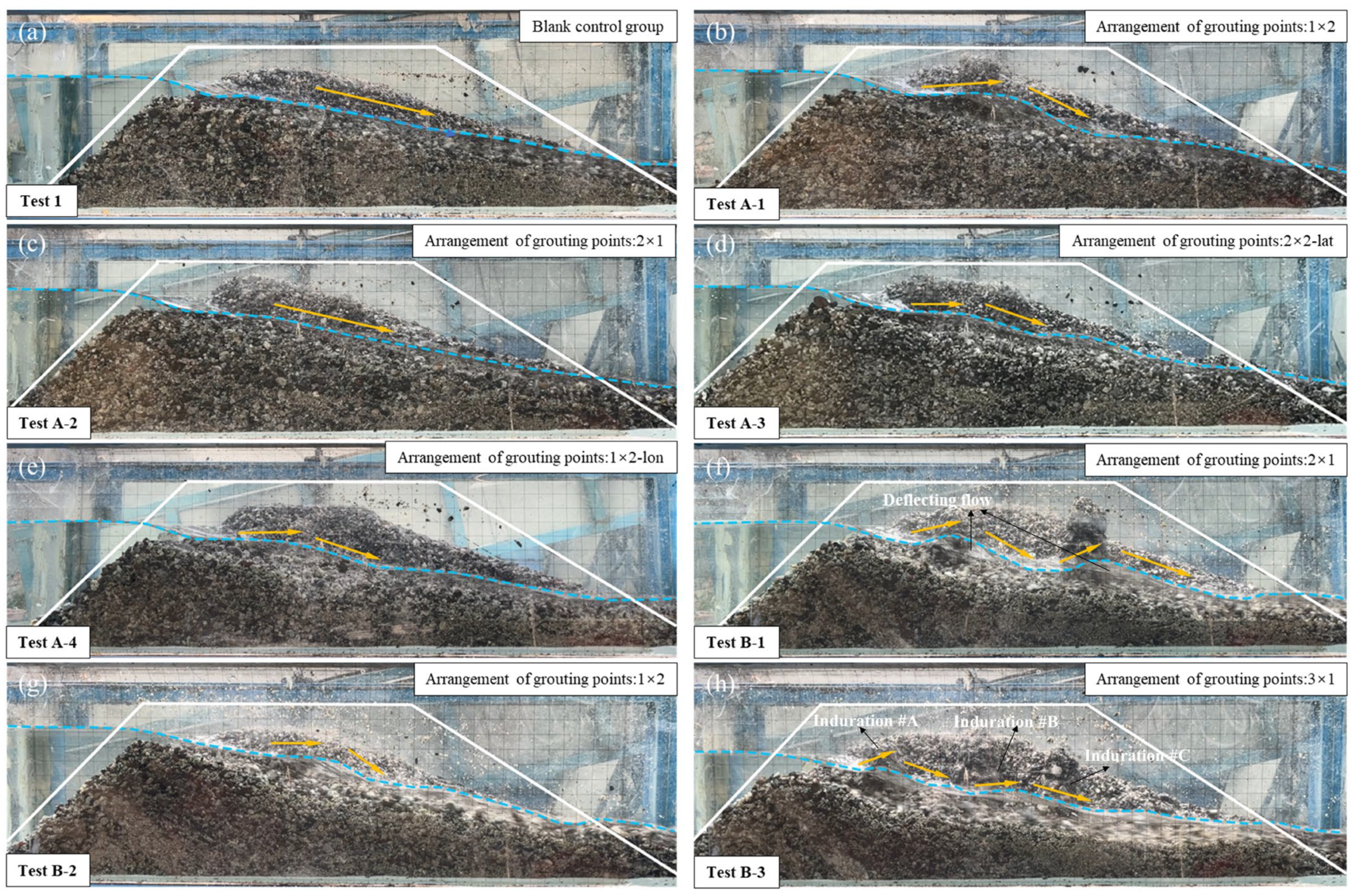
Figure 10 demonstrates that, compared to the control group (Figure 12a), the consolidation bodies formed by grouting significantly alter the breach flow regime. Positioned within the breach, these bodies increase the flow-resisting area, leading to a reduction in the effective flow cross-section and causing localized congestion upstream of the consolidation bodies. Their flow-resisting effect disrupts the initially smooth discharge flow, inducing water level backwater upstream of the bodies and forming a nearly platform-like water surface profile. Subsequently, the flow plunges near the downstream end (tail) of the consolidation bodies.
This flow regime is consistent with the velocity distribution patterns documented around bridge piers, which serve as a useful analogy for the consolidation bodies [47]. Specifically, the flow velocity decreases sharply upstream of the obstruction, nearly stagnating, and remains low in its immediate wake due to backwater effects. This pronounced reduction in flow velocity directly diminishes its erosive power and sediment transport capacity, thereby suppressing breach evolution and downstream sediment delivery.
A key observation from Test A-2 was that the consolidation bodies, positioned away from the primary flow path and nearer the sidewalls, functioned primarily to restrict lateral breach widening. Consequently, the resulting flow regime (Figure 12c) was virtually indistinguishable from that of the control group, as the characteristic flow-obstruction effect was absent. This resulted in a peak discharge of 2.624 L/s, representing only a 6.49% reduction compared to the blank test, yielding a relatively insignificant peak flow attenuation effect. This observation explains why concentrating grouting points near the breach side yields superior breach reduction effectiveness compared to uniform distribution within the dam body. Therefore, judicious selection of grouting parameters, including arrangement pattern and positioning, critically influences breach control effectiveness.

4.2. Influence of Bypass Flow on Breach Reduction

This flow diversion mechanism aligns with studies on bridge piers, which demonstrate that obstructions force flow deflection, accelerating it along the sides while creating low-velocity zones upstream and downstream [48]. In the context of a dam breach, the high-velocity flow deflected around a consolidation body impacts the downstream zone, where intense shear and frictional interaction can precipitate a hydraulic jump (Figure 12f). This jet subsequently collides with the downstream water body, generating particularly intense surface turbulence. This process dissipates considerable energy, significantly attenuating the breach peak discharge. This energy dissipation mechanism resembles the surface roller energy dissipation principle investigated by [49].

4.3. Influence of Grouting Parameters on the Effectiveness of Flow Control

Grouting depth predominantly governs the effectiveness of grouting in mitigating landslide dam breaching. When the depth increased from 0.5H (Group A) to 0.75H (Group C), although the percentage of the cross-sectional area occupied by the projection of a single consolidation body increased by only 2.5%, the peak flow attenuation rate (ΔQ/Q0) significantly improved from 6.49~17.18% to 19.46~26.87%. This indicates that increasing the grouting depth substantially enhances the scour resistance and interception capacity of the consolidation bodies, thereby improving peak flow attenuation.
The grouting location plays a pivotal role. For the same grouting depth, concentrating grouting points near the breach side (Group B) yielded significantly superior peak flow attenuation compared to uniform distribution (Group A). This confirms that focusing grouting points within the key erosion zone (breach side) more efficiently impedes breach development, achieving better results with fewer grouting points.
Furthermore, the number of grouting points and the arrangement pattern exhibit marginal effects with diminishing returns. When grouting points were concentrated near the breach side, increasing their number did not significantly enhance the attenuation rate. This reflects the existence of an optimal threshold for the number of grouting points under this configuration; exceeding this threshold yields diminishing marginal benefits. This occurs because the flow-resisting effect of the consolidation bodies reduces the flow velocity to a near-stable value after passing the first two bodies (A and B). Flow passing the third body (C) generated no observable backwater and had minimal impact on the overall breaching process.
The interaction between grouting depth and location is distinctly nonlinear. Even when both parameters were optimized (Group D), the resulting attenuation rate showed no statistically significant improvement over Group B. This indicates that once an optimal combination of depth and location is achieved, the system reaches a performance plateau; further increases in grouting point density or depth yield no additional synergistic benefits, demonstrating a clear saturation effect in the parameter interaction. Finally, in specific tests (the pre-experiment, Test A-1), overturning of consolidation bodies caused flow blockage and triggered secondary breaching. This highlights the critical importance of grout body stability for controlling the discharge hydrograph, which requires careful consideration in engineering applications.

4.4. Limitations

This study provides valuable insights into the influence of grouted reinforcement bodies on landslide dam breaches; however, several limitations should be acknowledged.
The experimental setup, involving 16 small-scale flume tests, inherently simplifies the complex geo-environmental conditions of natural landslide dams. The model does not fully reproduce in situ stress fields, material heterogeneity (e.g., varying soil density, boulder inclusions, or weak internal seams), or long-term, full-scale hydraulic behaviors such as consolidation and seepage under self-weight. Consequently, direct quantitative extrapolation to field conditions requires careful application of scaling laws, even though key mechanisms of particle initiation and flow guidance were effectively isolated.
Furthermore, the conclusions are drawn solely from physical modeling, without validation from field cases or real-world applications. Thus, the generalizability of the quantitative results to natural barrier lakes remains uncertain, and direct extrapolation of the laboratory results should be approached cautiously.
Another limitation is the absence of a coupled numerical model integrating seepage, internal erosion, and mechanical-hydraulic interactions with grouting bodies. Such a model would be essential for systematically extending the findings to broader scenarios and parameters beyond those experimentally tested.
Future research should bridge the gap between laboratory insights and field practice. This includes conducting detailed case studies of grouted landslide dams to validate and calibrate the proposed mechanisms. Furthermore, developing a sophisticated coupled numerical model is needed to simulate the interplay between seepage, erosion, and grouting stabilization. Such a model would enable parametric analyses across a wide design space, support the optimization of grouting strategies, and ultimately provide a robust predictive framework for engineering applications.

5. Conclusions

Internal dam grouting effectively reduces the risk of outburst disasters in barrier lakes under various conditions, demonstrating promising potential for breach mitigation. Key improvements include reduced peak discharge (6.49~26.87%), delayed peak occurrence time, prolonged breach duration, decreased final breach area (25.59~40.62%), increased residual dam height (8.39~9.13%), and enhanced residual mass (11.18~17.83%).
The consolidation body controls breaches by reducing flow cross-sections, limiting breach widening, constricting flow, and intercepting eroded materials. Its main mechanism is effective flow obstruction: approaching flows slow sharply, reducing erosion capacity, while diverted flows generate energy-dissipating turbulence through hydraulic jumps and collisions downstream of the consolidation body. Proper placement on critical flow paths is essential for optimal performance.
Grouting depth and location are identified as the key governing factors for peak flow reduction. Increased grouting depth significantly enhances the erosion resistance of the consolidated mass. Regarding grouting location, concentrating points along the anticipated breach development path creates a distributed resistance system. This system more effectively obstructs the progressive retrogressive erosion at the breach head, forcing the flow to expend additional energy in navigating around these consolidated zones. However, an optimal threshold exists for the number of points due to the onset of flow interference; beyond a certain density, the flow may begin to amalgamate discrete consolidation bodies into a single, effectively larger, erosion feature, or seek alternative, less resistant pathways, leading to diminishing marginal returns. After the synergistic optimization of both depth and location, the system approaches a performance plateau. At this stage, the dominant failure mechanism may shift, indicating that the benefits achievable through these specific parameters have been saturated and that the ultimate breach control capacity of the internal grouting strategy has been approached.

Author Contributions

P.R.: Writing—original draft; methodology; investigation; formal analysis; data curation. X.G.: Investigation; software; formal analysis. H.Z.: Conceptualization; funding acquisition; methodology; supervision; project administration; writing—review and editing. L.P.: Methodology; investigation. B.Y.: Resources; writing—review and editing. L.L.: Writing—review and editing. All authors reviewed the manuscript. All authors have read and agreed to the published version of the manuscript.

Funding

This research was funded by The National Natural Science Foundation of China, grant number 42577199.

Data Availability Statement

The data that support the findings of this study are available on request from the corresponding author. The data are not publicly available due to privacy or ethical restrictions.

Acknowledgments

The authors would also like to thank the anonymous reviewers for their valuable comments and suggestions, which have significantly improved the quality of this manuscript.

Conflicts of Interest

The authors declare that they have no known competing financial interests or personal relationships that could have appeared to influence the work reported in this paper.

References

  1. Wang, H.; Cui, P.; Zhou, L.; Liu, W.; Yang, A.; Yao, S.; Jiang, Z. Spatial and Temporal Distribution of Landslide-Dammed Lakes in Purlung Tsangpo. Eng. Geol. 2022, 308, 106802. [Google Scholar] [CrossRef]
  2. Zhou, J.-W.; Xu, W.-Y.; Yang, X.-G.; Shi, C.; Yang, Z.-H. The 28 October 1996 Landslide and Analysis of the Stability of the Current Huashiban Slope at the Liangjiaren Hydropower Station, Southwest China. Eng. Geol. 2010, 114, 45–56. [Google Scholar] [CrossRef]
  3. Coussot, P.; Meunier, M. Recognition, Classification and Mechanical Description of Debris Flows. Earth Sci. Rev. 1996, 40, 209–227. [Google Scholar] [CrossRef]
  4. Tacconi Stefanelli, C.; Segoni, S.; Casagli, N.; Catani, F. Geomorphic Indexing of Landslide Dams Evolution. Eng. Geol. 2016, 208, 1–10. [Google Scholar] [CrossRef]
  5. Ermini, L.; Casagli, N. Prediction of the Behaviour of Landslide Dams Using a Geomorphological Dimensionless Index. Earth Surf. Process. Landf. 2003, 28, 31–47. [Google Scholar] [CrossRef]
  6. Guan, S.; Shi, Z.; Zheng, H.; Shen, D.; Hanley, K.J.; Yang, J.; Xia, C. Effects of Soil Properties and Geomorphic Parameters on the Breach Mechanisms of Landslide Dams and Prediction of Peak Discharge. Acta Geotech. 2023, 18, 5485–5502. [Google Scholar] [CrossRef]
  7. Liu, J.; You, Y.; Chen, X.; Chen, X. Mitigation Planning Based on the Prediction of River Blocking by a Typical Large-Scale Debris Flow in the Wenchuan Earthquake Area. Landslides 2016, 13, 1231–1242. [Google Scholar] [CrossRef]
  8. Meng, Z.; Lyu, L.; Xu, M.; Yu, G.; Ma, C.; Wang, Z.; Stoffel, M. Effects of Frequent Debris Flows on Barrier Lake Formation, Sedimentation and Vegetation Disturbance, Palongzangbo River, Tibetan Plateau. Catena 2023, 220, 106697. [Google Scholar] [CrossRef]
  9. Takayama, S.; Imaizumi, F. Effects of Coarse Particles on Downstream Face Erosion Processes and Outflow Discharge during the Overtopping of a Landslide Dam. Landslides 2023, 20, 351–366. [Google Scholar] [CrossRef]
  10. Zeng, P.; Wang, S.; Sun, X.; Fan, X.; Li, T.; Wang, D.; Feng, B.; Zhu, X. Probabilistic Hazard Assessment of Landslide-Induced River Damming. Eng. Geol. 2022, 304, 106678. [Google Scholar] [CrossRef]
  11. Schuster, R.L. The 25 most catastrophic landslides of the 20th century, in Chaocon. In Landslides: Proceedings of the Eighth International Conference and Field Trip on Landslides, Granada, Spain, 27–28 September 1996; A.A. Balkema: Rotterdam, The Netherlands, 1996; pp. 1–18. [Google Scholar]
  12. Crozier, M.J. Landslides: Causes, Consequences & Environment; Croom Helm Pub: London, UK, 1986. [Google Scholar]
  13. Davies, T.R.; McSaveney, M.J. The Role of Rock Fragmentation in the Motion of Large Landslides. Eng. Geol. 2009, 109, 67–79. [Google Scholar] [CrossRef]
  14. Zhang, M.; Yin, Y. Dynamics, Mobility-Controlling Factors and Transport Mechanisms of Rapid Long-Runout Rock Avalanches in China. Eng. Geol. 2013, 167, 37–58. [Google Scholar] [CrossRef]
  15. Dunning, S.A.; Petley, D.N.; Rosser, N.J.; Strom, A.L. The morphology and sedimentology of valley confined rock-avalanche deposits and their effect on potential dam hazard. In Landslide Risk Management; Hungr, O., Fell, R., Couture, R., Eberhardt, E., Eds.; CRC Press: Boca Raton, FL, USA, 2005; pp. 691–701. [Google Scholar]
  16. Cui, P.; Zhu, Y.; Han, Y.; Chen, X.; Zhuang, J. The 12 May Wenchuan Earthquake-Induced Landslide Lakes: Distribution and Preliminary Risk Evaluation. Landslides 2009, 6, 209–223. [Google Scholar] [CrossRef]
  17. Korup, O. Recent Research on Landslide Dams—A Literature Review with Special Attention to New Zealand. Prog. Phys. Geogr. Earth Environ. 2002, 26, 206–235. [Google Scholar] [CrossRef]
  18. Fan, X.; Dufresne, A.; Siva Subramanian, S.; Strom, A.; Hermanns, R.; Tacconi Stefanelli, C.; Hewitt, K.; Yunus, A.P.; Dunning, S.; Capra, L.; et al. The Formation and Impact of Landslide Dams—State of the Art. Earth-Sci. Rev. 2020, 203, 103116. [Google Scholar] [CrossRef]
  19. Zhong, Q.; Wang, L.; Chen, S.; Chen, Z.; Shan, Y.; Zhang, Q.; Ren, Q.; Mei, S.; Jiang, J.; Hu, L.; et al. Breaches of Embankment and Landslide Dams—State of the Art Review. Earth-Sci. Rev. 2021, 216, 103597. [Google Scholar] [CrossRef]
  20. Costa, J.E.; Schuster, R.L. The formation and failure of natural dams. GSA Bull. 1988, 100, 1054–1068. [Google Scholar] [CrossRef]
  21. Luo, J.; Pei, X.; Evans, S.G.; Huang, R. Mechanics of the Earthquake-Induced Hongshiyan Landslide in the 2014 Mw 6.2 Ludian Earthquake, Yunnan, China. Eng. Geol. 2019, 251, 197–213. [Google Scholar] [CrossRef]
  22. Xu, F.; Yang, X.; Zhou, J. Dam-Break Flood Risk Assessment and Mitigation Measures for the Hongshiyan Landslide-Dammed Lake Triggered by the 2014 Ludian Earthquake. Geomat. Nat. Hazards Risk 2017, 8, 803–821. [Google Scholar] [CrossRef]
  23. Li, J.; Cao, Z.; Cui, Y.; Fan, X.; Yang, W.; Huang, W.; Borthwick, A. Hydro-Sediment-Morphodynamic Processes of the Baige Landslide-Induced Barrier Lake, Jinsha River, China. J. Hydrol. 2021, 596, 126134. [Google Scholar] [CrossRef]
  24. Zhong, Q.; Chen, S.; Wang, L.; Shan, Y. Back Analysis of Breaching Process of Baige Landslide Dam. Landslides 2020, 17, 1681–1692. [Google Scholar] [CrossRef]
  25. Liu, N.; Zhang, J.; Lin, W.; Cheng, W.; Chen, Z. Draining Tangjiashan Barrier Lake after Wenchuan Earthquake and the Flood Propagation after the Dam Break. Sci. China Ser. E-Technol. Sci. 2009, 52, 801–809. [Google Scholar] [CrossRef]
  26. Shang, Y.; Yang, Z.; Li, L.; Liu, D.; Liao, Q.; Wang, Y. A Super-Large Landslide in Tibet in 2000: Background, Occurrence, Disaster, and Origin. Geomorphology 2003, 54, 225–243. [Google Scholar] [CrossRef]
  27. Yang, X.; Yang, Z.; Cao, S.; Gao, X.; Li, S. Key Techniques for the Emergency Disposal of Quake Lakes. Nat. Hazards 2010, 52, 43–56. [Google Scholar] [CrossRef]
  28. Gregoretti, C.; Maltauro, A.; Lanzoni, S. Laboratory experiments on the failure of coarse homogeneous sediment natural dams on a sloping bed. J. Hydraul. Eng. 2010, 136, 868–879. [Google Scholar] [CrossRef]
  29. Zhou, Z.; Cai, Y.; LI, J.; Peng, W. Experimental Study on Manual Intervention Upon Barrier Lake Failure. Water Resour. Power 2022, 40, 109–114. (In Chinese) [Google Scholar] [CrossRef]
  30. Shi, Z.; Zhang, G.; Peng, M.; Ma, C. An experimental study of the breaching process of landslide dams with different bed slopes and drainage channel cross-sections. Hydrogeol. Eng. Geol. 2022, 49, 73–81. (In Chinese) [Google Scholar] [CrossRef]
  31. Wang, J.; Wang, R.; Zhang, C.; Ma, Z.; Tan, G.; Shu, C.; Han, S.; Shang, H.; Zhang, G.; Zhan, Y. Long-Term and Short-Term Disposal of Landslide Dams at Steep V-Shaped Valleys. Landslides 2024, 21, 135–153. [Google Scholar] [CrossRef]
  32. Chen, X.; Zhao, W.; Gao, Q.; Jia, S.; Zhu, X. Experimental Investigation and Design of Artificial Structures Controlling Dam-Break Floods. J. Southwest Jiaotong Univ. 2011, 46, 228–234. (In Chinese) [Google Scholar]
  33. Chen, X.; Zhao, W.; Gao, Q.; Jia, S.; Zhu, X. Experimental Research on Effect of Man-Made Structure Controlling Dam-break Flood. Mt. Res. 2011, 29, 217–225. (In Chinese) [Google Scholar] [CrossRef]
  34. Ruan, H.; Chen, H.; Chen, X.; Zhao, W.; Chen, J.; Jiang, Y.; Wang, T.; Li, X.; Yang, Z. A Discharge Regulating Method for the Whole Process of the Debris Flow Dam Failure. Landslides 2025, 22, 1509–1527. [Google Scholar] [CrossRef]
  35. Duan, H.; Ma, D.; Kong, S.; Ma, Z.; Zou, L. Hydraulic Erosion-Heat Transfer Coupling Model for Coal and Geothermal Energy Co-Exploitation. Renew. Energy 2025, 248, 123109. [Google Scholar] [CrossRef]
  36. Fan, X.; Tang, C.X.; Van Westen, C.J.; Alkema, D. Simulating Dam-Breach Flood Scenarios of the Tangjiashan Landslide Dam Induced by the Wenchuan Earthquake. Nat. Hazards Earth Syst. Sci. 2012, 12, 3031–3044. [Google Scholar] [CrossRef]
  37. Peng, M.; Ma, C.-Y.; Chen, H.-X.; Zhang, P.; Zhang, L.-M.; Jiang, M.-Z.; Zhang, Q.-Z.; Shi, Z.-M. Experimental Study on Breaching Mechanisms of Landslide Dams Composed of Different Materials under Surge Waves. Eng. Geol. 2021, 291, 106242. [Google Scholar] [CrossRef]
  38. Peng, M.; Zhang, L.M. Breaching Parameters of Landslide Dams. Landslides 2012, 9, 13–31. [Google Scholar] [CrossRef]
  39. Peng, M.; Zhang, L.M.; Chang, D.S.; Shi, Z.M. Engineering Risk Mitigation Measures for the Landslide Dams Induced by the 2008 Wenchuan Earthquake. Eng. Geol. 2014, 180, 68–84. [Google Scholar] [CrossRef]
  40. Zhou, G.G.D.; Zhou, M.; Shrestha, M.S.; Song, D.; Choi, C.E.; Cui, K.F.E.; Peng, M.; Shi, Z.; Zhu, X.; Chen, H. Experimental Investigation on the Longitudinal Evolution of Landslide Dam Breaching and Outburst Floods. Geomorphology 2019, 334, 29–43. [Google Scholar] [CrossRef]
  41. Casagli, N.; Ermini, L.; Rosati, G. Determining Grain Size Distribution of the Material Composing Landslide Dams in the Northern Apennines: Sampling and Processing Methods. Eng. Geol. 2003, 69, 83–97. [Google Scholar] [CrossRef]
  42. Dunning, S.A.; Rosser, N.J.; Petley, D.N.; Massey, C.R. Formation and Failure of the Tsatichhu Landslide Dam, Bhutan. Landslides 2006, 3, 107–113. [Google Scholar] [CrossRef]
  43. Duman, T.Y. The Largest Landslide Dam in Turkey: Tortum Landslide. Eng. Geol. 2009, 104, 66–79. [Google Scholar] [CrossRef]
  44. Hanson, G.J.; Cook, K.R.; Hunt, S.L. Physical Modeling of Overtopping Erosion and Breach Formation of Cohesive Embankments. Trans. ASAE 2005, 48, 1783–1794. [Google Scholar] [CrossRef]
  45. Shi, Z.; Zhang, G.; Peng, M.; Zhang, Q.; Zhou, Y.; Zhou, M. Experimental Investigation on the Breaching Process of Landslide Dams with Differing Materials under Different Inflow Conditions. Materials 2022, 15, 2029. [Google Scholar] [CrossRef]
  46. Zhu, X.; Liu, B.; Peng, J.; Zhang, Z.; Zhuang, J.; Huang, W.; Leng, Y.; Duan, Z. Experimental Study on the Longitudinal Evolution of the Overtopping Breaching of Noncohesive Landslide Dams. Eng. Geol. 2021, 288, 106137. [Google Scholar] [CrossRef]
  47. Chen, M.; Peng, G.; Wang, H.; Xu, D.; Li, J. Experimental study on three-dimensional topography and flow structure around bridge piers under local scour. J. Hydroelectr. Eng. 2021, 40, 13–24. (In Chinese) [Google Scholar]
  48. Zhang, X.; Zhao, D.; He, S. Simulation Study on the Influence of Bridge Pier Spacing on the Flow Pattern of the Lower Yellow River. Iran. J. Sci. Technol. Trans. Civ. Eng. 2022, 46, 4665–4675. [Google Scholar] [CrossRef]
  49. Huang, J.; Li, R.; Feng, J.; Li, Z.; Cheng, X.; Wang, Z. The Application of Baffle Block in Mitigating TDGS of Dams with Different Discharge Patterns. Ecol. Indic. 2021, 133, 108418. [Google Scholar] [CrossRef]
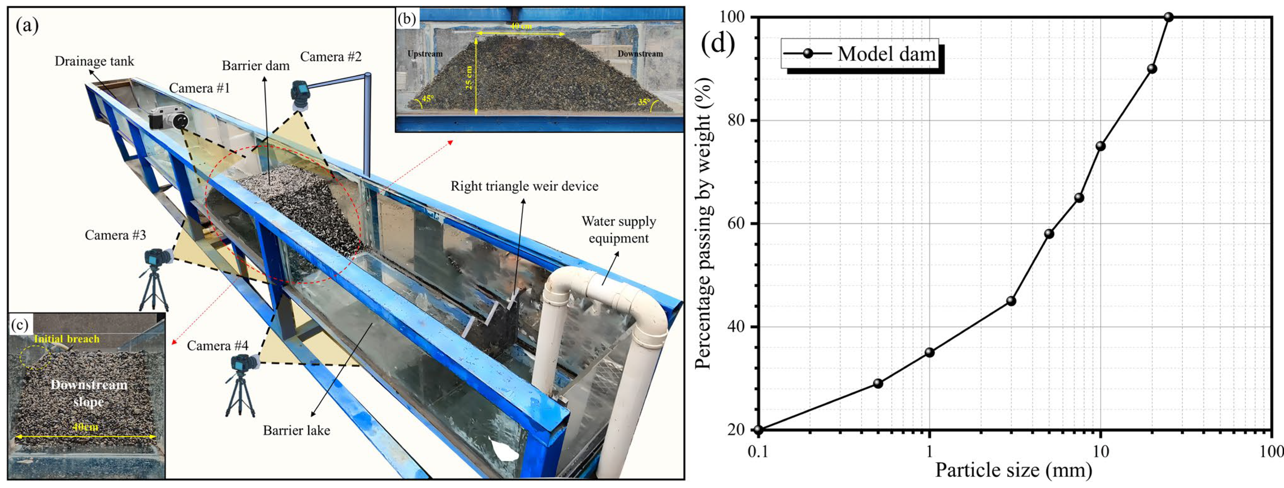
Figure 1. The setup of the model test: (a) panoramic view of the model test setup; (b) side view of the dam; (c) downstream view of the dam; (d) the model dam Grain size distribution curves.
Water 17 03310 g001
Figure 2. Schematic layout of internal grouting measures: (a) grouting depth; (b) Test B-3, D-3; (c) Test B-1, D-1; (d) Test A-3, C-3; (e) Test B-2, D-2; (f) Test A-1, C-1; (g) Test A-2, C-2; (h) Test A-4, C-4; (i) pre-experimental break stable side view; (j) pre-experimental break stable top view.
Water 17 03310 g002
Figure 3. (a1f1) The process of the landslide dam failure at Test A-1; (a2f2) The process of the landslide dam failure at the pre-experiment.
Water 17 03310 g003
Figure 4. Outflow discharge hydrograph: (a) the blank group; (b) blank group dam break process; (c) blank group final breach; (d) Group A; (e) Group B; (f) Group C; (g) Group D.
Water 17 03310 g004
Figure 5. Parameters of final breach size for all tests.
Water 17 03310 g005
Figure 6. (ad) Test A-1~4 final breach profile morphology; (e) Test A-1~4 the final shape of the breach.
Water 17 03310 g006
Figure 7. (ad) Test C-1~4 final breach profile morphology; (e) Test C-1~4 the final shape of the breach.
Water 17 03310 g007
Figure 8. (af) Tests B-1~3 and D-1~3 final breach profile morphology; (g) Tests B-1~3 and D-1~3 the final shape of the breach.
Water 17 03310 g008
Figure 9. (af) Evolution of dam longitudinal profiles.
Water 17 03310 g009
Figure 10. (a) Height of residual dam; (b) Quality of residual dam.
Water 17 03310 g010
Figure 11. (ap) Residual morphology of the dam.
Water 17 03310 g011
Figure 12. (ah) Influence of consolidation on the flow regime of routed streams (grouting depth: 0.5H).
Water 17 03310 g012
Table 1. Characteristic dimensions of model dam and natural landslide dams.
H/CSuSdH/B V d 1 / 3 /H V l 1 / 3 /H
Natural landslide dams0.2–3.011–45°11–45°0.02–10.5–50.2–10
Model dam0.62545°35°0.251.742.05
Notes: Where H is the height of the dam, B is the width of the dam base, Vd is the volume of the dam, and Vl is the volume of the barrier.
Table 2. Designed experimental groups.
GroupTestGrouting Point Distribution PositionGrouting DepthArrangementabQin/(L/s)
Blank\\0\001.35
Pre-experiment\Uniformly distributed in
the dam
0.5H1 × 210\1.35
A1Uniformly distributed in
the dam
0.5H1 × 210\1.35
20.5H2 × 1\201.35
30.5H2 × 210201.35
40.5H2 × 220101.35
B1Concentrated distribution in
the breach
0.5H2 × 110\1.35
20.5H1 × 2\51.35
30.5H3 × 15\1.35
C1Uniformly distributed in
the dam
0.75H1 × 210\1.35
20.75H2 × 1\201.35
30.75H2 × 210201.35
40.75H2 × 220101.35
D1Concentrated distribution in
the breach
0.75H2 × 110\1.35
20.75H1 × 2\51.35
30.75H3 × 15\1.35
Disclaimer/Publisher’s Note: The statements, opinions and data contained in all publications are solely those of the individual author(s) and contributor(s) and not of MDPI and/or the editor(s). MDPI and/or the editor(s) disclaim responsibility for any injury to people or property resulting from any ideas, methods, instructions or products referred to in the content.