Abstract
Stepped spillways, as highly effective energy dissipation facilities, have been widely applied in hydraulic engineering. By introducing an inclination angle to the horizontal step surface, either energy dissipation efficiency or sediment transport capacity can be enhanced. The manner and size of vortices within the steps vary with changes in the inclination angle and spillway slope, enhancing energy dissipation through momentum exchange between the main flow and these vortices. This study, drawing upon data in the literature and numerical simulations, investigates the influence of a spillway slope and step inclination angle on the energy dissipation characteristics of inclined stepped spillways. Results indicate that the energy dissipation rate decreases with an increasing spillway slope while increasing with a greater upward inclination of the step’s horizontal surface. However, changes in both parameters show a limiting effect on vortex development. As the spillway slope decreases and the step inclination angle increases, the rate of vortex size expansion diminishes. Finally, an inclination/slope ratio is proposed to characterize the energy dissipation effect of inclined steps, and an empirical formula relating the energy dissipation rate to the relative critical depth, relative spillway height, and inclination/slope ratio is established, with errors controlled within 10%.
1. Introduction
Spillways are among the most important hydraulic structures that control the flow of water from a dam reservoir into the downstream river. A spillway structure consists of several components: the approach channel, crest, chute, and energy dissipater at the downstream end [1]. The accurate design of the chute is essential for the efficiency of the spillway [2]. The flow over the crest contains high kinetic energy, which increases further down the chute and can cause cavitation due to reduced pressure. Additionally, this energy can pose a substantial risk of scouring downstream of the spillway chute [3]. The use of a stepped spillway as a hydraulic structure to reduce the energy of the flow dates back approximately 3500 years [4]. However, some relevant hydraulic aspects of these spillways remain un-known. In recent decades, new dam construction technologies such as the use of roller-compacted concrete (RCC) have increased the development and attention to this type of spillway [5,6]. The wide application of stepped spillways imposes specific requirements on their hydraulic performance, particularly regarding energy dissipation enhancement, unit discharge capacity increase, cavitation risk mitigation, and downstream scour reduction. Researchers have addressed these requirements by developing design modifications that incorporate specific features on the step surfaces. While some of this research is academically oriented, much of it aims to solve practical engineering problems.
Setting vertical or curved end sills at the end of the steps can enhance energy dissipation efficiency by approximately 5% to 10%, with curved end sills showing a more pronounced effect [7]. Modifying the step cross-sectional shape, such as adopting a V-shaped design (by carving a V-shaped groove with its vertex located at the center of the step width), can optimize hydrodynamic characteristics under skimming flow conditions. By increasing the angle of the V-shaped groove (i.e., the angle at the vertex of the V-shaped groove), the spreading of the flow is improved and energy dissipation is further enhanced [8]. The flow in stepped spillways can be divided into non-aerated and aerated zones. In the non-aerated zone, due to pressure along the vertical face and the increasing flow velocity [9,10], the step surface is prone to cavitation damage [11], with the risk increasing as the unit discharge becomes larger. The high air concentration in the aerated zone effectively mitigates or eliminates cavitation damage near the pseudo-bottom and sidewalls. Aerators can be added to shift the starting point of air entrainment upstream, enabling the spillway to function effectively under higher unit discharges [12,13,14,15]. For embankment dam stepped spillways, precast concrete step elements are placed as overtopping protections system, and they are often inclined downward (downward slope) to facilitate the drainage of the protective layer placed between the earthfill material and the elements [16]. Conversely, elevating the step surface (upward slope) can effectively increase flow resistance, thereby enhancing energy dissipation [17].
Regardless of the variation in step forms, the primary purpose is to reduce the energy at the spillway outlet, thereby minimizing the size of downstream energy dissipation structures. For different step structures, as the incoming flow rate increases, the flow regime transitions sequentially through the nappe, transitional, and skimming flow states (see Figure 1) [18]. In the nappe flow regime, energy dissipation is typically more effective [19,20,21]. However, on long stepped spillways, due to the larger flow rate, the total energy dissipation under the stable skimming flow is greater [22]. This is because, in the skimming flow regime, the areas around the step surface (or additional devices on the step) are entirely filled with water, creating strong internal vortices. Significant momentum exchange occurs between the main dissipation flow and the internal water, further enhancing energy dissipation. The characteristics of these vortices, including their scale and intensity distribution, are influenced by factors such as the slope of the spillway, the step layout, and the geometric dimensions of the steps [23]. Based on this understanding, Ikinciogullari’s research demonstrates that staggered step designs outperform inline step designs in terms of energy dissipation efficiency [24]. Furthermore, their subsequent study highlighted that two-cycle triangular labyrinth models are more effective at energy dissipation than single-cycle models [25]. Similarly, Morovati et al. [26] investigated end sill steps with openings and proposed four configurations: centered, offset, inline, and staggered. They found that staggered openings significantly reduced residual energy at the spillway outlet. Following this line of inquiry, Ma et al. [27] compared interval-pooled stepped spillways, pooled stepped spillways, and traditional flat-panel stepped spillways, concluding that the interval-pooled configuration exhibited superior energy dissipation performance.
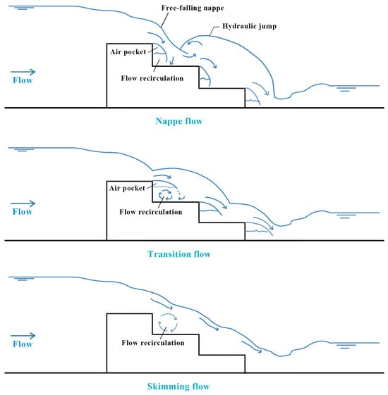
Figure 1.
Schematic diagram of nappe flow, transition flow, and skimming flow.
Although various designs that outperform traditional stepped spillways in energy dissipation have been developed, inclined steps with upstream or downstream slopes are more widely used in practice due to their construction simplicity. However, existing studies have primarily focused on the relationship between geometric parameters of inclined steps and energy dissipation, lacking a systematic exploration of the underlying mechanisms. To address this, this study investigates the independent effects of spillway slope and step inclination angle on energy dissipation under skimming flow conditions, as well as their combined influence. The research aims to reveal the mechanism by analyzing how the key vortex scales affecting energy dissipation change with variations in the structural parameters of inclined steps. Based on experimental data from previous studies, numerical simulations are employed to separately examine the individual and combined effects of inclination angle and spillway slope on energy dissipation performance. Finally, a new characteristic parameter is proposed to represent the geometric structure of inclined steps, providing deeper insights into their impact on energy dissipation efficiency.
2. Experimental Design
2.1. Data Selection
Inclined stepped spillways can be classified into positive-sloped and negative-sloped configurations based on the inclination degree of the traditional horizontal step surface [28]. Let θ denote the inclination angle between the step surface and the horizontal plane, where θ = 0 represents the traditional step structure and θ > 0 and θ < 0 indicate upward inclined step and downward inclined step, respectively (see Figure 2). The slope α for both traditional and inclined stepped spillways refers to the angle between the pseudo-bottom (i.e., the line connecting the step edges) and the horizontal direction.
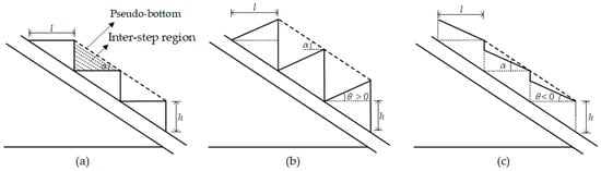
Figure 2.
Stepped spillway geometries: (a) horizontal steps; (b) upward inclined step; (c) downward inclined step.
This study utilizes energy dissipation data from four sources in the literature on inclined stepped spillways under skimming flow conditions, where stable vortex regions form between the step surfaces and the main flow. Table 1 lists the geometric parameters and inflow conditions of the inclined stepped spillways from each source. Additionally, physical model tests were conducted to capture detailed flow characteristics and provide a foundation for validating numerical simulations. Numerical simulations, validated against corresponding physical model tests, were employed to generate the vortex flow fields presented in this study, thereby ensuring the fidelity and reliability of the results.

Table 1.
Data of hydraulic model test and numerical simulation.
2.2. Grid Convergence Analysis
This study further employs FLOW-3D v11.2 software to simulate vortex flow fields in traditional and inclined stepped spillways. Under the premise of neglecting air entrainment, we systematically analyzed the influence of different step structures on vortex flow fields and energy dissipation effects. To validate the accuracy of the numerical simulation and grid independence, a typical skimming flow stepped spillway model was constructed. The model parameters were set as follows: total height of 1.674 m, total width of 0.425 m, a chute with a slope of 1:0.75 following the overflow weir, inclination angle θ = 0, and a total of forty-six steps. The computational domain for the numerical simulation extends from 0.635 m upstream of the stepped spillway entrance to 2.665 m downstream at the river channel outlet. The upstream boundary is set as a volume flow rate inlet boundary, the downstream boundary as an outflow boundary, the left and right banks and bottom as wall boundaries, and the top as a symmetry boundary, as shown in Figure 3.
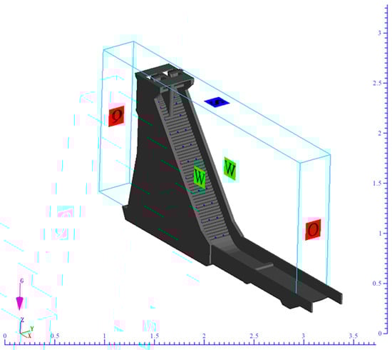
Figure 3.
Schematic diagram of boundary conditions.
To select an appropriate mesh, we conducted a grid convergence index (GCI) test on multiple computational grids. The GCI is a widely recognized method for evaluating discretization error, with larger values indicating greater error. Generally, a GCI below 5% is considered acceptable to ensure computational accuracy. In similar research, Soydan Oksal et al. [32,33] employed the GCI method to validate computational grids while analyzing trapezoidal weir flows, emphasizing the importance of mesh refinement in accurately predicting flow characteristics and energy dissipation rates. The analysis followed the Richardson extrapolation method as described by Celik et al. [34]. Three different meshes—fine, medium (see Figure 4), and coarse—were used to examine the influence of grid size on the accuracy of numerical results. Table 2 summarizes the characteristics of the three computational grids, with a grid refinement factor of 1.3 as recommended by Celik et al. [34].
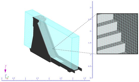
Figure 4.
G2 3D grid example.
Table 2.
Characteristics of the meshes tested in the convergence analysis.
A representative cell size (S) is defined as
where Vi is the volume and N is the total number of cells used for the computation.
Let S1, S2, and S3 be the representative cell sizes for different refinement levels, where S1 < S2 < S3 and r21 = S2/S1, r32 = S3/S2. The apparent order (p) is calculated as
where ε21 = ϕ2 − ϕ1 and ε32 = ϕ3 − ϕ2, with φ representing the solution obtained on different refined grids.
The grid convergence index (GCI) is calculated as
Grid convergence analysis was conducted by selecting flow depth (fd) and free surface elevation (el) at various points along the chute section of the stepped spillway (from the first step to the forty-sixth step) as discrete characteristic quantities. In the visualization, the X-axis represents data at intervals of 0.05 m along the chute section; the Y-axis indicates the GCI categories for flow depth (fd) and free surface elevation (el), specifically el21, el32, fd21, and fd32; while the Z-axis displays the corresponding GCI values. Here, fd32 and fd21 represent the grid convergence index (GCI) for flow depth of GCI32 (the grid convergence index of computational grid G3 relative to medium grid G2) and GCI21 (the grid convergence index of computational grid G2 relative to fine grid G1), respectively. Similarly, el32 and el21 represent the GCI32 and GCI21 for free surface elevation. Calculation results show that the maximum values of GCI21 for free surface elevation and flow depth are 1.48% and 1.48% (see Figure 5), respectively, both occurring at the bottom of the stepped spillway. By comparing the results of G2 and G1, it is evident that the error in G2 has significantly decreased. Therefore, to balance computational accuracy and efficiency, this study adopts the grid size of G2 for subsequent simulations.
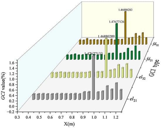
Figure 5.
Grid convergence index for flow depth and free surface elevation.
2.3. Validation of Numerical Simulation Accuracy
To validate the numerical model, a physical model of the Fengxi Reservoir was constructed with a scale ratio of 1:40. The model, encompassing a water supply system, reservoir, dam, discharge structures, and a simplified upstream and downstream river channel (240 m and 400 m prototype length, respectively), measures 16 m × 6.0 m × 1.2 m (length × width × height). Specifically focusing on the hydraulic performance of horizontal stepped spillways, water surface profiles, measured multiple times using rulers and then time-averaged, served as the primary validation parameter. Figure 6a–c illustrate the flow conditions in the chute section of the physical model test, while Figure 6d compares the numerically simulated water surface profile with measured water depths at specific steps. Results indicate that discrepancies between the calculated water surface profile and measured data are primarily concentrated at the step ends, with overall errors controlled within 2%. The maximum error of 1.09% occurs at X = 0.799 m, corresponding to a measured water depth of 0.032 m.
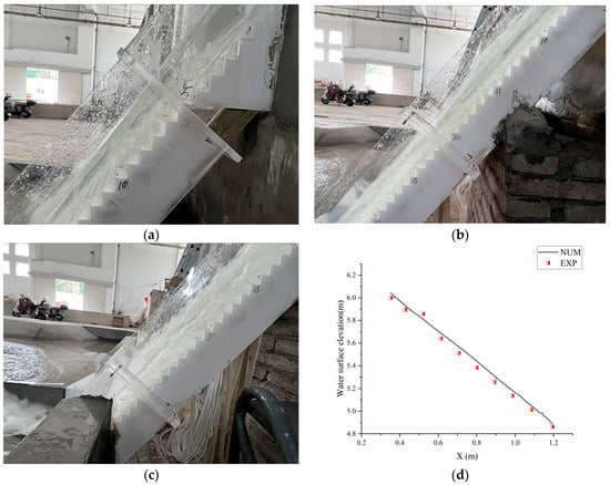
Figure 6.
Comparison of water surface profiles between numerical simulation and physical model test; flow regime at steps 1#–10# (a); flow regime at steps 10#–30# (b); flow regime at steps 30#–46# (c); water surface profile (d).
3. Results
3.1. Energy Dissipation Rate
The energy dissipation rate is a crucial indicator for evaluating the energy dissipation performance of stepped spillways. It represents the ratio of the cumulative energy consumed at the flow cross-section to the total incoming energy, which can be expressed as
where E0 is the total incoming energy of the spillway (m), Er is the residual energy at the flow cross-section of the spillway (m), and EL is the cumulative energy dissipated at the flow cross-section of the spillway (m). Figure 7, based on data from Chinnarasri et al. [29,30], illustrates the variation trend of the energy dissipation rate with relative critical water depth dc/h under different inclination angles θ and spillway slopes α. The results indicate that under skimming flow conditions, regardless of the type of inclined steps, the energy dissipation rate decreases as the relative critical water depth increases. Furthermore, under the same inflow conditions, the energy dissipation rate exhibits opposite trends with changes in inclination angle and spillway slope: at the same inclination angle, the energy dissipation rate decreases as the spillway slope increases, while at the same spillway slope, the energy dissipation rate increases as the inclination angle increases. In stepped spillways, energy dissipation is primarily achieved through momentum exchange between the vortex region and the main flow. Changes in the geometric structure, such as spillway slope and inclination angle, effectively influence the extent of the vortex region. Further analysis of the vortex flow field was conducted to explore the effects of spillway slope and inclination angle on energy dissipation.
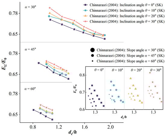
Figure 7.
Comparative analysis chart of energy dissipation rates (EL/E0) for different step configurations [30].
3.2. Vortex Flow Field Characteristics
The internal vortex structures formed on the surface of stepped spillways require high energy from the main flow to maintain their motion. Additionally, the virtual bottom formed by the vortices further dissipates the kinetic energy of the main flow compared to traditional smooth spillways. Therefore, the characteristics of the vortex flow field significantly influence the energy dissipation effect of the spillway. Figure 8 shows the vortex flow fields of traditional stepped spillways under different slopes, with a relative critical water depth dc/h of 1.08. While maintaining a constant step height, the spillway slope increases as the step length decreases.
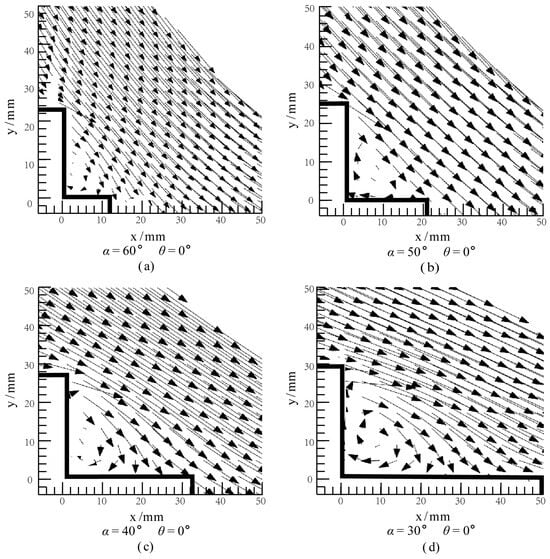
Figure 8.
Velocity vector diagram of a single-step stair under different slope ratios. (a) α = 60°, θ = 0°; (b) α = 50°, θ = 0°; (c) α = 40°, θ = 0°; (d) α = 30°, θ = 0°.
It can be observed that the vortex size is constrained by the internal space surrounded by the step surface. As the slope increases, the vortex size significantly decreases. When combined with the results of energy dissipation rate variation with chute slope (α) in Figure 8, it can be concluded that the increase in slope leads to a reduction in vortex size, resulting in decreased kinetic energy consumption to maintain vortex motion, and consequently lower energy dissipation rates. However, from Figure 8c,d, it can be observed that although the vortex size at α = 30° is slightly larger than at α = 40°, the growth of the vortex size in the transverse direction significantly slows down, especially at α = 30°, where the vortex size no longer changes significantly with increasing step length, exhibiting a clear limitation of the trend. For this flow state (dc/h = 1.08), α = 40° is approaching a critical state. Moreover, for both the α = 30° and α = 40° cases, in addition to the main flow maintaining the vortex size, it is evident that part of the water flow directly impacts the step surface, also producing some energy dissipation, and this portion may have an even greater energy dissipation effect. The change in the energy dissipation rate under varying slopes in Figure 7 also verifies this point: under the same inflow conditions, the change in energy dissipation rate when α increases from 30° to 45° is significantly greater than when it increases from 45° to 60°. Therefore, the energy dissipation rate cannot be summarized solely from the perspective of vortex size and geometry.
Further analysis of the vortex flow field characteristics under inclined steps was conducted. Figure 9 shows the changes in the vortex flow field under skimming flow conditions with a relative critical water depth dc/h of 4.8 and a spillway slope α of 26.6° as the inclination angle gradually increases from −20° to 20° (θ = −20°, −10°, 0°, 10°, 20°). For cases where the inclination angle θ < 0 (Figure 8a,b), when θ is −10° and −20°, due to the downward layout, the vortices expand more quickly to the lower surface of the step, resulting in further reduction of vortex size compared to traditional steps, especially evident when θ is −20°. When the inclination angle θ > 0, compared to the limited transverse expansion of vortices in traditional steps (θ = 0, see Figure 8c), the vortex size can still further in-crease when θ is 10° and 20°, and the vortex size increases correspondingly with the increase of the inclination angle. However, compared to the case of θ < 0, the growth rate of the vortex size slows down significantly, exhibiting a limit. Wu et al. [35] demonstrated that under skimming flow conditions, there is a positive correlation between the residual energy of outflow and the area of internal structures formed by the step surface. According to the changes in internal structure area shown in Figure 9, when θ decreases from 0° to −20°, the area decreases sharply by 78%, and the energy dissipation rate drops from 0.51 to 0.29, while when θ increases from 0° to 20°, the area increases by 59%, and the energy dissipation rate rises from 0.51 to 0.56. On one hand, the area reduction effect caused by the downward inclination is greater than the area increase effect caused by the upward inclination. On the other hand, for traditional steps, under the same unit area increase or decrease, the impact of upward inclination on energy dissipation is more significant. In summary, whether for traditional steps or inclined steps, when considering vortex development, it is essential to fully consider the internal region parameters of the steps, especially the combined effect of spillway slope and inclination angle.
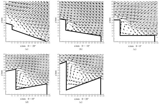
Figure 9.
Flow field under different stair inclination angles. (a) θ = −20°; (b) θ = −10°; (c) θ = 0°; (d) θ = 10°; (e) θ = 20°.
3.3. Energy Dissipation Assessment Under the Combined Influence of α and θ
Considering the combined effect of the spillway slope and inclination angle on energy dissipation, this paper proposes the use of a dimensionless parameter, the slope/inclination ratio θ/α, to characterize the joint effect of the inclination angle and spillway slope on the energy dissipation of inclined steps. Figure 10 shows the variation trend of energy dissipation rate EL/E0 with the slope/inclination ratio θ/α under different relative critical water depths dc/h.
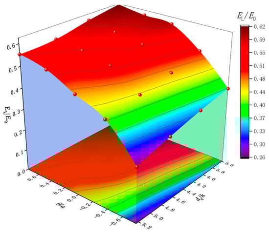
Figure 10.
Energy dissipation rate under different slope ratios.
The results indicate that under different inflow conditions, as the slope/inclination ratio θ/α increases, the energy dissipation rate EL/E0 shows a trend of rapid increase initially, followed by a gradual leveling off. Taking dc/h = 4.8328 as an example, although the slope/inclination ratio increased by 0.769 for both downward and upward inclined steps, in terms of energy dissipation rate, the downward inclined steps increased from 0.292 to 0.555, an increase of 91%, while the upward inclined steps increased from 0.510 to 0.555, an increase of only 9%. As the θ/α value increases, either a larger θ value or a smaller α value will expand the vortex development space enclosed by the virtual bottom and step surface. However, for both traditional and inclined steps, the development of vortices does not completely correspond to the area change. Overall, the influence of the slope/inclination ratio on inclined steps also exhibits a limiting effect, where the improvement in the energy dissipation effect will tend to level off after the θ/α value exceeds a certain critical value.
To quantitatively assess the impact of inclined step geometric parameters on the energy dissipation effect of spillways, this paper proposes an empirical formula for estimating the energy dissipation rate:
where EL/E0 is the energy dissipation rate; dc/h is the relative critical water depth; θ/α is the slope/inclination ratio; Δz0/l is the ratio of spillway weir height Δz0 to step length l; and a, b, c, d, and g are coefficients to be determined.
Moreover, the inlet conditions of stepped spillways significantly affect the energy dissipation rate, such as the curved weir free-surface inlet, broad-crested weir free-surface inlet, and pressurized gate inlet. To determine the coefficients in Equation (5), this paper used 91 sets of data from Chinnarasri et al. [29,30], Li et al. [31], and Arosquipa Nina et al. [14], covering different spillway slopes (26.6°, 30°, 45°, and 60°) and inclination angles (−22.3° to 30°). Using regression analysis, the development of vortices using formulas for calculating the energy dissipation rate of inclined steps under different inlet conditions were obtained (Equations (6)–(8)):
For free-surface inlet conditions, with α = 30° (θ = 0°, 10°, 20°, and 30°), α = 45° (θ = 0°, 10°, 20°, and 30°), α = 60° (θ = 0°, 10°, 20°, and 30°) [29,30]:
For free-surface inlet conditions, with α = 26.6° (θ = −20°, −10°, 0°, 10°, and 20°) [31]:
For pressurized aerated flow conditions, with α = 45° (θ = 0°, −11.3°, and −23.3°) [14]:
As presented in Table 3, Equations (6) and (7) exhibit relatively high fitting accuracy with R2 values of 0.882 and 0.996, respectively. Equation (7) shows slightly better performance with lower RMSE, RSE, and MAE values compared to Equation (6). However, Equation (8) demonstrates a lower R2 value of 0.704 and higher error metrics (RSE = 0.321), indicating a poorer fit to the data. This may be attributed to the more comprehensive consideration of aeration effects in the flow in Arosquipa Nina’s study. This effect, due to the significant fluctuations caused by water–air interactions at the end of the spillway, has a certain impact on the measurement results of the energy dissipation rate. Figure 11 compares the predicted values of energy dissipation rate for different inclined steps using Equations (6)–(8) with the actual values. The results show that Equation (5) can predict the energy dissipation rate relatively accurately, with all data errors within ±10%, the minimum error being 0.11% and the maximum error being 9.36%. Additionally, for broad-crested weir inlet conditions, the ratio of spillway weir height to step length (Δz0/l = Δz0/h × h/l = N × tanα) reflects the overall height (number of steps) and slope of the spillway. When the spillway is sufficiently long, the skimming flow tends to form a uniform flow with almost unchanged cross-sectional hydraulic characteristics along the length [36], at which point the residual energy Er will remain constant. The energy dissipation rate calculated in this case differs from that under conditions where uniform flow has not been achieved.
Table 3.
Comparison of error metrics for different equations.
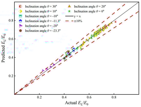
Figure 11.
Predicted vs. actual energy dissipation rate.
4. Conclusions
This paper analyzed 91 sets of original data and conducted numerical simulations to study the influence of inclined step geometric parameters on energy dissipation characteristics. The following conclusions were drawn:
- (1)
- In inclined stepped spillways, the energy dissipation rate decreases with increasing spillway slope but increases with increasing inclination angle.
- (2)
- Changes in both the spillway slope α and inclination angle θ lead to changes in the size of internal vortices in the steps. When the slope decreases or the inclination angle increases to a certain critical value, a marginal effect is observed, i.e., the growth rate of the vortex size decreases.
- (3)
- The slope/inclination ratio θ/α is proposed to characterize inclined steps, and it is found that its relationship with the energy dissipation rate also follows the law of diminishing marginal effects. Based on the original data, a relationship between the energy dissipation rate, relative critical water depth, relative spillway height, and slope/inclination ratio was established, with errors controlled within 10%.
In practical engineering design, it is necessary to comprehensively consider site conditions and economic factors to reasonably select the combination of inclined step θ and α to achieve the optimal value of θ/α, thereby optimizing energy dissipation while maintaining the total height of the spillway.
Author Contributions
Conceptualization, J.M.; data curation, Z.S. and Q.G.; formal analysis: J.M. and Y.Z.; investigation, J.M. and K.X.; methodology, Q.Y. and G.X.; writing—original draft, J.M.; writing—review and editing, Y.Z., Q.Y. and J.Q. All authors have read and agreed to the published version of the manuscript.
Funding
This study was supported by the Zhejiang Provincial Natural Science Foundation Joint Fund Project [Grant No. LZJWY23E090002], the Zhejiang Provincial Joint Fund Key Project [Grant No. LZJWZ24E090003], and the National College Student Innovation Training Program Fund Project [Grant No. 202411481005].
Data Availability Statement
All relevant data are contained within the manuscript.
Conflicts of Interest
This original, unpublished version is not currently considered for publication in other journals. The authors declare no conflict of interest.
Abbreviations
| θ | Inclination angle of steps, ° |
| α | Spillway slope, ° |
| h | Step height, m |
| l | Step length, m |
| dc | Spillway weir height, m |
| r | Grid refinement factor |
| S | Cell size |
| Vi | Volume of cells |
| N | Total number of cells used for the computation |
| p | Apparent order |
| ϕ | Representing the solution obtained on grids |
| GCI | Grid convergence index |
| fd | Flow depth, m |
| el | Free surface elevation, m |
| η | Energy dissipation rate |
| E0 | Total incoming energy of the spillway, m |
| Er | Residual energy at the flow cross-section of the spillway, m |
| EL | Cumulative energy dissipated at the flow cross-section of the spillway, m |
| Δz0 | Spillway weir height, m |
| a | Correction coefficients |
| b | Correction coefficients |
| c | Correction coefficients |
| d | Correction coefficients |
| g | Correction coefficients |
| R2 | Coefficient of determination |
References
- Afaridegan, E.; Amanian, N.; Shanehsazzadeh, A.; Parsaie, A. Characteristics of Flow Passing over Hydrofoil Crested Stepped Spillway. Alex. Eng. J. 2024, 108, 897–910. [Google Scholar] [CrossRef]
- U.S. Department of the Interior, Bureau of Reclamation. Design of Small Dams; US Department of the Interior, Bureau of Reclamation: Washington, DC, USA, 1987.
- Khatsuria, R.M. Hydraulics of Spillways and Energy Dissipators; CRC Press: Boca Raton, FL, USA, 2004. [Google Scholar]
- Chanson, H. Energy Dissipation on Stepped Spillways and Hydraulic Challenges—Prototype and Laboratory Experiences. J. Hydrodyn. 2022, 34, 52–62. [Google Scholar] [CrossRef]
- Felder, S.; Chanson, H. Energy Dissipation down a Stepped Spillway with Nonuniform Step Heights. J. Hydraul. Eng. 2011, 137, 1543–1548. [Google Scholar] [CrossRef]
- Chanson, H. Historical Development of Stepped Cascades for the Dissipation of Hydraulic Energy. Trans. Newcom. Soc. 2000, 72, 295–318. [Google Scholar] [CrossRef]
- Jahad, U.A.; Chabuk, A.; Al-Ameri, R.; Majdi, H.S.; Majdi, A.; Al-Ansari, N.; Abed, S.A. Flow Characteristics and Energy Dissipation over Stepped Spillway with Various Step Geometries: Case Study (Steps with Curve End Sill). Appl. Water Sci. 2024, 14, 60. [Google Scholar] [CrossRef]
- Bai, Z.; Wang, Y.; Zhang, J. Pressure Distributions of Stepped Spillways with Different Horizontal Face Angles. Proc. Inst. Civ. Eng.—Water Manag. 2018, 171, 299–310. [Google Scholar] [CrossRef]
- Sanchez Juny, M.; Bladé, E.; Dolz, J. Pressures on a Stepped Spillway. J. Hydraul. Res. 2007, 45, 505–511. [Google Scholar] [CrossRef]
- Amador, A.; Sánchez-Juny, M.; Dolz, J. Characterization of the Nonaerated Flow Region in a Stepped Spillway by PIV. J. Fluids Eng. 2006, 128, 1266–1273. [Google Scholar] [CrossRef]
- Matos, J.; Novakoski, C.K.; Ferla, R.; Marques, M.G.; Dai Prá, M.; Canellas, A.V.B.; Teixeira, E.D. Extreme Pressures and Risk of Cavitation in Steeply Sloping Stepped Spillways of Large Dams. Water 2022, 14, 306. [Google Scholar] [CrossRef]
- Li, S.; Zhang, J.; Xu, W. Numerical Investigation of Air–Water Flow Properties over Steep Flat and Pooled Stepped Spillways. J. Hydraul. Res. 2018, 56, 1–14. [Google Scholar] [CrossRef]
- Hunt, S.L.; Kadavy, K.C. Inception Point for Stepped Chute Designs with Multiple Sections of Different Step Heights. J. Hydraul. Eng. 2021, 147, 06021001. [Google Scholar] [CrossRef]
- Arosquipa Nina, Y.; Shi, R.; Wüthrich, D.; Chanson, H. Air–Water Flows and Head Losses on Stepped Spillways with Inclined Steps. J. Irrig. Drain. Eng. 2022, 148, 04022037. [Google Scholar] [CrossRef]
- Li, S.; Yang, J.; Li, Q. Numerical Modelling of Air-Water Flows over a Stepped Spillway with Chamfers and Cavity Blockages. KSCE J. Civ. Eng. 2020, 24, 99–109. [Google Scholar] [CrossRef]
- Zhou, Y.; Wu, J.; Zhao, H.; Hu, J.; Zhou, J.; Bai, F. Discussion of “Air–Water Flows and Head Losses on Stepped Spillways with Inclined Steps”. J. Irrig. Drain Eng. 2023, 149, 07023010. [Google Scholar] [CrossRef]
- Pandey, B.R.; K C, M.R.; Crookston, B.; Zenz, G. Numerical Investigation of Different Stepped Spillway Geometries over a Mild Slope for Safe Operation Using Multi-Phase Model. Water 2024, 16, 1635. [Google Scholar] [CrossRef]
- Zare, H.K.; Doering, J.C. Energy Dissipation and Flow Characteristics of Baffles and Sills on Stepped Spillways. J. Hydraul. Res. 2012, 50, 192–199. [Google Scholar] [CrossRef]
- Peyras, L.; Royet, P.; Degoutte, G. Flow and Energy Dissipation over Stepped Gabion Weirs. J. Hydraul. Eng. 1992, 118, 707–717. [Google Scholar] [CrossRef]
- Chamani, M.R.; Rajaratnam, N. Characteristics of Skimming Flow over Stepped Spillways. J. Hydraul. Eng. 1999, 125, 361–368. [Google Scholar] [CrossRef]
- Chamani, M.R.; Rajaratnam, N. Jet Flow on Stepped Spillways. J. Hydraul. Eng. 1994, 120, 254–259. [Google Scholar] [CrossRef]
- Chanson, H. Comparison of Energy Dissipation between Nappe and Skimming Flow Regimes on Stepped Chutes. J. Hydraul. Res. 1994, 32, 213–218. [Google Scholar] [CrossRef]
- Zhou, Y.; Wu, J.; Ma, F.; Qian, S. Experimental Investigation of the Hydraulic Performance of a Hydraulic-Jump-Stepped Spillway. KSCE J. Civ. Eng. 2021, 25, 3758–3765. [Google Scholar] [CrossRef]
- Ikinciogullari, E. A Novel Design for Stepped Spillway Using Staggered Labyrinth Trapezoidal Steps. Flow Meas. Instrum. 2023, 93, 102439. [Google Scholar] [CrossRef]
- Ikinciogullari, E. Energy Dissipation Performance of Labyrinth and Harmonic Stepped Spillways. J. Hydroinform. 2024, 26, 2668–2682. [Google Scholar] [CrossRef]
- Morovati, K.; Homer, C.; Tian, F.; Hu, H. Opening Configuration Design Effects on Pooled Stepped Chutes. J. Hydraul. Eng. 2021, 147, 06021011. [Google Scholar] [CrossRef]
- Ma, X.; Zhang, J.; Hu, Y. Analysis of Energy Dissipation of Interval-Pooled Stepped Spillways. Entropy 2022, 24, 85. [Google Scholar] [CrossRef] [PubMed]
- Kherbache, K.; Chesneau, X.; Zeghmati, B.; Abide, S.; Benmamar, S. The Effects of Step Inclination and Air Injection on the Water Flow in a Stepped Spillway: A Numerical Study. J. Hydrodyn. 2017, 29, 322–331. [Google Scholar] [CrossRef]
- Chinnarasri, C.; Wongwises, S. Flow Patterns and Energy Dissipation over Various Stepped Chutes. J. Irrig. Drain. Eng. 2006, 132, 70–76. [Google Scholar] [CrossRef]
- Chinnarasri, C.; Wongwises, S. Flow Regimes and Energy Loss on Chutes with Upward Inclined Steps. Can. J. Civ. Eng. 2004, 31, 870–879. [Google Scholar] [CrossRef]
- Li, S.; Yang, J. Effects of Inclination Angles on Stepped Chute Flows. Appl. Sci. 2020, 10, 6202. [Google Scholar] [CrossRef]
- Soydan Oksal, N.G.; Akoz, M.S.; Simsek, O. Numerical Modelling of Trapezoidal Weir Flow with RANS, LES and DES Models. Sādhanā 2020, 45, 91. [Google Scholar] [CrossRef]
- Soydan Oksal, N.G.; Akoz, M.S.; Simsek, O. Experimental Analysis of Flow Characteristics over Hydrofoil Weirs. Flow Meas. Instrum. 2021, 79, 101867. [Google Scholar] [CrossRef]
- Celik, I.B.; Ghia, U.; Roache, P.J.; Freitas, C.J.; Coleman, H.; Raad, P.E. Procedure for Estimation and Reporting of Uncertainty Due to Discretization in CFD Applications. J. Fluids Eng. 2008, 130, 078001. [Google Scholar] [CrossRef]
- Wu, J.; Qian, S.; Wang, Y.; Zhou, Y. Residual Energy on Ski-Jump-Step and Stepped Spillways with Various Step Configurations. J. Hydraul. Eng. 2020, 146, 06020002. [Google Scholar] [CrossRef]
- Zhou, Y.; Wu, J.; Ma, F.; Hu, J. Uniform Flow and Energy Dissipation of Hydraulic-Jump-Stepped Spillways. Water Supply 2020, 20, 1546–1553. [Google Scholar] [CrossRef]
Disclaimer/Publisher’s Note: The statements, opinions and data contained in all publications are solely those of the individual author(s) and contributor(s) and not of MDPI and/or the editor(s). MDPI and/or the editor(s) disclaim responsibility for any injury to people or property resulting from any ideas, methods, instructions or products referred to in the content. |
© 2025 by the authors. Licensee MDPI, Basel, Switzerland. This article is an open access article distributed under the terms and conditions of the Creative Commons Attribution (CC BY) license (https://creativecommons.org/licenses/by/4.0/).