Article

Investigating the Frost Cracking Mechanisms of Water-Saturated Fissured Rock Slopes Based on a Meshless Model

1
School of Hydraulic Engineering, Zhejiang University of Water Resources and Electric Power, Hangzhou 310018, China
2
PowerChina Guiyang Engineering Corporation Limited, Guiyang 550081, China
3
College of Ocean Science and Engineering, Shanghai Maritime University, Shanghai 201306, China
4
School of Transportation and Civil Engineering, Nantong University, Nantong 226019, China
*
Authors to whom correspondence should be addressed.
Water 2025, 17(19), 2858; https://doi.org/10.3390/w17192858
Submission received: 18 August 2025 / Revised: 28 September 2025 / Accepted: 29 September 2025 / Published: 30 September 2025

Abstract

In global cold regions and seasonal frozen soil areas, frost heave failure of rock slopes severely endangers infrastructure safety, particularly along China’s Sichuan–Tibet and Qinghai–Tibet Railways. To address this, a meshless numerical model based on the smoothed particle hydrodynamics (SPH) method was developed to simulate progressive frost heave and fracture of water-saturated fissured rock masses—its novelty lies in avoiding grid distortion and artificial crack path assumptions of FEM as well as complex parameter calibration of DEM by integrating the maximum tensile stress criterion (with a binary fracture marker for particle failure), thermodynamic phase change theory (classifying fissure water into water, ice-water mixed, and ice particles), and the equivalent thermal expansion coefficient method to quantify frost heave force. Systematic simulations of fissure parameters (inclination angle, length, number, and row number) revealed that these factors significantly shape failure modes: longer fissures and more rows shift failure from strip-like to tree-like/network-like, more fissures accelerate crack coalescence, and larger inclination angles converge stress to fissure tips. This study clarifies key mechanisms and provides a theoretical/numerical reference for cold region rock slope stability control.

1. Introduction

In global cold regions and seasonal frozen soil areas, frost heave failure of rock slopes has become a critical factor restricting the construction and operational safety of infrastructure [1,2]. China’s cold regions, covering Northeast China, Northwest China, and the Qinghai–Tibet Plateau, host numerous major projects such as the Sichuan–Tibet Railway and Qinghai–Tibet Railway. Along these projects, a large number of rock slopes have long been exposed to freeze–thaw cycles, and their stability is significantly affected by frost heave [3]. When ambient temperatures drop below the freezing point, pore water in rock slope fissures undergoes phase transition and freezes. The volume expansion from water to ice generates frost heave forces reaching tens of megapascals. Meanwhile, temperature gradients formed based on heat conduction principles drive deep moisture migration and accumulation in fissures, causing frost heave forces to accumulate continuously and act periodically on fissure walls. This interaction between frost heave forces and rock mechanical properties promotes the initiation, propagation, and coalescence of fissures, significantly reducing rock strength and slope stability [4]. Engineering monitoring data indicate that structural diseases induced by frost heave account for 30–40% of existing rock slope projects in cold regions. Such issues not only increase engineering maintenance costs substantially but also pose potential threats to the safe operation of lifeline projects in the transportation and energy sectors, severely hindering regional economic sustainable development and social stability [5]. Therefore, research on the mechanism of frost heave failure in rock slopes is an urgent need for safety assurance in cold region engineering and an important direction in geotechnical engineering [6,7,8,9].
Research on frost heave failure of rock fissures at home and abroad mainly focuses on experimental studies, theoretical studies, and numerical simulations. Experimental studies can directly quantify the relationship between frost heave forces and rock failure, clarifying the mechanisms of factors such as temperature, moisture, and rock structure. For example, Tang et al. [10] explored the shear creep characteristics of soil–rock mixture (SRM)–concrete interfaces under freeze–thaw cycles and varying rock contents through shear creep tests. Liang et al. [11] investigated the effects of freeze–thaw cycles (FT) and fissure angles on the failure characteristics of fissured sandstone using quasi-static compression tests combined with acoustic emission (AE) multi-parameter monitoring and digital image correlation (DIC) technology. Chen et al. [12] discussed strength loss and failure characteristics of non-penetrating fissured rock masses with different fissure densities under freeze–thaw cycles via uniaxial compression tests. Zhou et al. [13] examined the influences of freeze–thaw cycles on mechanical properties and failure precursor characteristics of different rocks (sandstone, marble, and granite) through quasi-static compression tests. Yu et al. [14] studied the mechanical properties and energy evolution characteristics of excavation-unloaded rocks within freeze–thaw temperature ranges using freeze–thaw cycle tests with varying temperature ranges and triaxial unloading tests. Zhang et al. [15] analyzed the mechanical responses of tunnel lining structures and the progressive failure process of surrounding rock in gently inclined layered rock tunnels under freeze–thaw cycles through physical model tests. However, indoor tests cannot fully replicate complex geological environments in engineering, leading to deviations between results and practical scenarios. Additionally, specimen sizes are much smaller than actual rock masses, failing to reflect the heterogeneity of natural rocks (e.g., random fissure distribution and structural planes). Theoretical studies on frost heave failure of rock fissures are based on thermodynamics, solid mechanics, and porous media theory, establishing mathematical models to quantify the relationship between frost heave forces and rock failure. For instance, Zhang et al. [16] constructed a fully coupled thermo-mechanical model considering frost heave effects based on ordinary state-based peridynamics (OSBPD) to analyze the cracking characteristics of frozen rocks. Guo et al. [17] developed a new micro-frost heave model using discontinuous deformation analysis (DDA) to explore frost heave damage mechanisms in porous rocks, focusing on the coupling effect of pore characteristics and water saturation. Deng et al. [18] integrated fracture mechanics and circular hole expansion theory to establish a stability evaluation model for dangerous rock masses under freeze–thaw cycles, considering frost heave forces between structural planes and fracture toughness degradation of rock bridges. However, most theories assume rocks to be homogeneous and isotropic media, ignoring the heterogeneity of natural rocks (e.g., mineral distribution and random fissures), which is inconsistent with reality.
Numerical simulations of frost heave failure in rock fissures are based on theoretical models and calculation methods. By discretizing rock media and solving multi-physics coupling equations, they can simulate dynamic interactions between temperature, seepage, and stress fields, revealing the multi-factor mechanisms of frost heave failure. The finite element method was the first to be used for simulating freeze–thaw multi-field coupling in fissured rocks. For example, Sun et al. [19] developed a numerical simulation method for frost heave failure in fissured rocks based on the finite element method. Zhou et al. [20] proposed an improved extended finite element method to simulate interactions between multiple fissures. However, due to its grid-based discretization, the finite element method often requires predefining crack propagation paths or frequent grid reconstruction when handling dynamic crack propagation, which increases computational complexity and may introduce errors due to artificial assumptions, making it difficult to truly reflect the random and sudden crack propagation in rocks under complex stress conditions. The discrete element method, a meshless method different from the finite element method, treats rock masses as aggregates of independent units connected by contact relationships. It does not require predefined crack paths and can naturally simulate dynamic processes such as crack initiation, propagation, and branching, truly reflecting the randomness and suddenness of rock crack propagation. For instance, Zhao et al. [21] constructed a freeze–thaw damage model using the discrete element method (DEM) combined with AE monitoring technology, revealing the transition law of rock failure modes from brittle to plastic under different joint angles. Qiu et al. [22] established a microscale model of sandstone freeze–thaw cycles using particle flow code (PFC2D), systematically studying changes in mechanical properties of micro-fissured rock masses in terms of displacement, crack development, strain, and strength through numerical simulations. Shen et al. [23] proposed a DEM-based simulation method for freeze–thaw damage in water-filled fissured rocks, considering volume expansion of pore water and phase transition expansion of fissure water and solving the problem of water content changes after freeze–thaw cycles. Li et al. [24] numerically simulated the frost heave failure mechanism of cold-region earth-rock dam slope protection under the combined effects of moisture migration and ice loads by establishing a thermo-hydro-mechanical coupling model. Li et al. [25] used PFC2D to simulate freeze–thaw cycles and failure mechanisms under uniaxial compression, revealing the mechanical properties and failure mechanisms of rock-like specimens with arc-shaped fissures under freeze–thaw cycles. However, the discrete element method involves numerous mesoscale parameters, requiring complex parameter calibration before simulations, which limits its application in engineering practice. The smoothed particle hydrodynamics (SPH) method is a meshless particle method based on the Lagrangian framework. It discretizes continuous media into a series of particles carrying physical quantities such as mass, momentum, and energy and approximates the mechanical behavior of media through particle interactions. It does not rely on grid division and can naturally handle complex problems such as large deformation, fracture, and free surfaces. This method has significant advantages in simulating dynamic processes like crack propagation. First, its fully meshless nature avoids grid distortion issues in traditional grid-based methods under large deformations, enabling efficient handling of extreme deformation scenarios such as rock fragmentation and crack branching. Second, it approximates physical fields through particle interpolation, flexibly adapting to complex geometries and material interfaces (e.g., fissures and joints), and can capture random crack initiation and propagation without predefined paths. Third, it describes energy transfer and dissipation mechanisms under dynamic loads (e.g., high-speed impact and explosion) more intuitively, synchronously simulating crack propagation and movement trajectories of rock fragments, making it particularly suitable for studying dynamic propagation and failure processes of rock fissures under frost heave forces, and providing a more adaptable numerical tool for multi-physics coupling problems. The advantages and limitations of the numerical methods are listed in Table 1.
To address the limitations of previous studies, this paper proposes an SPH numerical simulation method capable of simulating the entire process of progressive frost heave and fracture in fissured rock masses. The fissure water is classified into three particle types, and a binary marker is used to dynamically characterize the failure state of particles. The equivalent thermal expansion coefficient method is adopted to quantify the effects of frost heave forces. A meshless numerical model of fissured rock slopes is established based on engineering practice. This study aims to (1) develop an SPH-based meshless numerical model integrating phase transition theory and an equivalent thermal expansion coefficient method to simulate progressive frost heave and fracture of fissured rock masses; (2) systematically investigate the effects of fissure parameters (inclination angle, length, number, row number) on slope frost heave failure modes; and (3) clarify the underlying mechanisms of these effects, providing theoretical references for cold-region rock slope stability control.

2. Fundamental Principles of SPH

2.1. SPH Discretization Approach

In the smoothed particle hydrodynamics (SPH) method, kernel function approximation and particle approximation serve as the core foundations for its theoretical framework. Kernel function approximation is employed to approximate the values and derivatives of continuous field quantities through discrete sampling points (i.e., particles). Its mathematical expression is given by:
f ( x ) Ω f ( x ) W   ( x x ,   h ) d x
where x represents the coordinate vector of particles, f denotes the field function (which can describe physical variables such as density and velocity), Ω indicates the computational domain of SPH, and W is the smoothing kernel function in the SPH framework, functioning to locally smooth the field quantities.
The particle approximation further discretizes the kernel approximation equation. This method replaces the integral operation of the field function and its derivatives with a summation of corresponding values from adjacent particles within a local region. The kernel approximation equation can be rewritten as:
f ( x i ) = j = 1 N m j ρ j f ( x j ) W i j  
In this equation, m is the mass of particles, ρ is the density of particles, and N is the total number of SPH particles. This discretization enables the theoretical calculations to be implemented on a computer.

2.2. SPH Heat Conduction Equation

The heat conduction equation, a partial differential equation describing the propagation of temperature in a medium, has the following mathematical form:
ρ c T e m t = ( k T e m )
where ρ is the material density, c is the specific heat capacity, k is the thermal conductivity, t is time, and T is temperature. This equation characterizes the process of heat conduction in a medium and forms the basis for studying temperature field distributions.
To achieve discretization of this equation within the SPH framework, reference is made to the SPH discretization method for second-order partial differential equations, whereby the heat conduction equation is decomposed into two first-order partial differential equations. By introducing the heat flux vector q, the heat conduction equation can be expressed as:
q β = k β ( T e m x β )
T e m t = 1 ρ c · q
At this point, using the particle approximation of SPH to discretize the two heat conduction equations yields:
( q β ) i = ( k β ) i j = 1 N m j ρ j ( T e m i T e m j ) i β W i j
T e m i t = 1 ρ i c i j = 1 N m j ρ j ( q i q j ) i W i j

3. Implementation Method of Frost Heaving Failure Under SPH Framework

3.1. Fracture Criterion

In the numerical simulation of frost heaving and cracking in fissured rock masses, the reasonable establishment of particle failure criteria is a core prerequisite for accurately describing the material failure process. In this study, the classical maximum tensile stress criterion is adopted as the failure criterion for SPH particles. Specifically, a particle is determined to be damaged when the maximum principal stress σ1 acting on it exceeds its tensile strength σt, which is mathematically expressed as:
σ 1 = σ t

3.2. Numerical Simulation Method for Frost Heaving and Fracturing

The fracture criterion presented in Section 3.1 is based on linear elastic fracture mechanics theory, which regards tensile failure of materials as the main failure mode and is applicable to the analysis of frost heaving and cracking in brittle materials such as rocks. To dynamically characterize the failure state of particles in the SPH framework, a binary fracture marker ξ is introduced as a state variable, where:
(1)
When σ1 > σt, ξ = 0, indicating that the particle has failed and is excluded from mechanical calculations.
(2)
When σ1 < σt, ξ = 1, indicating that the particle remains intact and participates in subsequent stress transmission.
The fracture marker ξ is coupled into the key governing equations of SPH to form a dynamic model considering particle failure. The failure-coupled form of the continuity equation is:
d ρ i d t = j = 1 N m j v i j β ξ W i j , β
The improved form of the momentum equation considering the particle failure is:
d v i α d t = j = 1 N m j ( σ i j α β ρ i 2 + σ i j α β ρ j 2 + T i j ) ξ W i j , β
In the numerical simulation of frost heaving and cracking in fissured rock masses, the phase transition process of water occurrence forms is the core mechanism driving the generation of frost heaving force. Based on the thermodynamic phase transition theory, the state of water in fractures is divided into three particle types: water particles, ice–water mixed particles, and ice particles. Their transformation conditions and interaction mechanisms are as follows:
(1)
Water particles: When the ambient temperature T > 0 °C, the water in fissures remains in a liquid state, defined as “water particles”. At this time, the force exerted by the water on the fracture surfaces can be neglected, and the particle type is marked as Type = W.
(2)
Ice–water mixed particles: When −20 °C < T < 0 °C, part of the water in fissures freezes, forming a liquid–solid two-phase coexistence state, defined as “ice–water mixed particles”. At this time, the freezing rate uT changes linearly with temperature, and its expression is:
u T = 0 0   ° C T e m T e m / 20 20   ° C T e m 0   ° C 1 T e m 20   ° C
The particle type is marked as Type = WI.
(3)
Ice particles: When T < 20 °C, the water in fissures is completely frozen, defined as “ice particles”. At this time, the frost heaving force reaches its maximum value, and the particle type is marked as Type = I.
To quantitatively characterize the frost heaving force exerted on fracture surfaces due to volume expansion after the phase transition of “water particles” to “ice–water mixed particles” and “ice particles”, the equivalent thermal expansion coefficient method proposed in Reference [26] is adopted in this study to realize the application of frost heaving force from ice particles to solid particles. Specifically, by assigning a negative thermal expansion coefficient to “ice particles”, they generate thermal expansion effects in a sub-zero environment, thereby exerting frost heaving effects on the fissure surfaces. When the ambient temperature rises above 0 °C, “ice particles” and “ice–water mixed particles” will reversibly transform into “water particles”, and the frost heaving force effect disappears. The frost heaving and cracking process of the concrete model under the SPH framework, as well as the interaction mechanism between particles and the relationship with phase transition, are shown in Figure 1.

4. Analysis of Numerical Simulation Results

4.1. Numerical Model, Calculation Scheme, and Parameters

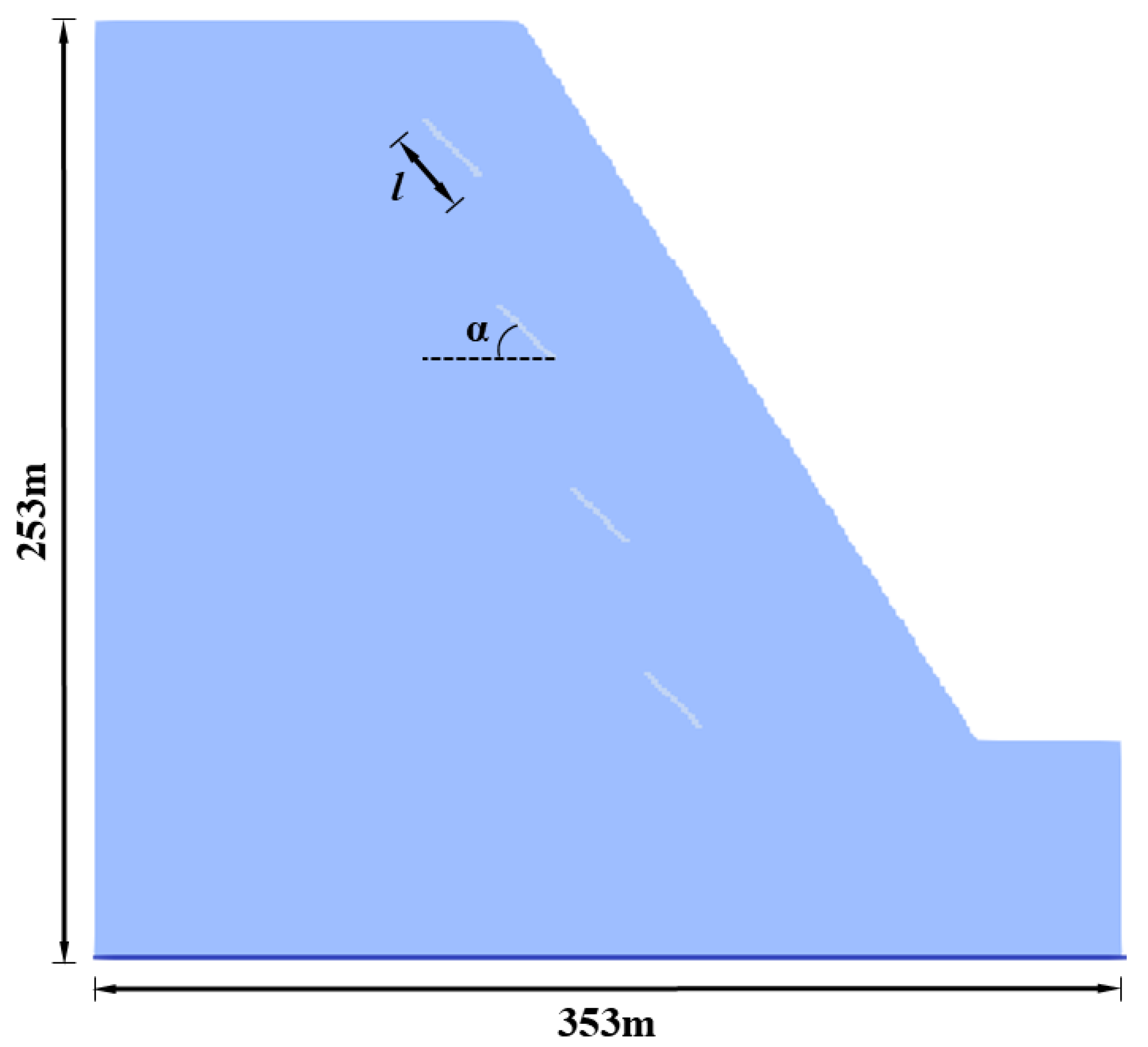
Figure 2 presents the dimensions of the numerical model in this study, which is a typical two-dimensional slope profile simplified from an actual engineering profile. The slope has a length of 353 m and a height of 253 m, with regularly arranged fissures inside. The length of the fissure is defined as l, and the inclination angle with respect to the horizontal direction is defined as α. The parameters of the model are set as follows: elastic modulus E = 17 GPa, tensile strength σt = 2 MPa, and Poisson’s ratio μ = 0.2. The F-T cycles are applied to the slope, and the bottom is the fixed boundary.
The validation of the method has been illustrated in reference [5], and the sensitivity to SPH particle spacing has been detailly discussed in reference [27]. Visual Studio is used to perform the SPH simulation. To investigate the effects of different fissure lengths, quantities, inclination angles, and rows on the frost heave failure mode of rock slopes, the following calculation schemes are set up: Scheme A for different fissure lengths l; Scheme B for different fissure quantities n; Scheme C for different fissure inclination angles α; and Scheme D for different fissure rows p. The specific calculation schemes are shown in Table 2.

4.2. Influence of Different Fissure Lengths on Slope Frost Heave Failure

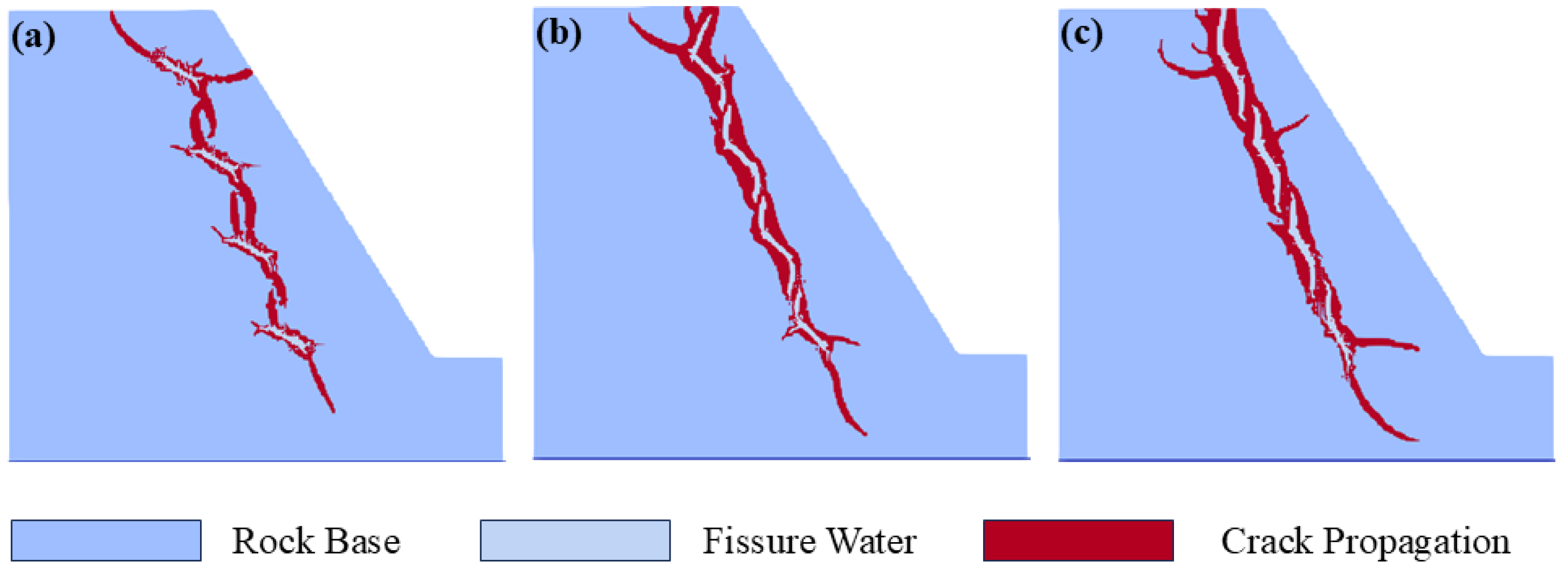
Figure 3 shows the influence of different fissure lengths on slope frost heave failure under the condition that the number of fissures, fissure inclination angle, and number of fissure rows are kept constant. It can be seen from the figure that different fissure lengths have a significant impact on the morphological characteristics and development trends of fissures during slope frost heave failure. For the fissure length l = 20 m, the tensile stress develops from both ends of the initial fissure, and the initial fissures show a mutual “attraction” phenomenon, causing the secondary fissures to deviate from the direction of the initial fissures and overlap with each other. In this case, each fissure can be approximately regarded as being in the same straight line. Finally, the frost heave failure of the slope develops roughly along this straight line, and the frost heave failure fissures are distributed in a strip shape, with the failure penetrating to the top of the model. For the fissure length l = 40 m, the secondary fissures develop from both ends of the initial fissures, and the initial fissures show a mutual “attraction” phenomenon, causing the secondary fissures to deviate from the direction of the initial fissures and overlap with each other. Compared with the fissure length l = 20 m, the overlapping position of the secondary fissures and the initial fissures tends to develop toward the center of the initial fissures when the fissure length is l = 40 m. Finally, the frost heave failure of the slope generally develops along the direction of the initial fissures, but the secondary fissures also affect the frost heave failure of the slope, and the frost heave failure fissures are distributed in a tree-like shape, with the scale of frost heave failure increasing and the failure penetrating to the top of the model. For the fissure length l = 60 m, the secondary fissures develop from both ends of the initial fissures, and the initial fissures show a mutual “attraction” phenomenon, causing the secondary fissures to deviate from the direction of the initial fissures and overlap with each other. Compared with the previous two groups, when the fissure length is l = 60 m, the overlapping position of the secondary fissures and the initial fissures is close to the center of the initial fissures. Finally, the frost heave failure of the slope develops significantly in both the direction of the initial fissures and the direction of the secondary fissures, and the frost heave failure fissures are distributed in a tree-like shape, with the scale of frost heave failure increasing significantly and the frost heave fissures penetrating the model.

4.3. Influence of Different Numbers of Fissures on Slope Frost Heave Failure

Figure 4 shows the influence of different numbers of fissures on slope frost heave failure under the condition that the fissure length, fissure inclination angle, and number of fissure rows are kept constant. It can be seen from the figure that different numbers of fissures have a significant impact on the morphological characteristics and development trend of fissures during slope frost heave failure. For the number of fissures n = 2, the secondary fissures develop from both ends of the initial fissures, and the initial fissures show a mutual “attraction” phenomenon, causing the secondary fissures to deviate from the direction of the initial fissures. However, due to the large distance between the fissures, they do not overlap with each other. Finally, the frost heave failure of the slope develops independently along the two initial fissures, and the frost heave failure fissures are distributed in a sword-like shape, with the failure not penetrating to the top of the model. For the number of fissures n = 4, the secondary fissures develop from both ends of the initial fissures, and the initial fissures show a mutual “attraction” phenomenon, causing the secondary fissures to deviate from the direction of the initial fissures. Compared with the number of fissures n = 2, due to the reduced distance between the fissures, they overlap with each other. In this case, each fissure can be approximately regarded as being in the same straight line. Finally, the frost heave failure of the slope develops roughly along this straight line, and the frost heave failure fissures are distributed in a strip shape, with the failure penetrating to the top of the model. For the number of fissures n = 7, the secondary fissures develop from both ends of the initial fissures, and the initial fissures show a mutual “attraction” phenomenon, causing the secondary fissures to deviate from the direction of the initial fissures. Compared with the previous two groups, due to the continuous reduction of the distance between the fissures, the secondary fissures overlap with each other in the early stage of frost heave failure, and the overlapping becomes closer in the middle and late stages of frost heave failure. Finally, the frost heave failure of the slope generally develops along the direction of the initial fissures, but due to the closer overlapping of the secondary fissures, the secondary fissures also affect the frost heave failure of the slope, and the frost heave failure fissures are distributed in a tree-like shape, with the scale of frost heave failure increasing and the failure penetrating to the top of the model.

4.4. Influence of Different Fissure Inclination Angles on Slope Frost Heave Failure

Figure 5 shows the influence of different fissure inclination angles on slope frost heave failure under the condition that the fissure length, number of fissures, and number of fissure rows are kept constant. It can be seen from the figure that different fissure inclination angles have a significant impact on the morphological characteristics and development trend of fissures during slope frost heave failure. For the fissure inclination angle α = 30°, the secondary fissures develop from both ends of the initial fissures, and the initial fissures show a mutual “attraction” phenomenon, causing the secondary fissures to deviate from the direction of the initial fissures and overlap with each other. Finally, the frost heave failure of the slope generally develops along the direction of the initial fissures, but the secondary fissures also affect the frost heave failure of the slope, and the frost heave failure fissures are distributed in a fishbone-like shape, with the failure penetrating to the top of the model. For the fissure inclination angle α = 45°, the secondary fissures develop from both ends of the initial fissures, and the initial fissures show a mutual “attraction” phenomenon, causing the secondary fissures to deviate from the direction of the initial fissures and overlap with each other. Compared with the fissure inclination angle α = 30°, due to the larger fissure inclination angle, each fissure can be approximately regarded as being in the same straight line, and the overlapping between the fissures is closer. Finally, the frost heave failure of the slope develops roughly along this straight line, and the frost heave failure fissures are distributed in a strip shape, with the scale of frost heave failure increasing and the failure penetrating to the top of the model. For the fissure inclination angle α = 60°, the secondary fissures develop from both ends of the initial fissures, and the initial fissures show a mutual “attraction” phenomenon, causing the secondary fissures to deviate from the direction of the initial fissures and overlap with each other. Compared with the previous two groups, due to the continuous increase of the fissure inclination angle, each fissure is almost in the same straight line, and the overlapping between the fissures is closer. Finally, the frost heave failure of the slope develops roughly along this straight line, and the frost heave failure fissures are distributed in a strip shape, with the scale of frost heave failure increasing and the failure penetrating to the top of the model.

4.5. Influence of Different Numbers of Fissure Rows on Rock Slope Frost Heave Failure

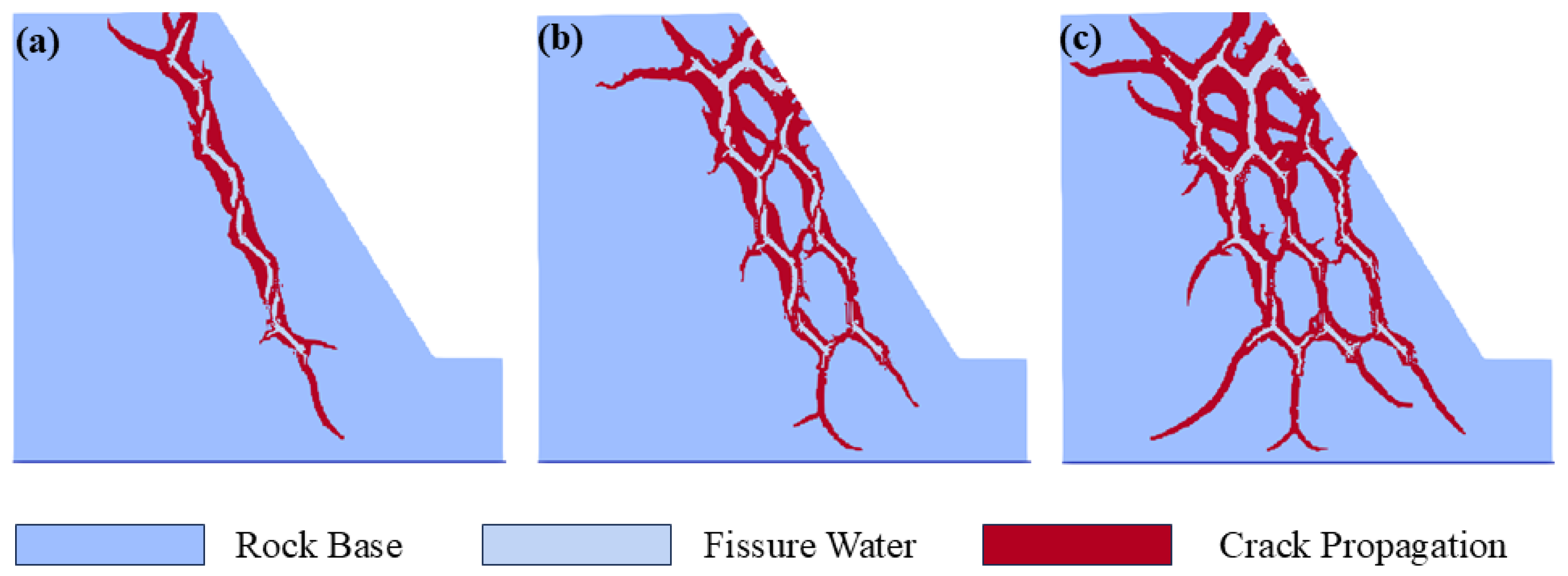
Figure 6 shows the influence of different numbers of fissure rows on slope frost heave failure under the condition that the fissure length, number of fissures, and fissure inclination angle are kept constant. It can be seen from the figure that different numbers of fissure rows have a significant impact on the morphological characteristics and development trend of fissures during slope frost heave failure. For the number of fissure rows p = 1, the secondary fissures develop from both ends of the initial fissures, and the initial fissures show a mutual “attraction” phenomenon, causing the secondary fissures to deviate from the direction of the initial fissures and overlap with each other. In this case, each fissure can be approximately regarded as being in the same straight line. Finally, the frost heave failure of the slope develops roughly along this straight line, and the frost heave failure fissures are distributed in a strip shape, with the failure penetrating to the top of the model. For the number of fissure rows p = 2, the secondary fissures develop from both ends of the initial fissures, and the initial fissures show a mutual “attraction” phenomenon, causing the secondary fissures to deviate from the direction of the initial fissures and overlap with each other. Compared with the number of fissure rows p = 1, the secondary fissures derived from the number of fissure rows p = 2 are more likely to contact the slope, and the influence of the secondary fissures increases significantly. Finally, the frost heave failure of the slope develops along the direction of the initial fissures and the direction of the secondary fissures, and the frost heave failure fissures are distributed in a network shape, with the scale of frost heave failure increasing and the failure penetrating to the slope. For the number of fissure rows p = 3, the secondary fissures develop from both ends of the initial fissures, and the initial fissures show a mutual “attraction” phenomenon, causing the secondary fissures to deviate from the direction of the initial fissures and overlap with each other. Compared with the previous two groups, due to the continuous increase in the number of fissure rows, the secondary fissures derived from the number of fissure rows p = 3 are more likely to contact the slope, and the influence of the secondary fissures increases significantly. Finally, the frost heave failure of the slope develops along the direction of the initial fissures and the direction of the secondary fissures, and the frost heave failure fissures are distributed in a network shape, with the scale of frost heave failure increasing significantly and the failure penetrating to the slope and the top of the model.

5. Discussions

5.1. Mechanism of Action of Different Fissure Lengths on Slope Frost Heave Failure

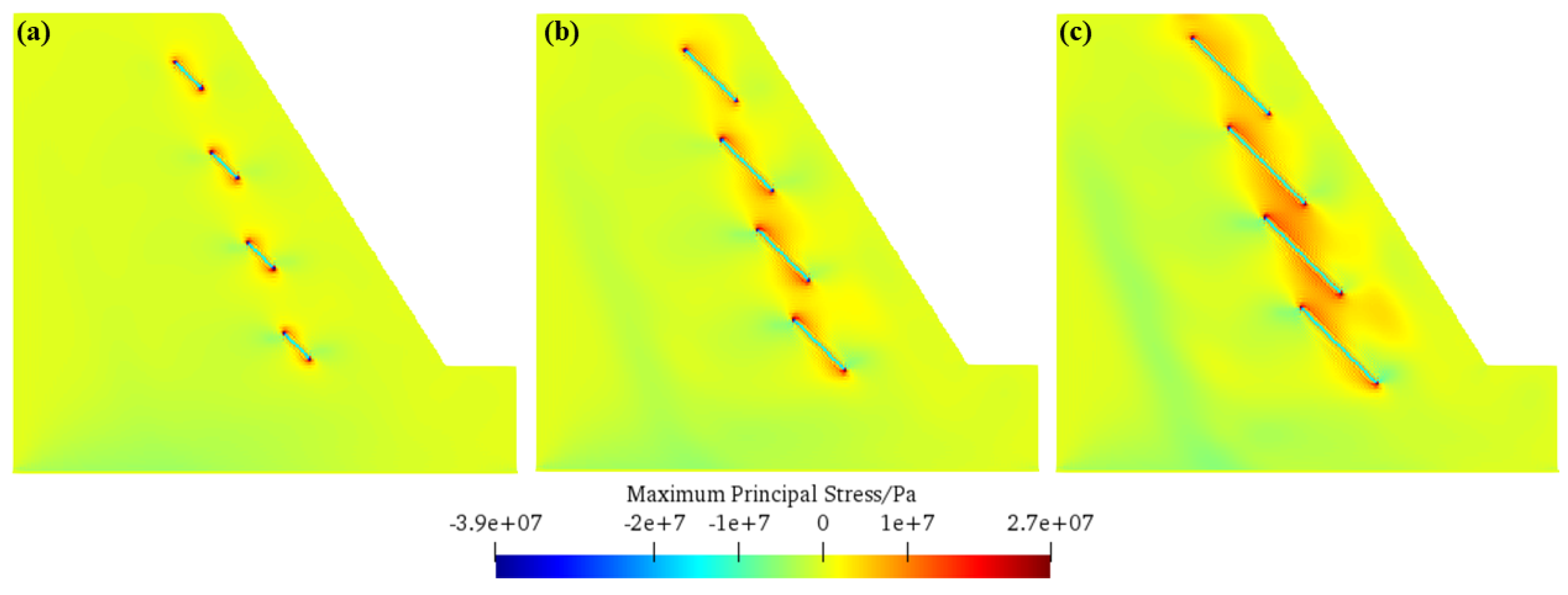
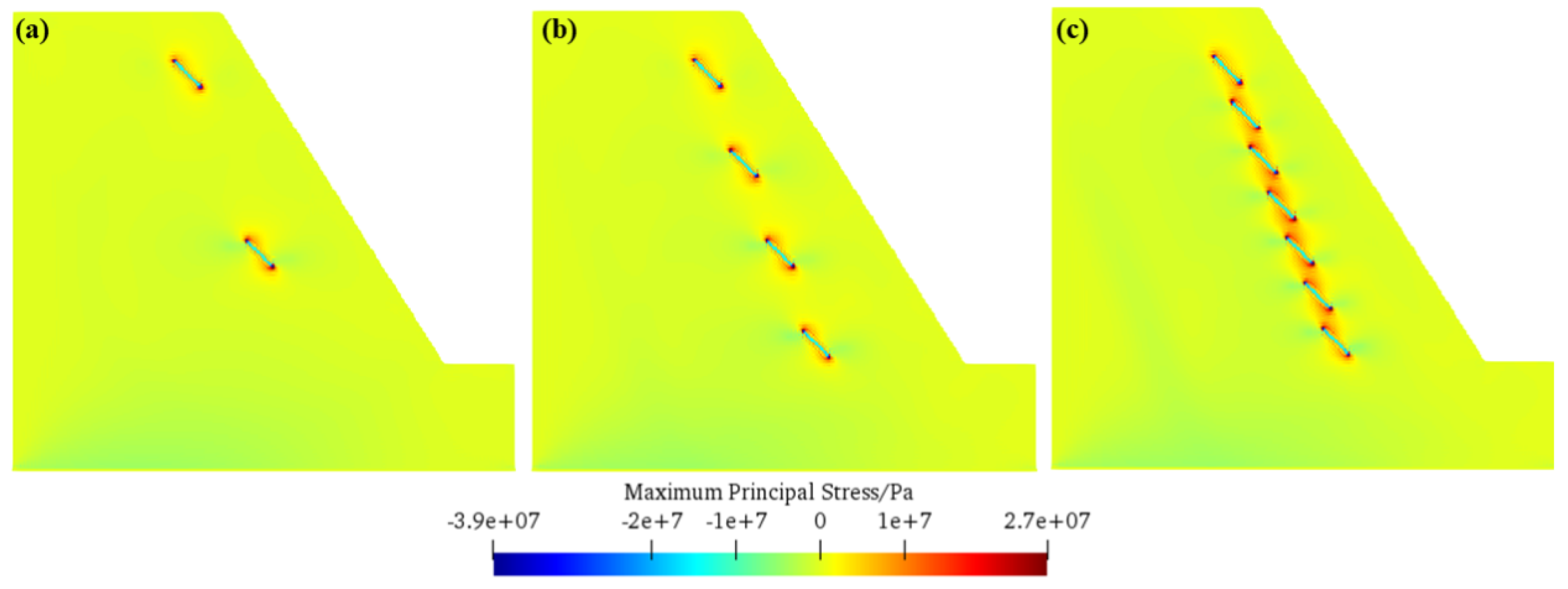
Figure 7 presents the distribution law of the maximum principal stress of the slope under different fissure lengths. As can be seen from Figure 7, when the fissure length is small (e.g., l = 20 m), the phenomenon of tensile stress concentration is mainly confined to the tip of the prefabricated fissure and has not yet formed a contiguous distribution. This is consistent with the observation in Section 4.2, where secondary cracks develop from both ends of the initial fissures, and although there is a tendency for mutual “attraction” between the initial fissures, causing the secondary cracks to deviate from their initial directions and overlap with each other, the overall failure cracks are distributed in a strip shape, with the failure penetrating to the top of the model. As the fissure length increases (e.g., l = 40 m and l = 60 m), the tensile stress concentration areas gradually connect into a contiguous region between the fissures. This change leads to significant alterations in the morphological characteristics and development trend of the cracks during the frost heave failure process. When the fissure length is 40 m, the overlapping position of the secondary cracks and the initial fissures develops toward the center of the initial fissures, and the frost heave failure generally develops along the direction of the initial fissures, while the direction of the secondary cracks also affects the failure, resulting in failure cracks distributed in a tree-like shape with an increased scale. When the fissure length reaches 60 m, the overlapping position of the secondary cracks and the initial fissures is closer to the center of the initial fissures, and the failure in both the direction of the initial fissures and the direction of the secondary cracks develops significantly, with the frost heave failure cracks showing a tree-like distribution, the scale further increasing significantly, and the failure penetrating the model. This indicates that with the increase in fissure length, the contiguous distribution of tensile stress concentration areas exacerbates the interaction between fissures, promotes the development and overlapping of secondary cracks, and thus leads to the expansion of the scale of slope frost heave failure and the complexity of failure morphology.

5.2. Mechanism of Action of Different Numbers of Fissures on Slope Frost Heave Failure

Figure 8 shows the distribution law of the maximum principal stress of the slope under different numbers of fissures. It can be observed from Figure 8 that when the number of fissures is small (e.g., n = 2), the tensile stress concentration phenomenon mainly occurs at the tip of the prefabricated fissures and has not formed a contiguous distribution. This is consistent with the observation in Section 4.3, where secondary cracks develop from both ends of the initial fissures, and although there is a tendency for mutual “attraction” between the initial fissures causing the secondary cracks to deviate from their initial directions, due to the large distance between the fissures, the secondary cracks do not overlap with each other, and the frost heave failure of the slope develops independently along the two initial fissures, with the failure cracks distributed in a sword-like shape and not penetrating the top of the model. As the number of fissures increases (e.g., n = 4 and n = 7), the tensile stress concentration areas gradually connect into a contiguous region between the fissures. When the number of fissures is four, due to the reduced distance between the fissures, the secondary cracks overlap with each other, and each crack is approximately in the same straight line, so the slope frost heave failure develops along this straight line, with the failure cracks distributed in a strip shape and penetrating the top of the model. When the number of fissures reaches seven, the distance between the fissures is further reduced, and the secondary cracks overlap with each other in the early stage of frost heave failure, and the overlapping becomes closer in the middle and late stages. The frost heave failure of the slope develops significantly in both the direction of the initial fissures and the direction of the secondary cracks, with the failure cracks distributed in a tree-like shape, the scale increasing, and the failure penetrating the top of the model. This indicates that the increase in the number of fissures enhances the interaction between the fissures, accelerates the overlapping and expansion of the cracks, and thus leads to the expansion of the scale of slope frost heave failure and the complexity of failure morphology.

5.3. Mechanism of Action of Different Fissure Inclination Angles on Slope Frost Heave Failure

Figure 9 illustrates the distribution law of the maximum principal stress of the slope under different fissure inclination angles. As can be seen from Figure 9, when the fissure inclination angle is small (e.g., α = 30°), the tensile stress concentration area is mainly distributed in a region near the tip of the prefabricated fissure, showing a relatively dispersed distribution characteristic. This is consistent with the observation in Section 4.4, where secondary cracks develop from both ends of the initial fissures, and the mutual “attraction” between the initial fissures causes the secondary cracks to deviate from their initial directions and overlap with each other, resulting in the frost heave failure of the slope developing in both the direction of the initial fissures and the direction of the secondary cracks, with the failure cracks distributed in a fishbone-like shape and penetrating the top of the model. As the fissure inclination angle increases (e.g., α = 45° and α = 60°), the tensile stress concentration area gradually converges and is only confined to the tip of the fissure. When the fissure inclination angle is 45°, due to the increase in the fissure inclination angle, each crack is approximately in the same straight line and the overlapping is closer, so the slope frost heave failure develops along this straight line, with the failure cracks distributed in a strip shape and the scale increasing. When the fissure inclination angle reaches 60°, the continuous increase in the fissure inclination angle makes each crack almost in the same straight line, and the overlapping of cracks is closer, and the slope frost heave failure still develops along this straight line, with the failure cracks distributed in a strip shape, the scale further increasing, and the failure penetrating the top of the model. This indicates that as the fissure inclination angle increases, the tensile stress concentration area gradually converges from a dispersed distribution to the fissure tip, changing the interaction mode between the fissures, thereby affecting the development direction and overlapping tightness of the secondary cracks, leading to the transformation of the slope frost heave failure morphology from fishbone-like to strip-like, and the failure scale expands with the increase in the inclination angle.

5.4. Mechanism of Action of Different Numbers of Fissure Rows on Rock Slope Frost Heave Failure

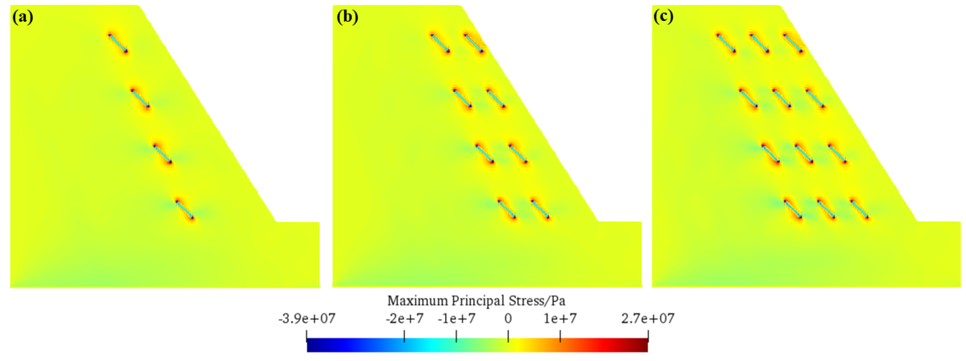
Figure 10 displays the distribution law of the maximum principal stress of the slope under different numbers of fissure rows. It can be seen from Figure 10 that when the number of fissure rows is small (e.g., p = 1), the tensile stress concentration area extends along the direction of the single row of fissures, connecting the fissure tips in the single row into a contiguous stress concentration zone. This is consistent with the observation in Section 4.5, where secondary cracks develop from both ends of the initial fissures and overlap with each other, the single row of fissures is approximately in the same straight line, and the slope frost heave failure develops along this straight line, with the failure cracks distributed in a strip shape and penetrating the top of the model. As the number of fissure rows increases (e.g., p = 2 and p = 3), the tensile stress concentration area forms a more complex contiguous distribution between the multiple rows of fissures. When the number of fissure rows is two, the secondary cracks derived from the multiple rows of fissures are more likely to contact the slope, and the tensile stress concentration area forms a network connection across the row spacing, so the slope frost heave failure develops simultaneously in the direction of the initial fissures and the direction of the secondary cracks, with the failure cracks distributed in a network shape and the scale increasing. When the number of fissure rows reaches three, the continuous increase in the number of rows makes the tensile stress concentration area form a more dense contiguous network between the multiple rows of fissures, the probability of the secondary cracks contacting the slope increases significantly, and the slope frost heave failure develops comprehensively along the direction of the multiple rows of fissures and the direction of the secondary cracks, with the failure cracks distributed in a network shape, the scale increasing significantly, and the failure penetrating the top of the model. This indicates that as the number of fissure rows increases, the tensile stress concentration area transforms from a single-row continuous distribution to a multi-row network-like contiguous distribution, strengthening the interaction between the inter-row fissures, promoting the collaborative development and spatial overlapping of the multi-row secondary cracks, and thus leading to the evolution of the slope frost heave failure morphology from strip-like to network-like, and the failure scale expands sharply with the increase in the number of rows.

5.5. Application Prospects of SPH into Simulating Rock Frost Cracking

The application of the Smoothed Particle Hydrodynamics (SPH) method in simulating rock frost cracking not only addresses the technical bottlenecks of traditional numerical approaches (e.g., finite element method (FEM), discrete element method (DEM)) in this field but also provides unique new insights that supplement and advance the understanding of frost heave failure mechanisms in water-saturated fissured rock slopes. These advantages, rooted in the intrinsic characteristics of the SPH method, open up broad application prospects for solving complex engineering problems in cold-region geotechnical engineering.
Compared with FEM [28,29], which has long been used in freeze–thaw multi-field coupling simulation of fissured rocks, the SPH method breaks through the limitations of grid-dependent discretization and provides critical new insights into the randomness and suddenness of crack propagation under frost heave. As noted in Section 1, FEM often requires predefined crack propagation paths or frequent grid reconstruction when handling dynamic crack evolution. This artificial intervention not only increases computational complexity but also imposes subjective assumptions on crack trajectories—for example, FEM simulations of frost heave failure typically assume linear or pre-estimated branching paths, which fail to reflect the real-world scenario where cracks initiate at arbitrary weak points (e.g., micro-fissures in rock matrices) and propagate unpredictably under non-uniform frost heave forces. In contrast, the fully meshless nature of SPH (Section 2.1) discretizes rock masses into particles carrying physical quantities (mass, momentum, energy), allowing natural simulation of crack initiation at any particle with stress exceeding tensile strength (Section 3.1) and spontaneous branching/coalescence driven by local stress redistribution. For instance, in the simulation of long fissures (l = 60 m, Figure 3c), SPH captures the unexpected “tree-like” crack network that forms when secondary cracks deviate from initial fissure directions and interconnect at non-predetermined points—a phenomenon that FEM would struggle to reproduce without artificial path adjustment. This insight reveals that frost heave failure is not a linear, path-dependent process but a complex, spatially heterogeneous evolution, which corrects the simplification of crack behavior in FEM-based studies.
Relative to DEM, which treats rock masses as aggregates of independent contact units, the SPH method offers new insights into the multi-physics coupling mechanism of frost heave by avoiding complex mesoscale parameter calibration and enabling more accurate integration of thermodynamic and mechanical behaviors. As highlighted in Table 1, DEM relies on numerous mesoscale parameters (e.g., particle contact stiffness, friction coefficient) that require labor-intensive calibration against experimental data—this calibration process often introduces uncertainties, especially for heterogeneous rock masses with random fissure distributions. Moreover, DEM simulations of frost heave typically simplify phase transition as a volume expansion of discrete units, failing to fully couple the dynamic evolution of fissure water states (water, ice–water mixed, ice) with stress field changes. The SPH model developed in this study (Section 3.2) addresses this gap by integrating thermodynamic phase transition theory directly into particle dynamics: fissure water is classified into three particle types based on temperature (T > 0 °C for water, −20 °C < T < 0 °C for ice–water mixture, T < −20 °C for ice), and the equivalent thermal expansion coefficient method quantifies frost heave force as a temperature-dependent mechanical effect on particle interactions. This coupling allows SPH to reveal that frost heave force is not a uniform load but a dynamic, phase-dependent variable—for example, ice–water mixed particles (−20 °C < T < 0 °C) generate gradual frost heave (Equation (11)) that induces incremental crack propagation, while ice particles (T < −20 °C) trigger sudden stress spikes that accelerate crack coalescence. This insight, unattainable with DEM’s simplified phase transition model, clarifies the temporal heterogeneity of frost heave failure and explains why slope instability often occurs in discrete “bursts” during severe freezing periods.

6. Conclusions

This study targets the frost heave failure issue of water-saturated fissured rock slopes in global cold regions and seasonal frozen soil areas—an urgent problem restricting the construction and operation safety of major infrastructure such as China’s Sichuan–Tibet Railway and Qinghai–Tibet Railway. By developing a smoothed particle hydrodynamics (SPH)-based meshless numerical model and conducting systematic simulations on fissure geometric parameters, this research clarifies key mechanisms, supplements technical gaps, and provides engineering references. The specific conclusions are as follows:
(1)
An innovative SPH-based numerical model for simulating the full process of fissured rock mass frost heave failure has been developed. Aiming at the limitations of traditional numerical methods (e.g., finite element method requiring pre-defined crack paths, discrete element method needing complex parameter calibration), this model integrates the maximum tensile stress criterion as the particle failure criterion and uses a binary fracture marker (ξ) to dynamically characterize the particle failure state (ξ = 0 for failure, ξ = 1 for intact). Combined with thermodynamic phase transition theory, fissure water is classified into water particles (T > 0 °C), ice–water mixed particles (−20 °C < T < 0 °C), and ice particles (T < −20 °C); the equivalent thermal expansion coefficient method is further adopted to quantify the frost heave force on fissure surfaces. This model avoids grid distortion and artificial crack path assumptions, enabling natural simulation of random and sudden crack initiation, propagation, and coalescence under frost heave, which fills the gap in the application of the SPH method in the rock slope frost heave failure simulation mentioned in the document.
(2)
The influence law and mechanism of fissure length on slope frost heave failure have been clarified. When the fissure length is small (e.g., 20 m), tensile stress is concentrated only at the tip of prefabricated fissures, secondary cracks develop from both ends of initial fissures and overlap slightly, and the failure mode presents a “strip-like” distribution. As the length increases to 40 m and 60 m, tensile stress concentration areas between fissures gradually connect into a contiguous region, the overlapping position of secondary cracks and initial fissures shifts toward the center of fissures, and the failure mode transforms into “tree-like”. This indicates that the increase in fissure length intensifies the interaction between fissures, promotes the development and coalescence of secondary cracks, and significantly expands the failure scale.
(3)
The regulatory effect of fissure number on slope frost heave failure mode and scale has been determined. With a small number of fissures (e.g., 2), the distance between fissures is large, secondary cracks do not overlap, and failure develops independently along each initial fissure in a “sword-like” pattern without penetrating the slope top. When the number increases to four, reduced fissure spacing leads to secondary crack overlap, and failure develops along a quasi-straight line in a “strip-like” pattern with the failure penetrating the slope top. When the number reaches seven, secondary cracks overlap in the early stage of frost heave failure, and the failure mode transforms into “tree-like”. This confirms that the increase in fissure number strengthens the mutual influence between fissures, accelerates crack coalescence, and further expands the failure scale.
(4)
The relationship between fissure inclination angle and slope frost heave failure morphology has been revealed. For a small inclination angle (e.g., 30°), tensile stress concentration areas near fissure tips are dispersed, and secondary cracks deviate from initial fissure directions and form multi-branch structures, resulting in a “fishbone-shaped” failure mode with nine secondary cracks. As the inclination angle increases to 45° and 60°, tensile stress concentration areas converge to fissure tips; each fissure is approximately in the same straight line; the failure mode transforms into “strip-like”; and the number of secondary cracks decreases to four and three, respectively. This shows that the increase in fissure inclination angle changes the distribution of tensile stress concentration areas, thereby altering the development direction of secondary cracks and the final failure morphology.
(5)
The law of fissure row number affecting the spatial expansion of slope frost heave failure has been supplemented. With a single row of fissures, tensile stress concentration areas connect the tips of a single row of fissures into a continuous zone, and failure presents a “strip-like” distribution. When the row number increases to two, tensile stress concentration areas form a network connection between rows, secondary cracks are more likely to contact the slope surface, the failure mode evolves into “network-like”, and the failure area ratio rises to 12.7%. When the row number reaches three, the network of tensile stress concentration areas becomes denser, the probability of secondary cracks contacting the slope and slope top increases significantly, and the failure scale expands sharply. This indicates that the increase in fissure row number strengthens the interaction between inter-row fissures, promotes the collaborative development of multi-row secondary cracks, and leads to the evolution of failure morphology from “strip-like” to “network-like”.

Author Contributions

Investigation, C.G., F.Z., H.S., W.Z., B.Z., W.L. and S.Y.; writing—original draft, C.G., F.Z., H.S. and W.Z. All authors have read and agreed to the published version of the manuscript.

Funding

This research was financially supported by the National Natural Science Foundation of China (52409162).

Data Availability Statement

The raw data supporting the conclusions of this article will be made available by the authors on request.

Conflicts of Interest

Authors Feixiang Zeng and Han Shao were employed by the company PowerChina Guiyang Engineering Corporation Limited. The remaining authors declare that the research was conducted in the absence of any commercial or financial relationships that could be construed as a potential conflict of interest.

References

  1. Sun, L.; Shi, W.; Tian, X.; Li, J.; Zhao, B.; Wang, S.; Tan, J. A plane stress measurement method for CFRP material based on array LCR waves. NDT E Int. 2025, 151, 103318. [Google Scholar] [CrossRef]
  2. Wang, X.; Li, J.; Zhao, X.; Liang, Y. Propagation characteristics and prediction of blast-induced vibration on closely spaced rock tunnels. Tunn. Undergr. Space Technol. 2022, 123, 104416. [Google Scholar] [CrossRef]
  3. Wang, X.; Li, Z.; Li, W.; He, C.; Wang, Z. Analysis and prediction of dynamic stress concentration in jointed coal using boundary element method. Theor. Appl. Fract. Mech. 2025, 140, 105136. [Google Scholar] [CrossRef]
  4. Xiao, W. Analytical theory on instability sliding of surrounding rock blocks in tunnel roof under stress wave actions. Chin. J. Theor. Appl. Mech. 2024, 56, 183–197. [Google Scholar]
  5. Yu, S.; Ren, X.; Zhang, J. Modeling the rock frost cracking processes using an improved ice—Stress-Damage coupling method. Theor. Appl. Fract. Mech. 2024, 131, 104421. [Google Scholar] [CrossRef]
  6. Wang, X.; Zhang, X.; Li, W.; Jiang, Y.; Li, Z.; Wang, C. Analytical theoretical study on ultra-low friction characteristics of coal rock interfaces under stress wave action. J. China Coal Soc. 2024, 49, 4495–4507. [Google Scholar]
  7. Tang, J.; Zhang, M.; Guo, X. Investigation of creep and transport mechanisms of CO2 fracturing within natural gas hydrates. Energy 2024, 300, 131214. [Google Scholar] [CrossRef]
  8. Zhang, Z.; Tang, J.; Zhang, J. Modeling of scale-dependent perforation geometrical fracture growth in naturally layered media. Eng. Geol. 2024, 336, 107499. [Google Scholar] [CrossRef]
  9. Zhang, Z.; Tang, J.; Fan, B. An intelligent lithology recognition system for continental shale by using digital coring images and convolutional neural networks. Geoenergy Sci. Eng. 2024, 239, 212909. [Google Scholar] [CrossRef]
  10. Tang, L.Y.; Wu, D.N.; Zheng, J.G.; Ding, B.; Xu, P.Z.; Yu, Y.T.; Jia, H.L.; Li, H.B.; Qiu, P.Y. A nonlinear viscoelastic-plastic creep constitutive model of soil-rock mixture-concrete interface under freeze-thaw cycles. Res. Cold Arid Reg. 2025; in press. [Google Scholar] [CrossRef]
  11. Liang, X.; Liu, Z.; Peng, K.; Wang, H.; Zhang, S.; Yuan, C. Failure prediction of fissured rock under freeze-thaw cycles based on critical slowing down theory of acoustic emission multi-parameter. Results Eng. 2025, 5, 103874. [Google Scholar] [CrossRef]
  12. Chen, Y.; Lin, H.; Liang, L. Freeze-thaw failure characteristics and strength loss of non-penetrating fractured rock mass with different fracture densities. Theor. Appl. Fract. Mech. 2023, 124, 103792. [Google Scholar] [CrossRef]
  13. Zhou, Z.; Ullah, B.; Rui, Y.; Cai, X.; Lu, J. Predicting the failure of different rocks subjected to freeze-thaw weathering using critical slowing down theory on acoustic emission characteristics. Eng. Geol. 2023, 316, 107059. [Google Scholar] [CrossRef]
  14. Yu, M.; Wang, Z.; Xu, Y.; Wang, Y.; Wang, L.; Wen, J. Study on mechanical properties and energy evolution characteristics of excavation unloading rock under freeze–thaw temperature range. Eng. Fract. Mech. 2025, 325, 111293. [Google Scholar] [CrossRef]
  15. Zhang, J.; Du, R.; Zhang, X.; Huang, Z.; Zhang, W. The deformation and failure characteristics of tunnels in layered rock with gentle dip angles after freeze–thaw cycles: Physical model tests and numerical investigation. Tunn. Undergr. Space Technol. Inc. Trenchless Technol. Res. 2024, 144, 105527. [Google Scholar] [CrossRef]
  16. Zhang, J.; Guo, L. A fully coupled thermo-mechanical peridynamic model for cracking analysis of frozen rocks. Comput. Geotech. 2023, 164, 105809. [Google Scholar] [CrossRef]
  17. Guo, L.; Ma, G.; Chen, G. A micro frost heave model for porous rock considering pore characteristics and water saturation. Comput. Geotech. 2024, 166, 106029. [Google Scholar] [CrossRef]
  18. Deng, Z.; Zhang, X.; Wang, Z.; Min, J.; Wei, J. Analysis of fracture toughness deterioration and instability model of dangerous rock masses under freeze–thaw cycles. Theor. Appl. Fract. Mech. 2024, 131, 104398. [Google Scholar] [CrossRef]
  19. Sun, L.; Tang, X.; Zeeman, B. Numerical investigation of the path-dependent frost heave process in frozen rock under different freezing conditions. J. Rock Mech. Geotech. Eng. 2025, 17, 637–651. [Google Scholar] [CrossRef]
  20. Zhou, Y.; Tan, X.; Yang, D. A numerical method to consider the interaction between multiple fractures in frozen rocks based on XFEM. Comput. Geotech. 2024, 169, 106240. [Google Scholar] [CrossRef]
  21. Zhao, Y.; Zhao, Q.; Yang, T.; Chen, Y.; Zhang, P.; Liu, H. Investigation of crack propagation and acoustic emission characteristics in jointed rock under freeze–thaw cycles based on DEM. Int. J. Min. Sci. Technol. 2025, 35, 1171–1195. [Google Scholar] [CrossRef]
  22. Qiu, L.; Shi, C.; Zhang, L.; Zhang, F. Study on meso-deformation and failure mechanism of rock mass with micro-cracks under freeze-thaw loading. Simul. Model. Pract. Theory 2024, 135, 102974. [Google Scholar] [CrossRef]
  23. Shen, F.; Qiu, W.; Xie, K.; Xing, M.; Zhu, H.; Huang, S. A discrete element-based study of freeze–thaw damage in water-filled fractured rock. Comput. Geotech. 2025, 185, 107343. [Google Scholar] [CrossRef]
  24. Li, Z.; Liu, X.; Sun, Y.; Jiang, J.; He, Z. A study of the frost heave damage mechanism and numerical simulation of earth-rock dam slope protection in cold regions under the combined effects of moisture migration and ice loads. Cold Reg. Sci. Technol. 2025. [Google Scholar] [CrossRef]
  25. Li, K.; Li, Y.; Yin, F.; Dai, F.; Wang, C.; Zhang, S.; Wang, K. Mechanical properties and failure mechanism of rock-like specimens with arc-shaped flaws under freeze–thaw cycles. Theor. Appl. Fract. Mech. 2024, 130, 104275. [Google Scholar] [CrossRef]
  26. Liu, Q.; Kang, Y.; Liu, X. Analysis of stress field and coupling thermos-mechanical simulation of single-fracture freezed rock masses. Chin. J. Rock Mech. Eng. 2011, 30, 217–223. [Google Scholar]
  27. Yu, S.; Ren, X.; Zhang, J. An Improved Form of SPH Method for Simulating the Thermo-Mechanical-Damage Coupling Problems and Its Applications. Rock Mech. Rock Eng. 2022, 55, 1633–1648. [Google Scholar] [CrossRef]
  28. Zhang, W.; Xie, X.; Shi, D. Experimental insights into the mechanical properties and constitutive models of coral aggregate seawater concrete mixed with natural aggregates. J. Build. Eng. 2025, 107, 112756. [Google Scholar] [CrossRef]
  29. Zhang, W.; Li, H.; Shi, D. Determination of Safety Monitoring Indices for Roller-Compacted Concrete Dams Considering Seepage–Stress Coupling Effects. Mathematics 2023, 11, 3224. [Google Scholar] [CrossRef]
Figure 1. Schematic diagram of particle failure process under the SPH framework.
Water 17 02858 g001
Figure 2. Schematic diagram of the numerical model size.
Water 17 02858 g002
Figure 3. Influence of different fissure lengths on the process of slope frost heave failure. (a) l = 20 m; (b) l = 40 m; (c) l = 60 m.
Water 17 02858 g003
Figure 4. Influence of different numbers of fissures on the process of slope frost heave failure. (a) n = 2; (b) n = 4; (c) n = 7.
Water 17 02858 g004
Figure 5. Influence of different fissure inclination angles on the process of slope frost heave failure. (a) α = 30°; (b) α = 45°; (c) α = 60°.
Water 17 02858 g005
Figure 6. Influence of different numbers of fissure rows on the process of slope frost heave failure. (a) p = 1; (b) p = 2; (c) p = 3.
Water 17 02858 g006
Figure 7. Distribution law of maximum principal stress of slope under different fissure lengths. (a) l = 20 m; (b) l = 40 m; (c) l = 60 m.
Water 17 02858 g007
Figure 8. Distribution law of maximum principal stress of slope under different numbers of fissures. (a) n = 2; (b) n = 4; (c) n = 7.
Water 17 02858 g008
Figure 9. Distribution law of maximum principal stress of slope under different fissure inclination angles. (a) α = 30°; (b) α = 45°; (c) α = 60°.
Water 17 02858 g009
Figure 10. Distribution law of maximum principal stress of slope under different numbers of fissure rows. (a) p = 1; (b) p = 2; (c) p = 3.
Water 17 02858 g010
Table 1. Advantages and limitations of the numerical methods.
Numerical MethodsAdvantagesLimitations
FEM
  • High maturity, suitable for accurate calculation of linear elastic and small-deformation problems.
  • Can simulate the coupling of temperature field, seepage field, and stress field.
  • Relies on mesh division. When dealing with dynamic crack propagation, it is necessary to predefine crack propagation paths or frequently reconstruct meshes, which increases computational complexity.
  • Artificial assumptions are prone to introducing errors, making it difficult to reflect the randomness and suddenness of crack propagation in rocks under complex stress conditions.
DEM
  • Can naturally simulate dynamic processes such as crack initiation, propagation, and branching, truly reflecting the randomness of rock crack propagation.
  • Can synchronously simulate rock fragmentation and debris movement trajectories, suitable for analyzing nonlinear failure driven by frost heave forces.
  • Involves numerous mesoscale parameters (e.g., particle contact stiffness, friction coefficient), requiring a complex parameter calibration process.
  • High computational cost, limiting its application in large-scale models in engineering practice.
SPH
  • Fully meshless, avoiding mesh distortion under large deformations and efficiently handling extreme deformation scenarios such as rock fragmentation and crack branching.
  • No predefinition of crack paths is needed; random crack initiation and propagation can be flexibly captured through particle interpolation.
  • Intuitively describes energy transfer and dissipation under dynamic loads and can synchronously simulate crack propagation and rock block movement, adapting to the dynamic evolution of fissures driven by frost heave forces.
Table 2. Calculation schemes.
SchemesDetailsSchemesDetails
A1l = 20 mC1α = 30°
A2l = 40 mC2α = 45°
A3l = 60 mC3α = 60°
B1n = 2D1p = 1
B2n = 4D2p = 2
B3n = 7D3p = 3
Disclaimer/Publisher’s Note: The statements, opinions and data contained in all publications are solely those of the individual author(s) and contributor(s) and not of MDPI and/or the editor(s). MDPI and/or the editor(s) disclaim responsibility for any injury to people or property resulting from any ideas, methods, instructions or products referred to in the content.