Review

Continuous Electrocoagulation Processes for Industrial Inorganic Pollutants Removal: A Critical Review of Performance and Applications

by
Zakaria Al-Qodah
1,*,
Maha Mohammad AL-Rajabi
1,
Enshirah Da’na
1,
Mohammad Al-Shannag
2,
Khalid Bani-Melhem
3 and
Eman Assirey
4,*
1
Chemical Engineering Department, Faculty of Engineering Technology, Al-Balqa Applied University, Amman 11134, Jordan
2
Department of Chemical Engineering, School of Engineering, The University of Jordan, Amman 11942, Jordan
3
Water Technology Unit (WTU), Center for Advanced Materials (CAM), Qatar University, Doha P.O. Box 2713, Qatar
4
Chemistry Department, Faculty of Science, Taibah University, Madinah P.O. Box 41411, Saudi Arabia
*
Authors to whom correspondence should be addressed.
Water 2025, 17(17), 2639; https://doi.org/10.3390/w17172639
Submission received: 9 August 2025 / Revised: 29 August 2025 / Accepted: 3 September 2025 / Published: 6 September 2025
(This article belongs to the Special Issue Advanced Technologies in Water and Wastewater Treatment)

Abstract

This review provides a critical and technically grounded assessment of continuous electrocoagulation processes (CEPs) for the treatment of industrial inorganic pollutants, emphasizing recent innovations, methodological developments, and practical outcomes. A comprehensive literature survey indicates that 53 studies published over the past 25 years have investigated CEPs for inorganic contaminant removal, with 36 focusing on standalone electrocoagulation systems and 17 exploring integrated CEPs approaches. Recent advancements in reactor design, such as enhanced internal mixing, optimized electrode geometry, and modular configurations, have significantly improved treatment efficiency, scalability, and operational stability. Evidence indicates that CEPs can achieve high removal efficiencies for a wide range of inorganic contaminants, including fluoride, arsenic, heavy metals (e.g., chromium, lead, nickel, iron), nitrates, and phosphates, particularly under optimized operating conditions. Compared to conventional treatment methods, CEPs offer several advantages, such as simplified operation, reduced chemical consumption, lower sludge generation, and compatibility with renewable energy sources and complementary processes like membrane filtration, flotation, and advanced oxidation. Despite these promising outcomes, industrial-scale implementation remains constrained by non-standardized reactor designs, variable operational parameters, electrode passivation, high energy requirements, and limited long-term field data. Furthermore, few studies have addressed the modeling and optimization of integrated CEPs systems, highlighting critical research gaps for process enhancement and reliable scale-up. In conclusion, CEPs emerge as a novel, adaptable, and potentially sustainable approach to industrial inorganic wastewater treatment. Its future deployment will rely on continued technological refinement, standardization, validation under real-world conditions, and alignment with regulatory and economic frameworks.

1. Introduction

The exponential growth of industrialization over recent decades has significantly increased both the variety and quantity of conventional and emerging water contaminants [1]. These contaminants are generally classified as either organic or inorganic pollutants. Both categories of contaminants have a negative impact on the environment and human health. While organic pollutants have been extensively studied for years, with established methods for their detection and treatment [2,3], inorganic contaminants are now drawing increased attention due to their persistence, bioaccumulation potential, and toxicity [4]. For example, heavy metals like lead, mercury, cadmium, and arsenic do not degrade easily and can accumulate in soil, water, and living organisms, posing long-term environmental and health risks. Despite often occurring at very low or trace concentrations, inorganic pollutants are widespread and can be as toxic as organic pollutants when present in higher amounts [4].
Conventional water treatment methods, such as chemical precipitation, ion exchange [5,6], membrane filtration [7,8], adsorption [9,10,11], and biotechnological processes [12,13] have been widely employed to address inorganic contaminants removal. However, these techniques often suffer from limitations such as high operational costs, secondary pollution, sludge generation, and limited removal efficiencies for certain metal ions at low concentrations [14,15,16,17]. Therefore, finding cost-effective and eco-friendly wastewater treatment methods is always a concern for all researchers. In the last few years, electrochemical techniques have emerged as a promising treatment method for the remediation of both organic and inorganic pollutants [3,18,19]. These techniques are based on using electric current and electrodes to induce chemical reactions that lead to the removal or transformation of pollutants. Among these electrochemical methods, electrocoagulation (EC) has emerged as a promising treatment technology for the remediation of different types of pollutants [20,21]. The EC process is classified as an energy-efficient technique that is capable of removing a wide range of contaminants from municipal [22,23], industrial [24,25], and agricultural [26,27] wastewater streams, making it a versatile solution.
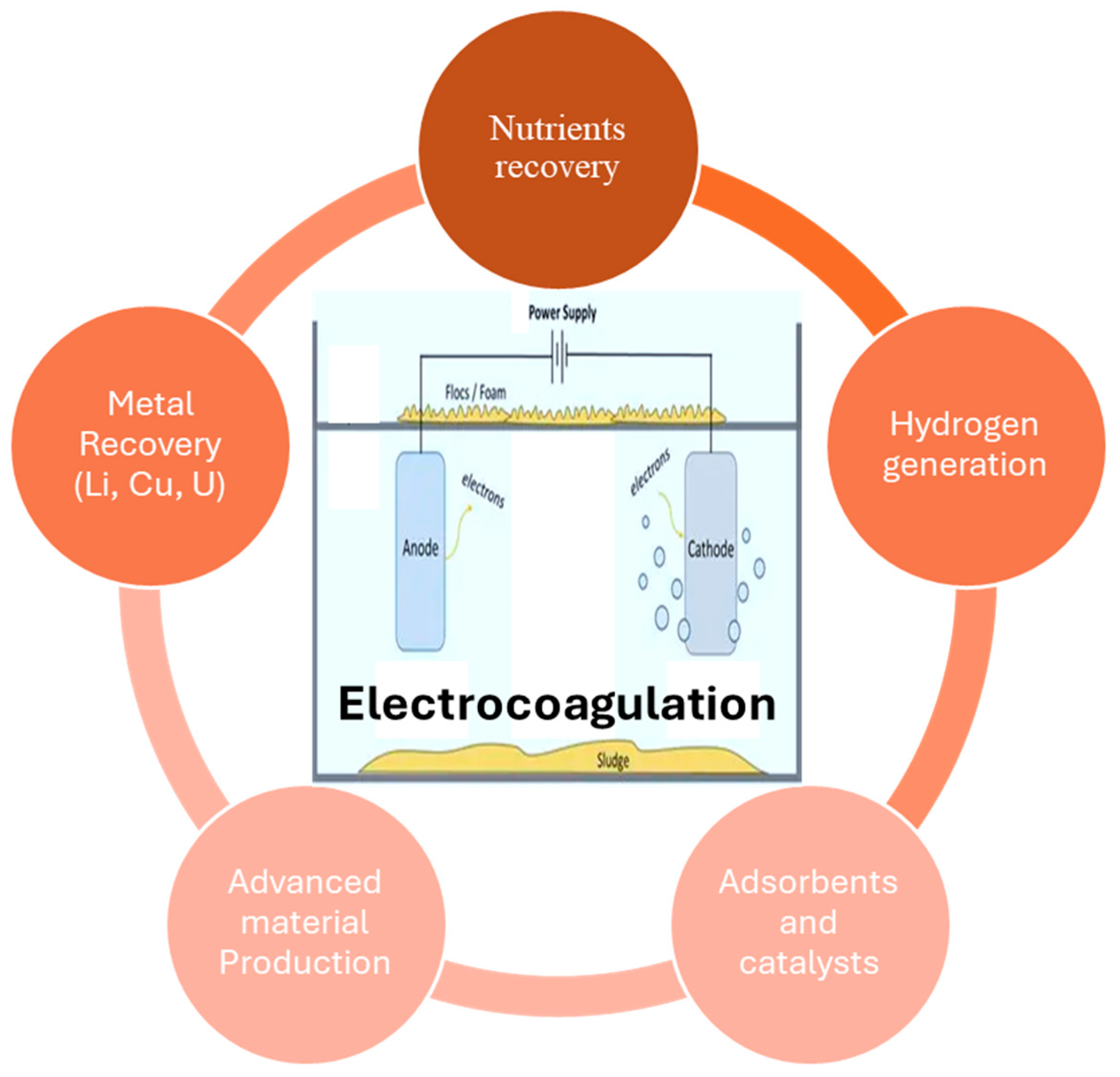
Theoretically, EC is a water treatment process that relies on the in situ generation of coagulant species by applying an electric current to sacrificial metal electrodes—typically made of aluminum or iron—immersed in the contaminated solution. When a voltage is applied across these electrodes, a direct current flows through the solution, initiating electrochemical reactions at both the anode and cathode. At the anode, metal ions (Mn+) are released into the solution through anodic dissolution Equation (1), while hydroxide ions (OH) are produced at the cathode Equation (2). These ions interact to form metal hydroxide flocs M(OH)n(s) as described in Equation (3). These flocs act as adsorbents, destabilizing and aggregating contaminants, which can then be removed by sedimentation [20,24]. Additionally, hydrogen gas generated at the cathode aids in the flotation and removal of certain pollutants from the solution (Figure 1).
Anodic reaction:
M s M a q n + + n e  
Cathodic reaction:
2 H 2 O + 2 e 2 O H + H 2
In solution:
M n + + n O H M ( O H ) n    
Compared to conventional chemical coagulation, EC offers several notable advantages, including reduced chemical consumption, lower sludge production, simplified operation, and improved contaminant removal efficiency. EC systems can be easily combined with physical, chemical, and biological treatment technologies [28,29,30,31,32], and are well suited for operation using solar energy due to their low voltage requirements, making the integrated treatment systems a cost-effective and sustainable alternative [33,34,35,36]. Additionally, the use of scrap metals (e.g., aluminum cans, foil, scrap iron, mild steel) as electrodes has been proposed as a sustainable alternative, since they can achieve high pollutant removal efficiencies (up to ~97% color and ~88% COD reduction) while reducing material costs and promoting circular resource utilization. However, issues such as electrode degradation and potential metal leaching must be considered [37,38].
The performance of the EC process is estimated based on the reduction levels in pollutant concentrations achieved by the EC reactor by calculating the percentage removal or: Removal (%) as [24]:
R e m o v a l % = C 0 C t C 0   × 100    
where C0 is the initial concentration of the pollutants before treatment, and Ct is the concentration of the corresponding pollutants after a certain EC time treatment (t). In addition, the performances of the EC technique can be estimated in terms of energy consumption (E) according to the following equation [24]:
E = U I t 1000 V          
where E is the energy consumption (kWh/m3), U is the voltage (Volt), I is the applied current in ampere (A), t is the EC time (h), and V is the volume of treated solution (m3).
On the other hand, the amount of dissolved anode used in the EC treatment depends on the quantity of electricity passed through the electrolytic solution which can be approximated from Faraday’s law [24].
m = t I M w Z F            
where m is the amount of dissolved anode (g), I is the applied current (A), Mw is the molecular weight of electrode material (g/mole), Z is the valence of the electrode material, and F is Faradays constant (96,485 C/mol).
Over the past few decades, numerous studies have investigated the use of EC for treating different wastewater types, with particular emphasis on pollutant removal efficiency and energy consumption. Although batch EC systems have been thoroughly investigated with great success in terms of pollutants removal and energy consumption, they face limitations in scalability and practicality for continuous, large-scale industrial use. As a result, there is increasing interest in continuous electrocoagulation processes (CEPs), which present a more efficient and scalable alternative. CEPs apply the fundamental principles of EC within a continuous-flow system, enabling real-time treatment of industrial effluents with enhanced energy efficiency, greater automation potential, and improved process control. Moreover, the continuous operation mode facilitates smoother integration into existing industrial wastewater treatment systems, making it a more attractive option for practical implementation [39,40,41,42].
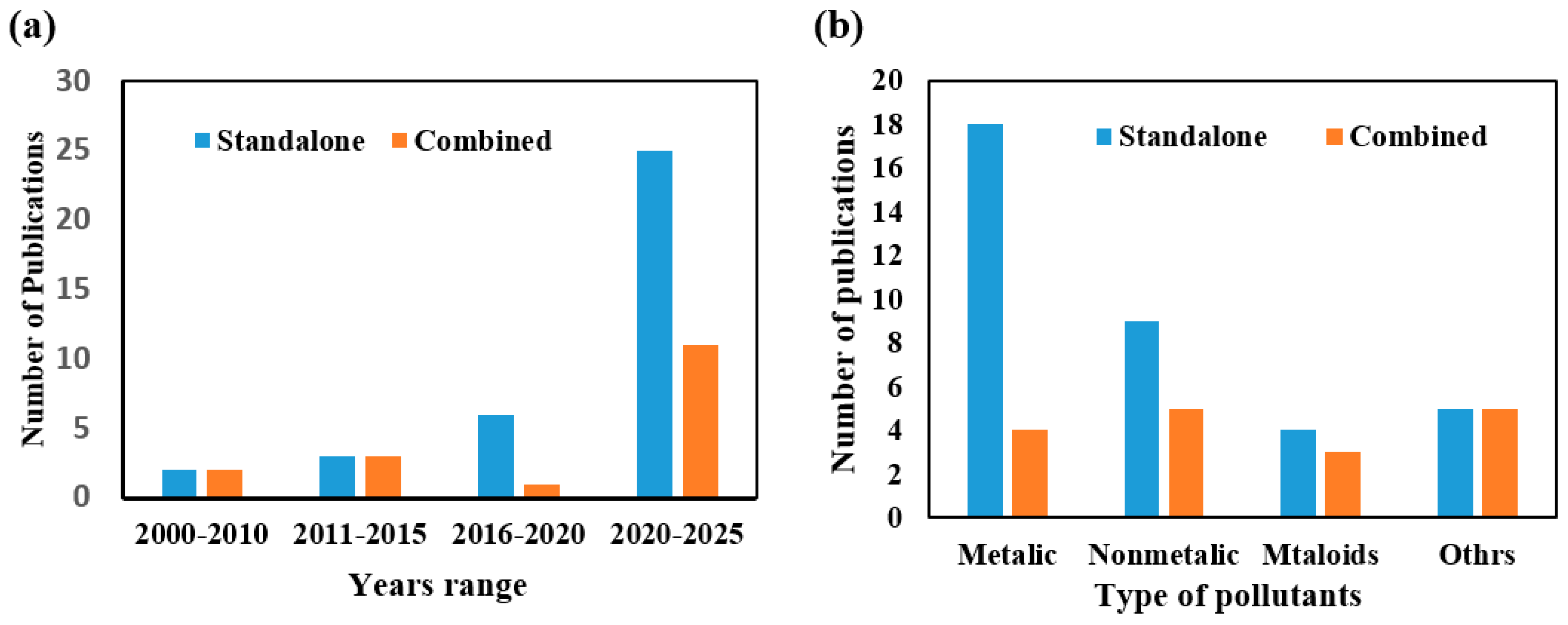
Based on an extensive literature review, approximately 53 papers have been published over the past 25 years on the use of CEPs for the removal of inorganic pollutants. These studies can be categorized into two groups: standalone CEPs [41,42,43,44,45,46,47,48,49,50,51,52,53,54,55,56,57,58,59,60,61,62,63,64,65,66,67,68,69,70,71,72,73,74,75,76] and combined CEPs [77,78,79,80,81,82,83,84,85,86,87,88,89,90,91,92,93]. Figure 2 presents a detailed classification of these 53 studies according to their year of publication and the types of pollutants treated in each group.
Figure 2a shows that the number of publications in continuous standalone and combined EC processes for inorganic pollutants treatment has increased significantly in the last 10 years. In the periods 2000–2010, 2011–2015, 2016–2019, and 2020–2025, there are 2, 3, 6, and 25 publications for standalone [44,48,49,50,51,52,53,54,55,56,57,58,59,60,61,62,63,64,65,66,67,68,69,70,71,72,73,74,75,76], and 2, 3, 1, and 11 publications for combined EC [77,78,79,80,81,82,83,84,85,86,87,88,89,90,91,92,93], respectively. On the other hand, Figure 2b presents the number of publications over the past 25 years related to four major categories of inorganic pollutants in wastewater: metallic, nonmetallic, metalloids, and others. Specifically, 18, 9, 4, and 5 publications have addressed these categories using standalone CEPs, while combined CEPs have been the focus of 4, 5, 3, and 5 publications, respectively. These data indicate that standalone EC systems have been more extensively studied than combined systems. Moreover, the treatment of inorganic metallic pollutants has received the highest level of research attention during this period.
In particular, CEPs have been effectively employed to remove contaminants such as iron [43], fluoride [44,55,56,59], arsenic [45,49,53,57], chromium [46,48,74], and heavy metals from leachate wastewater [74], showing high removal efficiency, low energy consumption, and robust operational stability. Additionally, CEPs have proven to be a sustainable solution for the recovery of valuable inorganic resources, such as nitrogen and phosphorus, which serve as essential plant nutrients and play a vital role in supporting a circular economy [40]. However, the effectiveness of CEPs is affected by several factors, including electrode material and configuration, current density, flow rate, pH, and the composition of the water matrix [94,95,96,97]. More recently, Al-Qodah et al. [98] published a comprehensive review of studies dealing with the performance of continuous electrocoagulation processes (CEPs) used for the treatment of industrial organic pollutants. Therefore, this review represents an additional thorough understanding of CEP mechanisms, operational parameters, and performance metrics, which are essential for its optimization and broader application for the treatment of industrial inorganic pollutants. To the best of the authors’ knowledge, the literature lacks a comprehensive and critical review addressing the latest innovations in using CEPs for removing inorganic pollutants from water and wastewater. This review seeks to fill that gap by systematically evaluating CEPs’ performance in treating inorganic contaminants, highlighting recent advancements, assessing the effectiveness of different system configurations, exploring underlying mechanisms, and identifying knowledge gaps and future research directions to support the development of CEPs as a sustainable and efficient industrial wastewater treatment technology.

2. Methodology

This review paper adopts a systematic methodology to evaluate the performance of CEPs in treating industrial inorganic pollutants. A comprehensive literature search was conducted using scientific databases such as Scopus, Web of Science, and Google Scholar, focusing on studies published between 2000 and 2025. Keywords including “continuous-flow electrocoagulation”, “industrial wastewater”, “inorganic pollutants”, combined electrocoagulation treatment processes”, and “electrocoagulation molding and optimization” were used to filter relevant peer-reviewed articles. Selected studies were critically analyzed based on treatment efficiency, operational parameters, electrode materials and design, pollutant removal mechanisms, and scalability. Comparative assessment techniques were employed to identify trends, challenges, and gaps in current research, thereby providing a consolidated understanding of CEPs’ applicability and future prospects in industrial wastewater management. Conference papers, letters to the editor, books, and short surveys were excluded.

3. Standalone and Combined CEPs for Removing Inorganic Pollutants

3.1. Standalone EC Treatment Processes

The electrocoagulation treatment process is performed by applying electric current to sacrificial electrodes, typically made of iron or aluminum, immersed in the contaminated water to be treated. As the wastewater flows continuously through the EC reactor, the applied current releases metal ions (Fe2+/Fe3+ or Al3+) from the sacrificial electrodes [25]. These ions function as coagulants, neutralize the charges of pollutant particles, leading to reduced repulsive forces, and particles aggregate into larger flocs that can be removed efficiently by sedimentation or flotation. Furthermore, hydrogen gas bubbles generated at the cathode lift the flocs to the surface for separation [44].
EC is very attractive since it can be applied for a wide range of organic and inorganic contaminants with little or no addition of external chemical coagulants, thus reducing chemical handling and secondary contamination. Furthermore, it produces less sludge compared to conventional chemical coagulation. However, the EC performance is affected by the characteristics of the wastewater to be treated. In addition, continuous consumption of sacrificial electrodes increases operational cost and requires periodic replacement. Also, energy demand can be relatively high, especially for large-scale operations. Furthermore, the resulting sludge requires additional treatment and disposal [48,70].
Recent studies have demonstrated the high efficacy of standalone continuous processes (CEPs) for removing various inorganic pollutants. The process typically involves optimized electrode configurations, flow dynamics, and current densities to achieve maximum removal efficiency. Al Anbari et al. [76] reported the first standalone continuous EC treatment process for heavy metal ions from synthetic wastewater. They studied the effect of several parameters such as pH, current density, and initial heavy metal ions concentration. They applied a continuous-flow EC system, with a system containing a ladder series of 12 electrolytic cells; each cell contains a stainless steel (SS) cathode and an iron anode. The removal efficiencies of the heavy metal ions Zn2+, Cu2+, Ni2+, Cr3+, Cd2+, and Co2+ approached 99%. Subsequently, Emamjomeh and M. Sivakumar [44] investigated continuous-flow experiments with monopolar Al electrodes for fluoride removal under various operational parameters, including current density (12.5–50 A/m2), flow rate (150–400 mL/min), initial pH (4–8), and initial fluoride concentration (5–25 mg/L). They reported that the highest fluoride removal efficiency (up to 99%) was achieved at the largest current density (50 A/m2) with a flow rate of 150 mL/min and an initial fluoride concentration of 10 mg/L. The removal efficiency increased with current density, decreased with higher flow rates, and depended on the initial fluoride concentration. The residual fluoride concentration was reduced from 10 to 1 mg/L when the total aluminum concentration ranged between 120 and 155 mg/L, with an Al3+/F mass ratio between 13 and 17.5, indicating the maximum formation of aluminum fluoride hydroxide complexes. XRD analysis confirmed the strong presence of Al(OH)3 in the final pH range of 6–8, which facilitates the formation of these complexes. These results suggest that electrocoagulation is an efficient process for defluorination of potable and industrial water.
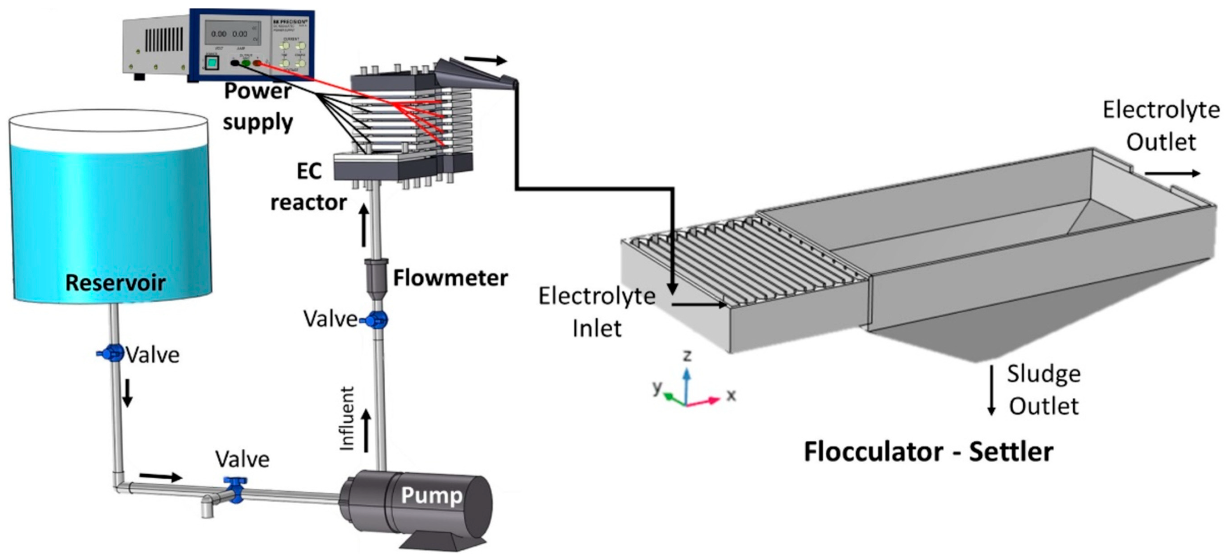
Recently, Tello et al. [62] constructed a new EC system and evaluated its technical performance in the treatment of synthetic wastewater containing a high turbidity level. Their EC treatment system consists of six cells arranged in series and coupled to a flocculator and a sludge decanter. The cells contain a cylindrical Al anode and an SS rod as a cathode. They examined the influence of the type of electrodes used and the applied electric potential on the turbidity and TDS removal in addition to the electrical energy consumption. The values of the electrical potential were 0, 3, 6, and 9 V, and Al or Fe were the anodes. They reported that the turbidity removal efficiency achieved 82.29% and the energy consumption in the case of Al electrodes was 0.7142 kWh/m3. They concluded that the EC process with Al or SS electrodes is an appropriate application for efficient turbidity removal and low electrical energy consumption.
More recently, Hayden and Abbassi [42] and Genawi et al. [46] applied a continuous-flow EC system for the removal of dissolved phosphorus and chromium from wastewater. Hayden and Abbassi [42] optimized the operating conditions of the EC treatment system and achieved a relatively high percentage removal of orthophosphate (OP) and triphosphate of 99.9 and 88.1%, respectively. On the other hand, Genawi et al. [46] applied a continuous EC column to remove chromium ions from tannery industrial wastewater. They applied the continuous EC system to investigate the process dynamics and the system’s steady-state stability. They reported that at optimum conditions, the continuous EC system achieved a high percentage removal of chromium ions close to that obtained in the batch process.
It should be noted that more than 70% of the studies concerning standalone continuous EC treatment processes for inorganic pollutants have been published in the last 3 years. In addition, 50% of them deal with the treatment of metallic pollutants. These results indicate that this technology is now applied at a significantly increasing rate due to its high efficiency and relatively low cost. Accordingly, it is expected that more studies will appear soon, and some of these studies are hoped to be on an industrial scale.
Table 1 summarizes the main parameters and results of research utilizing standalone EC treatment processes for inorganic pollutants removal from different kinds of water and wastewater during the last 25 years.
Table 1 shows that there are 36 studies utilizing standalone EC treatment processes during the last 25 years. The performance of the continuous EC process as a treatment process and its removal efficiency have been improved by optimizing the main operational parameters such as the flow rate, type of electrodes, and their number and arrangement, current density, in addition to the type of wastewater. A clear trend emerges from the table: the continuous EC process demonstrates consistently high removal efficiencies for heavy metal ions, with most studies reporting values exceeding 90%. This high efficacy can be attributed to the strong affinity of metal ions for the in situ generated metallic hydroxides, facilitating rapid coagulation and sedimentation. Examples include the removal of Cr(VI), Ni, Zn, and other heavy metals from various wastewaters, where efficiencies often approach or reach 99–100%.
In contrast, the removal efficiencies for non-metal pollutants, such as nitrates, fluoride, sulfates, and turbidity, tend to be lower, generally ranging from 60% to 85%. This discrepancy likely arises from the weaker interaction of these species with the electrochemically generated coagulants, making their removal more challenging under standalone EC conditions. Several studies indicate that incorporating secondary treatment steps or hybrid systems can significantly enhance non-metal removal. For instance, pretreatment steps or combined EC-adsorption approaches can reduce residual concentrations while mitigating electrode fouling and passivation.
The table also emphasizes the impact of reactor design and electrode arrangement on performance. Variations in electrode geometry, surface area, number of electrodes, and flow patterns influence mass transfer and coagulation efficiency, as seen in reactors employing multi-cell stacks, helical electrodes, or serpentine flow arrangements. Similarly, operational parameters such as current density and pH were often optimized to balance removal efficiency, energy consumption, and electrode wear, highlighting the importance of process parameter tuning.
Energy and operational costs, reported in some studies, show a wide range depending on the pollutant type and treatment conditions, from as low as 0.012 €/m3 for arsenic removal to several US$/kg for nitrate or heavy metal removal in high-volume industrial applications. This underscores the trade-off between removal efficiency and economic feasibility, a key consideration for large-scale implementation.
In summary, Table 1 illustrates that continuous EC is a highly effective treatment for heavy metals, while its performance for non-metal pollutants is comparatively limited. Optimizing operational parameters, adopting hybrid or combined treatment systems, and implementing pretreatment strategies can substantially improve the overall process efficiency and cost-effectiveness. These insights underscore the versatility of EC technology, while also highlighting areas where further research and engineering innovation are needed, particularly for the treatment of recalcitrant non-metal pollutants.
On the other hand, electrode passivation has emerged as the most frequently reported operational challenge in numerous studies on continuous electrocoagulation processes (CEPs). This phenomenon involves the gradual accumulation of insulating layers—typically composed of metallic hydroxides, precipitated salts, or sludge particles—on the surface of the electrodes. Such deposits reduce the effective electroactive area, increase electrical resistance, and diminish the rate of coagulant generation, ultimately compromising the overall efficiency of pollutant removal. Passivation poses a significant challenge because it directly impacts energy consumption, process stability, and the long-term scalability of the treatment system. Various mitigation strategies have been proposed, including periodic polarity reversal, mechanical or chemical cleaning of the electrodes, hydrodynamic optimization to reduce sludge buildup, and pretreatment to lower suspended solid concentrations. The selection of electrode material is also critical, as aluminum and iron differ in their susceptibility to fouling depending on the wastewater composition. Effectively addressing electrode passivation is essential for maintaining optimal reactor performance and ensuring the sustainable industrial application of CEPs.

3.2. Combined Continuous Electrocoagulation Processes (CEPs)

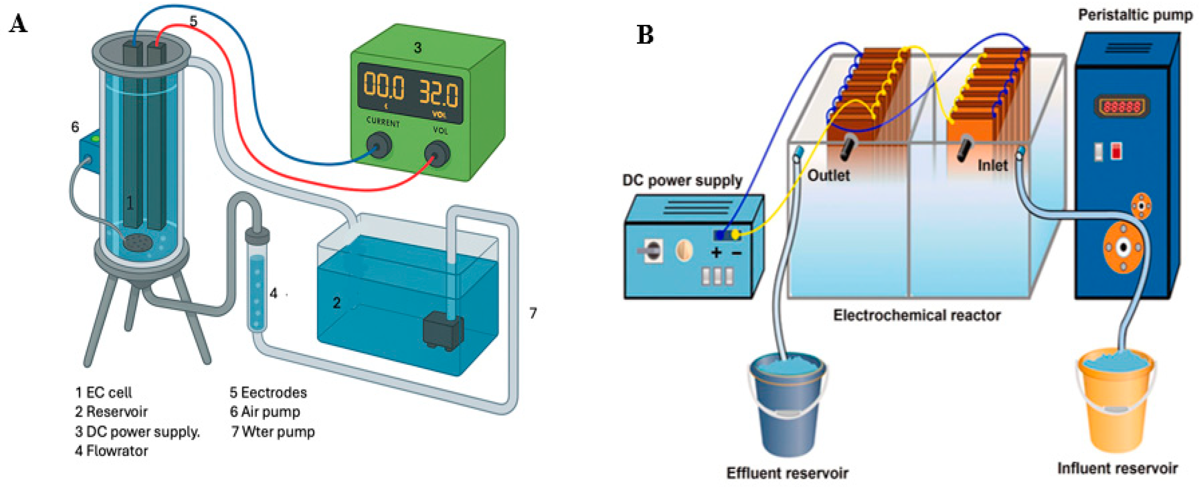
In integrated continuous electrocoagulation processes (CEPs), the EC unit is integrated with other treatment technologies, such as flotation, sedimentation, membrane filtration, and advanced oxidation, to improve overall treatment performance as presented in Figure 3.
As shown in Figure 3, the residual water flows through the EC reactor, where sacrificial electrodes liberate ions from the coagulation and generate aggregation. The partially treated effluent serves as a complementary process for contaminant separation or further reduction. For example, EC can be followed by flotation with improved aeration for greater particle removal, or combined with membrane filtration for a higher-quality effluent with less fouling. Synergistic effects significantly improve the overall contaminant removal efficiency compared to standalone EC. Furthermore, they reduce chemical demand and sludge generation. CEPs also improve effluent quality to meet standards for possible water reuse, making the process more suitable for emerging industrial applications. However, it requires significant capital and operating costs due to the integration of multiple processes, with the design and operation of more complete systems requiring optimization and qualified operators. Energy consumption and operational requirements increase, particularly when using membranes or flotation units.
An extensive review of the literature reveals that over the past 25 years, only 17 studies have been published on combined continuous electrocoagulation processes (CEPs) for the treatment of inorganic pollutants. Table 2 summarizes the key operational and designed parameters and research findings from these 17 studies from various types of water and wastewater. It should be noted that combined electrocoagulation (EC) treatment processes for inorganic pollutants serve as alternatives to standalone EC systems, offering enhanced removal efficiency for high inorganic loads in industrial wastewater. These integrated treatment systems can incorporate the EC process in one of the following three configurations:
A first treatment step followed by another treatment process such as adsorption, microfiltration, or nanofiltration [77].
A second treatment step after another treatment step such as chemical coagulation or advanced oxidation processes [93].
An intermediate treatment process between two treatment processes [30].
The significant findings presented in Table 2 confirm that, in most of the combined continuous electrocoagulation processes (CEPs), the EC step is used as the initial treatment stage. The first paper was published by Mavrov et al. [77], who reported the use of a hybrid EC membrane system to remove selenium from industrial wastewater. Their results were promising, and the percentage removal of Se, As, Cu, Pb, Zn, and Cd were 98.7, 99.9, 98.0, 98.0, 99.9, and 99.9%, respectively.
Subsequently, several researchers, including Bani-Melhem et al. [79], Jebur et al. [82], Channa et al. [87], Basha et al. [92], Bennajah et al. [96,99,100,101,102,103] and Uludag-Demirer et al. [104], have implemented EC-based combined treatment systems and reported promising results and recommendations, as summarized in Table 2.
Analysis of the studies summarized in Table 2 reveals several key patterns and insights. EC was applied as a pretreatment step in 15 studies and as a post-treatment step in only 2 studies, indicating that EC is most effective when used initially to reduce inorganic pollutant concentrations before subsequent treatment stages. The main processes combined with EC include microfiltration, ultrafiltration, and nanofiltration [77,78,79,82,83,84,87,88,89,91], as well as filter press systems [80,81], flotation [85], ultraviolet treatment [90], and fluidization–sedimentation techniques [89]. In contrast, processes applied prior to EC include ion exchange [92] and chemical coagulation [93].
Pollutant removal efficiencies were notably high, reaching 100% for arsenic [87], over 99.9% for zinc and cadmium [77], and 99% for color removal [88], confirming the effectiveness of EC-based combined treatment systems. However, energy consumption and operational costs varied widely, suggesting a need for optimization of electrode configuration, current density, and flow rates. Furthermore, no studies evaluated EC as an intermediate step, highlighting a potential area for future research. Overall, these findings support the critical role of EC as a pretreatment step in combined processes and emphasize the need for further research to optimize parameters and scale-up for industrial applications.

4. Mathematical Modeling of CEPs for Inorganic Pollutant Removal

Mathematical modeling is an essential tool for understanding, designing, and optimizing continuous EC systems for removing inorganic pollutants from water and wastewater. By enabling predictive analysis of process performance under varying operating and design conditions, modeling supports the development of efficient, cost-effective, and environmentally compliant treatment systems. However, modeling continuous EC remains a challenging task due to the complexity of the coupled electrochemical, chemical, and physical phenomena involved. These include electrode dissolution and speciation, hydrolysis and polymerization of metal hydroxides, multi-mechanism pollutant removal, mass transfer limitations, hydrodynamic non-idealities, and electrode passivation. The performance of EC systems is further influenced by operational parameters such as current density, electrode material and configuration, influent composition, pH, flow rate, and reactor geometry [59]. Given these complexities, different types of mathematical models have been developed in the literature, each with specific objectives and methodological approaches. This review section classifies and discusses these models in three main categories:
Kinetic models describe the rates of electrochemical dissolution, coagulant generation, and pollutant removal reactions [94]. These include empirical rate laws such as the first-order kinetic model, and second-order kinetic model [71], pseudo-first-order, pseudo-second-order [95], variable-order kinetics (VOK) [55], and transport–reaction models. Kinetic modeling is essential for understanding mechanistic pathways, quantifying reaction rates, and supporting reactor design and scale-up by providing parameters such as rate coefficients and reaction orders [94].
Isotherm models characterize the equilibrium relationships between pollutant concentrations in solution and on the surfaces of electro-generated coagulants [94]. Commonly used isotherms, such as Langmuir, Freundlich, and Langmuir–Freundlich models [96], describe adsorption capacities and surface heterogeneity. Isotherm analysis is critical for estimating maximum pollutant loading, informing reactor sizing, and interpreting adsorption mechanisms in EC systems.
Optimization and empirical models aim to identify optimal operating conditions to achieve target removal efficiencies while minimizing energy consumption and costs. These models often use regression analysis, response surface methodology (RSM), or machine learning approaches to relate operational to performance metrics, enabling practical process control and scale-up [59].
This section reviews these diverse modeling approaches for continuous EC processes treating inorganic pollutants. It summarizes key methodologies, assumptions, and findings from recent literature for both standalone and combined systems. By clarifying the strengths and limitations of kinetic, isotherm, and optimization models and highlighting the role of transport and hydrodynamic modeling, this review aims to support the development of robust, scalable, and cost-effective EC treatment strategies.

4.1. Kinetic and Isotherm Modeling of Continuous Electrocoagulation Processes

4.1.1. Standalone Processes

Kinetic and isotherm modeling are essential to understand and optimize standalone EC processes for inorganic pollutant removal. These models capture the rate and extent of contaminant removal via mechanisms such as adsorption, precipitation, and coagulant formation. Early models relied heavily on empirical kinetics and adsorption isotherms; however, recent studies have expanded the modeling landscape to include transport, hydrodynamics, and electrochemical charge interactions, which are vital for scaling continuous systems.
Kinetic modeling quantifies how fast pollutants are removed under specific operating conditions. The pseudo-second-order model, commonly used across recent studies, assumes chemisorption as the rate-limiting step and is expressed in Equation (7) [97,98]:
t q t =   1 k 2 q e 2 + t q e
where k2 is the pseudo-second-order rate constant (g mg−1 min−1), and qe and qt refer to the quantity of pollutant adsorbed at time of equilibrium and time t. This model has been widely applied due to its consistency with observed behavior in EC systems treating metals like Ni, Cr, and Fe [71].
Some systems exhibit more complex kinetics. For example, VOK was successfully applied to model fluoride removal from volcanic spring water using bipolar Al electrodes [55]. The model’s power-law form allowed adaptation to concentration-dependent changes in reaction order as described in Equation (8):
d F d t = ε A l . ε C n . I Z . F . V . T m a x k . F 1 + k . F
where εAl is the yield of hydro-fluoro-aluminum formation (%), εC the current efficiency, n the cell number, I the current (A), Z the valence, F the Faraday constant, V the working volume (L) of water in the reactor, and Γmax the maximum amount of fluorides removed per mole of Al(III) at a given pH, and k the Langmuir constant (L/mol).
The model applied by Betancor-Abreu et al. (2019) [55] using VOK model derived from Langmuir equation achieved excellent agreement with experimental data (R2 > 0.99), confirming its suitability for reactor design and scale-up. This work highlights the utility of VOK modeling in capturing complex EC kinetics where reaction order varies with concentration, supporting the design of optimized continuous-flow systems for drinking water treatment [55].
Isotherm models are critical for describing equilibrium pollutant adsorption onto in situ–formed metal hydroxides. The Langmuir isotherm, often used in EC literature, assumes monolayer adsorption on a homogeneous surface and is defined as Equation (9) [99]:
C e q e =   1 Q 0 b + C e Q 0
where Q0 is the Langmuir constant related to the monolayer capacity (mg/g), b is the binding energy constant; Ce: equilibrium concentration mg/L; qe: amount of material removed at equilibrium condition (mg/g).
Applications of the Langmuir isotherm include boron removal from produced water, where both the Langmuir and Freundlich models provided good fits, confirming surface heterogeneity and multilayer adsorption behavior [99].
Beyond classical kinetics and isotherms, hydrodynamic and transport–reaction models have advanced understanding of flow-related impacts on EC performance. Residence Time Distribution (RTD) and Conversion Time Kinetics (CTV) models have been combined to account for short circuiting and internal recirculation in semi-continuous EC reactors [63]. These methods quantify flow deviations from ideal plug-flow, enabling accurate estimation of required treatment time and coagulant dose. A particularly detailed approach was demonstrated in the removal of Cr(VI) from ammonium nitrate-rich wastewater by Vargas et al. [63], where an advection–dispersion–reaction model was used to track Cr concentration profiles along a plug-flow reactor. The model accurately estimated kinetic rate coefficients under different flow rates, highlighting the importance of integrating flow and electrochemical parameters in reactor design.
Advanced kinetic modeling in continuous EC includes CFD and transport–reaction frameworks. Valentín-Reyes and Nava [100] used a two-phase CFD model with Reynolds-Averaged Navier–Stokes (RANS) equations and slip flow to predict hydrogen bubble behavior and ferric coagulant generation in a cascade reactor, validating Fe3+ dosing with <4% deviation. Costigan et al. [74] applied an advection–dispersion–reaction model in a plug-flow reactor to simulate Cr(VI) reduction and precipitation, estimating rate coefficients under varying flow and current. Both studies underscore the value of mechanistic models for linking electrochemical generation, mass transport, and reactor design.
In summary, modeling efforts for standalone continuous EC systems span from empirical kinetics and isotherms to advanced CFD and RTD-based frameworks. While pseudo-second-order and Langmuir-type models remain prevalent, studies increasingly show that transport phenomena and reaction-flow coupling must be considered for accurate prediction and design. As shown in Table 3, these models provide critical insights into coagulant dosing, energy consumption, and pollutant removal dynamics, laying the foundation for cost-effective, scalable EC systems.

4.1.2. Combined Processes

Recent research has demonstrated that combining EC with other treatment steps or reactor designs can significantly enhance contaminant removal efficiency, particularly for challenging wastewater matrices. Modeling approaches remain essential in these combined processes for understanding kinetics and informing scale-up.
Bennajah et al. [96] investigated fluoride removal from synthetic drinking water using EC/electroflotation in both stirred-tank and airlift reactors. Their kinetic study applied a VOK model based on the Langmuir–Freundlich isotherm, which showed excellent agreement with experimental data (R2 = 0.998). The model’s fit suggests adsorption occurs on heterogeneous surfaces with sites of variable energy. The coefficient n was found to be greater than 1 (N = 1.15 ± 0.03), indicating positive cooperativity in fluoride adsorption. This supports a mechanism in which fluoride removal involves both external surface adsorption and intercalation into interlayer spaces within the floc structure. Additionally, the Langmuir–Freundlich model yielded qmax values close to 1 mmol/g, consistent across both kinetic fitting and equilibrium isotherm data. This consistency reinforces the reliability of the modeling approach for predicting process performance. Overall, the study demonstrates that combining EC with advanced isotherm and kinetic modeling provides a robust framework for optimizing defluorination processes in drinking water treatments [96].
Despite this promising example, only one modeling-focused study of combined processes was identified in the literature, highlighting the need for more research to develop robust design frameworks and predictive models for integrated EC treatment systems. Table 3 shows a summary of kinetic and isotherm modeling studies of CEPs.
Table 3 summarizes kinetic and isotherm modeling studies for both standalone and combined continuous EC processes. For standalone systems, most studies employ Langmuir and Freundlich isotherms or pseudo-second-order kinetics, showing excellent fits (R2 > 0.98), confirming chemisorption-dominated mechanisms. Advanced models such as VOK, RTD, and CFD address transport and flow effects, supporting scale-up by estimating residence time and coagulant dose more accurately.
For combined processes, the table shows fewer studies overall, but with strong model fits as well (R2 in the range of 0.95–0.998). These examples illustrate that combining EC with flotation or chemical precipitation can improve removal efficiencies, while kinetic modeling remains essential to optimize parameters such as current density, electrode configuration, and coagulant dose. Despite promising results, the limited number of modeling studies for combined systems highlights a research gap in developing predictive tools for integrated treatment designs.

4.2. Operational Parameter Optimization by Statistical and AI Methods

4.2.1. Standalone Continuous Electrocoagulation Processes

Optimization of operational parameters is critical to improving the efficiency, cost-effectiveness, and scalability of continuous-flow EC systems for inorganic pollutant removal. Recent research demonstrates a clear shift toward the systematic use of statistical experimental design and advanced modeling, including machine learning (ML), to identify and fine-tune the key factors that govern EC performance.
Statistical methods such as Taguchi, factorial designs, and RSM have proven especially effective for mapping the complex, often nonlinear relationships between operating variables (e.g., current density, pH, and flow rate) and treatment performance. For instance, structured Taguchi designs have enabled researchers to balance removal efficiency with cost considerations by rigorously identifying the most influential operational parameters [51]. RSM approaches, including Box–Behnken designs, are frequently used to model and optimize multiple variables simultaneously, handling interactions and curvature in the response surface with high accuracy [43,61].
Typically, such optimization studies reveal current density and pH as dominant factors influencing removal efficiency, energy consumption, and sludge generation. For example, the optimization of iron removal from synthetic waters using drilled-plate electrode designs not only achieved near-complete removal (~99.9%) but also demonstrated substantial cost reductions through improved internal mixing, eliminating the need for external agitation [43]. Similarly, oily industrial wastewater treatment has benefited from RSM-based optimization of electrolysis time, current density, and flow rate, achieving significant reductions in total dissolved solids while maintaining strong model predictivity [61].
Beyond traditional single-cell reactors, innovative multi-cell and electrode configurations have been evaluated using factorial designs to understand the interactions among voltage, electrode type, and energy use. For instance, continuous systems with series-connected aluminum and stainless steel electrodes achieved over 80% turbidity removal at optimized voltages while maintaining low energy demands (0.7142 kWh/m3) [62]. These studies highlight the power of factorial designs for not just maximizing removal efficiency but also quantifying energy requirements, an essential consideration for practical deployment.
Optimization studies have also targeted the treatment of specific contaminants of emerging concern. Iron-based EC systems have been systematically optimized for the removal of toxic molybdate (Mo(VI)) using Box–Behnken RSM approaches. Such work emphasizes the importance of tuning pH, current density, and electrode spacing to achieve over 80% removal efficiency in continuous-flow, while robust modeling enables prediction of performance across varying conditions. Figure 4 illustrates typical interaction effects among operational parameters, underscoring the value of statistical designs in elucidating the system’s response landscape [68].
Machine learning approaches are emerging as powerful complements to traditional statistical designs. For instance, Gradient Boosting Machine (GBM) models have been employed to optimize arsenic removal in continuous-flow systems, identifying treatment duration as the single most influential variable while also capturing the nuanced effects of coagulant dose, pH, and current density [45]. The general form of a GBM regression model can be written as Equation (10):
y ^ = F M x = γ 0 + m = 1 M ν γ m h m x
where y ^ is the predicted value, γ 0 is the initial prediction, ν is the learning rate, γ m is the weight of the m-th tree, and h m ( x ) is the m-th regression tree fitted to the residuals. Such AI-driven optimization provides a high degree of predictive accuracy (R2 > 0.97) and can balance operational costs against regulatory goals, such as achieving WHO limits for arsenic in drinking water.
Optimization is also critical in adapting EC technology to real-world conditions, such as treating drinking water impacted by landfill leachate. Here, factorial experimental designs with alternative electrode materials (e.g., Mg/Zn) have demonstrated high nitrate removal efficiencies (>93%), while also achieving significant co-removal of silica, phosphates, sulfates, and hardness, highlighting EC’s versatility for integrated water quality management [69].
In addition to empirical optimization, mechanistic simulation models have been developed to support reactor design and scale-up. For example, combining ionic transport modeling (MATLAB) with geochemical speciation (PHREEQC) has allowed for the prediction of Cr(VI) removal dynamics in flow-through systems, accounting for complexation, redox reactions, and precipitation equilibria [75]. Such models provide valuable design criteria (e.g., identifying suitable current density ranges) and support better predictive control of continuous EC systems.
Overall, the integration of structured experimental design, advanced statistical modeling, and emerging AI methods represents a transformative shift in the field. These approaches enable not only improved contaminant removal efficiencies but also reductions in energy consumption and operational costs, while novel reactor and electrode configurations further enhance process scalability and adaptability. Collectively, these advances underscore the critical role of rigorous optimization in making continuous-flow EC a viable, cost-effective, and sustainable technology for a wide range of water treatment applications.

4.2.2. Combined Continuous Electrocoagulation Processes

Although several studies have investigated combined EC processes, the application of advanced statistical and modeling approaches for operational parameter optimization remains scarce. For example, Dong et al. (2024) [85] examined silica removal from manure treatment effluent using a tubular electrocoagulation-flotation (EC-F) reactor with aluminum electrodes. Using RSM coupled with central composite design, they optimized pH (8.2), current density (160 A/m2), and electrolysis residence time (23 s), achieving an 88% silica removal. This pretreatment reduced reverse osmosis membrane fouling potential by 28%, and operational costs were as low as 1.75 €/m3. While such studies demonstrate promising contaminant removal and process efficiency, comprehensive modeling and optimization efforts remain limited for combined EC systems. This highlights the need for further research employing rigorous statistical and AI-driven methods to better understand and optimize these integrated treatment technologies across diverse applications [85].
Nevertheless, comprehensive modeling and AI-driven optimization approaches remain scarce for these hybrid configurations. There is a clear need for further research to develop and validate robust models that can capture the complex interactions inherent in combined processes, supporting their wider adoption across diverse water treatment scenarios.
Table 4 provides an overview of experimental design methods employed for optimizing standalone and combined CEPs targeting inorganic pollutants. Among these, RSM designs such as Box–Behnken and Central Composite are most frequently applied due to their efficiency in handling nonlinear interactions. Recently, machine learning approaches like GBM have also emerged, offering enhanced prediction accuracy, although traditional statistical models remain prevalent for their simplicity and interpretability.
Table 4 shows that RSM approaches, especially Box–Behnken and Central Composite Designs, are most frequently applied to optimize standalone continuous EC systems, effectively handling nonlinear interactions among key variables like pH and current density. Machine learning methods such as GBM are emerging for complex contaminant removal with high predictive accuracy, while factorial designs and mechanistic simulations also remain important tools.
For combined EC processes, however, the table highlights limited use of advanced optimization methods, with only a single CCD-based study reported. This indicates a clear need for further research to apply and expand these modeling approaches to hybrid systems, enabling better understanding and control of their more complex interactions.

5. Design Innovations in Electrocoagulation Processes

5.1. Standalone Continuous EC Processes

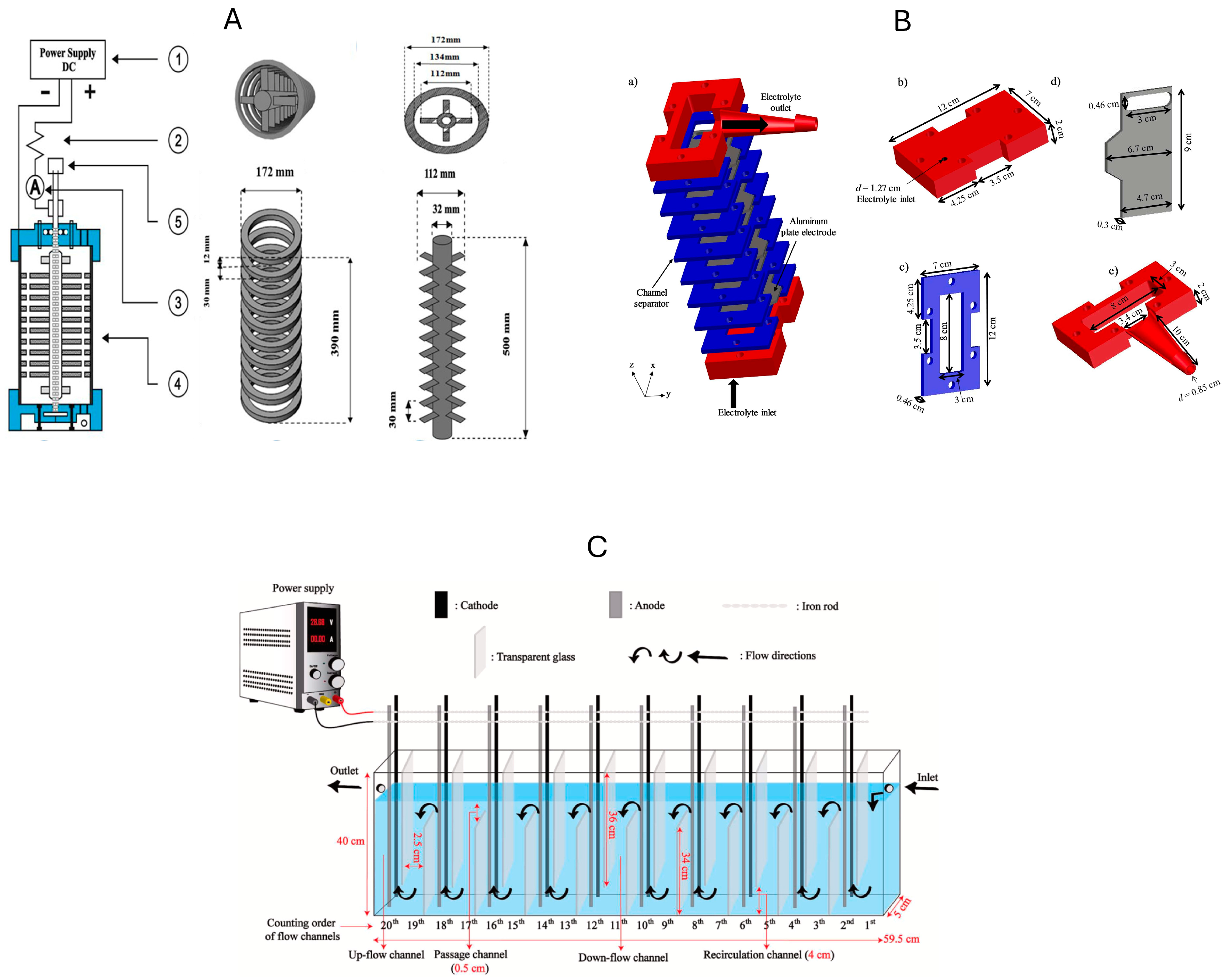
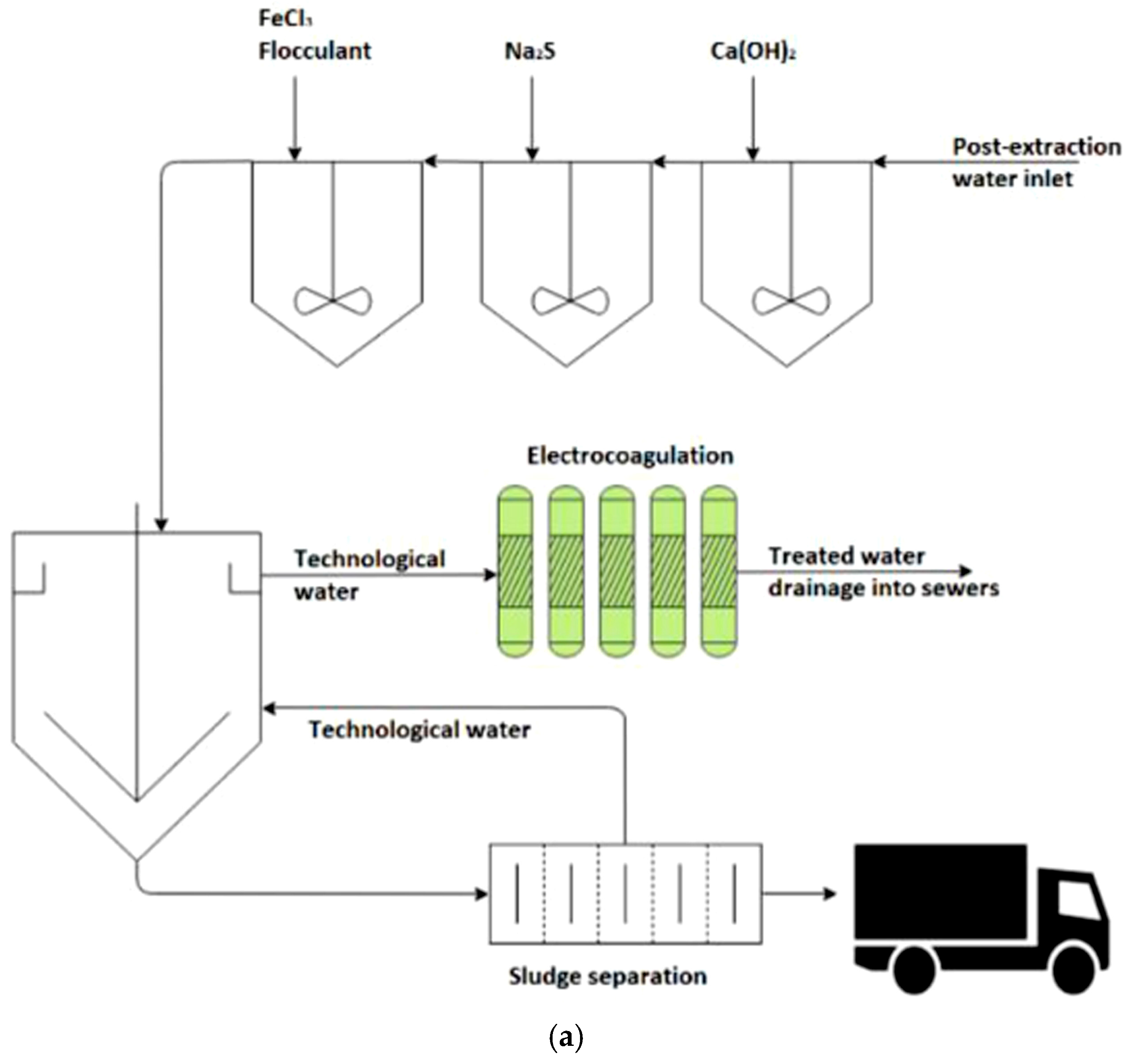
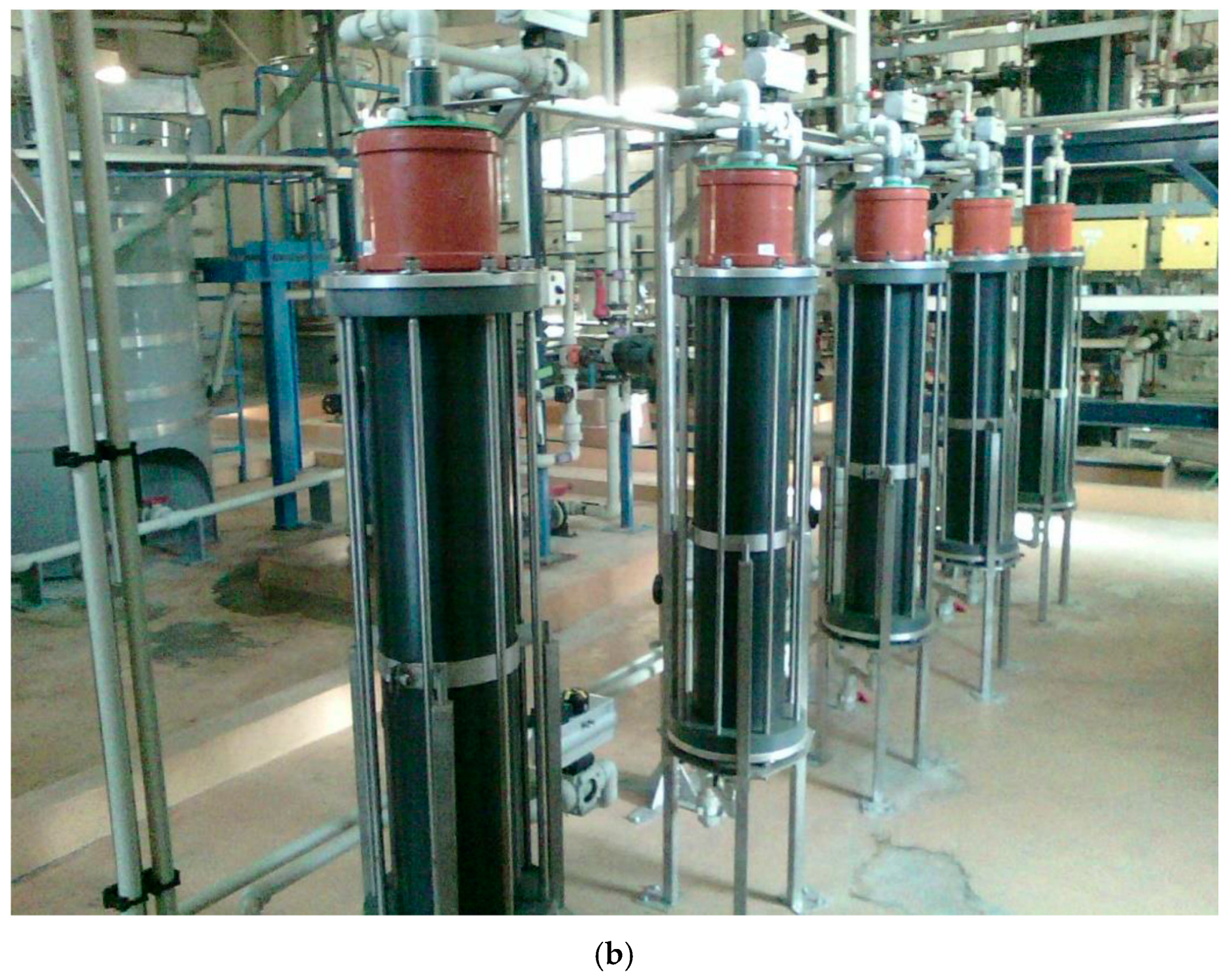
Over the past two decades, continuous-flow EC reactors have experienced important innovations to address the restrictions of batch processes and meet the demands of large-scale industrial wastewater treatment. Several studies have been published in the last decades to apply continuous EC processes as an important step prior to the industrial scale applications as shown in Figure 5.
Xu et al. [52] were the first research group to introduce a continuous EC system shown in Figure 5A. This system operates in batch-recirculation mode for treating real wastewater containing high levels of Zn2+, Cd2+, and Mn2+. Wastewater flows from the bottom through a funnel inlet, with aeration provided via a header placed on a perforated base plate. This design allows for precise control of flow rate, aeration, and current density. Furthermore, it enables easy integration of various anions such as sulfate and sulfite for enhanced coagulation. This reactor achieved an excellent metal removal efficiency of 99.9% for Zn2+. The design’s innovative features, such as modular continuous mode, effective aeration control, and adaptability to real, complex wastewater, demonstrate its high potential for industrial-scale application in toxic metal remediation. Babu et al. [57] used a continuous aerated iron EC reactor with two key innovations: external aeration and polarity reversal, as shown in Figure 5B. It is clear from Figure 4b that the external aeration facilitates the formation of highly reactive oxidants, such as Fe(IV) ions, which promote the oxidation of As(III) to easily removed As(V). In addition, periodically switching the polarity of the iron electrodes after each cycle helps prevent electrode passivation, a common problem in CEPs, and maintaining consistent coagulant generation and removal efficiency over a long period of operation. These innovations enable high arsenic removal efficiency while improving electrode life and process stability.
To minimize energy consumption related to external mixing devices, many designs have emerged as shown in Figure 6.
Abdulhadi et al. [43] presented a new design for a continuous EC reactor that significantly improves performance while reducing energy consumption. Unlike conventional EC systems that rely on external stirrers, the new reactor incorporates an innovative electrode design. The reactor consists of a rectangular container with four rectangular aluminum electrodes, each perforated with 35 holes arranged in staggered lines. The holes in the anodes are offset from those in the adjacent cathodes, creating a complex flow path that forces the water to mix internally as it passes through the reactor. This passive mixing mechanism enhances coagulation efficiency and reduces energy requirements. This design innovation resulted in a remarkable iron removal efficiency of 99.9% while achieving a lower operating cost. Another internal mixing innovation was introduced by Al-Raad and Hanafiah [60]. They integrated a rotating anode with propellant plates within a semi-continuous cylindrical EC reactor. It is made of immobile cathode rings and a rotating shaft anode; all made of aluminum, as shown in Figure 6A. Castañeda et al. [56] designed a flow-channel EC reactor, equipped with a six-cell herringbone array of horizontally arranged aluminum sheet electrodes as shown in Figure 6B. The top of this reactor is open to the atmosphere for rapid release of hydrogen gas. This unique reactor design allows the electrolyte to flow in a tortuous path through multiple electrode cells, improving contact time and mixing. The open-top design prevents gas buildup and electrode failure, ensuring stable operation at high current densities. This design enables the simultaneous and efficient removal of fluoride and hydrated silica with low energy consumption. Similarly, Valentín-Reyes and Nava [100] designed a novel continuous cascade EC reactor with seven iron plates arranged horizontally to create a tortuous flow path, and it is open at the top to release hydrogen bubbles. Salinas-Echeverría et al. [41] developed a continuous-flow EC reactor that features 20 interconnected channels arranged in series, as shown in Figure 6C. This design provides an effective processing volume of 8.7 L and includes 20 aluminum electrode plates in a monopolar parallel configuration to reduce energy consumption. Furthermore, the reactor includes internal glass plates acting as flow reversers for improving hydrodynamic conditions.
On the other hand, Abreu et al. [55] proposed a reactor design that represents a significant innovation in EC technology, moving from small-scale batch systems to a scalable continuous-flow system. Featuring a large working volume of 2 L, this reactor incorporates 14 aluminum electrodes with a surface area of 840 cm2. The electrodes are 5 mm apart and positioned perpendicular to the water flow, enabling crossflow operation. This setup enhances mixing and contaminated electrode contact through a recirculation pump and strategically positioned inlet and outlet, promoting uniform flow and effective floc separation. The two-electrode configuration ensures even corrosion and simplifies maintenance. As a result, this reactor achieved consistent fluoride removal, reducing concentrations from 7.35 mg/L to below 1.4 mg/L. Hamdan and El-Naas [48] proposed an innovative design as shown in Figure 7.
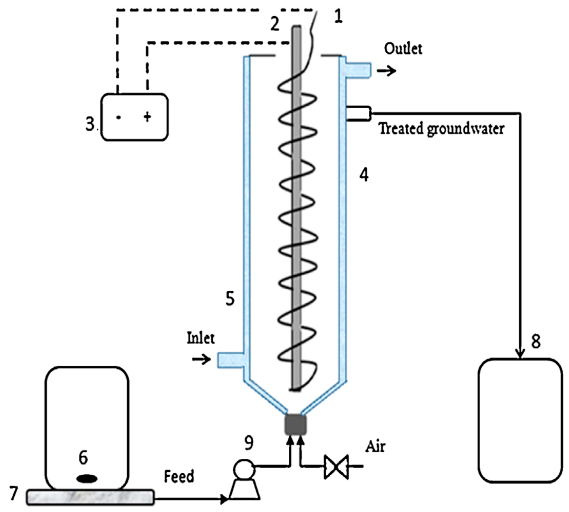
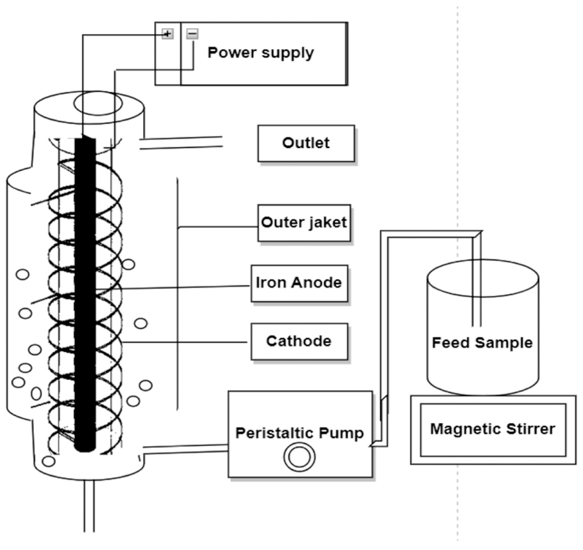
As shown in Figure 7, it combines a symmetrical cylindrical geometry with an air jet injected into the base to create cyclic water movement between the electrodes and the reactor wall, reducing air circulation, enhancing mixing, and producing a uniform liquid velocity distribution. A spiral iron cathode wrapped around a central iron anode increases the electrode surface area and ensures uniform current distribution. Combined with bottom feed injection and a temperature control jacket, these features significantly improve contaminant contact with the coagulants, enhance removal efficiency, and ensure continuous and stable operation [48].
Additionally, Aljaberi et al. [61] implemented a new EC reactor featuring a single-sided aluminum cathode with 27 fins strategically positioned between a pair of cylindrical aluminum anodes. This design increases the cathode surface area within a minimal reactor volume, thus addressing the trade-off between rapid oxidation at the anode and slow reduction at the cathode. This reactor design improved pollutant removal efficiency by maximizing the cathode surface area, promoting hydroxyl (OH) ion production, thus, increasing the production of electrocoagulants, thus increasing pollutant removal efficiency from oily wastewater. Genawi et al. [46] applied a continuous EC reactor with compact concentric cylindrical design combined with enhanced mixing via bottom aeration as shown in Figure 8.
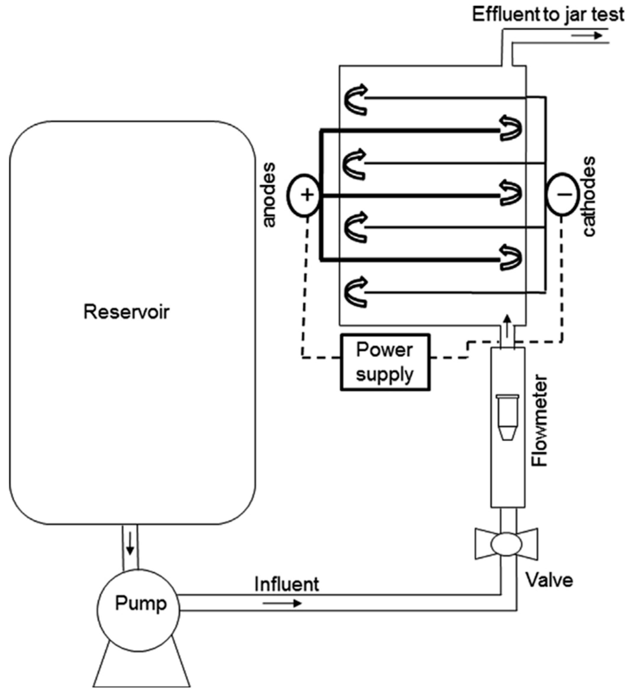
As shown in Figure 8, the iron rod anode is placed centrally while a long iron wire cathode is spirally wrapped around it to maximize the electrode surface area-to-volume ratio and enhance electrochemical efficiency. Instead of mechanical agitation, the reactor uses an air jet injected at the bottom (10 L/h) for effective mixing and improved removal efficiency without extra mixing devices [46]. Costigan et al. [74] employed a compact, vertical EC reactor featuring a central iron rod anode and a surrounding stainless steel mesh cathode arranged concentrically within a column. The iron rod anode is in the center, with a precisely controlled gap between it and the mesh cathode, ensuring even electric field distribution and efficient ionic migration. The use of a mesh cathode increases surface area, allowing for improved solution flow and mass transfer around the electrodes. Hayden and Abbassi [42] designed a modular, multi-column system, as shown in Figure 9, which enhances scalability, flow uniformity, and treatment efficiency.
As shown in Figure 9, the system consists of three vertical PVC treatment columns connected via horizontal PVC tubing using sanitary T-shaped and elbow fittings, producing a total effective treatment volume of 2.78 L. Each column is equipped with two submerged aluminum sheet electrodes connected in a single-pole, parallel configuration, ensuring uniform current distribution and improved EC performance. The system operates with a continuous, upward flow, which promotes even inflow distribution, prolonged contact time, and effective floc suspension [42].
Table 5 shows that some of these innovations include reactor geometry, electrode configuration, flow management, mixing strategies, and operational scalability.
These design advances aim to improve pollutant removal efficiency, decrease energy consumption, improve scalability, and increase economic feasibility. A major trend is the move toward modular and scalable designs, such as multi-column systems [42] and ladder series electrolytic cells with narrow concentric gaps [76]. These configurations improve mass transfer and reduce energy consumption, allowing efficient operation at higher flow rates with plug-flow characteristics and minimal dead zones [41]. Compact vertical reactors with concentric designs [46,74] and herringbone flow paths [56,100] promote uniform electric field distribution, bubble detachment, and enhanced coagulant dispersion, leading to better flow control with higher treatment efficiency.
Electrode innovation has been crucial. Hybrid Fe–Al configurations [45,49,53], and strategically holed or finned electrodes [43,61,73] improve coagulant generation, surface area utilization, and mixing efficiency without external mixers, leading to higher contaminant removal efficiency with lower operating costs. The use of rotating anodes [60] and reversible polarity systems [45] further optimizes electrode usage, minimizes passivation, and prolongs electrode lifespan, contributing to sustainable and cost-effective operation. Innovations in internal aeration systems [46,48] and dual-propeller mechanisms [63] provide uniform mixing and improve mass transfer rates, while configurations that avoid short circuiting [67] ensure that the full reactor volume is effectively utilized. Systems designed for real and complex wastewater [52], and full-scale implementations with parallel operation and spare units [65] show a clear transfer from laboratory scales to industrial applications, with operational flexibility and reliability.
Among the various innovations in continuous CE reactors discussed in this section, the ladder configuration significantly improves mass transfer and reduces energy losses, the Fe–Al–Al–Fe electrode arrangement demonstrates superior contaminant removal with minimal energy input and short reaction times, and the multichannel reactor with flow reversers promotes plug-flow, reduces back-mixing, and ensures high pollutants removal at high flow rates with low operating costs. Together, these three innovations address key limitations in EC technology: energy efficiency, real-processing performance, and hydrodynamic optimization, making them a fundamental advancement for the implementation of EC systems on an industrial scale. The innovation in continuous-flow EC reactors is dynamic and promising. Through enhancements in reactor geometry, electrode configuration, and flow management, continuous EC has moved closer to becoming a feasible water treatment technology. However, challenges such as electrode passivation and durability, sludge management, energy efficiency, and smart process control must be addressed.

5.2. Combined Continuous EC Processes

Combined continuous EC has shown significant promise over the past two decades in treating organic and inorganic pollutants. Consequently, the design of these EC systems plays a critical role in achieving high treatment efficiencies. Therefore, this section will discuss the latest design innovations of combined EC systems, focusing on the processing arrangement and types of systems integrated with EC technology.
Flores et al. [80] developed a continuous reactor equipped with a filter press to remove arsenic from groundwater, prior to the EC, as presented in Figure 10.
As Figure 10 indicates, this reactor features a multi-channel coil design to enhance the transfer of aluminum coagulants from the electrode surface to the bulk solution and reduce the formation of Al2O3 layers on the anode surface. The filter press design also incorporates multiple flat aluminum electrodes arranged in a monopole configuration with narrow inter-electrode spacing to allow efficient coagulant generation and uniform flow distribution. The system demonstrated optimal arsenic removal with low energy consumption. This innovation simplifies reactor mechanics, making it energy-efficient and scalable for real-world groundwater treatment, providing a practical and efficient approach to meeting regulatory limits while reducing energy and electrode costs [80]. Subsequently, Mavrov et al. [77] developed a novel hybrid EC/membrane process. Iron electrodes were used in the EC to produce iron hydroxide, which has a high selenium adsorption capacity. However, since the precipitate is fine particles that are difficult to settle, the innovation was to couple the EC directly with microfiltration for complete removal of these particles. Furthermore, the membrane cake itself acts as a secondary adsorbent barrier, further reducing selenium levels in the filtrate. This hybrid reactor achieved 98.7% for selenium and over 99% for other heavy metals during continuous operation. Basha et al. [92] contributed with an innovative three-stage hybrid treatment system presented in Figure 11 for removing arsenic and sulfate from highly acidic, metal-rich industrial wastewater from copper smelting.
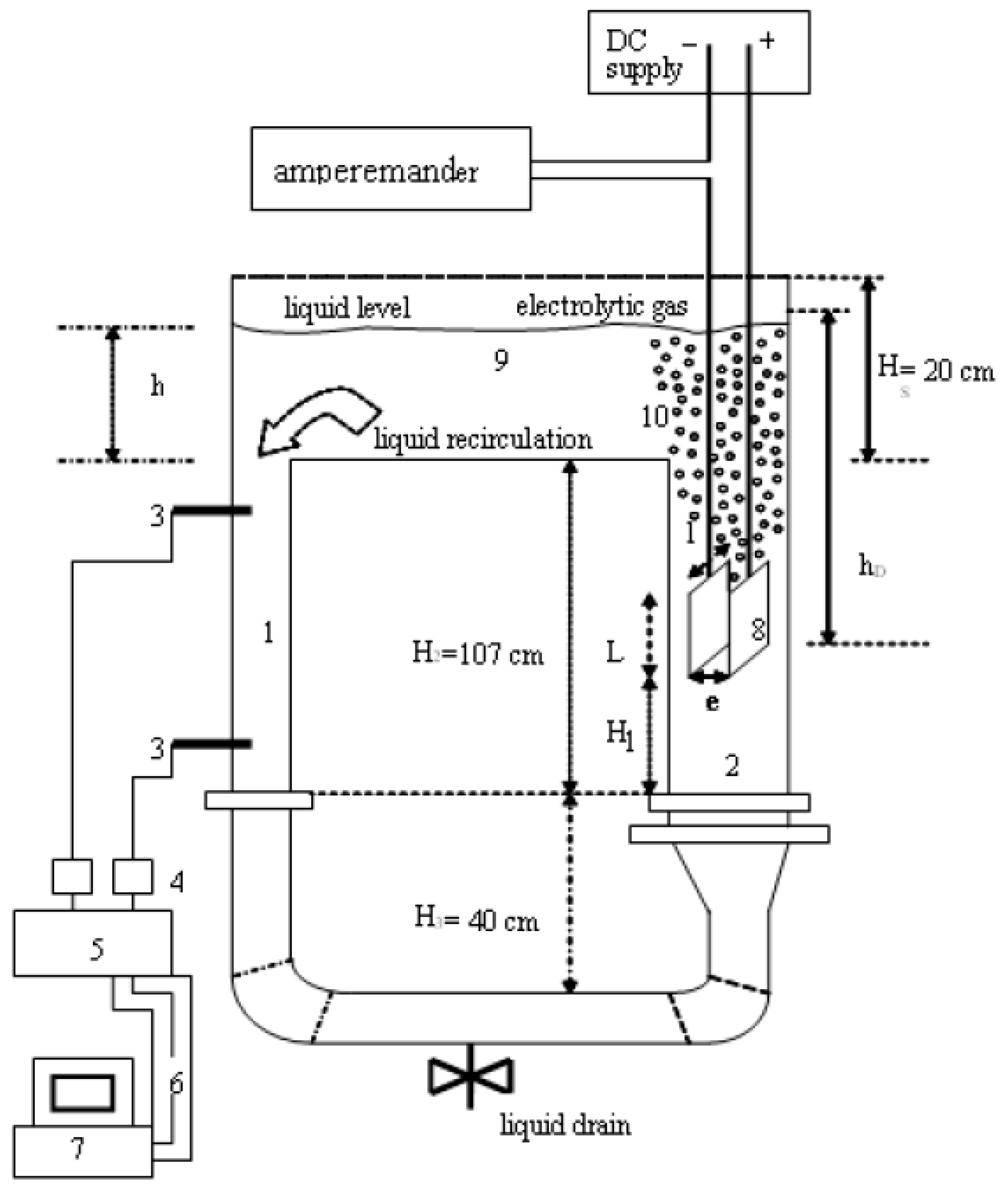
As shown in Figure 11, the reactor system integrates electrolysis with specially designed pressure filtration cells and anion exchange membranes to selectively transport arsenic and sulfate ions to the acidic anode chamber. Electrochemical ion exchange inserts layers of anion exchange resin within the chambers of the electrolysis cells to enhance sulfate removal through simultaneous adsorption and EC. EC uses mild steel anodes to generate iron hydroxides that adsorb and precipitate the arsenic anions after prior sulfate reduction. This integrated reactor achieved near-complete arsenic removal, reduced chemical additives, and reduced the alkali required for pH adjustment during the electrolysis phase, resulting in reduced sludge production. This innovation offers an environmentally friendly solution for treating complex wastewater that is not adequately treated by conventional sedimentation or coagulation alone [92]. Bennajah et al. [96] introduce a significant innovation in EC reactor design using an external air-transfer reactor as shown in Figure 12, which is much better than a conventional mechanical stirred-tank reactor.
Unlike the mechanically agitated reactor, the external air-transfer reactor shown in Figure 12 utilizes electrochemically generated hydrogen ions to stimulate natural fluid recirculation through density differences between the ascending and descending tube sections, eliminating the need for a mechanical system or external gas inputs. This configuration is the optimal combination, promoting efficient coagulant dispersion and facilitating instantaneous flotation and recovery of the jets, thus increasing the overall fluorine separation performance. Sandoval et al. [81] combined a filtration and pressure flow reactor, as shown in Figure 13, which features a three-cell stack with aluminum electrodes.
As shown in Figure 13, this design is specifically designed to simultaneously remove fluoride and arsenic from groundwater in a continuous-flow system. The filtration and pressure design suggests a compact and scalable design, while the three-cell stack allows for a larger electrode surface area in a relatively small volume, improving the efficiency of the treatment process. The reactor has proven its ability to effectively remove fluoride and arsenic simultaneously from groundwater. The reactor was used with real groundwater containing various coexisting ions and proved effectiveness in treating this complex matrix with reduced energy consumption, highlighting its cost-effective operational potential.
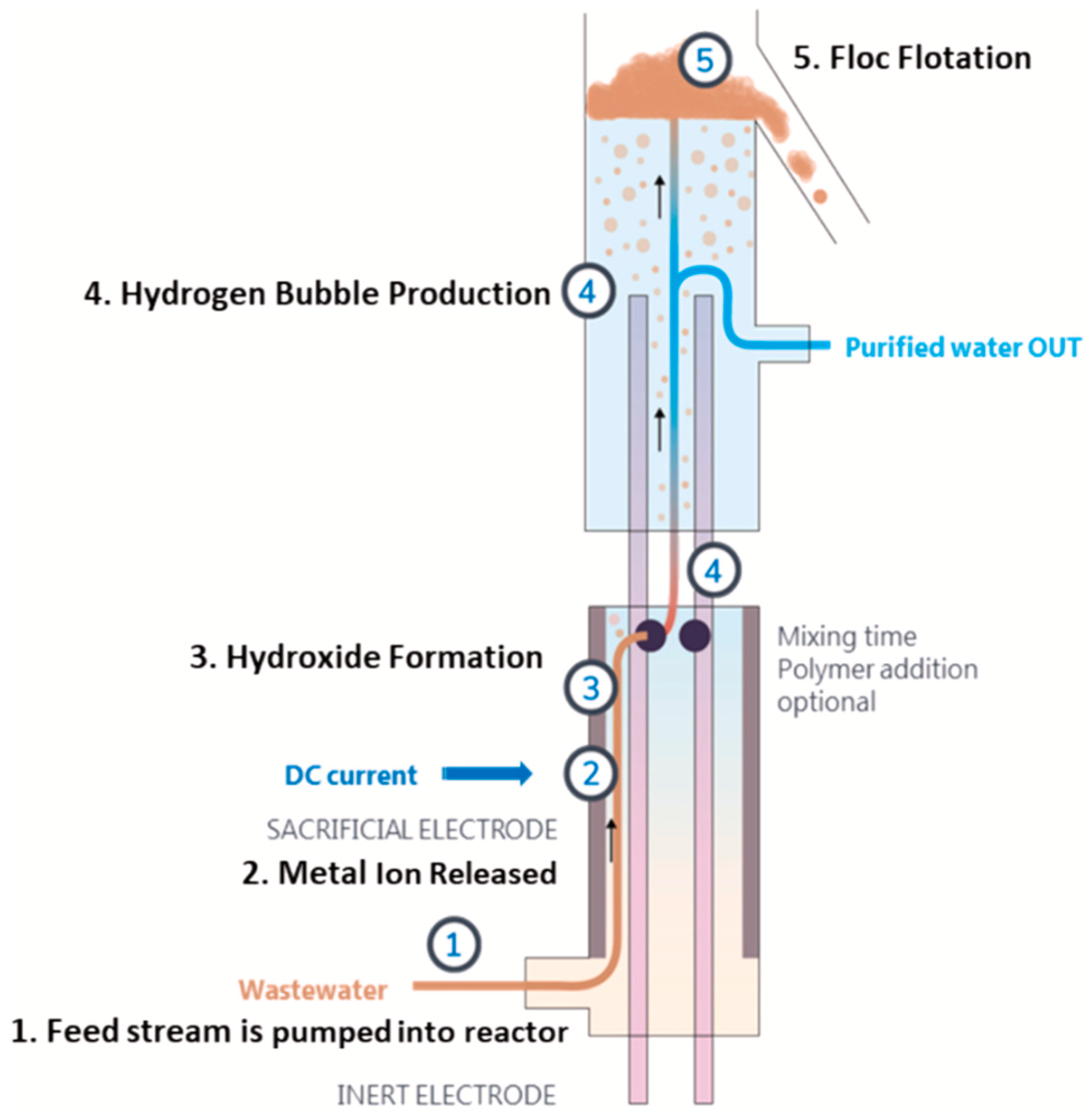
Meng et al. [93] used a process combining chemical coagulation with EC to remove fluoride at depth from tungsten smelting wastewater. This approach has evolved from a laboratory-scale test to a pilot demonstration, demonstrating its practical applicability and industrial feasibility. The combined process achieved remarkable deep fluoride removal, effectively reducing the concentration of 128 mg/L to less than 10 mg/L in pilot tests. By integrating EC as a secondary treatment step, the process significantly reduces reliance on chemical coagulants, resulting in lower operating costs and a reduced volume of secondary sludge. Furthermore, it reduces the consumption of fluoride precipitating agents, making the treatment more sustainable. The successful transition from laboratory experiments to a pilot plant demonstrates the practicality and industrial scalability of this innovative combined treatment. Jebur et al. [82] developed a novel multi-stage integrated treatment system for produced water. This system combines four distinct processes: EC as the initial treatment stage, ultrafiltration as the second stage, membrane distillation as the third stage, and crystallization as the final stage for solid waste management. Each stage effectively contributes to the overall removal of diverse contaminants. This integrated approach provides a robust solution for treating produced water, which is a particularly challenging wastewater stream due to its high salinity, diverse organic content, and other contaminants. The sequential treatment significantly reduces membrane fouling in the membrane distillation stage, thereby enhancing the overall efficiency and extending the lifespan of the membranes. Bani-Melhem et al. [79] integrated the EC process as a pretreatment step with a submerged membrane bioreactor. This integrated system is designed to operate efficiently under low voltage gradients in the EC unit, using aluminum electrodes. Thus, energy consumption is minimized. A key effect is the significant reduction and control of fouling on the membranes, which is critical to maintaining the long-term stability and efficiency of the systems. The integrated system achieves high efficiency in removing various contaminants. Additionally, electrochemical membrane pretreatment reduces the consumption of coagulant chemicals, contributing to more efficient wastewater treatment. The fouling-reducing ability of pretreatment helps extend the life of membranes, which in turn reduces maintenance and replacement costs. Lee et al. [84] implemented a reactor with efficient integration of EC with ceramic membranes. This hybrid system was specifically designed to treat complex wastewater from semiconductor industry. The integrated system demonstrates high efficiency in treating wastewater with complex composition, including dissolved silica, organic compounds, and nitrates. This integrated solution effectively addresses the limitations associated with using EC or membrane filtration technologies separately, providing a more comprehensive and efficient treatment pathway. By providing an effective and efficient way to treat one of the most challenging wastewater streams, this innovation contributes significantly to more sustainable manufacturing practices in the semiconductor sector. Dong et al. [32] designed a coaxial tubular electrocoagulation-flotation reactor designed for continuous slurry processing as shown in Figure 14.
As indicated by Figure 14, this uniquely integrated reactor combines EC and flotation in a single unit by using concentric tubular electrodes (aluminum outer anode and stainless steel inner cathode). The vertical system allows for simultaneous coagulant (Al3+) generation, hydrogen bubble production, and efficient composite flotation, which is subsequently separated in a coagulation tower located directly above the analytical cell. This integrated EC-F system achieved a silica removal efficiency of 88% under ideal conditions, while maintaining a low operating cost. This compact, continuous-flow design significantly reduced the potential for fouling in reverse osmosis (RO) membranes, extending their lifespan and reducing the need for chemical cleaning. The axial reactor design ensures uniform flow distribution and efficient contaminant interaction, while its flotation capability improves sludge separation and water purity. Compared to other technologies, this design provides a highly effective, sustainable, and economical approach to industrial-scale silica removal from complex waste streams.
The study conducted by Waghe et al. [86] explores the integration of EC with filtration and adsorption processes in continuous operation, focusing on the effect of different electrode configurations (Al–Fe–Al–Fe, Fe–Al–Fe–Al, Al–Al–Al–Al, and Fe–Fe–Fe–Fe) on contaminant removal efficiencies. Among the tested configurations, the Al–Fe–Al–Fe electrode arrangement showed the best performance and economic feasibility. Furthermore, the integrated EC filtration system demonstrated superior cost-effectiveness compared to conventional EC treatments. Same observations were reported by Isawi et al. [88] who combined EC with flotation and membrane processes. EC pretreatment achieved high efficiency while significantly reducing membrane fouling, enabling stable and efficient desalination. Overall, the incorporation of EC as a pretreatment step proved significant in improving the overall performance and sustainability of the membrane-based systems. These hybrid designs not only improve contaminant removal but also extend membrane life, reduce operating costs, and open the possibility of reusing treated wastewater, making them effective tools for treating complex industrial waste in sectors such as semiconductor manufacturing and textiles. García et al. [89] designed a pilot system that includes an innovative multistage electrochemical reactor with a spiral up-flow design, incorporating aluminum and iron electrodes for on-site coagulant generation, as shown in Figure 15.
The key innovations shown in Figure 15 include a flow distributor and inlet turbulence inducer to improve fluid dynamics and coagulant dispersion. The system is connected to a horizontal coagulant-sedimentation unit designed with internal filters and controlled flow paths to promote coagulant growth, uniform distribution, and efficient separation of sludge from the filtered water. This innovative configuration resulted in improved contaminant removal, uniform flow distribution, and continuous and scalable treatment performance with improved retention times for both coagulation and sedimentation.
Channa et al. [87] developed a novel integrated electrocoagulation–filtration system, combining an EC unit with an ultrafiltration membrane filter. The system achieved 99% arsenic removal in just 5 min. Shahedi et al. [90] presented an integration of photo-electrocoagulation with advanced in situ oxidation in a continuous-flow reactor for the treatment of real effluents from a gold processing plant. The system uniquely combines EC, UV–LED radiation, and in situ ozone generation in a single unit. This design uses Fe–SS anodes and Gr–Al cathodes without injecting external oxidants. This integrated reactor achieved complete removal of cyanide and copper with minimal sludge production. The synergistic effects of coagulant formation, ozone, hydroxyl radicals, and superoxide generated a highly oxidative environment capable of degrading strong metal-cyanide complexes. This reactor significantly improves contaminant removal efficiency, especially in complex wastewater systems, while eliminating the need for added chemical oxidants, thereby reducing operating costs and environmental impact. Penafiel et al. [101] combined EC with photocatalysis assisted by titanium dioxide (TiO2), creating a synergistic process capable of effectively treating wastewater containing both organic and inorganic pollutants. EC plays a key role in removing heavy metals and other inorganic pollutants by generating metal hydroxide clusters that adsorb and precipitate metal ions such as lead, cadmium, and chromium. Meanwhile, TiO2 photocatalysis, activated by UV light, produces reactive oxygen species that oxidize and degrade organic compounds. Combining these two processes improves overall treatment efficiency by accelerating pollutant removal, enhancing metal precipitation, and reducing residual pollutant concentrations. This hybrid system has demonstrated high removal efficiencies for both organic matter and inorganic contaminants, providing a robust solution for treating complex industrial wastewater streams while minimizing sludge generation and energy consumption. Liu et al. [91] designed an advanced hybrid system combining EC and novel bilayer nanofiltration membranes for the separation of lithium (Li+) and magnesium (Mg+) with high selectivity in complex salt-lake brines. The innovation lies in the synergistic integration of a specially designed membrane and bilayer nanofiltration technology. Integrating EC with membrane filtration, improves separation selectivity and reduces fouling on the membrane, enabling more efficient and stable operation.
Future innovations in EC systems should focus on the development of integrated treatment systems that combine EC with advanced processes such as membrane filtration, adsorption, and advanced oxidation. Emphasis should be placed on the design of smart reactors with real-time monitoring and AI-based control to improve efficiency and adaptability. Advances in electrode materials can improve durability and selectivity, while the integration of renewable energy sources, such as solar, can enhance sustainability. Table 6 shows that some of these innovations include reactor geometry, electrode configuration, flow management, mixing strategies, and operational scalability.
Table 6 provides a comprehensive overview of various innovative EC-based hybrid systems and their design modifications, illustrating how the combination of EC with other physical, chemical, and membrane processes improves treatment performance in various applications. Each entry describes a specific combined system, highlights its unique design innovation, and summarizes its impact on treatment efficiency, operating costs, scalability, and sustainability. Synergistic designs enable improved mass transfer, enhanced contaminant removal, reduced sludge production, reduced membrane fouling, and lower chemical and energy consumption. It is worth noting that these systems are highly scalable, making them suitable for practical industrial and environmental applications, such as treating groundwater, wastewater from the mining or semiconductor industries, and separating brine from salt lakes.

6. Scale-Up of Continuous EC Processes

EC has shown high effectiveness in removing inorganic pollutants such as heavy metals, suspended solids, and certain anions from water [89,93]. In this section, a comprehensive analysis of those scale-up challenges highlights case studies of both successful and problematic scale-up attempts, examines cost and feasibility aimed at enabling large-scale continuous EC processes for industrial inorganic pollutant treatment.

6.1. Technical Challenges in Scaling up EC

Scaling up EC from bench-scale tests to pilot and full-scale continuous systems is non-trivial. Several interrelated technical challenges must be addressed to ensure efficient and reliable performance at larger throughputs:
  • Electrode consumption and maintenance: Electrode consumption rates can increase non-linearly with scale if the current distribution is uneven. Furthermore, cathode passivation is exacerbated during long-term continuous operation, leading to decreased efficiency over time [89]. This requires routine cleaning or operational strategies like polarity reversal or surface agitation to maintain performance [89]. These maintenance demands pose downtime and cost challenges in large systems.
  • Current distribution and scale of electrolysis: In a large reactor, ensuring uniform current density across all electrodes and throughout the reactor volume is difficult [93]. In addition, poor current distribution can cause localized under-treatment (in zones with lower current) or excessive electrode corrosion (in zones with higher current).
  • Cost-effectiveness vs. maintenance: While EC can achieve high pollutant removal efficiencies, the increased maintenance demands at larger scales, such as frequent electrode replacement, cleaning, and system downtime, can offset its perceived cost-effectiveness. In practice, the operational expenses for electrode maintenance, energy consumption, and labor must be carefully considered when evaluating the economic feasibility of scaled-up EC systems. This highlights a critical trade-off between high removal performance and long-term operational costs [89,93].
  • Mass transfer and mixing: Achieving adequate mixing and mass transfer in large-volume reactors is a challenge. Hydrodynamics in scaled systems must ensure that coagulant species and contaminants effectively collide and aggregate. Inadequate mixing in a large tank can lead to stratification, with portions of the flow under-treated. Many industrial EC designs incorporate baffling, stirring, or pumped recirculation to promote uniform contact [89,93].
  • Solid handling and sludge management: A successful EC process generates flocculated solids (sludge) containing the removed inorganic pollutants (e.g., metal hydroxide sludge). At larger scales, the volume of sludge produced is significant, necessitating robust separation (sedimentation or filtration) and handling systems [89,93].
  • Process stability and control: Industrial wastewaters can have variable compositions and flow rates, which tests the adaptability of an EC system. Fluctuations in pollutant concentrations, pH, or conductivity can alter EC performance and may require dynamic adjustment of current or retention time. At the lab scale, conditions are easily controlled; at scale, robust monitoring and control systems are needed to maintain treatment efficiency under varying influent conditions [89,93].
  • Short and long-term stability: Some scale-up challenges have only become evident in longer pilot runs. Studies report issues like anode passivation over time, cathode deterioration due to impurities, and even microbial growth (biofilm) on electrodes in less controlled environments [89,93].
In summary, scaling up EC demands careful attention to reactor and electrical design to maintain uniform treatment, strategies to mitigate electrode fouling and consumable usage, effective handling of by-product solids, and adaptive controls to manage variable field conditions. These technical challenges, along with the trade-off between operational maintenance and cost-effectiveness, have so far limited the widespread deployment of EC as a standalone industrial treatment, despite its compelling removal capabilities at lab scale [65,89]. The next sections will explore how these challenges have manifested in real case studies and what solutions or innovations have been developed.

6.2. Case Studies: Successes and Lessons from Scale-Up

Real-world applications of EC for inorganic pollutant removal have yielded both notable successes and instructive setbacks. Here we review a few case studies, including pilot and full-scale trials, that illustrate the practical outcomes of scaling up continuous EC processes:
Landfill leachate—pilot hybrid system: Hernández et al. [102] implemented a pilot-scale EC coupled with a constructed wetland to treat landfill leachate, which contains a mix of inorganic contaminants (ammonia, heavy metals, chloride) as well as organic matter. In this two-stage system, raw leachate is first passed through an EC unit, then through a vegetated wetland bed for polishing. The results were encouraging: the hybrid pilot achieved 79.4% COD removal, 89.8% BOD removal, and substantial total suspended solids (TSS) reduction in the leachate [102]. The EC stage effectively coagulated heavy metals and colloids (reducing turbidity/color), which not only directly removed those contaminants but also improved the conditions for the subsequent wetland bio-treatment (by lowering inhibitory substances). This case demonstrates that EC can be scaled to pilot level and integrated into a treatment train, playing the role of a physical-chemical pretreatment for difficult wastewater. It also shows a successful scale-up in a continuous-flow context—the pilot treated a continuous-flow of leachate (with retention times on the order of hours) and maintained performance.
Heavy metals in plating wastewater—industrial application: EC has been piloted and used in some industries for heavy metal removal. For example, in metal-finishing/electroplating wastewater (often containing toxic metals like hexavalent chromium, nickel, copper, and zinc), EC has been found capable of reducing metal ion concentrations to well below discharge limits in industrial trials [103]. One report describes an industrial-scale EC system treating plating rinse water: using iron electrodes, the system consistently reduced influent metals (e.g., Cr, Ni) from tens of mg/L down to <1 mg/L, meeting environmental standards [103]. The advantage in such cases is that EC can handle mixed metal streams without needing a different chemical for each metal; the iron or aluminum hydroxides formed will co-precipitate a variety of metal ions simultaneously. A challenge noted was managing the high conductivity and low pH of plating wastes—these conditions accelerated electrode consumption and hydrogen gas evolution. The industrial unit had to be ruggedized (corrosion-resistant materials for the reactor vessel, ventilation for hydrogen gas) and automated pH control was implemented to maintain optimal removal (since metal hydroxide solubilities are pH-dependent).
Krystynik et al. [65] investigated the full-scale industrial application of EC for the removal of zinc (Zn) from acidic wastewater generated during fly ash treatment at a municipal waste incineration plant (Figure 16). Operating at a capacity of 1200–1400 L/h, the system employs parallel EC cells using iron electrodes to reduce Zn concentrations below 0.5 mg/L, significantly below the legal discharge limit of 1.5 mg/L. The study highlights the operational efficiency, reliability, and cost-effectiveness of EC, particularly in settings like waste-to-energy plants that generate their own electricity. The process also demonstrated the removal of other heavy metals (e.g., Pb, As, Cu), with operational costs around 1.6 EUR/m3. This work provides a strong example of industrial-scale heavy metal remediation in wastewater using EC.
Meng et al. [93] demonstrated a combined chemical coagulation and EC system for the deep removal of fluoride from tungsten smelting wastewater (TSW) in a pilot plant operating at 250–500 L/h. The pretreatment involved aluminum sulfate coagulation, reducing fluoride from ~128 to 51 mg/L. This was followed by EC using aluminum plates, which further reduced fluoride levels to below 10 mg/L. The optimal pH for both stages was found to be 6–7, and current density played a critical role in aluminum ion generation and fluoride migration. The total treatment cost ranged from 0.99 to 1.51 USD/m3, with the highest operational costs stemming from electrode consumption and sludge management. The integrated approach depicted in Figure 16 has reliable, continuous performance and highlights the feasibility of EC for fluoride removal in high-salinity metallurgical wastewater.
García et al. [89] designed and operated a novel continuous EC–flocculation–sedimentation system for the removal of arsenic, fluoride, and hydrated silica from deep well drinking water, as previously shown in Figure 15. Using hybrid aluminum–iron electrodes in a multistage flow reactor, coupled with a flocculator-settler, they achieved 100% As, 82.8% F, and 98.6% SiO2 removal at an optimal current density of 5 mA/cm2 and flow velocity of 1.31 cm/s. Operational costs were as low as 0.41 USD/m3, and detailed analysis showed formation of stable aluminosilicate and iron oxyhydroxide flocs. The design emphasized improved hydraulics and retention, providing a scalable model for decentralized water treatment in fluoride- and arsenic-affected regions.
The above case studies illustrate that successful scale-up is possible, particularly when the system is carefully optimized or integrated into a larger treatment train. High removal efficiencies for inorganic pollutants (90%+ in some cases) have been achieved at pilot and industrial scales [89]. At the same time, they reveal common hurdles: slight to moderate drops in performance when moving to continuous-flow, the need for more involved operational control (pH, cleaning cycles), and the benefits of hybrid approaches. Table 7 summarizes a few examples of EC performance at different scales for various inorganic pollutant targets, highlighting scalability metrics where available.
Table 7 shows some examples of electrocoagulation (EC) performance for inorganic pollutant removal across different scales, with key scalability metrics.
As shown in Table 7, EC can achieve high removal of inorganic pollutants across scales, but the energy consumption (kWh per cubic meter treated) and removal efficiency can vary widely with scale and wastewater characteristics. In general, simpler waste streams (e.g., single-metal or high-turbidity waters) show easier scalability, whereas complex matrices (e.g., olive mill wastewater with mixed organics and inorganics) show efficiency losses at pilot scale. The table also highlights reported treatment costs: small pilot studies have indicated costs on the order of $1.7–3 per m3 of water treated, which is competitive with or even lower than chemical coagulation in some cases [104]. These costs include both electricity and electrode materials. Notably, one techno-economic analysis found about $3 per 1000 L (=$3/m3) for a 3000 L/day EC system, and identified benefits like a short retention time and small footprint as economic advantages [104]. However, costs can escalate if energy usage is high; for instance, treating very high-strength wastewater (like undiluted olive mill effluent) can demand tens of kWh per m3, which may be economically prohibitive without optimization or renewable energy inputs.

7. Circular Economy

The circular economy (CE) model emphasizes minimizing waste and maximizing resource efficiency by transforming by-products into valuable secondary raw materials [105]. In the pursuit of sustainable water treatment technologies, EC stands out not only for its ability to remove inorganic pollutants but also for its potential to contribute meaningfully to the circular economy. Unlike many conventional or alternative treatment technologies that primarily focus on pollutant removal with limited consideration for by-product reuse, EC inherently generates recoverable materials during the treatment process. This positions EC as a dual-function technology: simultaneously treating wastewater and producing value-added outputs. Unlike traditional linear treatment approaches that generate waste for disposal, EC facilitates the valorization of waste into useful products such as nutrients, catalysts, metals, and energy carriers, as shown in Figure 17.
This approach, shown in Figure 17, is especially advantageous in continuous EC systems, which offer scalability and efficiency for industrial wastewater streams rich in inorganic contaminants. In comparison to other techniques, EC’s ability to integrate resource recovery directly within the treatment process differentiates it as a more holistic, circular approach. The following sections highlight key valorization strategies supported by recent research.

7.1. Nutrient Recovery

Recent studies have demonstrated EC’s ability to recover nutrients from waste streams. For example, researchers successfully produced ferrous ammonium phosphate (FAP) from source-separated urine by optimizing parameters like current density (100–300 A/m2), initial pH (5–9), and reaction time (2–6 h) using the Box–Behnken statistical design. Under optimal conditions (pH 7, current density 100 A/m2, and 4 h reaction time), the EC process achieved 70% ammonium precipitation, 56.4% COD removal, and significant phosphate recovery. Characterization of the recovered product using XRD, SEM, and EDX confirmed the formation of crystalline FAP particles. Although this study was conducted in batch mode, it highlights the potential for nutrient recovery that could be scaled in continuous systems, further illustrating EC’s unique integration of treatment and resource reclamation, in contrast to conventional chemical precipitation or biological nutrient removal, which often lack simultaneous pollutant management [106].

7.2. Adsorbents and Catalysts

EC sludge containing metal oxides like Fe2O3 and Al2O3 can be reused as adsorbents and heterogeneous catalysts. For example, Sharma et al. [107] demonstrated the use of EC sludge in photoelectrocatalytic water splitting, where the iron oxide-rich sludge achieved notable photocurrent densities. This showcases the potential of sludge reuse as catalysts or adsorbents, aligning with waste valorization principles.

7.3. Advanced Material Production

EC by-products can be processed into advanced materials for industrial applications. A notable example involves transforming aluminum-based sludge into mesoporous alumina microcapsules (MAMs) for corrosion protection. These MAMs encapsulate corrosion inhibitors like 8-hydroxyquinoline and benzotriazole, which are released on demand within polymer coatings. Electrochemical impedance spectroscopy confirmed the enhanced corrosion resistance. While this study is based on batch-generated EC sludge, it exemplifies how even lab-scale EC systems can produce valuable by-products, supporting the circular economy through material innovation [108]. This direct conversion of treatment by-products into functional materials highlights EC’s advantage over other treatment techniques that generate non-recoverable sludge, underlining its distinct contribution to the circular economy.

7.4. Metal Recovery from Wastewater

EC’s capacity for recovering valuable metals has been demonstrated across various studies. Zhang et al. [109] demonstrated the feasibility of using EC with aluminum electrodes to recover over 95% of lithium ions from model brine solutions. The optimal performance was achieved at 76.9 mA/cm2, pH 6.45, and 150 min reaction time, with a low energy consumption of 0.064 kWh/g Li. The recovery mechanism was primarily driven by co-precipitation with Al(OH)3, confirmed by multiple characterization techniques (XRD, FTIR, SEM-EDS, XPS). This study highlights EC as an economical and scalable approach for inorganic resource recovery from brines, supporting circular economy principles through waste-to-resource transformation. Similarly, Li et al. [110] developed an enhanced EC system for the removal and recovery of uranium from wastewater by incorporating ligand chelation (Alizarin S) into the process. Using iron anodes, the method promoted the formation of stable uranyl-chelate complexes, which facilitated efficient precipitation. The resulting flocs were subsequently processed through an oxidative elution step followed by ammonia precipitation, yielding yellowcake heavy uranium amide with an overall uranium recovery efficiency of 89.71%. This semi-batch system was designed with practical scalability in mind, demonstrating an integrated EC-based approach combining treatment and selective resource recovery, aligning well with circular economy principles in nuclear wastewater management. Additionally, Mehdipoor and Moosavirad [111] achieved over 90% Cu recovery from industrial wastewater using EC, proposing its use in mineral processing. Although conducted in batch mode, this study provides a strong case for copper recovery with potential for continuous process adaptation.

7.5. Hydrogen Generation for Energy Recovery

EC also produces hydrogen gas at the cathode during water reduction, presenting a promising waste-to-energy pathway. Sharma et al. [112] demonstrated that using Fe–Al electrodes in a batch reactor could remove significant pollutants while generating hydrogen, with a low energy input. This dual-function capability, generating energy while treating wastewater, is rarely achieved by conventional water treatment techniques, reinforcing EC’s unique role in circular economy systems.
Continuous EC systems offer a versatile platform for circular water treatment, recovering resources, producing energy, and reducing waste. However, gaps remain, such as the need for integrated systems that combine sludge valorization, metal recovery, and hydrogen capture at scale. Standardized methods for assessing system circularity and comprehensive life-cycle analyses are also lacking. Future research should focus on fully integrated, scalable EC platforms that leverage their distinct dual treatment-resource recovery capability, fully realizing the potential of the circular economy in inorganic wastewater management.

8. SWOT Analysis of CEPs

To consolidate the findings of this review and provide a structured perspective on the future of CEPs for industrial inorganic pollutant treatment, a SWOT (strengths, weaknesses, opportunities, and challenges) analysis was conducted (Figure 18).
  • Strengths: CEPs achieve high removal efficiencies for a wide range of inorganic contaminants, with advantages such as lower sludge generation, reduced chemical consumption, and compatibility with renewable energy sources. It also offers potential for resource recovery, supporting circular economy strategies.
  • Weaknesses: Limitations include electrode passivation, relatively high energy demand at large scale, lack of standardized reactor designs, and performance variability across wastewater matrices. Furthermore, most applications remain at laboratory scale, with limited pilot or industrial demonstrations.
  • Opportunities: CEPs can be integrated with complementary treatment technologies (e.g., membrane processes, flotation, advanced oxidation) and benefit from ongoing innovations in electrode design, hydrodynamics, and automation. The growing demand for sustainable wastewater treatment solutions, coupled with advancements in modeling, optimization, and AI-driven control, creates further potential for industrial adoption.
  • Challenges: Major barriers include electrode fouling and maintenance, scaling from laboratory to industrial scale, economic feasibility, and regulatory uncertainty in certain regions [113]. The lack of long-term operational data also poses a challenge for commercialization and standardization [114].
Figure 18 presents a visual summary of this SWOT analysis, providing readers with a concise overview of CEPs’ current position and the critical areas requiring attention for their successful industrial-scale implementation.

9. Conclusions

CEPs have emerged as a promising and adaptable technique for the treatment of industrial wastewater containing inorganic pollutants. This review comprehensively assessed the performance of standalone and combined CEPs systems, design innovations, mathematical modeling approaches, and operational optimization methods. The findings confirm that CEPs can achieve high removal efficiencies for a wide spectrum of inorganic contaminants such as fluoride, arsenic, heavy metals (e.g., Cr, Pb, Ni, Fe), nitrates, and phosphates under optimized operating conditions.
Compared to conventional treatment methods, CEPs offer numerous advantages, including simplified operation, reduced chemical usage, lower sludge production, and ease of integration with renewable energy sources and complementary processes such as membrane filtration, flotation, and advanced oxidation. Furthermore, innovations in reactor design, such as internal mixing, electrode geometry, and modular configurations, have contributed to improved performance, scalability, and operational stability.
Mathematical modeling and optimization techniques, including kinetic/isotherm models, residence time distribution (RTD), computational fluid dynamics (CFD), and response surface methodology (RSM), have enhanced the understanding of system dynamics and facilitated process scale-up. Machine learning applications such as Gradient Boosting Machines (GBMs) are beginning to show promise in predicting system behavior and informing cost-effective operational strategies.
Nevertheless, despite the technological advancements and positive performance results, the large-scale implementation of CEPs remains limited. Key challenges include the lack of standardized reactor designs, variability in operational conditions across different wastewater types, electrode passivation, energy consumption under high throughput, and limited long-term field data. Additionally, the limited number of modeling and optimization studies for combined CEPs systems highlights the need for further research in integrated approaches.
Recent research trends in continuous electrocoagulation processes (CEPs) demonstrate increasing emphasis on reactor and electrode design innovations, integration with complementary treatment technologies, and the application of modeling and artificial intelligence for process optimization and scale-up. These trends reflect growing efforts to bridge the gap between laboratory investigations and industrial practice, while also aligning with global demands for sustainable and resource-efficient water treatment technologies. Despite these advancements, significant knowledge gaps remain. The absence of standardized reactor configurations and design protocols hampers cross-comparison of results and scalability. Long-term pilot- and full-scale validation studies are still scarce, leaving questions about durability, maintenance, and cost-effectiveness under real operating conditions. Moreover, research on modeling and optimization of combined CEPs systems is particularly limited, constraining predictive design and large-scale implementation. Finally, supportive regulatory frameworks and techno-economic analyses are needed to enable widespread industrial adoption. As summarized in the SWOT analysis (Section 8), addressing these gaps is essential for unlocking CEPs’ full potential as a reliable, scalable, and sustainable technology for industrial wastewater treatment.
In summary, CEPs are a viable, flexible, and potentially sustainable solution for industrial inorganic wastewater treatment. Its successful transition from lab to industrial scale will depend on systematic research, process standardization, long-term validation, and supportive regulatory and economic frameworks.

10. Recommendations for Future Work

Based on the insights gathered from this comprehensive review, several recommendations can be made to guide future research and industrial development of continuous EC technologies:
Develop and adopt standardized guidelines for CEPs reactor design to ensure comparability of performance data, facilitate scale-up, and reduce design-related uncertainties in full-scale applications.
Conduct more pilot-scale and full-scale studies under real industrial conditions using complex wastewater matrices to validate laboratory findings, evaluate long-term stability, and assess maintenance requirements.
Expand the use of dynamic modeling (e.g., CFD, AI/ML, process simulation) to capture the coupled electrochemical, hydraulic, and mass transfer phenomena in CEPs. Experimental validation of these models will permit their use to design adaptive control strategies for real-time optimization.
Explore the systematic integration of CEPs with other treatment technologies such as reverse osmosis, membrane bioreactors, ion exchange, and advanced oxidation processes. This includes evaluating synergies in performance, energy use, and cost reduction.
Investigate novel and sustainable electrode materials (e.g., coated, composite, or recycled electrodes) that can reduce passivation, enhance electrochemical activity, and extend electrode lifespan.
Emphasize CEPs’ potential for resource recovery—such as phosphorus, metals, and reusable water—within a circular economy framework. Life-cycle assessments (LCA) and techno-economic analyses (TEA) should be performed to support such implementations.
Focus on reducing operational costs by optimizing current density, residence time, and flow rates, and by employing energy recovery systems or solar-powered configurations for decentralized applications.
Undertake detailed environmental impact studies and collaborate with regulatory agencies to develop safety and compliance standards that encourage the adoption of CEPs in industrial practice.
Establish a centralized, open access database that compiles performance data, cost metrics, energy consumption, and modeling results of CEP systems across different applications to support meta-analysis and informed decision-making.

Author Contributions

Conceptualization, Z.A.-Q. and E.A.; methodology, Z.A.-Q., M.A.-S. and K.B.-M.; formal analysis, Z.A.-Q., M.A.-S., M.M.A.-R., K.B.-M. and E.D.; investigation, Z.A.-Q., M.A.-S., M.M.A.-R., K.B.-M. and E.D.; resources, Z.A.-Q., E.A., M.A.-S., M.M.A.-R., K.B.-M. and E.D.; data curation, Z.A.-Q., E.A., M.A.-S., M.M.A.-R., K.B.-M. and E.D.; writing—original draft, Z.A.-Q., M.A.-S., M.M.A.-R., K.B.-M. and E.D.; writing—review and editing, Z.A.-Q., M.A.-S., M.M.A.-R., K.B.-M. and E.D. All authors have read and agreed to the published version of the manuscript.

Funding

This research received no external funding.

Data Availability Statement

The original contributions presented in this study are included in the article. Further inquiries can be directed to the corresponding authors.

Conflicts of Interest

The authors declare no conflicts of interest.

Abbreviations

AAnode
ACAlternating current
ACAActivated Carbon Adsorption
AIArtificial Intelligence
AlAluminum
AREAverage relative error
AUDAustralian dollars
BBDBox–Behnken Design
BOD5Biochemical Oxygen Demand after 5 Days
Br-Bromide ion
CCrystallization, Cathode
CADCanadian dollars
CCChemical Coagulation
CCDCentral Composite Design
CDCurrent Density
CECircular economy
CEPsContinuous Electrocoagulation Processes
CFDComputational fluid dynamics
Cl-Chloride ion
CoThe initial concentration of the pollutants before treatment
CrChromium
CtThe concentration of the pollutants after treatment
CTVConversion Time Kinetics
CuCopper
DDiameter
DCDirect current
EEnergy Consumption
ECElectrocoagulation
ECFElectrocoagulation/Flotation
ECTElectrocoagulation time
EDIElectrochemical Oxidation Index
ED-ECElectro-Disinfection–Electrocoagulation
EFloElectro-flotation
ElElectrolysis
EOElectrooxidation
EUREuro
FFiltration
FeIron
FloFloatation
FluFluctuation
FPFilter Press
GBMGradient Boosting Machine
GeGraphite
IThe applied current
IEIon Exchange
LCALife Cycle Assessment
Li Lithium
mAmount of dissolved anode
MAMsMesoporous alumina microcapsules
MDMembrane Distillation
MFMicrofiltration
MgMagnesium
MLMachine learning
MnManganese
MwThe molecular weight of electrode material
nElectrode Number
NFNano Filtration
NH3-NAmmonia Nitrogen
NiNickel
NTUNephelometric Turbidity Unit
OOOzone Oxidation
RRemoval efficiency
R2Regression correlation coefficient
ROReverse osmosis
RSMResponse Surface Methodology
RTDResidence Time Distribution
SSedimentation
SEECSpecific Electrical Energy Consumption
SFSand Filtration
SMBRSubmerged Membrane Bioreactor
SSStainless Steel
StSteel
SWOTStrengths, Weaknesses, Opportunities, and Challenges
TTemperature
tElectrocoagulation time
TiTitanium
TDSTotal Dissolved Solids

References

  1. Al-Ananzeh, N.; Bani-Melhem, K.; Khasawneh, H.E.; Tawalbeh, M.; Al-Qodah, Z.; Al-Bodour, A. Investigating the potential of using solid waste generated from stone cutting factories for phenol removal from wastewater: A study of adsor ption kinetics and isotherms. Results Eng. 2023, 20, 101404. [Google Scholar] [CrossRef]
  2. Zeghioud, H.; Fryda, L.; Djelal, H.; Assadi, A.; Kane, A. A comprehensive review of biochar in removal of organic pollutants from wastewater: Characterization, toxicity, activation/functionalization and influencing treatment factors. J. Water Process Eng. 2022, 47, 102801. [Google Scholar] [CrossRef]
  3. Idris, A.O.; Orimolade, B.; Dennany, L.; Mamba, B.; Azizi, S.; Kaviyarasu, K.; Maaza, M. A Review on Monitoring of Organic Pollutants in Wastewater Using Elect rochemical Approach. Electrocatalysis 2023, 14, 659–687. [Google Scholar] [CrossRef]
  4. Kumar, V.; Sharma, M.; Sondhi, S.; Kaur, K.; Sharma, D.; Sharma, S.; Utreja, D. Removal of Inorganic Pollutants from Wastewater: Innovative Technologies and Toxicity Assessment. Sustainability 2023, 15, 16376. [Google Scholar] [CrossRef]
  5. Gomaa, H.E.; Alotaibi, A.A.; Gomaa, F.A.; Bajuayfir, E.; Ahmad, A.; Alotaibi, K.M. Integrated ion exchange-based system for nitrate and sulfate removal f rom water of different matrices: Analysis and optimization using respo nse surface methodology and Taguchi experimental design techniques. Process Saf. Environ. Prot. 2021, 153, 500–517. [Google Scholar] [CrossRef]
  6. Banu, H.A.T.; Karthikeyan, P.; Meenakshi, S. Synthesis and characterization of Ce(III) decorated Duolite resin and its removal performance of toxic anions from aqueous solutions. Environ. Chem. Ecotoxicol. 2021, 3, 8–16. [Google Scholar] [CrossRef]
  7. Xiang, H.; Min, X.; Tang, C.-J.; Sillanpää, M.; Zhao, F. Recent advances in membrane filtration for heavy metal removal from wastewater: A mini review. J. Water Process Eng. 2022, 49, 103023. [Google Scholar] [CrossRef]
  8. Cevallos-Mendoza, J.; Amorim, C.; Rodríguez-Díaz, J.; Montenegro, M. Removal of Contaminants from Water by Membrane Filtration: A Review. Membranes 2022, 12, 570. [Google Scholar] [CrossRef]
  9. El-Baz, A.; Hendy, I.; Dohdoh, A.; Srour, M. Adsorption technique for pollutants removal; current new trends and fu ture challenges—A Review Egypt. Int. J. Eng. Sci. Technol. Ogy 2020, 32, 1–24. [Google Scholar]
  10. Al-Qodah, Z.; Dweiri, R.; Khader, M.; Al-Sabbagh, S.; Al-Shannag, M.; Qasrawi, S.; Al-Halawani, M. Processing and characterization of magnetic composites of activated carbon, fly ash, and beach sand as adsorbents for Cr(VI) removal. Case Stud. Chem. Environ. Eng. 2023, 7, 100333. [Google Scholar] [CrossRef]
  11. Al-Shannag, M.; Al-Qodah, Z.; Nawasreh, M.; Al-Hamamreh, Z.; Bani-Melhem, K.; Alkasrawi, M. On the performance of Ballota undulata biomass for the removal of cadm ium(II) ions from water. Desalin. WATER Treat. 2017, 67, 223–230. [Google Scholar] [CrossRef]
  12. Razzak, S.A.; Faruque, M.O.; Alsheikh, Z.; Alsheikhmohamad, L.; Alkuroud, D.; Alfayez, A.; Hossain, S.M.Z.; Hossain, M.M. A comprehensive review on conventional and biological-driven heavy met als removal from industrial wastewater. Environ. Adv. 2022, 7, 100168. [Google Scholar] [CrossRef]
  13. Guleria, A.; Kumari, G.; Lima, E.C.; Ashish, D.K.; Thakur, V.; Singh, K. Removal of inorganic toxic contaminants from wastewater using sustaina ble biomass: A review. Sci. Total Environ. 2022, 823, 153689. [Google Scholar] [CrossRef]
  14. Dawam, M.; Gobara, M.; Oraby, H.; Zorainy, M.Y.; Nabil, I.M. Advances in Membrane Technologies for Heavy Metal Removal from Polluted Water: A Comprehensive Review. Water Air Soil Pollut. 2025, 236, 461. [Google Scholar] [CrossRef]
  15. Ahmed, S.F.; Mofijur, M.; Parisa, T.A.; Islam, N.; Kusumo, F.; Inayat, A.; Le, V.G.; Badruddin, I.A.; Khan, T.M.Y.; Ong, H.C. Progress and challenges of contaminate removal from wastewater using m icroalgae biomass. Chemosphere 2022, 286, 131656. [Google Scholar] [CrossRef]
  16. Satyam, S.; Patra, S. Innovations and challenges in adsorption-based wastewater remediation: A comprehensive review. Heliyon 2024, 10, e29573. [Google Scholar] [CrossRef]
  17. Lin, J.-Y.; Tseng, T.-W. Electrochemical synthesis of magnetite nanoparticles for decentralized arsenic removal and recovery from synthetic groundwater. Sep. Purif. Technol. 2025, 376, 133976. [Google Scholar] [CrossRef]
  18. Nee Kew, S.Y.; Lau, S.Y. Review of electrochemical reactors for the efficient removal of heavy metals from wastewater. J. Ind. Eng. Chem. 2025, S1226086X25003107. [Google Scholar] [CrossRef]
  19. Lee, J.; Antonini, G.; Al-Omari, A.; Muller, C.; Mathew, J.; Bell, K.; Pearce, J.M.; Santoro, D. Electrochemical Methods for Nutrient Removal in Wastewater: A Review o f Advanced Electrode Materials, Processes, and Applications. Sustainability 2024, 16, 9764. [Google Scholar] [CrossRef]
  20. Al-Qodah, Z.; Al-Shannag, M.; Bani-Melhem, K.; Assirey, E.; Yahya, M.A.; Al-Shawabkeh, A. Free radical-assisted electrocoagulation processes for wastewater treatment. Environ. Chem. Lett. 2018, 16, 695–714. [Google Scholar] [CrossRef]
  21. Bani-Melhem, K.; Al-Shannag, M.; Alrousan, D.; Al-Kofahi, S.; Al-Qodah, Z.; Al-Kilani, M.R. Impact of soluble COD on grey water treatment by electrocoagulation te chnique. Desalin. Water Treat. 2017, 89, 101–110. [Google Scholar] [CrossRef]
  22. Merzouk, B.; Gourich, B.; Sekki, A.; Madani, K.; Vial, C.; Barkaoui, M. Studies on the decolorization of textile dye wastewater by continuous electrocoagulation process. Chem. Eng. J. 2009, 149, 207–214. [Google Scholar] [CrossRef]
  23. Bani-Melhem, K.; Alnaief, M.; Al-Qodah, Z.; Al-Shannag, M.; Elnakar, H.; AlJbour, N.; Alu’dAtt, M.; Alrosan, M.; Ezelden, E. On the performance of electrocoagulation treatment of high-loaded gray water: Kinetic modeling and parameters optimization via response surf ace methodology. Appl. Water Sci. 2025, 15, 114. [Google Scholar] [CrossRef]
  24. Al-Shannag, M.; Al-Qodah, Z.; Bani-Melhem, K.; Qtaishat, M.R.; Alkasrawi, M. Heavy metal ions removal from metal plating wastewater using electrocoagulation: Kinetic study and process performance. Chem. Eng. J. 2015, 260, 749–756. [Google Scholar] [CrossRef]
  25. Kadier, A.; Al-Qodah, Z.; Akkaya, G.K.; Song, D.; Peralta-Hernández, J.M.; Wang, J.-Y.; Phalakornkule, C.; Bajpai, M.; Muhammad Niza, N.; Gilhotra, V.; et al. A state-of-the-art review on electrocoagulation (EC): An efficient, em erging, and green technology for oil elimination from oil and gas indu strial wastewater streams. Case Stud. Chem. Environ. Eng. 2022, 6, 100274. [Google Scholar] [CrossRef]
  26. Oktiawan, W.; Sarminingsih, A.; Hadiwidodo, M.; Purwono, P. Electrocoagulation process for phosphate recovery of agricultural wastewater: Effect of calcium adding, voltage, and time. Environ. Monit. Assess. 2024, 196, 842. [Google Scholar] [CrossRef]
  27. Rakhmania; Kamyab, H.; Yuzir, M.A.; Abdullah, N.; Quan, L.M.; Riyadi, F.A.; Marzouki, R. Recent applications of the electrocoagulation process on agro-based in dustrial wastewater: A review. Sustainability 2022, 14, 1985. [Google Scholar] [CrossRef]
  28. Bani-Melhem, K.; Al Bsoul, A.; Al-Qodah, Z.; Al-Ananzeh, N.; Al-Kilani, M.R.; Al-Shannag, M.; Bani-Salameh, W. Impact of a Sand Filtration Pretreatment Step on High-Loaded Greywater Treatment by an Electrocoagulation Technique. Water 2023, 15, 990. [Google Scholar] [CrossRef]
  29. Jamrah, A.; Al-Zghoul, T.M.; Al-Qodah, Z.; Al-Karablieh, E. Performance of Combined Olive Mills Wastewater Treatment System: Electrocoagulation-Assisted Adsorption as a Post Polishing Sustainable Process. Water 2025, 17, 1697. [Google Scholar] [CrossRef]
  30. Al-Qodah, Z.; Al-Shannag, M.; Hudaib, B.; Bani-Salameh, W.; Shawaqfeh, A.T.; Assirey, E. Synergy and enhanced performance of combined continuous treatment processes of pre-chemical coagulation (CC), solar-powered electrocoagulation (SAEC), and post-adsorption for Dairy wastewater. Case Stud. Chem. Environ. Eng. 2025, 11, 101183. [Google Scholar] [CrossRef]
  31. Bani-Melhem, K.; Elektorowicz, M. Development of a novel submerged membrane electro-bioreactor (SMEBR): Performance for fouling reduction. Environ. Sci. Technol. 2010, 44, 3298–3304. [Google Scholar] [CrossRef] [PubMed]
  32. Al-Qodah, Z.; Tawalbeh, M.; Al-Shannag, M.; Al-Anber, Z.; Bani-Melhem, K. Combined electrocoagulation processes as a novel approach for enhanced pollutants removal: A state-of-the-art review. Sci. Total Environ. 2020, 744, 140806. [Google Scholar] [CrossRef]
  33. Al-Qodah, Z.; Al-Shannag, M.; Hudaib, B.; Bani-Salameh, W. Enhancement of dairy wastewater treatment efficiency in batch chemical-assisted solar-powered electrocoagulation-adsorption system. Case Stud. Chem. Environ. Eng. 2024, 9, 100760. [Google Scholar] [CrossRef]
  34. Lin, X.; Gong, J.; Li, H.; Zhang, H.; Yu, Y.; Tan, W. Solar-powered electrocoagulation treatment of wet flue gas desulfurization wastewater using dimensionally stable anode and induced electrode. Environ. Eng. Res. 2022, 28, 210590–210596. [Google Scholar] [CrossRef]
  35. Achagri, G.; Ismail, R.; Kadier, A.; Ma, P.-C. A solar-powered electrocoagulation process with a novel CNT/silver nanowire coated basalt fabric cathode for effective oil/water separation: From fundamentals to application. J. Environ. Manag. 2025, 375, 124289. [Google Scholar] [CrossRef]
  36. Boulanouar, L.; Louhichi, B.; Hamdi, W.; Jellali, S.; L’taief, B.; Hamdi, N.; Rebouh, N.; Houas, A. Parametric study of cadmium and nickel removal from synthetic and actu al industrial wastewater industry by electrocoagulation using solar en ergy. J. Water Process Eng. 2025, 71, 107261. [Google Scholar] [CrossRef]
  37. Bani-Melhem, K.; Al-Kilani, M.R.; Tawalbeh, M. Evaluation of scrap metallic waste electrode materials for the application in electrocoagulation treatment of wastewater. Chemosphere 2023, 310, 136668. [Google Scholar] [CrossRef]
  38. Nippatla, N.; Philip, L. Electrochemical process employing scrap metal waste as electrodes for dye removal. J. Environ. Manag. 2020, 273, 111039. [Google Scholar] [CrossRef]
  39. Yang, W.; Zhou, M.; Ma, L. A continuous flow-through system with integration of electrosorption and peroxi-coagulation for efficient removal of organics. Chemosphere 2021, 274, 129983. [Google Scholar] [CrossRef]
  40. Ammar, M.; Yousef, E.; Ashraf, S.; Baltrusaitis, J. Removal of Inorganic Pollutants and Recovery of Nutrients from Wastewa ter Using Electrocoagulation: A Review. Separations 2024, 11, 320. [Google Scholar] [CrossRef]
  41. Salinas-Echeverría, D.D.; Sánchez-De La Cruz, L.C.; Zambrano-Intriago, L.A.; Rodríguez-Díaz, J.M.; Sanoja-Lopez, K.A.; Luque, R.; Fernández-Andrade, K.J.; Salcedo, Y.G.; Crespo, R.J.B. Evaluation of a continuous flow electrocoagulation reactor for turbidi ty removal from surface water. Chem. Eng. Res. Des. 2023, 198, 478–488. [Google Scholar] [CrossRef]
  42. Hayden, J.; Abbassi, B. Continuous Flow Electrocoagulation System for Enhanced Phosphorous Rem oval in Decentralized Wastewater Treatment Systems. Water 2025, 17, 202. [Google Scholar] [CrossRef]
  43. Abdulhadi, B.; Kot, P.; Hashim, K.; Shaw, A.; Muradov, M.; Al-Khaddar, R. Continuous-flow electrocoagulation (EC) process for iron removal from water: Experimental, statistical and economic study. Sci. Total Environ. 2021, 760, 143417. [Google Scholar] [CrossRef] [PubMed]
  44. Emamjomeh, M.M.; Sivakumar, M. Fluoride removal by a continuous flow electrocoagulation reactor. J. Environ. Manag. 2009, 90, 1204–1212. [Google Scholar] [CrossRef]
  45. Tenodi, K.Z.; Tenodi, S.; Nikić, J.; Mohora, E.; Agbaba, J.; Rončević, S. Optimizing arsenic removal from groundwater using continuous flow electrocoagulation with iron and aluminum electrodes: An experimental and modeling approach. J. Water Process Eng. 2024, 66, 106082. [Google Scholar] [CrossRef]
  46. Genawi, N.M.; Mahmud, N.; Hassan, E.A.; El-Naas, M.H. Continuous electrocoagulation treatment of chromium from tannery waste water in a cylindrical column. Next Sustain. 2025, 6, 100113. [Google Scholar] [CrossRef]
  47. Mehralian, M.; Ehrampoush, M.H.; Ebrahimi, A.A.; Dalvand, A. Development of electrocoagulation-based continuous-flow reactor for leachate treatment: Performance evaluation, energy consumption, modeling, and optimization. Appl. Water Sci. 2023, 13, 162. [Google Scholar] [CrossRef]
  48. Hamdan, S.S.; El-Naas, M.H. An electrocoagulation column (ECC) for groundwater purification. J. Water Process Eng. 2014, 4, 25–30. [Google Scholar] [CrossRef]
  49. Kobya, M.; Akyol, A.; Demirbas, E.; Oncel, M.S. Removal of arsenic from drinking water by batch and continuous electrocoagulation processes using hybrid Al-Fe plate electrodes. Environ. Prog. Sustain. Energy 2014, 33, 131–140. [Google Scholar] [CrossRef]
  50. Lu, J.; Li, Y.; Yin, M.; Ma, X.; Lin, S. Removing heavy metal ions with continuous aluminum electrocoagulation: A study on back mixing and utilization rate of electro-generated Al ions. Chem. Eng. J. 2015, 267, 86–92. [Google Scholar] [CrossRef]
  51. Karamati Niaragh, E.; Alavi Moghaddam, M.R.; Emamjomeh, M.M. Techno-economical evaluation of nitrate removal using continuous flow electro-coagulation process: Optimization by Taguchi model. Water Supply 2017, 17, 1703–1711. [Google Scholar] [CrossRef]
  52. Xu, L.; Xu, X.; Cao, G.; Liu, S.; Duan, Z.; Song, S.; Song, M.; Zhang, M. Optimization and assessment of Fe–electrocoagulation for the removal o f potentially toxic metals from real smelting wastewater. J. Environ. Manag. 2018, 218, 129–138. [Google Scholar] [CrossRef] [PubMed]
  53. Mohora, E.; Rončević, S.; Agbaba, J.; Zrnić, K.; Tubić, A.; Adžemović, M.; Dalmacija, B. Effects of combined Fe-Al electrodes and groundwater temperature on arsenic removal by electrocoagulation. Environ. Prot. Eng. 2019, 45. [Google Scholar] [CrossRef]
  54. Karamati-Niaragh, E.; Alavi Moghaddam, M.R.; Emamjomeh, M.M.; Nazlabadi, E. Evaluation of direct and alternating current on nitrate removal using a continuous electrocoagulation process: Economical and environmental approaches through RSM. J. Environ. Manag. 2019, 230, 245–254. [Google Scholar] [CrossRef] [PubMed]
  55. Betancor-Abreu, A.; Mena, V.F.; González, S.; Delgado, S.; Souto, R.M.; Santana, J.J. Design and optimization of an electrocoagulation reactor for fluoride remediation in underground water sources for human consumption. J. Water Process Eng. 2019, 31, 100865. [Google Scholar] [CrossRef]
  56. Castañeda, L.F.; Coreño, O.; Nava, J.L.; Carreño, G. Removal of fluoride and hydrated silica from underground water by electrocoagulation in a flow channel reactor. Chemosphere 2020, 244, 125417. [Google Scholar] [CrossRef]
  57. Syam Babu, D.; Vijay, K.; Nidheesh, P.V.; Suresh Kumar, M. Performance of continuous aerated iron electrocoagulation process for arsenite removal from simulated groundwater and management of arsenic-iron sludge. Sustain. Energy Technol. Assess. 2021, 47, 101476. [Google Scholar] [CrossRef]
  58. Kuokkanen, V.; Kuokkanen, M.; Hynynen, I.; Kuokkanen, T. Electrocoagulation treatment of metallurgical industry wastewater—A laboratory scale batch and pilot scale continuous study. Hydrometallurgy 2021, 202, 105596. [Google Scholar] [CrossRef]
  59. Graça, N.S.; Ribeiro, A.M.; Rodrigues, A.E. Modeling and optimization of a continuous electrocoagulation process u sing an artificial intelligence approach. Water Supply 2021, 22, 643–658. [Google Scholar] [CrossRef]
  60. Al-Raad, A.A.; Hanafiah, M.M. SO42−, Cl, Br, and TDS removal by semi continuous electrocoagula tion reactor using rotating anode. Environ. Technol. Innov. 2022, 28, 102917. [Google Scholar] [CrossRef]
  61. Jasim, M.A.; AlJaberi, F.Y.; Salman, A.D.; Alardhi, S.M.; Le, P.-C.; Kulcsár, G.; Jakab, M. Studying the effect of reactor design on the electrocoagulation treatment performance of oily wastewater. Heliyon 2023, 9, e17794. [Google Scholar] [CrossRef]
  62. Tello, M.V.C.; Mendoza, G.E.R.; Taranco, O.J.R.; Chavez, C.M.L.; Pisfil, J.A.M.; Ramos, M.E.B.; Meneses, P.A.; Collana, J.T.M. Turbidity Removal from a Model Solution by Continuous Mode Electrocoagulation and Evaluation of Energy Consumption. Int. J. Membr. Sci. Technol. 2023, 10, 1304–1317. [Google Scholar] [CrossRef]
  63. Vargas, A.R.; Guillen, C.S.; Magaña Haynes, M.E.; AlJaberi, F.Y. Nickel removal from an industrial effluent by electrocoagulation in semi-continuous operation: Hydrodynamic, kinetic and cost analysis. Results Eng. 2023, 17, 100961. [Google Scholar] [CrossRef]
  64. Amusa, A.A.; Taib, M.R.; Xian, W.Z. Continuous Flow Electrochemical Process for Sanitary Landfill Leachate Treatment: Role of Inlet Flow Rate and Current Density. Water Air Soil Pollut. 2023, 234, 488. [Google Scholar] [CrossRef]
  65. Krystynik, P.; Kluson, P.; Masin, P.; Syc, M.; Jadrny, J.; Krusinova, Z. Implementation of electrocoagulation for reduction of Zn in an outlet stream from waste incineration plant. Chem. Eng. Process.—Process Intensif. 2023, 188, 109368. [Google Scholar] [CrossRef]
  66. Abdul Rahman, N.; Jose Jol, C.; Albania Linus, A.; Wan Borhan, W.W.S.; Abdul Jalal, N.S.; Baharudin, N.; Samsul, S.N.A.; Mutalip, N.A.; Jitai, A.A.; Hamid, D.F.A.A.A. Continuous electrocoagulation treatment system for partial desalinatio n of tropical brackish peat water in Sarawak coastal peatlands. Sci. Total Environ. 2023, 880, 163517. [Google Scholar] [CrossRef]
  67. Soto-Uribe, J.C.; Valenzuela-Garcia, J.L.; Salazar-Campoy, M.M.; Parga-Torres, J.R.; Vazquez-Vazquez, V.M.; Encinas-Romero, M.A.; Martinez-Ballesteros, G. Electrocoagulation Process for Recovery of Precious Metals from Cyanid e Leachates Using a Low Voltage. ACS Eng. Au 2024, 4, 139–144. [Google Scholar] [CrossRef]
  68. Wu, Y.; Zhang, P.; Lu, J.; Xu, H.; Zhang, W.; Yu, W.; Jiang, G. Fe electrocoagulation technology for effective removal of molybdate from water: Main influencing factors, response surface optimization, and mechanistic analysis. J. Environ. Chem. Eng. 2024, 12, 112127. [Google Scholar] [CrossRef]
  69. García-Colindres, M.A.; Requena-Alvarez, B.L.; Castillo-Suárez, L.A.; Linares-Hernández, I.; Martínez-Miranda, V. Removal of Nitrates in Drinking Water Polluted with Landfill Leachate by an Electrocoagulation System with Mg-Zn. Water Air Soil Pollut. 2024, 235, 269. [Google Scholar] [CrossRef]
  70. Ardhianto, R.; Anggrainy, A.D.; Samudro, G.; Triyawan, A.; Bagastyo, A.Y. A study of continuous-flow electrocoagulation process to minimize chemicals dosing in the full-scale treatment of plastic plating industry wastewater. J. Water Process Eng. 2024, 60, 105217. [Google Scholar] [CrossRef]
  71. Harahap, M.G.; Abfertiawan, M.S.; Syafila, M.; Handajani, M.; Gultom, T.H. Electrocoagulation for nickel, chromium, and iron removal from mine water using aluminum electrodes. Heliyon 2024, 10, e40784. [Google Scholar] [CrossRef]
  72. Dhifallah, S.; Attour, A.; Vial, C.; Zagrouba, F.; Audonnet, F. Continuous Electrocoagulation for a Sustainable Water Treatment: Effec ts of Electrode Configuration, Electrical Connection Mode, and Polarit y Reversal on Fluoride Removal. Sustainability 2024, 16, 5765. [Google Scholar] [CrossRef]
  73. AlRubaye, S.F.; Al Haboubi, N.A.; Al-Amili, H.A. Removal of Sulfate and Iron from a Water Solution Using a New Flow Pattern in an Electrocoagulation Reactor. Tikrit J. Eng. Sci. 2024, 31, 205–218. [Google Scholar] [CrossRef]
  74. Costigan, E.; Wu, S.; Eckelman, M.; Fernandez, L.; Mueller, A.; Alshawabkeh, A.; Larese-Casanova, P. Chromium removal from concentrated ammonium-nitrate solution: Electrocoagulation with iron in a plug-flow reactor. Sep. Purif. Technol. 2025, 354, 129353. [Google Scholar] [CrossRef]
  75. Hojabri, S.; Rajic, L.; Zhao, Y.; Alshawabkeh, A.N. Simulation of hexavalent chromium removal by electrocoagulation using iron anode in flow-through reactor. J. Hazard. Mater. 2024, 476, 135195. [Google Scholar] [CrossRef]
  76. Al Anbari, R.H.; Albaidani, J.; Alfatlawi, S.M.; Al-Hamdani, T.A. Removal of Heavy Metals From Industrial Water Using Electro-Coagulation Technique. In Proceedings of the Twelfth International Water Technology Conference, Alexandria, Egypt, 27–30 March 2008. [Google Scholar]
  77. Mavrov, V.; Stamenov, S.; Todorova, E.; Chmiel, H.; Erwe, T. New hybrid electrocoagulation membrane process for removing selenium from industrial wastewater. Desalination 2006, 201, 290–296. [Google Scholar] [CrossRef]
  78. Bani-Melhem, K.; Elektorowicz, M. Performance of the submerged membrane electro-bioreactor (SMEBR) with iron electrodes for wastewater treatment and fouling reduction. J. Membr. Sci. 2011, 379, 434–439. [Google Scholar] [CrossRef]
  79. Bani-Melhem, K.; Smith, E. Grey water treatment by a continuous process of an electrocoagulation unit and a submerged membrane bioreactor system. Chem. Eng. J. 2012, 198–199, 201–210. [Google Scholar] [CrossRef]
  80. Flores, O.J.; Nava, J.L.; Carreño, G.; Elorza, E.; Martínez, F. Arsenic removal from groundwater by electrocoagulation in a pre-pilot-scale continuous filter press reactor. Chem. Eng. Sci. 2013, 97, 1–6. [Google Scholar] [CrossRef]
  81. Sandoval, M.A.; Fuentes, R.; Nava, J.L.; Coreño, O.; Li, Y.; Hernández, J.H. Simultaneous removal of fluoride and arsenic from groundwater by elect rocoagulation using a filter-press flow reactor with a three-cell stack. Adv. Electrochem. Technol. Environ. Appl. 2019, 208, 208–216. [Google Scholar]
  82. Jebur, M.; Bachynska, Y.; Hao, X.; Wickramasinghe, S.R. Integrated Electrocoagulation, Ultrafiltration, Membrane Distillation, and Crystallization for Treating Produced Water. Membranes 2023, 13, 597. [Google Scholar] [CrossRef]
  83. Bani-Melhem, K.; Elektorowicz, M.; Tawalbeh, M.; Al Bsoul, A.; El Gendy, A.; Kamyab, H.; Yusuf, M. Integrating of electrocoagulation process with submerged membrane bioreactor for wastewater treatment under low voltage gradients. Chemosphere 2023, 339, 139693. [Google Scholar] [CrossRef]
  84. Lee, J.; So, Y.; Kim, S.; Yoon, Y.; Rho, H.; Park, C. Efficient integration of electro-coagulation and ceramic membranes for the treatment of real chemical mechanical polishing (CMP) slurry wastewater from the semiconductor industry. J. Water Process Eng. 2024, 61, 105326. [Google Scholar] [CrossRef]
  85. Dong, P.; Parmentier, D.; Picavet, E.; D’Haese, A.; Wu, Y.; Zhu, H.; Van Hulle, S.W. Optimized removal of silica during manure treatment by electrocoagulation-flotation (EC-F) in view of fouling prevention of reverse osmosis membranes. Desalination 2024, 591, 118031. [Google Scholar] [CrossRef]
  86. Waghe, P.; Ansari, K.; Dehghani, M.H.; Gupta, T.; Pathade, A.; Waghmare, C. Treatment of greywater by Electrocoagulation process coupled with sand bed filter and activated carbon adsorption process in continuous mode. AIMS Environ. Sci. 2024, 11, 57–74. [Google Scholar] [CrossRef]
  87. Channa, N.; Gadhi, T.A.; Mahar, R.B.; Ali, I.; Sajjad, S.; Freyria, F.S.; Bonelli, B.; Widderich, S.; Frechen, F.-B. Efficient and Rapid Combined Electrocoagulation–Filtration of Arsenic in Drinking Water. Water 2024, 16, 1684. [Google Scholar] [CrossRef]
  88. Isawi, H.; Sadik, M.A.; Nasr, F.A. Combined electrocoagulation/flotation technique and membrane desalinat ion for textile wastewater reuse. J. Environ. Chem. Eng. 2024, 12, 113661. [Google Scholar] [CrossRef]
  89. García, I.; Castañeda, L.F.; Nava, J.L.; Coreño, O. Continuous electrocoagulation-flocculation-sedimentation process to remove arsenic, fluoride, and hydrated silica from drinking water. J. Water Process Eng. 2025, 69, 106571. [Google Scholar] [CrossRef]
  90. Shahedi, A.; Jamshidi-Zanjani, A.; Darban, A.K.; Homaee, M.; Taghipour, F. Nickel, cyanide, zinc, and copper removal from the effluent using photo-electrocoagulation-oxidation. J. Hazard. Mater. Adv. 2025, 17, 100550. [Google Scholar] [CrossRef]
  91. Liu, B.; Cui, X.; Lu, X.; Zhu, X.; Wang, L.; Zhu, J. Sustainable and exceptional Li+ /Mg2+selectivity through electrocoagulation enhanced triamino guanidine modified membrane. J. Membr. Sci. 2025, 722, 123884. [Google Scholar] [CrossRef]
  92. Basha, C.A.; Selvi, S.J.; Ramasamy, E.; Chellammal, S. Removal of arsenic and sulphate from the copper smelting industrial ef fluent. Chem. Eng. J. 2008, 141, 89–98. [Google Scholar] [CrossRef]
  93. Meng, X.; Zeng, P.; Lin, S.; Wu, M.; Yang, L.; Bao, H.; Kang, J.; Han, H.; Zhang, C.; Sun, W. Deep removal of fluoride from tungsten smelting wastewater by combined chemical coagulation-electrocoagulation treatment: From laboratory te st to pilot test. J. Clean. Prod. 2023, 416, 137914. [Google Scholar] [CrossRef]
  94. Meena, R.R.; Singh, R.M.; Soni, P.; Kumar, R.; Kumar, S. Fluoride removal using a rotating anode electro-coagulation reactor: Parametric optimization using response surface methodology, isotherms and kinetic studies, economic analysis and sludge characterization. J. Environ. Manag. 2024, 370, 122600. [Google Scholar] [CrossRef] [PubMed]
  95. Nariyan, E.; Wolkersdorfer, C.; Sillanpää, M. Sulfate removal from acid mine water from the deepest active European mine by precipitation and various electrocoagulation configurations. J. Environ. Manag. 2018, 227, 162–171. [Google Scholar] [CrossRef] [PubMed]
  96. Bennajah, M.; Maalmi, M.; Darmane, Y.; Touhami, M. Defluoridation Of Drinking Water By Electrocoagulation/Electroflotation—Kinetic Study. J. Urban Environ. Eng. 2010, 4, 37–45. [Google Scholar] [CrossRef]
  97. Ghahrchi, M.; Rezaee, A.; Adibzadeh, A. Study of kinetic models of olive oil mill wastewater treatment using electrocoagulation process. Desalin. Water Treat. 2021, 211, 123–130. [Google Scholar] [CrossRef]
  98. Al-Qodah, Z.; AL-Rajabi, M.M.; Al Amayreh, H.H.; Assirey, E.; Bani-Melhem, K.; Al-Shannag, M. Performance of Continuous Electrocoagulation Processes (CEPs) as an Efficient Approach for the Treatment of Industrial Organic Pollutants: A Comprehensive Review. Water 2025, 17, 2351. [Google Scholar] [CrossRef]
  99. Ezechi, E.H.; Isa, M.H.; Kutty, S.R.M.; Yaqub, A. Boron removal from produced water using electrocoagulation. Process Saf. Environ. Prot. 2014, 92, 509–514. [Google Scholar] [CrossRef]
  100. Valentín-Reyes, J.; Nava, J.L. Modeling of a novel cascade-type electrocoagulation reactor using iron electrodes. Characterization of bubbling flow and coagulant dosage. Chem. Eng. Process.—Process Intensif. 2023, 189, 109411. [Google Scholar] [CrossRef]
  101. Peñafiel, R.; Flores Tapia, N.E.; Mayacela Rojas, C.M.; Lema Chicaiza, F.R.L.; Pérez, L. Electrocoagulation Coupled with TiO2 Photocatalysis: An Advanced Strategy for Treating Leachates from the Degradation of Green Waste and Domestic WWTP Biosolids in Biocells. Processes 2025, 13, 1746. [Google Scholar] [CrossRef]
  102. Pinedo-Hernández, J.; Marrugo-Negrete, J.; Pérez-Espitia, M.; Durango-Hernández, J.; Enamorado-Montes, G.; Navarro-Frómeta, A. A pilot-scale electrocoagulation-treatment wetland system for the trea tment of landfill leachate. J. Environ. Manag. 2024, 351, 119681. [Google Scholar] [CrossRef]
  103. Odongo, I.E.; McFarland, M.J. Electrocoagulation treatment of metal finishing wastewater. Water Environ. Res. 2014, 86, 579–583. [Google Scholar] [CrossRef]
  104. Uludag-Demirer, S.; Olson, N.; Ives, R.; Nshimyimana, J.P.; Rusinek, C.A.; Rose, J.B.; Liao, W. Techno-economic analysis of electrocoagulation on water reclamation an d bacterial/viral indicator reductions of a high-strength organic wast ewater—Anaerobic digestion effluent. Sustainability 2020, 12, 2697. [Google Scholar] [CrossRef]
  105. Murrieta, M.F.; Cornejo, O.M.; Rivera, F.F.; Nava, J.L. Electrochemical recovery of inorganic value-added products from wastewater: Toward a circular economy model. Curr. Opin. Electrochem. 2024, 46, 101498. [Google Scholar] [CrossRef]
  106. Isik, Z.; Dizge, N. Recovery of ferrous ammonium phosphate fertilizer from source-separated urine by electrocoagulation using response surface methodology (RSM). Process Saf. Environ. Prot. 2025, 194, 985–996. [Google Scholar] [CrossRef]
  107. Sharma, L.; Rohilla, J.; Ingole, P.P.; Halder, A. Utilization of Electrocoagulated Sewage as a Photoelectrocatalyst for Water Splitting. ACS Mater. Au 2024, 4, 459–467. [Google Scholar] [CrossRef]
  108. Santana, J.J.; Mena, V.F.; Betancor-Abreu, A.; Rodríguez-Raposo, R.; Izquierdo, J.; Souto, R.M. Use of alumina sludge arising from an electrocoagulation process as functional mesoporous microcapsules for active corrosion protection of aluminum. Prog. Org. Coat. 2021, 151, 106044. [Google Scholar] [CrossRef]
  109. Zhang, Y.; Xu, R.; Sun, W.; Wang, L.; Tang, H. Li extraction from model brine via electrocoagulation: Processing, kinetics, and mechanism. Sep. Purif. Technol. 2020, 250, 117234. [Google Scholar] [CrossRef]
  110. Li, P.; Chen, P.; Wang, G.; Wang, L.; Wang, X.; Li, Y.; Zhang, W.; Jiang, H.; Chen, H. Uranium elimination and recovery from wastewater with ligand chelation-enhanced electrocoagulation. Chem. Eng. J. 2020, 393, 124819. [Google Scholar] [CrossRef]
  111. Mehdipoor, M.A.; Moosavirad, S.M. Effect of Holed Ferrum electrodes (HFE) on the efficiency of the electrocoagulation process for copper recovery and optimization of parameters, using RSM. Hydrometallurgy 2020, 194, 105313. [Google Scholar] [CrossRef]
  112. Sharma, L.; Prabhakar, S.; Tiwari, V.; Dhar, A.; Halder, A. Optimization of EC parameters using Fe and Al electrodes for hydrogen production and wastewater treatment. Environ. Adv. 2021, 3, 100029. [Google Scholar] [CrossRef]
  113. Phu, T.K.C.; Nguyen, P.L.; Phung, T.V.B. Recent Progress in Highly Effective Electrocoagulation-Coupled Systems for Advanced Wastewater Treatment. iScience 2025, 28, 111965. [Google Scholar] [CrossRef] [PubMed]
  114. Verma, R.K.; Kumar, S. Intensification of Electrocoagulation Treatment of Simulated Tannery Wastewater Using Rotating Electrodes: Parametric, Isotherms, Kinetic and Techno-Economic Studies. Chem. Eng. Process.—Process Intensif. 2025, 209, 110150. [Google Scholar] [CrossRef]
Figure 1. Illustration of the electrocoagulation process.
Water 17 02639 g001
Figure 2. Number of publications of continuous standalone and combined EC processes for inorganic pollutants removal: (a) during the last 25 years and (b) according to the type of wastewater.
Water 17 02639 g002
Figure 3. Flow diagram of continuous electrocoagulation processes (CEPs) integrated with hybrid wastewater treatment processes for producing treated effluent.
Water 17 02639 g003
Figure 4. Interaction effects of operational parameters on Mo(VI) removal efficiency by Fe EC: (a) initial pH (pHi) and current density; (b) electrode distance (ED) and current density; (c) pHi and ED; (d) correlation between predicted and experimental removal efficiencies demonstrating the accuracy of the quadratic RSM [68]. The color gradient indicates the magnitude of the response: blue represents the lowest values, green and yellow correspond to intermediate values, and red denotes the highest values. ELSEVIER LICENSE number 6093660175656.
Water 17 02639 g004
Figure 5. Schematic of the continuous EC system with: external aeration (A) [52], external aeration and polarity reversal (B) [57]. ELSEVIER LICENSE numbers 6093660800963 and 6093661075494.
Water 17 02639 g005
Figure 6. Schematic of the continuous EC setups with internal mixing systems: Rotating anode with propellant plates (A) [60], herringbone flow-channels (B) [56], and flow reverser plates (C) [41]. ELSEVIER LICENSE numbers 6093661277661, 6093661453269, and 6093670143895.
Water 17 02639 g006
Figure 7. A schematic diagram of an EC column with a helical cathode for the removal of Cr(VI) from groundwater [48]. (1) Helical cathode, (2) rod anode, (3) DC power supply, (4) Plexiglas column, (5) water jacket, (6) magnetic bar stirrer, (7) magnetic stirrer, (8) settling tank, and (9) feed pump. ELSEVIER LICENSE number 6093670419139.
Water 17 02639 g007
Figure 8. Cylindrical continuous EC reactor for the removal of Cr(III) from industrial wastewater [46].
Water 17 02639 g008
Figure 9. Schematic diagram of the continuous EC reactor for the removal of phosphorus from septic tank effluent [42].
Water 17 02639 g009
Figure 10. EC reactor combined with a filter press for the removal of arsenic from groundwater [80]. ELSEVIER LICENSE number 6093670826120.
Water 17 02639 g010
Figure 11. Schematic diagram of the continuous-flow EC/membrane reactor implemented for the removal of arsenic and sulfate from metallurgical effluent [92]. ELSEVIER LICENSE number 6093671024171.
Water 17 02639 g011
Figure 12. EC reactor combined with electroflotation continuous-flow reactor with external loop airlift for defluorination of drinking water [96].
Water 17 02639 g012
Figure 13. EC reactor combined with a filter press for simultaneous removal of fluoride and arsenic from groundwater [81]. ELSEVIER LICENSE number 6093680139127.
Water 17 02639 g013
Figure 14. Schematic diagram EC-flotation reactor combined with reverse osmosis membrane for the removal of silica during manure treatment [32]. ELSEVIER LICENSE number 6093680625110.
Water 17 02639 g014
Figure 15. Sketch of the continuous EC–flocculation–sedimentation process for the removal of arsenic, fluoride, and hydrated silica from drinking water [89]. ELSEVIER LICENSE number 6093680919707.
Water 17 02639 g015
Figure 16. Implementation of EC for removal of Zn from post-extraction water: (a) Scheme of full-scale process; (b) Detailed picture of EC cells [65]. ELSEVIER LICENSE number 6093681144387.
Water 17 02639 g016aWater 17 02639 g016b
Figure 17. Circular economy applications of EC for wastewater treatment.
Water 17 02639 g017
Figure 18. SWOT (strengths, weaknesses, opportunities, and challenges) analysis of continuous electrocoagulation processes (CEPs) for the treatment of inorganic pollutants.
Water 17 02639 g018
Table 1. Summary of key operational parameters and outcomes from the treatment of industrial inorganic pollutants using standalone continuous electrocoagulation processes (CEPs) over the past 25 years (1).
Waste Water/PollutantsDesign and Operational Parameters
ElectrodesReactor Design/Electrodes’ GeometryApplied Current Density (2) (mA/cm2)pH,
T (°C),
ECT
(min)
Flow Rate (3)
(mL/min)
R (%)E (kWh/m3)
m (mg/L) (4)
Operational Cost (5)Ref.
Turbidity from surface waterAl–AlA glass container of 8.7  L volume and 20 Al electrodes with 99.5% purity and dimensions of 50 cm × 2 cm × 0.2 cm.V = 30 V30 min30097.26-0.087 $/m3[41]
Dissolved phosphorus from wastewaterAl–AlThree columns connected with horizontal PVC tubing. The effective volume is 2.78 L. Two Al plate electrodes were used with an effective area of 132.1 cm2.2 10 min4–600Orthophosphate = 99.9
Total-phosphate = 88.1
m: 1.0 mg/L0.056 CAD/m3[42]
Iron from drinking waterAl–AlThe EC contains drilled plates (4 electrodes) to mix the solution without using external mixers.1.5–4.5pH: 4–10
10–50 min
-99.9-0.78 $/m3[43]
Fluoride from waterAl–AlTwo Al anode and cathode (950 mm × 200 mm × 3 mm) in a Perspex reactor (1000 mm× 210 mm × 48 mm). 12.5–50pH: 4–8150–40099-0.36 AUD/m3[44]
Arsenic removal from groundwater Al–Fe2 or 4 Al and Fe electrodes (14 cm× 13 cm× 0.3 cm) with an active surface area of each electrode of 136 cm2. Al: 9.2–56.5
Fe: 12.0–57.8
60 min208Al: 52–89
Fe: 46–96
-0.012–0.15 €/m3[45]
Chromium from tannery wastewaterFe–FePlexiglas cylindrical column (ID = 6.0 cm and H = 53 cm) and 1700 mL volume. Fe rod anode (D = 1.15 cm and L = 8.3 cm) of surface area of 30 cm2. Fe cathode (4.0 m) was wrapped around the anode at a distance of 3.0 cm. 10pH: 8
34 min
5099.94 --[46]
Removal of heavy metals from leachate wastewaterAl–FeContinuous-flow EC reactor. 1.1pH: 11
50 min
40Mn3+: 99-0.21 $/m3[47]
Removal of Cr(VI) from Brackish groundwaterFe–FeA novel EC column with an iron rod anode and helical cathode. 3.04–15.21T: 25 °C.30–9030–100E: 0.75
m: 0.185 mg/L
0.03 US$/m3[48]
Removal of arsenic from drinking waterFe–Al–Al–FeA cylindrical EC reactor with 2 anodes and 2 cathodes with different combinations of hybrid plate’s using monopolar series mode.0.253–20 min50–200≥99.7-0.009–0.060 €/m3[49]
Removal of nickel from synthetic wastewaterAl–AlThe EC reactor is made of Pyrex glass with two Al plates (305 mm × 46 mm × 2 mm) of 120 cm2 effective surface area and 10 mm gap.0.25–2.75pH: 3–8
10–30 mL/min
-95–98--[50]
Nitrate removal from water -8pH: 850 61.7 -1.278 US$/g[51]
Removal of toxic metals from real smelting wastewaterFe–FeBatch with recirculation EC cell. 10–20 120 min100Zn2+: 99.93E: 14.76
m: 2.09
2.2 US$/m3[52]
Arsenic from ground waterFe–AlA horizontal-flow continuous EC reactor with a capacity of 300 dm3/day. The hybrid Fe–Al electrodes were positioned normally to the flow. 0.198T: 16.1 °C
25 min
820.0339 kg Fe/m3
0.0145 kg Al/m3.
0.182 €/m3[53]
Nitrate removal from water 2.4 L Plexiglas with 8 Al electrodes (100 mm × 70 mm × 1 mm) connected in a monopolar parallel mode with 10 mm gaps. 4.5–10.5pH:2–1040–120≥60DC:
m: 19.96 g Al/g nitrate removed
AC:
4.96 g Al/g nitrate removed-
DC: 54 US$/kg
AC: 9 US$/kg
[54]
Fluoride remediation from groundwaterAl–Al14 Al electrodes with 5 mm gap and perpendicular to the direction of flow. The total electrode surface was 840 cm2.5,7.5–10 pH: 8.2-70.1–81.0E: 0.92–1.950.12–0.26 €/m3[55]
Fluoride and hydrated silica from groundwaterAl–AlAn up-flow EC reactor with 6-cell stack in a serpentine array, opened at the top of the cell to favor gas release.4–7 1.2 ≤ u ≤ 4.8 cm s−196E: 2.480.441 US$/m3[56]
Arsenic in simulated groundwaterFe–Fe10 L EC reactor divided into two cells (26.0 cm × 13.0 cm × 18.0 cm) and 14 electrodes (7A and 7C) arranged in a vertical manner and parallel to one another with 1 cm gap.2 VpH: 65–10 L/h---[57]
Metallurgical industry wastewater Al–FeTwo parallel horizontal electrodes (three active electrode pairs were used). The first electrode pair has a hole at bottom, through which water flows between the plates, over the second plate, which is set to a lower height than the first plate.6–18 ApH: 8.9135 L/h90–950.2–0.5 kWh/m30.04–0.09 €/m3[58]
Removal of fluoride from waterAl–AlFour compartments: The first contains the electrodes and is connected to the inlet; a second receives the water from the first and is connected to a third with a 1.5 cm × 12.5 cm gap in the bottom of the reactor to avoid the floating solids from the second compartment passing directly to the reactor outlet. Four Al electrodes, 15 cm × 10 cm × 0.2 cm, with a DC power supply.88.3 mA 73.685-0.05 €/L[59]
Removal of different ions from saline lake waterAl–AlEC continuous reactor with rotating impeller plate anode.2pH: 8
40 min
0.25SO: 90.2
Cl: 93.4
Br:90.8
TDS: 92.3
-US$0.1766[60]
TDS from Oily wastewaterAl–Al2.5 L plastic EC reactor with 3 concentric electrode tubes. The cathode was located in between the outer and inner anode.0.63–5.04–6050–150- [61]
Turbidity Removal from a Model SolutionAl–Fe
Fe–Fe
6 cells in series, coupled to a flocculator and a clarifier, each cell composed of a cylindrical Al or Fe anode and a solid SS rod as cathode with a DC power supply.3–9 V--82.290.7142 kWh/m3 [62]
Nickel from industrial wastewaterAl–AlFour equal-sized semi-continuous stirred-tank reactors of 200 L volume. Each reactor is equipped with two pairs of parallel flat electrodes: 125 mm × 190 mm arranged transversally to the main flow, with a useful area of 0.095 m2.6.26pH: 8.40
T: 50 °C
92 min
297.8-$1.008/kg[63]
Sanitary landfill leachateAl–AlThe EC cell consisted of 12 Al plates (100 mm × 18 mm × 2 mm), arranged in a monopolar parallel plate configuration, including 6A and 6C.10–50 30 min50–400NH3-N: 13.25–22.11--[64]
Zn in an outlet stream from waste incineration plantmild steel5 cells in parallel made of PVC tube (D = 200 mm, L = 1200 mm) with conical bottom and inlet of water. The 7 anodes and 7 cathodes are made of mild SS with dimensions of 960 mm × 100 mm × 6 mm. 1.4–2 V-1200–1400 L/h≥900.75–1.1 kWh/m31.6 EUR/m3[65]
Partial desalination of brackish peat water Al–AlAn EC unit with reactor (36 cm × 20 cm × 20 cm) segmented into four main chambers for (i) brackish peat water, (ii) EC reaction, (iii) filtration, and (iv) treated water outlet. 10 Al electrodes were used (20 cm × 15 cm × 0.1 cm).1–5 A-0.4–2Salinity: 91.78-USD 0.06/m3[66]
Recovery of metals from cyanide leachatesAl–AlA 500 mL acrylic and Al electrodes with an effective area of 30 cm2 (3 A and 3 C). The cyanide solution is recirculated through the cell a by peristaltic pump. 15.2pH: 11
56 min
40Gold: 66.3
Silver: 85.8
Copper:45.3
--[67]
Removal of molybdate Fe–FeA 2.26 L baffled continuous-flow reactor with 8 Fe electrodes with 0.9 cm gap.0.25pH: 7.3–9.2
1.5 h
-83.4-0.172 US$/m3[68]
Removal of nitrates in drinking waterMg-ZnThe EC cell was a 365 cm3 volume with 5 mm homogenization tabs for water. It used cylindrical Mg anode/Zn cathode electrodes (Mg: 1.8 cm × 15.2 cm, Zn: 1.1 cm × 15 cm) placed with a 0.5 cm gap and an effective anode area of 81.7 cm2.0.6 A86.81 min2.9 mL/min93.15-2.65 US$/m3[69]
Heavy metals from plastic plating wastewaterIron-SSThe EC unit equipped with multi-rod helical systems made of an iron anode and a SS cathode.1000–1100 A-18 m3/h>997200 kWh/month2.87 US$/m3[70]
Nickel, chromium, and iron removal from mine waterAl–AlThe EC reactor contained 12 Al plates (23 cm × 20 cm × 0.2 cm), arranged monopolar with an interdistance of 3 cm. The plates were immersed to a depth of 14.8 cm with a total area of 592 cm2.3.378–10.13545 min0.3–1 L/minCr: 99.51 --[71]
Fluoride removal
from tap water
2.5 L EC reactor with up to 10 electrodes separated by 1.5 cm, and an active surface of 105 cm2. 4.7 to 9.5T: 20 °C.20 L/h790.253 and 0.405 kWh·m−3EUR 0.154/m3[72]
Iron and sulfate from rejected water from a reverse osmosis Al–AlRectangular EC with 2–4 Al plates. --600 and 1000 L/hSulfate: 47
Iron: 79
--[73]
Chromium from synthetic wastewaterFe–FeThe 16 cm EC column contains a central iron rod anode (D = 1.4 cm) surrounded by a cylinder of SS mesh as the cathode.50–200 mA5–60 min0.02–0.14 L/min>99--[74]
Cr(VI) contaminated water Fe anodeFlow-through EC reactor: 77 cm tall 5 cm radius, sand medium (porosity 0.31), electrode distance 8 cm.0.036 pH: 5
1–2 min
0.375~100--[75]
Synthetic wastewater with Zn2+, Cu2+, Ni2+, Cr3+, Cd2+, Co2+Fe anode, SS cathode12 cells in ladder series; concentric design with 2 mm gap; 154 cm2 surface area/cell; total cell volume ≈ 4.5 L each1.0–5.5 A; 6.5–35.7 pH: 7
6.4–30 min
1.9 m3/hZn, Cu, Cr, Ni: 99--[76]
Notes: (1): ECT: electrocoagulation time; R: removal efficiency; E: energy consumption; m; electrode consumption. SS: stainless steel; A: anode; C; cathode. (2): The unit of applied current density is mA/cm2 unless other units are mentioned, such as V: voltage, A: ambers. (3): The unit of flow rate is mL/min unless other units are mentioned, such as L/h, L/min. (4): The unit of E is kWh/m3, and the unit of m is mg/L unless other units are mentioned. (5): The unit of operational cost is in American dollars ($)/m3 or American dollars ($)/kg unless another currency is used, such as: CAD: Canadian dollars; AUD: Australian dollars; EUR: Euro (€).
Table 2. Summary of studies on the treatment of industrial inorganic pollutants using combined CEPs published over the past 20 years.
Waste Water TypeCombined Process EC ProcessRemoval (%)Energy Consumption/CostRef.
Electrodes Information **Operational Parameters
TypeNo.ArrangementCurrent Density (mA/cm2)ECT (min)Flow Rate mL/min
EC as a pretreatment step *
Industrial wastewaterEC/MFFe–Fe (SS)4A–4CBench-scale. 5–10 5–20 3–10 L/hSe: 98.7
As: 99.9
Cu, Pb ≥ 98
Zn, Cd ≥ 99
-[77]
Synthetic municipal wastewaterEC/UFFe–Fe1A–1CEC/UF integrated in a single reactor.1 V/cm15 On
45 Off
-PO4-P: 98-[78]
Real gray waterEC/UFAl–Al1A–1CEC reactor with Al sheet electrodes.12 V15 On
15 Off
-TSS:100
NH3-N:77.8
PO4−3: 94.3
-[79]
GroundwaterEC/FPAl–Al3A–4CMonopolar configuration of electrodes with propylene separator.4–6 -0.91–4.55 cm/sAs: 100 3.9 kWh/m3[80]
GroundwaterEC/FPAl–Al2 platesTwo polyethylene plates, two SS plates with four Al electrodes separated by polypropylene.6 -0.23 cm /s-6.7 kWh m−3
0.14 USD m−3
[81]
Produced waterEC/UF/MD/CAl–Fe5 electrodesBipolar series configuration. 1–3 A51.5 [82]
Gray waterEC/UFAl–Al EC followed by SMBR system. 0.64, 1.64 V/cm15 On
15 Off
-NH3–N: 86.1 TP: 80–96.5 -[83]
Semiconductor industry wastewaterEC/MF/NFAl–Al2 electrodesEC with ceramic microfiltration and nanofiltration. 50–400 C/L, pH = 4.3--Nitrate: 95.8-[84]
Manure wastewaterEC/Flo/ROAl–Fe1A–1CTubular electrolytic cell composed of two concentric tubular electrodes positioned vertically. The outer is Al anode, and the inner is SS cathode. 16
pH = 8.2
23 Sec1–20 L/hSilica: 881.75 €/m3[85]
Gray waterEC/SF/ACAAl–Fe2A–2CContinuous modes and different electrode arrangements of (Al–Fe–Al–Fe), (Fe–Al–Fe–Al), (Al–Al–Al–Al) and (Fe–Fe–Fe–Fe). 12 V-0.05–0.1 85–900.5 to 4.75 KWh/m3[86]
Drinking waterEC/FAl–Fe1A–1CPilot-scale system using Al and Fe electrodes.12 5 1 As: 990.795$/200 L (Al electrodes)
0.223$/200 L (Fe electrodes)
[87]
Textile wastewaterEC/F/ROFe–Fe2A–2C4 Fe electrodes connected as monopolar in serial connections.50–600 mA--Color: 99-[88]
Drinking waterEC/Flu/SAl–Fe5Al/C
2Fe/A
2Al/A
The EC reactor includes Al–Fe hybrid plate electrodes as sacrificial anodes.3–5 Flu: 15
S: 160
1.31 < u < 5.26 cm s−1As: 100
F-: 82.8
SiO2: 98.6
0.41 USD m−3[89]
Gold processing wastewaterEC/UV/OOGr–Al–Fe–SS2A–2CFe–SS sacrificial anodes and Gr–Al cathodes.15
pH = 10
6030 CN: 100
Ni:73
Cu: 100
Zn: 78.8
-[90]
Salt-lake brinesEC/NFAl–Fe1A–1CThe EC with metal sheets with a reaction area of 40 cm2. 10 ---[91]
EC as a post-treatment step *
Copper smelting wastewaterIE/El/ECFe–Fe1A–1CThe EC reactor has a mild steel anode and stainless cathode positioned vertically and parallel to each other.15 30-Ar: 91.4
SO4−2: 37.1
Using EI,
Ar: 58.2
SO4−2: 72.7
0.82–3.13 kWh/kg[92]
Tungsten smelting wastewaterCC/ECAl–Fe6A–7CThe cathode and the anode plates were inserted vertically into the wastewater. 15–50 -250–500 L/hF from 66 to 128 mg/L to <10 mg/L0.99–1.51 USD/m3[93]
Notes: * EC: electrocoagulation; CC: chemical coagulation; MF: microfiltration; SF: sand filtration; RO: reverse osmosis; UF: ultrafiltration; NF: nanofiltration; FP: filter press; MD: membrane distillation; F: filtration; C: crystallization; IE: ion exchange; El: electrolysis ACA: activated carbon adsorption; OO: ozone oxidation; Flo: flotation; Flu: fluctuation S: sedimentation. ** SS: stainless steel; A: anode; C: cathode.
Table 3. Summary of kinetic and isotherm modeling studies of continuous electrocoagulation processes *.
Waste Water TypePollutantProcess Type Model UsedKey ParametersR2 or ARERef.
Underground volcanic spring water FStandaloneVariable-Order Kinetic Power-law relationship between concentration and residence timeR2 > 0.99[55]
Nickel production plant effluent StandaloneMulti-branch tanks-in-series RTD model and Conversion Time Kinetic (CTV) RTD: mean residence time = 92 min
CTV: time to complete conversion = 23.3 min chemical reaction control
R2 = 0.98.1
ARECTV = 2.23%
[63]
Industrial wastewater Fe+3StandaloneCFD (two-phase H2O–H2 flow, Fe3+ generation, RTD)Mean linear inflow velocity 2.56–2.63 cm/s Current density 4–8 mA/cm2ARERTD < 4%[100]
Mine waterNi+2StandaloneFirst-order kinetic K = 0.0211 min−1 R2 = 0.8901[71]
Cr+3Second-order kinetic K = 0.0799 min−1 R2 = 0.4921
Fe+3Second-order kinetic K = 0.0001 min−1 R2 = 0.9898
Synthetic with high ammonium nitrate Cr+6StandaloneAdvection–Dispersion–ReactionFlow rate (mL/min), Current (mA), Cr concentration (mg/L), Reaction rate constant k (min−1)K: 0.11–23.2; E: 1.3 × 10⁻⁶–2.4 × 10⁻¹[74]
Drinking water (synthetic)FCombined (EC/EF)Langmuir–Freundlichqmax = 0.75 ± 13 mmol/g, kLF = 1600 ± 9.8 (L mol−1)−n, N = 1.15 ± 0.030.998[96]
Notes: * ARE is the average relative error.
Table 4. Summary of operational parameter optimization in CEPs using statistical and AI methods *.
Waste Water TypeProcess Type Model UsedOptimum Values of the Operating ParametersPredicted Responses at Optimum ConditionsRef.
Nitrate-contaminated waterStandaloneTaguchi design (L27 orthogonal array)100 mg/L50 mL/min80 A/m2pH 861.70% nitrate removal efficiency; 1.278 US$/g NO3 removed[51]
Synthetic water (iron)StandaloneBBD (RSM)10 mg/L3 mA/cm2Fe concentrationpH 750 min[43]
Oily wastewater (petroleum effluent)StandaloneBBD (RSM)60 min5 mA/cm250 mL/min Final TDS 1842.54 mg/L (reduction of 307.46 mg/L); R2 = 97.99%[61]
Model water (high turbidity)StandaloneTwo-factor factorial design9 VAluminum anode 82.29% turbidity removal; Energy consumption 0.7142 kWh/m3[62]
Simulated groundwater StandaloneBBD (RSM)pH 5.5–7.03.5–4.0 A/m2Electrode distance 0.5–0.9 cm 83.4% Mo(VI) removal efficiency[68]
Groundwater (arsenic) StandaloneGradient Boosting Machine (GBM)4 Al electrodes9.14 V140 min 9.73 μg/L As[45]
Acid7.5 V40 min 9.97 μg/L As
Drinking water well near landfill StandaloneFactorial design (32)0.6 A2.9 mL/min86.81 min 93.15% nitrate removal[69]
Water with Cr(VI)StandaloneSimulation model (PHREEQC–MATLAB coupling)0.05–0.3 mA/cm2 Design criterion for Cr(VI) removal (10–50 mg/L)[75]
Manure treatment effluentCombined/flotationCCD (RSM)104 mg/L160 A/m223 spH 8.288% silica removal; fouling potential reduced by 28%[85]
Notes: * RSM: Response Surface Methodology; BBD: Box–Benkhen Design; CCD: Central Composite Design.
Table 5. Summary of design innovations in a continuous standalone EC system.
Design InnovationImpact of the InnovationRef.
Larger working volume with enhanced mixing and drain positioned opposite to the inlet and bipolar configuration.Real-scale application with improved contact between coagulants and contaminants. The drain position promotes uniform flow and sediment separation. Uniform electrode wear and simplified maintenance.[55]
Modular continuous mode, effective aeration control, and adaptability to real, complex wastewater.High potential for industrial-scale application in toxic metal remediation from real complex wastewater.[52]
Drilled aluminum electrodes with opposite hole distribution.Improved mixing efficiency, no need for external mixers, simple, more efficient, scalable, and cost-effective solution.[43]
Rotating anode. High removal efficiencies with significantly reduced energy consumption and aluminum usage. [60]
A ladder series of 12 electrolytic cells, each with a narrow concentric gap between a low-carbon steel (iron) anode and a stainless steel cathode.Enhances EC by improving mass transfer, reducing energy losses, and achieving high removal efficiencies. [76]
Different Fe–Al hybrid electrode combinations.Fe–Al–Al–Fe hybrid plate electrodes arrangement achieved 96% removal efficiency of arsenic. [49]
EC column with a helical iron cathode wrapped around an anode rod. Air provided good mixing and enhanced the EC process.Significantly improve mass transfer, mixing, and coagulant dispersion, resulting in higher contaminant removal efficiency and reducing energy consumption and operational instabilities.[48]
Horizontal-continuous EC using a combined Fe–Al electrode in a monopolar–bipolar configuration. Efficient arsenic removal under realistic conditions with the shortest run time (25 min) and lowest charge loading for the Fe–Fe–Al–Fe formation.[53]
Flow-channel EC reactor with a six-cell herringbone array of aluminum electrodes and open to enable rapid release of hydrogen gas.Simultaneous and efficient removal of fluoride and hydrated silica from groundwater with low operating costs and energy consumption.[56]
CSTR EC reactor equipped with two pairs of parallel flat electrodes arranged transversely to the main flow and a dual propeller.High nickel removal efficiency of 97.8% and an effective operating cost.[63]
Heating-free continuous-flow CE process.Higher pollutant removal efficiency with lower operating cost.[64]
Continuous EC cell equipped with aluminum electrodes to overcome the significant challenge of short circuiting.Prevent short circuiting, thus the reactor can achieve longer reaction times and increase metal recovery efficiency.[67]
Continuous EC reactor with 20 interconnected channels in series and 20 aluminum electrode plates in a monopolar parallel configuration and internal glass plates acting as flow reversers.Improves hydrodynamic conditions, especially at high flow rates, resulting in a flow pattern similar to plug-flow reactor, effectively reducing back-mixing and dead zones.[41]
Continuous, full-scale system with five cells connected in parallel, two operating simultaneously, two as backup, and one additional spare.Reduces zinc concentration to less than 0.5 mg/L. [65]
A continuous cascade-type EC reactor using seven iron plates arranged horizontally with a serpentine flow path and is open at the top.Facilitate the release of hydrogen bubbles.[100]
A single-sided aluminum cathode with 27 fins strategically positioned between a pair of cylindrical aluminum anodes. Increased the cathode surface and improved pollutant removal efficiency.[61]
Continuous-flow EC reactor consists of nine aluminum electrodes arranged in a parallel, single-pole junction. A turbidity removal efficiency of 82% and low electrical energy consumption of 0.7142 kWh/m3.[62]
Continuous-flow EC reactor with flat-surfaced electrodes made of aluminum and iron, with reversing electrode polarity every 30 min. Higher arsenic removal efficiencies with iron electrodes with pretreatment of the electrodes.[45]
Reactor equipped with Al plates with strategically placed holes. Facilitating the distribution of coagulants in water samples.[73]
Concentric cylindrical design combined with enhanced mixing via bottom aeration. Maximizes surface area, enhances EC efficiency, allows uniform electric field distribution, ensuring effective mixing and circulation of wastewater.[46]
Compact, vertical EC reactor featuring a central iron rod anode and a surrounding stainless steel mesh cathode, arranged concentrically. Ensure even electric field distribution and efficient ionic migration. Increases surface area, allowing for improved solution flow and mass transfer around the electrodes. [74]
Multi-column system.Enhances scalability, flow uniformity, and treatment efficiency. [42]
Table 6. Summary of design innovations in continuous combined EC system *.
The Combined SystemThe Design InnovationImpact of the InnovationRef.
EC/FPTortuous flow path with multiple narrow channels.Improves the efficiency and stability of the EC process and successfully overcomes electrode passivation and non-uniform coagulant dispersion.[80]
EC/membrane Integrating EC cell with microfiltration membranes. Complete removal of fine particles and acts as a secondary adsorbent barrier with 98.7% removal of selenium during continuous operation.[77]
IE/El/ECThe reactor is integrated with electrolysis (ED) and anion exchange membranes. Complete arsenic removal, reduced chemical additives, lowered total dissolved solids (TDS), and minimized alkali needed to adjust pH in the electrolysis step, thus reducing sludge production. [92]
EC/Eflo External air-transfer reactor.Eliminates the need for a mechanical system or external gas inputs. Thus, increasing the overall separation performance at a lower cost.[96]
EC/FPCombined filtration and flow reactor with three-cell stack and Al electrodes.Effective removal of fluoride and arsenic simultaneously from real groundwater with low energy consumption.[81]
CC/ECCombining CC with EC in pilot plant.The successful transition from laboratory experiments to a pilot plant demonstrates the practicality and industrial scalability of this innovative combined treatment.[93]
EC/UF/MD/CA novel multi-stage integrated treatment system combines EC, UD, and crystallization.EC and ultrafiltration as pretreatment steps significantly reduce membrane fouling in the membrane distillation stage, thus increasing efficiency and minimizing cost.[82]
EC/membraneEC process as a pretreatment step with a submerged membrane bioreactor.Minimizes energy use, reduces membrane fouling, improves system stability and efficiency, lowers coagulant chemical usage, extends membrane lifespan, reduces maintenance and replacement costs while achieving high removal efficiency.[79]
EC/membraneEfficient integration of EC with ceramic membranes.Effective way to treat one of the most challenging wastewater streams.[84]
EC/FloAxial cylindrical electrocoagulation-flotation reactor for improved compost processing. 88% silica removal, reactor extended the life of the reverse osmosis membrane by reducing the likelihood of fouling. Thus, reduces costs. [85]
EC/Filtration/ACAIntegration of EC with filtration and adsorption processes with different electrode configurations.The integrated EC/filtration/adsorption system with Al–Fe–Al–Fe electrode demonstrated superior cost-effectiveness.[86]
EC/Flo/membraneCombined EC with flotation and membrane processes. Incorporation of EC as a pretreatment step proved significant in improving the overall performance and sustainability of the membrane-based systems. [88]
EC/Flu/SA laboratory-scale EC–flocculation–sedimentation flow plant.Efficient coagulant generation, improved mixing and turbulence, and effective coagulant formation and sedimentation, resulting in improved contaminant removal, uniform flow distribution, continuous and scalable treatment performance with improved retention times for both coagulation and sedimentation.[89]
EC/FEC unit with ultrafiltration membrane filter. Two pilot-scale versions using iron and aluminum electrodes.99% arsenic removal in just 5 min.[87]
EC/UV/OOSynergy between EC, UV, and ozone oxidation. Almost complete removal of cyanide and copper, which is difficult to achieve with conventional methods alone. Reduced cost and environmental impact.[90]
EC/photocatalysisEC with titanium dioxide-based photocatalysis.Provides a more robust and effective treatment strategy for treating both organic and inorganic simultaneously.[101]
EC/NFHybrid system combining EC and novel bilayer NF membranes for the separation of lithium (Li+) and magnesium (Mg+) with high selectivity in complex salt-lake brines.Improves separation selectivity and reduces fouling on the membrane, enabling more efficient and stable operation.[91]
Notes: * EC: electrocoagulation; CC: chemical coagulation; MF: microfiltration; SF: sand filtration; RO: reverse osmosis; UF: ultrafiltration; NF: nanofiltration; FP: filter press; MD: membrane distillation; F: filtration; C: crystallization; IE: ion exchange; El: electrolysis ACA: activated carbon adsorption; OO: ozone oxidation; Flo: flotation; EFlo: electroflotation; Flu: fluctuation S: sedimentation.
Table 7. Examples of EC performance for inorganic pollutant removal across different scales, with key scalability metrics.
Pollutant/WastewaterScale and Reactor TypeEC Performance AchievedEnergy Consumption and CostNotes on ScalabilityRef.
Landfill Leachate (mixed inorganics)Pilot-scale, EC + wetland hybrid (Fe electrodes)79% COD, ~90% BOD, high TSS removal in leachate; significant ammonia and metal reduction EC stage energy: on the order of ~10 kWh/m3; Treatment cost shared with passive wetland. Scale-up successful in continuous mode; required electrode cleaning due to scaling.[102]
Cadmium-heavy Wastewater (synthetic)Lab scale vs. optimized bench (Fe anode)100% Cd2+ removal achieved in lab with optimized design; operating cost ~$0.06 USD/~1 L (vs. $2.1 USD via CC)Energy: low per L in lab (high efficiency); Cost: ~$1.7/m3 for EC vs. $3.5/m3 chemical in a study. At small scale: ~$3 per 1000 L observed.EC could be more cost effective than CC for heavy metal removal. Extrapolation suggests ~$1.7–3/m3 for scaled operations, assuming power and electrode costs optimized.[104]
Colored Agro-Wastewater (Olive mill)Lab vs. Pilot (Al electrodes, batch vs. continuous)Lab: 50% COD removal, 100% decolorization; Pilot: 42.5% COD, 85.3% color removalLab energy: ~55–62 kWh/m3 for ~1 h treatment (Fe vs. Al electrodes); Pilot energy: slightly higher due to longer treatment needed for similar removal.There is a need for better mixing/retention at pilot. Higher energy per removal noted at pilot (less efficient kinetics). Underscores importance of reactor design in bridging lab-to-pilot gap.[27]
Plating/Electroplating Waste (multi-metal)Full-scale in-plant unit (Fe plates)Metals (Cr, Ni, Zn) reduced from tens of mg/L to <1 mg/L (>95–99% removal, meeting discharge limits)Energy: ~5–15 kWh/m3 (estimated, high conductivity lowers cell voltage); Electrode consumption: significant (regular replacement of Fe anodes).Industrial deployment achieved for heavy metals. Required robust design (corrosion-resistant reactor, H2 venting) and automatic pH and current control. Demonstrated reliable continuous operation with modular plate reactors; integration allowed water reuse.[103]
Fluoride-contaminated water (synthetic)Pilot-scale continuous-flow reactor with monopolar Al electrodes89–99% fluoride removal depending on current density and initial concentrationSpecific Electrical Energy Consumption (SEEC) evaluated; current densities 12.5–50 A/m2; operational voltage 0–18 V.Demonstrated continuous-flow effectiveness; fluoride removal is efficient with optimal current density and pH (6–8); sludge characterized by Al(OH)3 formation.[44]
Nickel-rich industrial effluentSemi-continuous 4 stirred-tank EC reactors Maximum 97.8% Ni removal; typical 99.7% at 11.0 mA/cm2SEC = 0.5–4.4 kWh/kg Ni; operating cost ~$1/kg Ni; current 18–24 A.Extensively studied scale-up with RTD and kinetic modeling (CTV); high reproducibility and industrial applicability.[63]
Post-extraction water from waste incineration plantFull-scale, 5 EC cells with mild steel electrodes (monopolar, parallel)Zn consistently reduced to <0.5 mg/L (below regulatory limit)0.75–1.1 kWh/m3; ~1.6 EUR/m3 including electrode replacement.Full-scale implementation successful; continuous operation with periodic electrode regeneration.[65]
Disclaimer/Publisher’s Note: The statements, opinions and data contained in all publications are solely those of the individual author(s) and contributor(s) and not of MDPI and/or the editor(s). MDPI and/or the editor(s) disclaim responsibility for any injury to people or property resulting from any ideas, methods, instructions or products referred to in the content.