Article

Creep Tests and Fractional Creep Damage Model of Saturated Frozen Sandstone

National Key Laboratory of Green and Long-Life Road Engineering in Extreme Environment, CCCC First Highway Consultants Co., Ltd., Xi’an 710065, China
*
Author to whom correspondence should be addressed.
Water 2025, 17(16), 2492; https://doi.org/10.3390/w17162492
Submission received: 11 June 2025 / Revised: 14 August 2025 / Accepted: 14 August 2025 / Published: 21 August 2025

Abstract

The rock strata traversed by frozen shafts in coal mines located in western regions are predominantly composed of weakly cemented, water-rich sandstones of the Cretaceous system. Investigating the rheological damage behavior of saturated sandstone under frozen conditions is essential for evaluating the safety and stability of these frozen shafts. To explore the damage evolution and creep characteristics of Cretaceous sandstone under the coupled influence of low temperature and in situ stress, a series of triaxial creep tests were conducted at a constant temperature of −10 °C, under varying confining pressures (0, 2, 4, and 6 MPa). Simultaneously, acoustic emission (AE) energy monitoring was employed to characterize the damage behavior of saturated frozen sandstone under stepwise loading conditions. Based on the experimental findings, a fractional-order creep constitutive model incorporating damage evolution was developed to capture the time-dependent deformation behavior. The sensitivity of model parameters to temperature and confining pressure was also analyzed. The main findings are as follows: (1) Creep deformation progressively increases with higher confining pressure, and nonlinear accelerated creep is observed during the final loading stage. (2) A fractional-order nonlinear creep model accounting for the coupled effects of low temperature, stress, and damage was successfully established based on the test data. (3) Model parameters were identified using the least squares fitting method across different temperature and pressure conditions. The predicted curves closely match the experimental results, validating the accuracy and applicability of the proposed model. These findings provide a theoretical foundation for understanding deformation mechanisms and ensuring the structural integrity of frozen shafts in Cretaceous sandstone formations of western coal mines.

1. Introduction

As the national energy strategy increasingly shifts towards the western region, numerous large-scale mines are being constructed. The freezing method has proven to be an effective construction technique for coal mine shafts that pass through water-rich Cretaceous strata characterized by low strength and poor cementation. Simultaneously, the issue of frozen sandstone creep is becoming increasingly prominent in complex conditions. The mechanical properties of creep directly impact the stability of the project. Therefore, the study of the creep properties of saturated frozen sandstone holds significant theoretical research value and practical significance for the accurate prediction and effective control of the long-term safety and stability of rock engineering.
Rock rheology mechanics is the study of how rock bodies deform, distribute stress, and exhibit damage over time within their respective environments. These bodies undergo not only elastic and plastic deformation under load but also display rheological properties due to the nature of the load. Rheology typically encompasses creep, stress relaxation, and elastic after-effects. The development of rock rheological studies has been deeply influenced by technological advancements in diagnostic instrumentation and monitoring systems. Pioneering this field, Griggs [1] conducted groundbreaking creep experiments on three lithological variants in 1939, developing a logarithmic constitutive model that established fundamental rheological correlations. Following the late 1950s, China’s geotechnical engineering sector experienced transformative growth through the strategic synthesis of international methodologies and indigenous research initiatives. This paradigm shift generated substantial empirical knowledge, significantly advancing rock creep mechanics [2].
The progressive development of pre-existing microcracks in geotechnical materials under sustained loading, accompanied by the initiation of new fractures, constitutes the process of material damage. This degradation inevitably leads to a reduction in strength and mechanical integrity [3]. With the continuous development of experimental techniques and theoretical understanding, damage mechanics and fracture mechanics have been increasingly integrated into the study of rock rheology. These theories, tailored to the specific mechanical behaviors of geomaterials, have led to the formulation of comprehensive constitutive models. Several researchers have employed the damage mechanics framework to describe time-dependent deformation processes in rock [4,5,6,7]. Kranz [8] and Atkinson et al. [9] believe that microcrack and subcritical crack propagation are the main mechanisms of deceleration creep and steady-state creep. Miura et al. [10] established a damage constitutive model that could describe the rheological properties of granite on the basis of the development of microscopic cracks and damage accumulation in rocks. Kemeny [11] uses the empirical Charles power law to incorporate subcritical crack propagation into a sliding crack model that can predict transient and accelerated creep. Duncan [12] conducted a six-year uniaxial compression creep test on salt rock and found that the strain curves of lateral creep and volume creep showed three stages of transient, steady-state and accelerated creep, while the axial strain showed a decaying trend throughout the creep process. Goodwin et al. [13] applied CT technology to study the interaction between internal particles and the development mode of fractures of backfill materials in mines under long-term creep conditions and short-term compression conditions. Thomachot et al. [14] used the rock creep damage characteristics and model under SEM freeze–thaw to analyze the changes in sandstone micro-pore structure under different freeze–thaw times. Ito et al. [15] conducted a decade-long bending creep test on granite, revealing that the deformation–time curve of rock creep is wavy. Fabre et al. [16] performed uniaxial creep tests on three types of clayey mudstones, finding that for the second and subsequent stages of rock creep, the loading stress must reach the critical stress threshold; without reaching this threshold, only the first-stage creep characteristics are exhibited. Hashiba et al. [17] conducted triaxial creep tests on granite, discovering that the creep deformation of rock increases nonlinearly with loading time and is significantly influenced by the level of loading stress. When the loading stress is low, the rock’s creep decreases; when the loading stress is high, the creep deformation stabilizes and accelerates. Brijes et al. [18] found that the higher the axial loading stress, the greater the probability of rock creep. Mansouri et al. [19] studied the evolution of microstructure during rock creep, finding that creep deformation is related to the internal structure of the rock. Wang [20] found that the DNBVP model can accurately reflect the nonlinear characteristics of rocks in the accelerated creep stage. Yi [21] studied the instability and creep evolution of rocks around mined-out areas under water immersion. Brzesowsky et al. [22] conducted triaxial creep tests on sandstone under hydrochemical corrosion, analyzing the effects of solution pH and particle size on creep deformation. Nomikso et al. [23] first used the Burgers model to explain the creep deformation process of tunnel surrounding rock, and then calculated the impact of support methods and parameters on the creep characteristics of the surrounding rock. Zhang [24] proved that permeability leads to a decrease in triaxial strength and long-term strength and an increase in instantaneous deformation and creep deformation. Zhu [25] revealed that the movement of overlying rock and the creep failure of surrounding rock were the basic causes of lagging water inactivation caused by fault activation. S. Okubo [26] developed a transparent triaxial pressure chamber using polymer materials, which can measure surface displacement and axial radial displacement during the triaxial creep of rocks. Maranini [27] discovered that the triaxial creep failure of limestone is caused by the opening of internal pore cracks under low stress and the closing of these cracks under high stress, revealing the mechanism of limestone creep deformation. Heap [28] found that effective stress affects the peak strain, axial strain, porosity, and acoustic emission characteristics during creep. Kranz [29] observed that in the accelerated creep deformation stage of granite, the number of crack extensions and the length of representative cracks decrease with increasing confining pressure but increase with increasing axial stress. Lockner et al. [30] conducted a 144 h triaxial compression creep test on Westerly granite at a confining pressure of 10 MPa and an axial pressure of 170 MPa, finding that the accelerated creep failure of the sample occurred from the macroscopic shear plane. Tsai [31] conducted a graded loading–unloading creep test on Mushan soft sandstone at confining pressures ranging from 20 MPa to 60 MPa, revealing the proportion of viscoelastic–plastic components in the multi-stage loading–unloading process. Heap et al. [32] performed triaxial compression creep tests on sandstone under different confining pressures and pore water pressures, using a graded loading method to obtain complete triaxial compression creep curves, and found that the change in the axial creep strain rate is largely determined by changes in normal stress. In addition, many Chinese scholars have carried out rock creep tests [33,34,35,36,37,38], constructed creep damage constitutive models [39,40,41], and found creep damage mechanisms through macro-meso means [42,43,44,45,46].
In pursuit of model accuracy when establishing a nonlinear constitutive model, an excessive number of parameters can hinder practical engineering applications. Simultaneously, creating a simplified creep model with fewer parameters that accurately reflects the creep behavior of rock remains a challenging issue within the field of rock mechanics. Consequently, the development of a nonlinear creep constitutive model and the identification of rock parameters require further resolution. In view of this, based on the water-rich sandstone of Cretaceous strata as the research object, this paper uses an FRTX-500 rock creep testing machine to perform triaxial creep compression on saturated frozen sandstone and relies on acoustic emission to study the damage behavior of frozen sandstone during creep loading. The fractional creep constitutive model considering the damage effect is established and parameter inversion is carried out. The influence of four creep parameters, such as stress level, fractional derivative ζ, γ and damage variable, on the creep characteristics of frozen sandstone is expounded. The results will provide some reference value for the creep safety evaluation of soft rock.

2. Frozen Sandstone Creep Test

2.1. Engineering Background

The experiment is based on the frozen shaft of the return air shaft in the Xinzhuang Coal Mine, located in the Ningzheng Coalfield, Gansu Province. The Xinzhuang Coal Mine is situated in Qingyang City, as depicted in Figure 1. The primary strata traversed by mines in western China include the Cretaceous and Jurassic formations. The Cretaceous strata predominantly consist of soft rocks such as sandstone and mudstone. Their main engineering characteristics are high hardness when dry, a strong affinity for water, a tendency to disintegrate upon exposure to water, a marked reduction in strength, and a significant softening effect.

2.2. Selection of Rock Samples

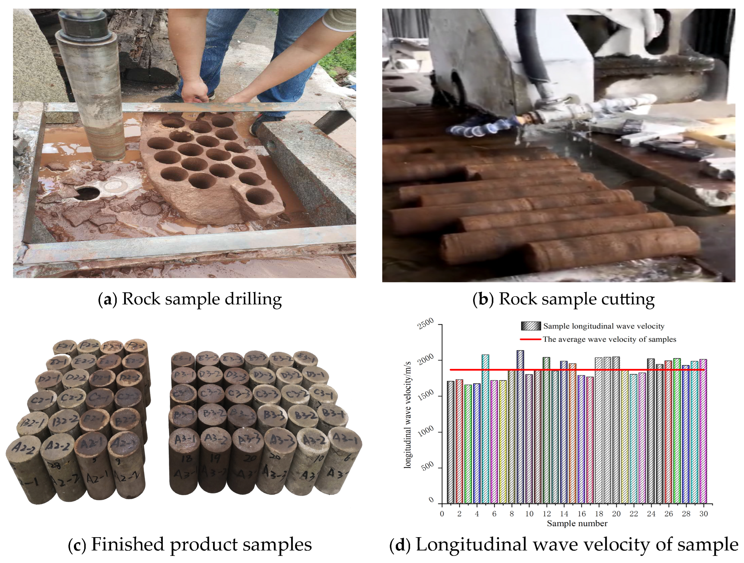
The sandstone samples exhibited a dark red color, and the rock products underwent analysis using a D/max-2500 X-ray diffractometer (Rigaku Corporation, Tokyo, Japan). This process identified the primary mineral compositions as quartz, plagioclase feldspar, potassium feldspar, calcite, and montmorillonite, with respective content percentages of 48.9%, 22.9%, 10.7%, 6%, and 6%. Adhering to the geological characteristics of the Xinzhuang coal mine ventilation shaft project and the on-site sampling protocols outlined in “Method for Sampling Coal and Rock Samples” (GB/T 19222) [47] and “Method for Determining the Mechanical Properties of Coal and Rock” (GB/T 23561.1-2009) [48], the samples were processed. In the laboratory, the rock samples underwent coring, cutting, and polishing to transform them into standard specimens measuring ϕ 50 mm × 100 mm, as shown in Figure 2. The processed standard rock samples were then subjected to acoustic wave testing to minimize errors from sample dispersion. The acoustic wave tests were conducted using a UTA-2000A ultrasonic testing analyzer (Hebei Jingwei Test Instrument Co., Ltd., Shijiazhuang, China), with 50 specimens tested. The longitudinal wave velocity of the specimens ranged from 1671 to 2038 m/s, with an average value of 1867 m/s and a dispersion coefficient of 1.978%. Rock specimens near the average longitudinal wave velocity were chosen for the creep test of saturated frozen sandstone.

2.3. Test Apparatus

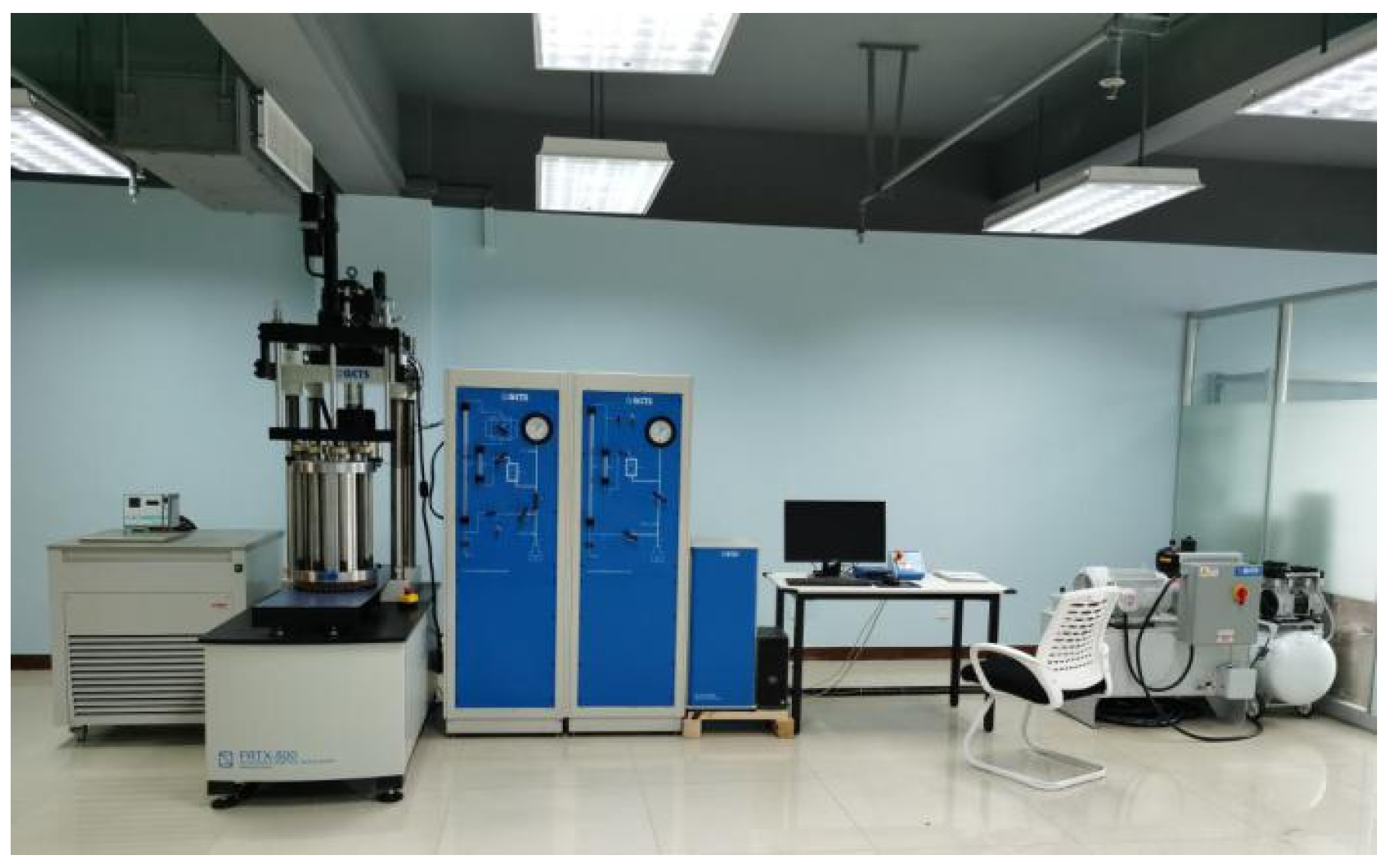
The test was conducted using the FRTX-500 rock triaxial (GCTS, Tempe, AZ, USA) and creep pressure testing machine at the National Key Laboratory of Green and Long-Life Road Engineering in Extreme Environment, as depicted in Figure 3. The temperature of the rock samples can be dynamically controlled and adjusted throughout the loading process, with a temperature control range spanning from −30 °C to 80 °C and an accuracy of ±0.01 °C. The maximum axial pressure that can be applied is 500 kN, while the maximum confining pressure and pore pressure are both 140 MPa, with an accuracy of 0.1%. The test equipment comprises five systems: the axial loading system, confining pressure loading system, high- and low-temperature control system, cold bath system, and data acquisition and processing system. These systems enable the triaxial creep testing of rock under varying temperature and pressure conditions and allow for the synchronous recording of axial and radial strains, as well as the creep curves of the rock during the loading process.

2.4. Pilot Program

Creep test specimens are dried in an oven at 105 °C for a minimum of 24 h. Subsequently, dry sandstone is vacuum-saturated in a vacuum saturator for a minimum of 12 h. Before loading the samples into the pressure chamber, the surface of the specimens is coated with Vaseline to reduce moisture migration during the process of specimen water evaporation and cooling, ensuring the reasonable accuracy of the test. The test temperature was set at −10 °C, in accordance with the common temperature of freezing well construction, with the room temperature condition serving as the comparison group. Based on the sampling depth in the field, four confining pressures of 0 MPa, 2 MPa, 4 MPa, and 6 MPa were established. The creep test was conducted following these steps: ① After loading the samples and injecting oil, the cryogenic system was adjusted to freeze the pressure chamber at a rate of 10 °C per hour. Once the test temperature was reached, the temperature was held constant for 8 h to ensure the uniform internal temperature of the rock samples. ② Under stress control mode, confining pressure was applied according to the condition σ1 = σ2 = σ3, and the system was stabilized for 2 min. ③ With the confining pressure maintained, loading was performed in steps of 20%, 30%, 40%, 50%, 60%, 70%, 80%, and 90% of the peak strength obtained from conventional tests, with each level of the loading set at 10% of the peak strength, as shown in Table 1. Each loading stage lasted 12 h, with a loading rate of 0.05 MPa per second, to eliminate the impact of the loading rate on the test results. The loading process continued until the frozen sandstone was destroyed, while the temperature of the rock sample bin was consistently maintained at the set temperature.

2.5. Creep Characterization Results

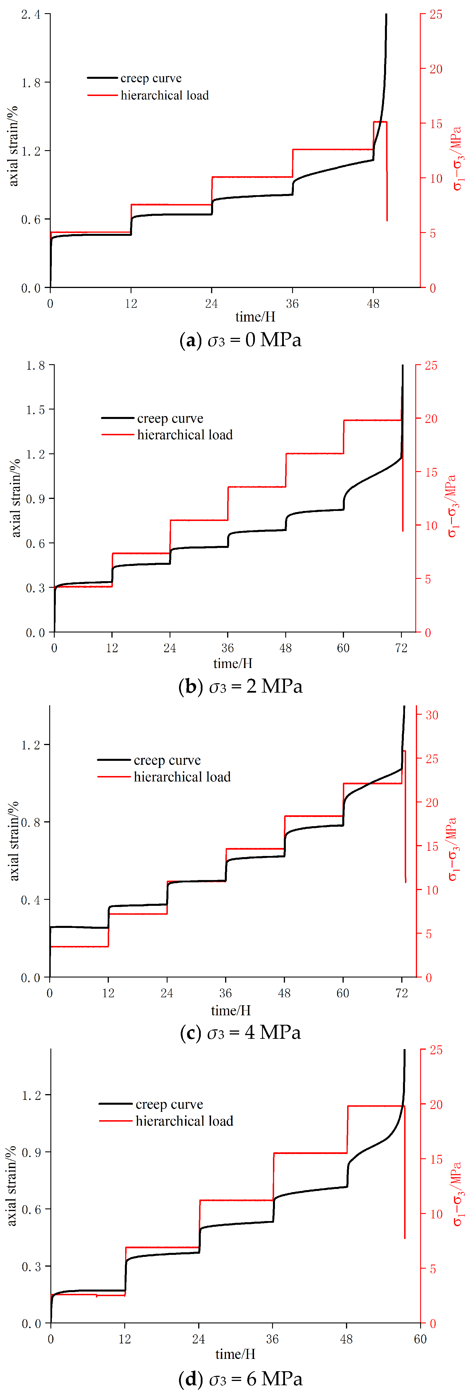
Creep is a physical characteristic of material deformation that accumulates over time under constant load. This phenomenon is mainly characterized by three stages of plastic deformation: the deceleration creep stage, steady-state creep stage and accelerated creep stage. The deceleration creep stage: the creep rate gradually decreases over time as the pores within the material close, and the strain rate slows down. The steady-state creep stage: the creep rate remains constant, with strain continuing to increase at a fixed speed, and this stage persists for an extended period. The accelerated creep stage: the creep rate increases rapidly until the material breaks. Based on the results of uniaxial and triaxial compression tests, the loading was divided into several stages, with the applied loads set at various percentages of the peak strength. The creep test curves for frozen sandstone under saturated conditions are presented in Figure 4.
Figure 4 illustrates that saturated frozen sandstone exhibits distinct creep characteristics under varying peripheral and axial pressures. The creep test curve possesses the following characteristics.
(1) After each loading phase, the frozen sandstone experiences significant transient deformation before gradually entering a creep steady state, during which the rock’s damage effect is considerably less than its hardening effect.
(2) Under conditions of low stress, frozen sandstone exhibits minimal creep characteristics, and the deformation during the creep steady-state phase is very slow. As the stress level increases, the creep deformation begins to accelerate rapidly, and the creep rate rises. When the stress approaches the yield point (the transition point from the elastic stage to the plastic stage of a material), the creep steady-state phase transitions into a nonlinear creep acceleration phase. At this juncture, the hardening effect of the frozen rock diminishes, and the damage effect intensifies, leading to cracking in the frozen sandstone. This marks the onset of significant damage, signaling that the rock is on the verge of destabilization.
(3) At a temperature of −10 °C in frozen sandstone, the total creep strain increases with rising confining pressure. Concurrently, the destructive stress (the stress that causes the material to fail) also increases, yet the creep loading time diminishes, exhibiting clear nonlinearity. The rock particles’ interconnectivity is bolstered by the confining pressure, enhancing the material’s plasticity. This, in turn, correspondingly elevates the bearing capacity and the long-term strength of the saturated frozen rock.

3. Damage Characteristics and Creep Evolution of Frozen Sandstone

3.1. Damage Characterization Based on Acoustic Emission Energy Parameters
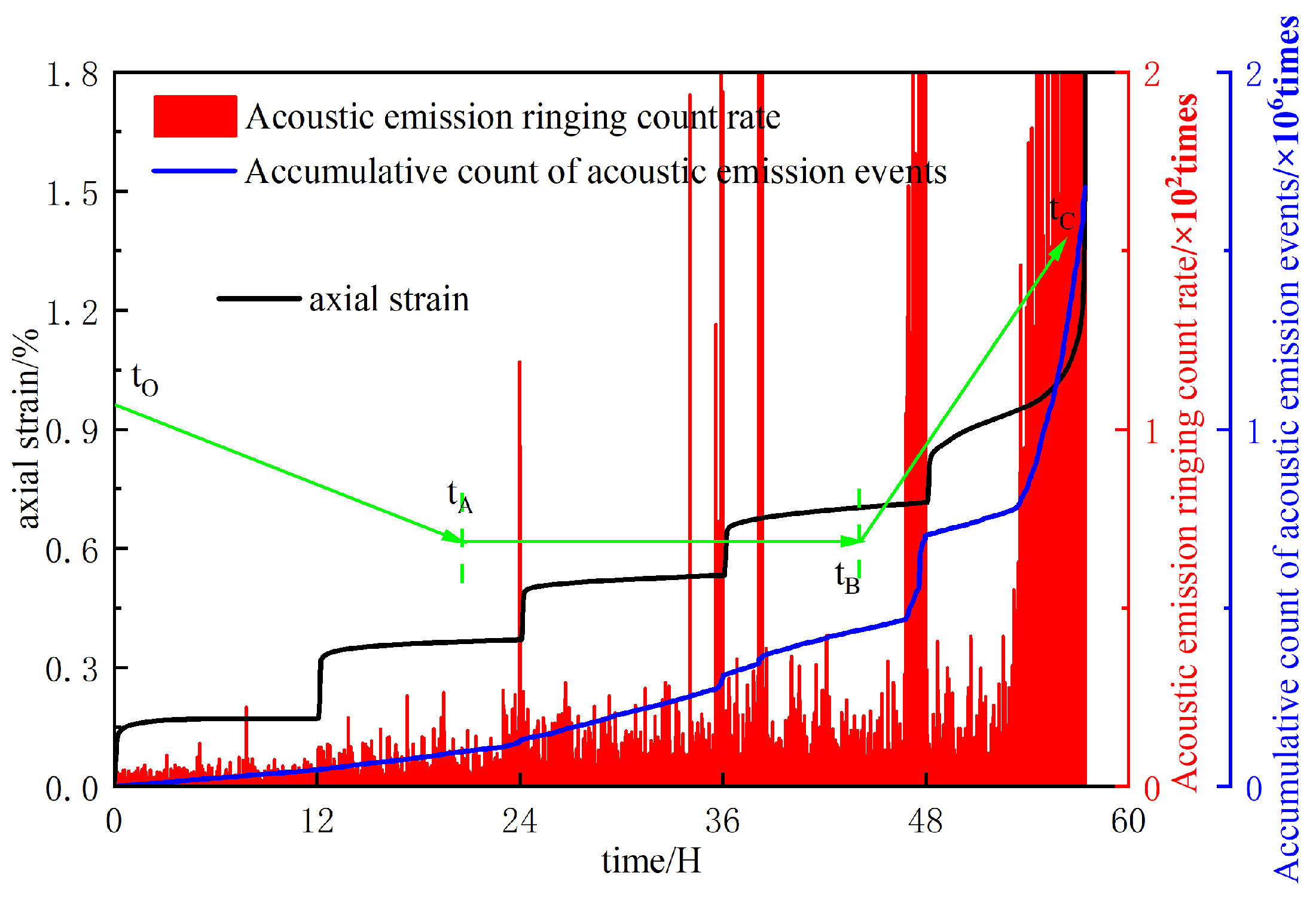
The first stage (deceleration creep): The signal primarily originates from the dislocation slip and interaction of material particles, initiating plastic deformation within, although macroscopic damage has not yet been significantly formed. A certain number of acoustic emission signals are present, but the overall strength remains very low. The second stage (steady-state creep): Micro-damage begins to form and grow slowly, which is one of the primary sources of acoustic emission. The acoustic emission activity at this stage reflects the early and stable accumulation process of damage. The acoustic emission events may remain relatively stable or change slowly, and the signal intensity is primarily medium or low. The third stage (accelerated creep): Micro-voids and microcracks accelerate their growth and connect with each other to form a larger crack network, causing local areas to fail and the effective bearing area to decrease rapidly. This results in a sharp increase in the strain rate, a significant rise in acoustic emission events, and a marked increase in signal intensity, particularly in the number and magnitude of high-energy events. As the breaking point approaches, explosive strong signals may appear. In this paper, acoustic emission experiments were conducted on saturated frozen sandstone under conditions of σ3 = 6 MPa and T = −10 °C. The results are presented in Figure 5.
The essence of creep deformation in geotechnical materials involves the gradual accumulation of damage to the load-bearing structure, typically resulting from the fracture of internal bonded particles and frictional slip between grains. Acoustic emission technology is employed to monitor damage during the creep deformation of saturated frozen sandstone specimens, as depicted in Figure 5. tO: initial point, tA: acoustic emission event occurrence point, tB: acoustic emission event surge point, and tC: acoustic emission event end point. The figure illustrates that at the onset of decay creep (t0tA), the specimen exhibits individual larger acoustic emission signals, which are generally flat at a certain level. During the stable creep stage (tAtB), the intensity of the acoustic emission signals is stronger compared to the attenuation stage, yet they mostly remain at a consistent level, with occasional larger acoustic emission signals. As the stable creep transitions to accelerated creep (tBtC), the intensity of the acoustic emission signals increases, still maintaining a consistent level, but with a few larger acoustic emission signals. Throughout the transition from stable creep to accelerated creep (tAtBtC), the acoustic emission signals intensify significantly, suggesting that the rock structure is beginning to experience accelerated damage. Consequently, the damage creep model for saturated frozen sandstone requires further development.
Kachanov [47] argued that the damage variable can be expressed as
D = A D A
where A represents the undamaged portion of the specimen section and AD denotes the damaged portion.
Using the acoustic emission signal to describe the aforementioned equation, let the cumulative acoustic emission counts, Ctol, represent the complete destruction of the nondestructive specimen section, A. Then, acoustic emission counts Cw per unit area correspond to microelement destruction:
C w = C t o l A
When the injury vicinity corresponding to the specimen part reaches AD, the cumulative acoustic emission count is CD:
C D = C w A D = C t o l A A D
Then, the damage variable, described based entirely on the cumulative acoustic emission power, can be expressed as
D = C D C t o l
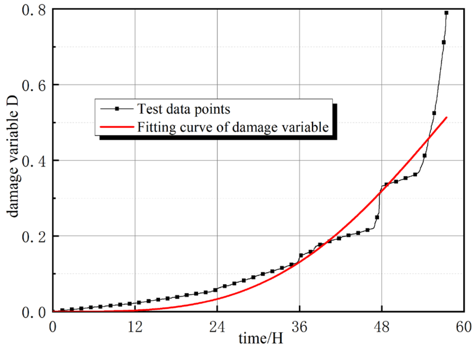
The damage evolution of the saturated frozen sandstone specimen, subjected to a confining pressure of 6 MPa and a freezing temperature of −10 °C, was analyzed using AE signals, as depicted in Figure 6 (corresponding to the creep behavior depicted in Figure 5). As can be seen from the figure, the damage variable shows a positive correlation with time. The curve exhibits an upward concave trend, suggesting that its derivative increases over time—that is, the rate at which damage accumulates accelerates as the test progresses. Furthermore, the maximum value of the damage variable consistently remains below 1 throughout the duration of the test, indicating incomplete failure within the observed timeframe. Based on the cumulative acoustic emission energy recorded during the experiment, the damage variable, D, is defined as follows:
D = C w C t o l = 1 exp ( α t β )
A comparison of Equation (5) with the damage variables derived from acoustic emission data is presented in Figure 6. As is evident from the figure, Equation (5) effectively describes the damage evolution during the creep of saturated frozen sandstone. In the equation, α = 5 × 10⁻⁷, β = 3.5, and correlation coefficient R2 = 0.95.
Figure 6. Comparison of theoretical damage variables with acoustic emission damage variables.
Water 17 02492 g006
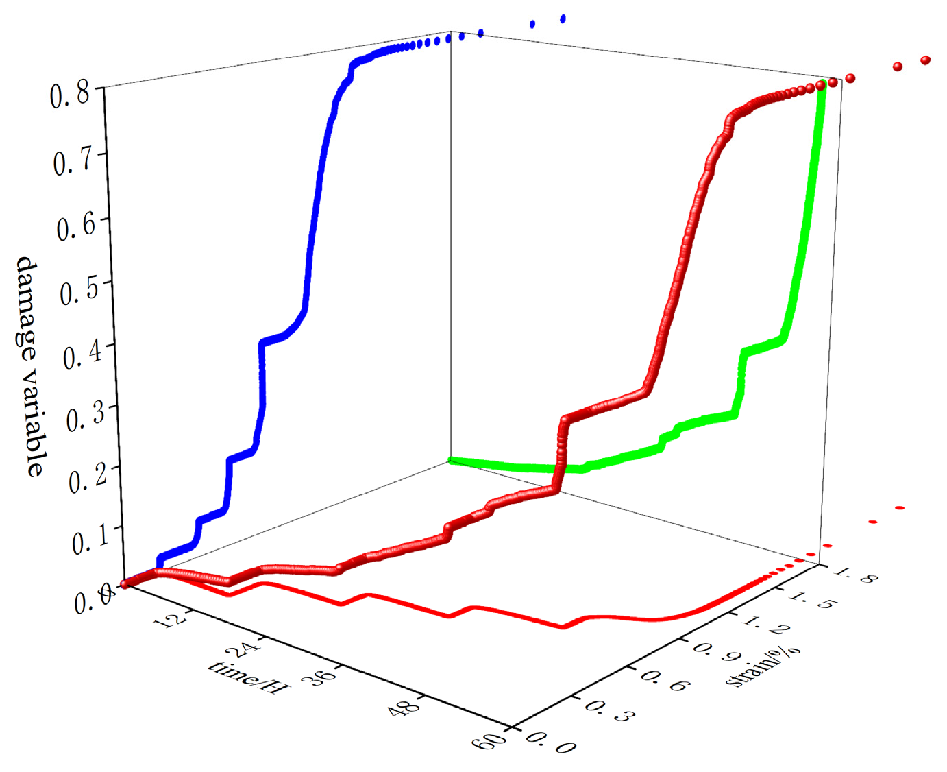
The rule governing the change in damage variables of frozen sandstone can be determined using the measured data. Figure 7 illustrates the three-dimensional variation in damage variable D over time and strain in frozen sandstone at −10 °C and under a confining pressure of 6 MPa. The diagram reveals that the blue curve exhibits slow changes initially, which corresponds to the decay creep stage. During this phase, internal natural microcracks gradually close due to external forces, and the damage variable experiences a slight increase. The green curve suggests that upon entering the steady deformation stage, the continuous application of axial stress facilitates the gradual formation of new microcracks and an increased rate of damage variable growth. The red curve represents the accelerated creep stage, where the damage variable rises sharply, cracks expand and propagate rapidly, and the damage ultimately reaches its peak, Dmax, signaling the onset of creep failure. The distinct color curves distinctly reflect the evolution trend of damage variables across each creep stage and validate the rationality of the damage evolution law.

3.2. Damage Evolution During Creep

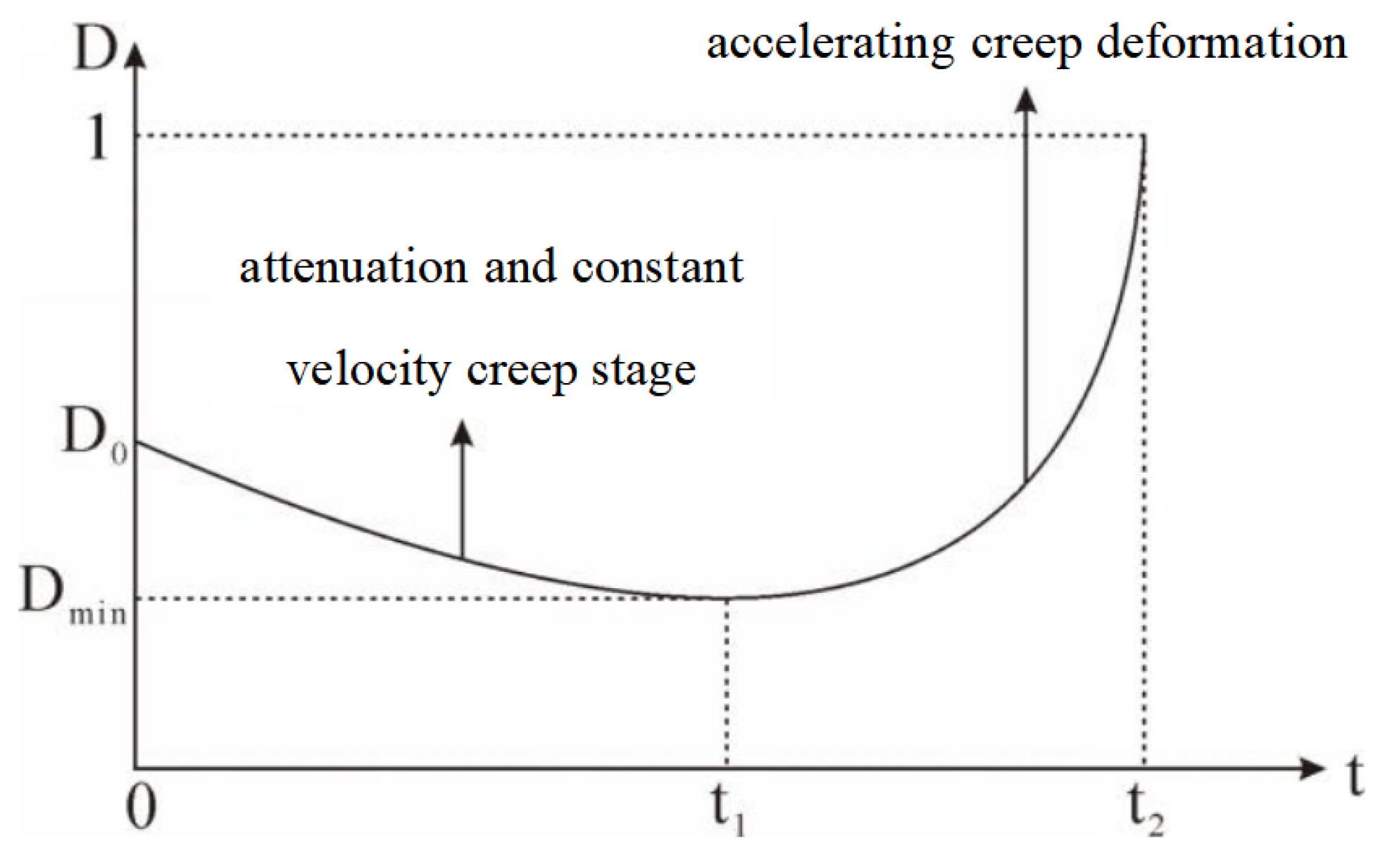
Ideally, the trend of the damage variable over creep time is depicted in Figure 8.
Points t1 and t2 in Figure 8 represent the onset of rock creep into the accelerated stage and the end of final creep damage, respectively. The nonlinear characteristics of rocks during the creep process render the linearization of traditional combined models ineffective in accurately describing the phenomenon. By incorporating a damage variable into the creep process of rocks, the entire creep process can be effectively described, a fact that has been confirmed in the existing literature. The concept of the damage variable was initially introduced in the field of injury mechanics, with the more commonly used being the damage variable evolution equation proposed by Kachanov [49]:
d D d t = C σ 1 D n
where σ represents the stress; D is the damage variable; t is the time; and C and n are the damage variable curve values of different material parameters.
By integrating Equation (6), we have
1 D 1 + n 1 + n + A = C σ n t
Place A is the integration constant. By substituting the boundary conditions, when t = 0, D = D(0), which is obtained through the aid of substituting Equation (7):
1 D 0 1 + n 1 + n 1 D 1 + n 1 + n = C σ n t
When t = t1, at this point, the pores and cracks in the rock are compacted, and the damage variable reaches its minimal value; that is, D = D(min). This value is then substituted into Equation (8):
1 D 0 1 + n 1 + n 1 D min 1 + n 1 + n = C σ n t 1
Therefore, it is possible to determine the time required for rocks to undergo creep from the onset of damage until the damage variable reaches its minimum value:
t 1 = 1 D 0 1 + n 1 D min 1 + n 1 + n C σ n
When t = t2, at this point, the enlargement of pores and cracks in the rock reaches its maximum, and the damage variable attains its highest value, that is, D = D(max) = 1, which is substituted into Equation (8):
1 D 0 1 + n 1 + n = C σ n t 2
Therefore, it is possible to determine the time elapsed from the onset of damage to the peak value of the damage variable for rock creep.
t 2 = 1 D 0 1 + n 1 + n C σ n
According to Equation (10), when the initial value of the damage variable takes its minimum value, the smaller the external load during the creep process, the longer the duration of the decay creep stage and the steady deformation stage; on the contrary, when the external load is greater, the duration of these stages is shorter. When the initial value of the damage variable is larger, this indicates a greater number of internal defects in the rock, and a longer time will be required after applying the same external load to reach the same minimum value of the damage variable. When the minimum value of the damage variable is higher, this indicates that under the condition where the external load is equal to the initial value of the damage variable, the repair of the rock damage will take less time. Substituting Equation (10) into Equation (8), the damage variable evolution equations for the two stages of decay creep and steady deformation creep at t < t (1) are calculated:
D 1 = 1 t 1 t t 1 1 D 0 1 + n + t t 1 1 D min 1 + n 1 1 + n
Substituting Equation (12) into Equation (8), the evolution equation for the damage variables in the accelerated creep phase at tt (1) is obtained:
D 2 = 1 1 D 0 t 2 t t 2 1 1 + n
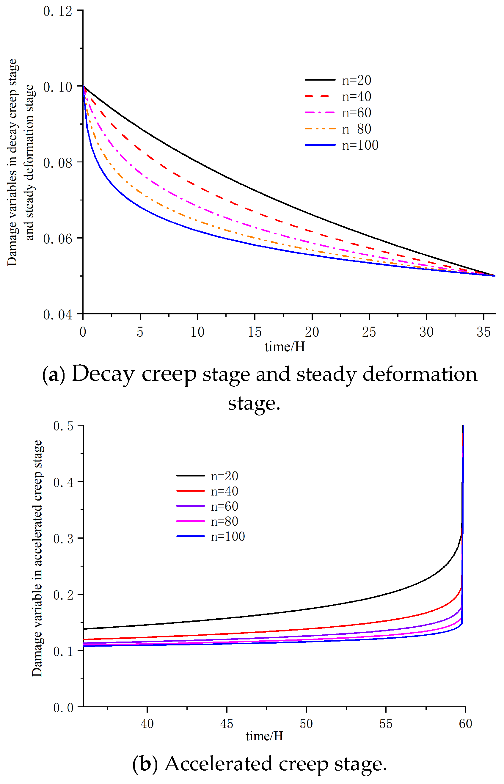
In this paper, t1 = 36 h and t2 = 58 h are selected as the example time points. Here, t1 signifies the starting time at which the rock creep curve enters the accelerated creep stage, while t2 denotes the time point when the creep process reaches final failure, completing the damage evolution. The initial damage value D0 = 0.1 reflects the initial defect level of the sample at the onset of loading. Conversely, the minimum damage value Dmin = 0.05 is a parameter that more accurately captures the early damage evolution characteristics of the material during the fitting process. Utilizing Equations (13) and (14), the curve of the damage variable over time can be derived, where n represents the value of the damage variable curve for different material parameters. These parameters are derived from the analysis of multiple sets of test data and are representative, and they exhibit a consistent trend across different tests, aligning with the curve fitting results depicted in Figure 9.
Figure 9 depicts the evolution of damage variable D for extreme values of the damage evolution exponent, n. The results show that throughout the attenuation and steady-state creep phases, larger values of n correspond to faster damage restoration within the same time interval. Conversely, during the accelerated creep phase, smaller values of n result in a more rapid accumulation of damage over time. These observations suggest that as the stress level increases, the rock material undergoes more severe damage, especially upon entering the accelerated creep phase, where the propagation and interconnection of microcracks significantly intensify the damage process.
During the creep decay stage, the creep curve exhibits nonlinear characteristics, with the creep rate gradually decreasing and hardening occurring in saturated frozen sandstone. At this juncture, the initial pores and cracks in the saturated frozen sandstone are progressively closing, and no new cracks are forming. Consequently, the damage behavior is repaired within this stage, and the damage variable is reduced from its initial value to a smaller one. As creep transitions into the steady-state creep stage, the creep curve develops linearly. One scenario presents a straight line with a tangent slope that is consistent with zero, indicating a steady creep rate during this stage. When creep enters the accelerated creep stage, the nonlinear characteristics significantly increase over time. The onset of rock softening begins to manifest as creep, and the creep rate rapidly accelerates. Creep deformation also becomes increasingly pronounced, ultimately resulting in cracks that lead to rock failure.

4. Fractional-Order Creep Ontological Model for Saturated Frozen Sandstone Considering Damage

In the previous chapter, the damage factor was established using acoustic emission events, and the damage evolution equation was formulated. In this chapter, the creep damage constitutive model is constructed, the creep parameters are inverted, and the influence of various factors on the creep damage constitutive model is explored.

4.1. Fractional Viscous Body

Hooke’s law suggests that the intrinsic relationship for an ideal elastic solid is σ (t)~d0ε (t)/dt0, Newton’s law shows that the intrinsic relationship for an ideal viscous fluid is σ (t)~d1ε (t)/dt1, and the intrinsic equation for an ideal viscoelastic fluid is between a perfect elastic solid and a perfect viscous fluid, with the intrinsic relationship being σ (t)~dβε (t)/dtβ (0 < β < 1). Regarding β, the cost of the transition from 0 to 1 describes the transformation of the material from elasticity to viscosity: when β = 0, the material behaves as a perfect solid; when β = 1, the material behaves as an ideal fluid; and when 0 < β < 1, the material exhibits characteristics between an ideal fluid and ideal solid, and this state is recognized as a fractional viscous body.
The eigenstructure relations for fractional-order viscous elements are
σ ( t ) = E η β d β ε ( t ) d t β , ( 0 β 1 )
where η is the viscosity coefficient; Eη is the fractional-order viscosity coefficient with physical dimension [MPa·tβ]; and β is the fractional-order derivative of the fractional-order viscosity body.
The creep response of saturated frozen sandstone under sustained loading conditions can be precisely characterized using a fractional viscoelastic element, as expressed in Equation (17). This formulation is derived through the rigorous application of Riemann–Liouville fractional calculus operators, maintaining dimensional consistency and the essential hereditary properties of geomaterials.
σ ( t ) = E η β D β ε ( t )
When σ(t) = σ0, the Laplace inverse transformation of the equation yields the creep equation for a fractional-order viscous body as
ε ( t ) = σ 0 E η β t β Γ ( 1 + β ) , ( 0 β 1 )
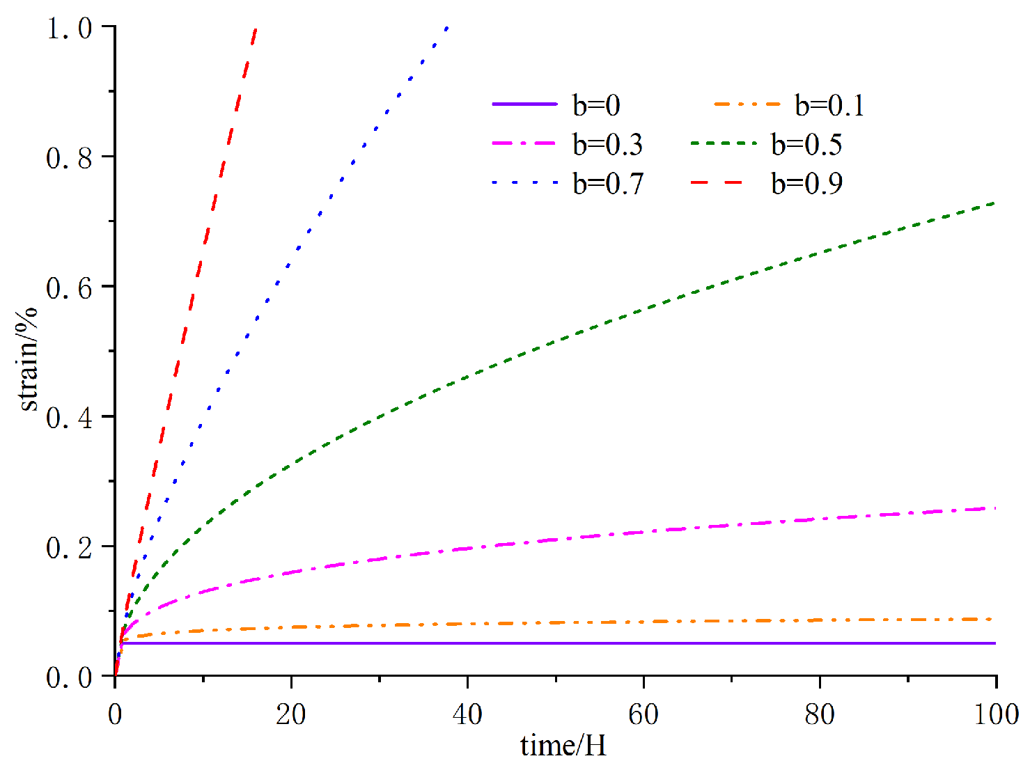
Using the parameter values σ = 10 MPa, E = 20 GPa, and η = 0.6 MPa, the creep curves for fractional-order viscosities with varying β values are derived from Equation (18) under constant stress, as depicted in Figure 10.
By varying parameter β, the fractional-order viscous model can effectively simulate the creep behavior of a material, capturing its transition between perfectly solid and perfectly fluid states. This also demonstrates that the fractional-order viscous body represents a synthesis of unknown elastic and viscous components. Parameters and β, incorporated into the model, play fundamental roles in controlling stress development and regulating the creep rate, making the fractional-order viscous body an ideal candidate for precisely representing nonlinear creep behavior.
As shown in Figure 10, when the creep stress remains constant, the fractional-order viscous body, as previously suggested, exhibits nonlinear creep characteristics. Notably, as the value of β increases, the creep characteristics become more pronounced. For lower values of β, the change in creep is minimal, whereas for higher values, the change in creep becomes significantly larger. These results highlight that β governs the order of the fractional derivative, and adjusting its value allows for an accurate description of the nonlinear asymptotic creep process.

4.2. Fractional Creep Constitutive Model Considering Damage

Based on the analysis of damage behavior during the creep process, a fractional-order nonlinear creep model that incorporates low-temperature damage–stress coupling has been developed. This model integrates fractional-order viscoelastic elements with a series of mechanical components, forming a system that includes five mechanical elements and three distinct mechanical models: elastomers, fractional-order viscoelastomers, and fractional-order viscoplastomers. The constitutive equations derived from this model effectively capture the three stages of creep, as depicted in Figure 11.
In the figure, E1 and E2 represent the modulus of elasticity, 1ζ and 2ζ represent the coefficient of viscosity, σs represents the yield strength of sandstone, D is the damage value, ζ is the fractional derivative order of a fractional-order viscous body, and γ is the fractional derivative order of a fractional-order viscoplastic body.
① When σ < σs, two parts of the model are involved in the creep deformation of saturated frozen sandstone, as seen in the following equation:
σ 1 = E 1 ( 1 D ) ε 1 σ 2 = E 2 ( 1 D ) ε 2 + E η 1 ζ ( 1 D ) D ζ ε ( t ) σ = σ 1 = σ 2 ε = ε 1 + ε 2
② When σσs, three parts of the model are involved in the creep deformation of saturated frozen sandstone, as seen in the following equation:
σ 1 = E 1 ( 1 D ) ε 1 σ 2 = E 2 ( 1 D ) ε 2 + E η 1 ζ ( 1 D ) D ζ ε ( t ) σ 3 = σ s + E η 2 γ ( 1 D ) D γ ε ( t ) σ = σ 1 = σ 2 = σ 3 ε = ε 1 + ε 2 + ε 3
In summary, the expression below is derived by applying the Laplace transform to the equation above: the fractional-order nonlinear creep eigenstructure equation for saturated sandstone is as follows:
ε ( t ) = σ 0 E 1 ( 1 D ) + σ 0 E η 1 ζ ( 1 D ) t ζ E ζ , ζ + 1 ( E 2 E η 1 ζ t ζ ) , σ < σ s σ 0 E 1 ( 1 D ) + σ 0 E η 1 ζ ( 1 D ) t ζ E ζ , ζ + 1 ( E 2 E η 1 ζ t ζ ) + σ 0 σ s E η 2 γ ( 1 D ) t γ Γ ( 1 + γ ) , σ σ s
A fractional-order viscous element is a fundamental component that represents a state of matter intermediate between an ideal solid and a Newtonian fluid. This concept extends the integer-order derivative to a fractional-order derivative, capturing the gradual rather than abrupt changes in material properties during the creep process. The fractional-order derivative, which ranges from zero to one, better describes the asymptotic nature of material behavior during creep. This unique property closely aligns with the mechanical characteristics of viscoelastic bodies, quantifying their behavior with specific values.
Upon analyzing the damage variables throughout the entire creep process, a damage constitutive equation has been established to describe the creep behavior of saturated frozen sandstone. The reasons why damage behavior can be disregarded during the creep decay and steady deformation stage need to be explored. Conversely, the damage variables are crucial to consider during the creep acceleration stage. The developed stage creep constitutive equation effectively captures the qualitative expression of the three phases of creep. Thus, the creep constitutive relationship for saturated frozen sandstone is depicted below.
(1) During the creep decay and steady-state phases, the creep damage equation is attributed to negligible damage behavior:
ε ( t ) = σ 0 E 1 + σ 0 E 2 ( 1 exp ( E 2 η 2 t ) ) σ < σ s
(2) During the creep acceleration stage, the extent of damage conducted increases dramatically. Therefore, the creep damage equation is
ε ( t ) = σ 0 E 1 + σ 0 E 2 ( 1 exp ( E 2 η 2 t ) ) + σ 0 σ s η 0 ( 1 D ) t n σ σ s

4.3. Fractional-Order Model Parameter Inversion

Parameter inversion is an essential component following the establishment of the intrinsic model, and the least squares method is utilized to solve nonlinear regression. During the creep parameter inversion process, the methodology for the fractional-order model is identical to that of the viscoelastic–plastic model. The parameter inversion effects of the fractional-order model for sandstone under varying temperatures and pressures are depicted in Figure 12, with the corresponding parameter values presented in Table 2.
The parameter inversion results indicate that E1 initially increases and then decreases. In contrast, E2 decreases over time until it stabilizes at a certain value. 1 shows an increasing trend as the loading coefficient rises. 2, however, only becomes significant when the creep load exceeds the long-term strength, primarily influenced by the viscous–plastic effects that dominate during the latter half of the creep process. With the growth of time, fractional-order derivative ζ continues to increase and finally approaches 1. The order change rules of γ and ζ are basically the same, with the difference being that fractional-order derivative ζ runs through the entire process of creep, while fractional-order derivative γ only appears after the creep stress is larger than the long-term strength. In summary, the fractional-order creep damage model proposed in this section is not only very consistent with the experimental results, but the fractional order of each derivative of the order of change can also reflect the evolutionary behavior of the material throughout the entire creep process. The clear meaning of the fractional order of the derivative of the order change can be used as a reference for a follow-up study of the saturated freezing sandstone creep from a microscopic perspective.

5. Fractional-Order Model Creep Parameter Impact Level Analysis

Referring to the fitting analysis of the fractional-order model and the inversion results of the creep parameters in Table 1, the sensitivity of the creep parameters under the working conditions of −10 °C, 6 MPa confining pressure, and a loading coefficient of 0.5 is analyzed. This serves as an example of the results of the creep behavior of saturated frozen sandstone. By substituting parameters E1 = 0.0403, 1 = 0.8563, ζ = 0.0253, E2 = 1.0756, D = 0.5702, 2 = 0.1675, and γ = 0.5380 into the fractional-order model eigenequations, the extent to which the tuning of specific parameters affects the creep properties is reflected in the analysis.

5.1. Effect of Stress Level

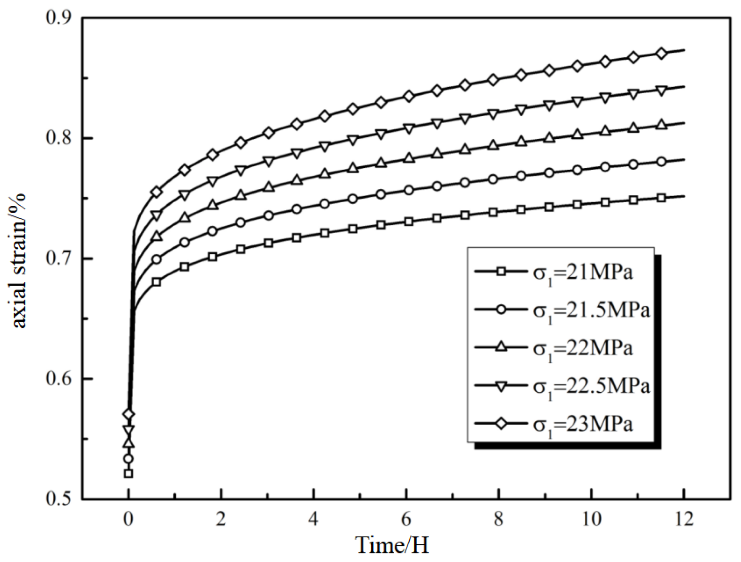
When the remaining parameters are held constant and only the stress level is varied, such that σ = 21 MPa, 21.5 MPa, 22 MPa, 22.5 MPa, and 23 MPa, the creep curves at these different stress levels can be obtained, as illustrated in Figure 13.
Based on the creep test analysis presented in Figure 13, the experimental results demonstrate stress-dependent dual-phase creep behavior. As the applied stress increases, a corresponding incremental strain response is observed. Notably, when the applied stress is below the long-term strength threshold, higher stress magnitudes correlate with extended durations in the stable creep phase. Conversely, when the applied stress exceeds the long-term strength limit, increased stress levels result in shortened stable creep durations and more rapid transitions to accelerated creep regimes.

5.2. Effect of Fractional-Order Derivative ζ

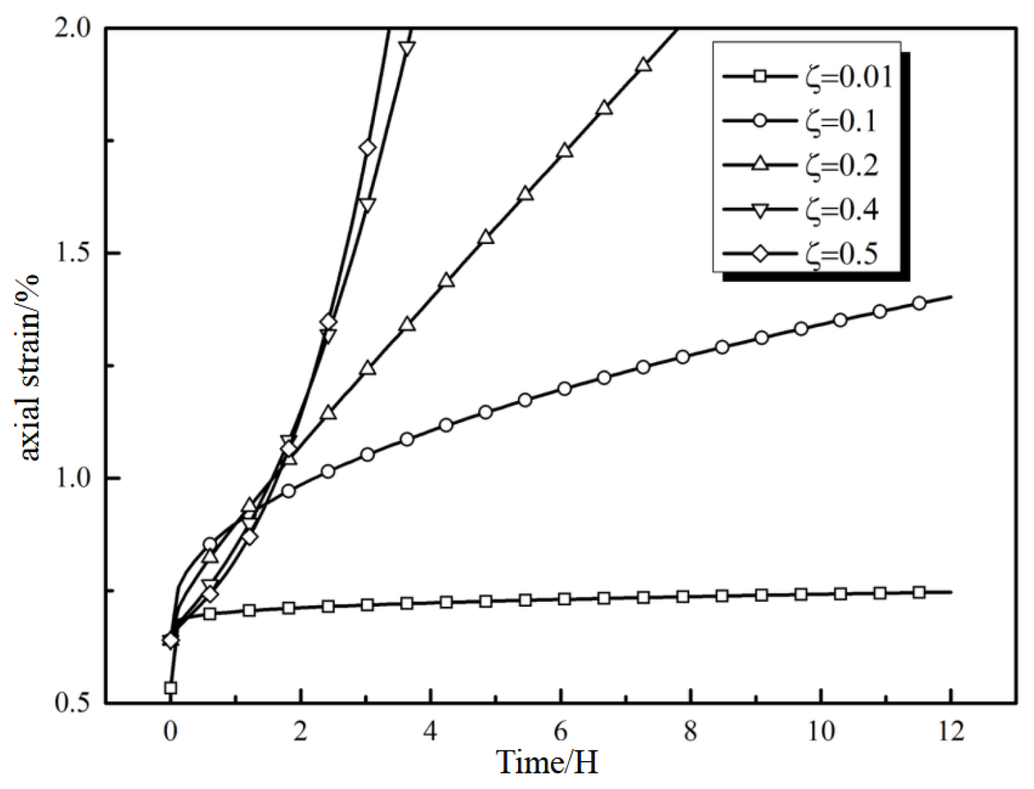
By keeping all other parameters constant and varying fractional-order derivative ζ to values of 0.01, 0.1, 0.2, 0.4, and 0.5, a series of creep curves corresponding to different ζ values were obtained, as shown in Figure 14.
Figure 14 illustrates that as the order of fractional-order derivative ζ increases, creep deformation tends to increase. When ζ is less than 0.1, the creep process enters the plateau stage after a relatively short period, with minimal deformation. In contrast, when ζ exceeds 0.1, creep deformation experiences a substantial increase after a short time, leading to the accelerated creep stage.
These results indicate that a higher value of ζ corresponds to a shorter duration of the creep steady deformation stage. Furthermore, the value of ζ can influence the time at which the creep enters the accelerated stage. Additionally, it is demonstrated that fractional-order viscosity can characterize creep expansion during the accelerated creep stage of saturated frozen sandstone, and there exists an inflection point in this process.

5.3. Effect of Fractional-Order Derivative γ

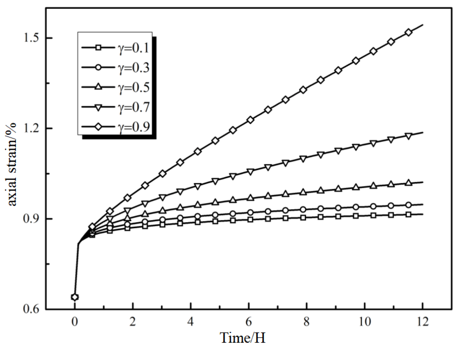
When keeping the parameters’ relaxation unchanged, by solely modifying the order of the fractional-order by-product γ to γ = 0.1, 0.3, 0.5, 0.7, 0.9, a set of creep curves with distinctive γ values can be obtained, as demonstrated in Figure 15.
Figure 15 indicates that the fractional-order viscoplastic model can faithfully replicate the nonlinear creep acceleration process of rocks. As the order of fractional derivative γ increases, the amount of creep in the sandstone material also increases, and the corresponding creep rate becomes faster. The steady deformation stage can only be maintained for a very brief period of time, and the creep acceleration phase occurs over a shorter duration, during which creep damage can be triggered.

5.4. Impact of Damage Variable

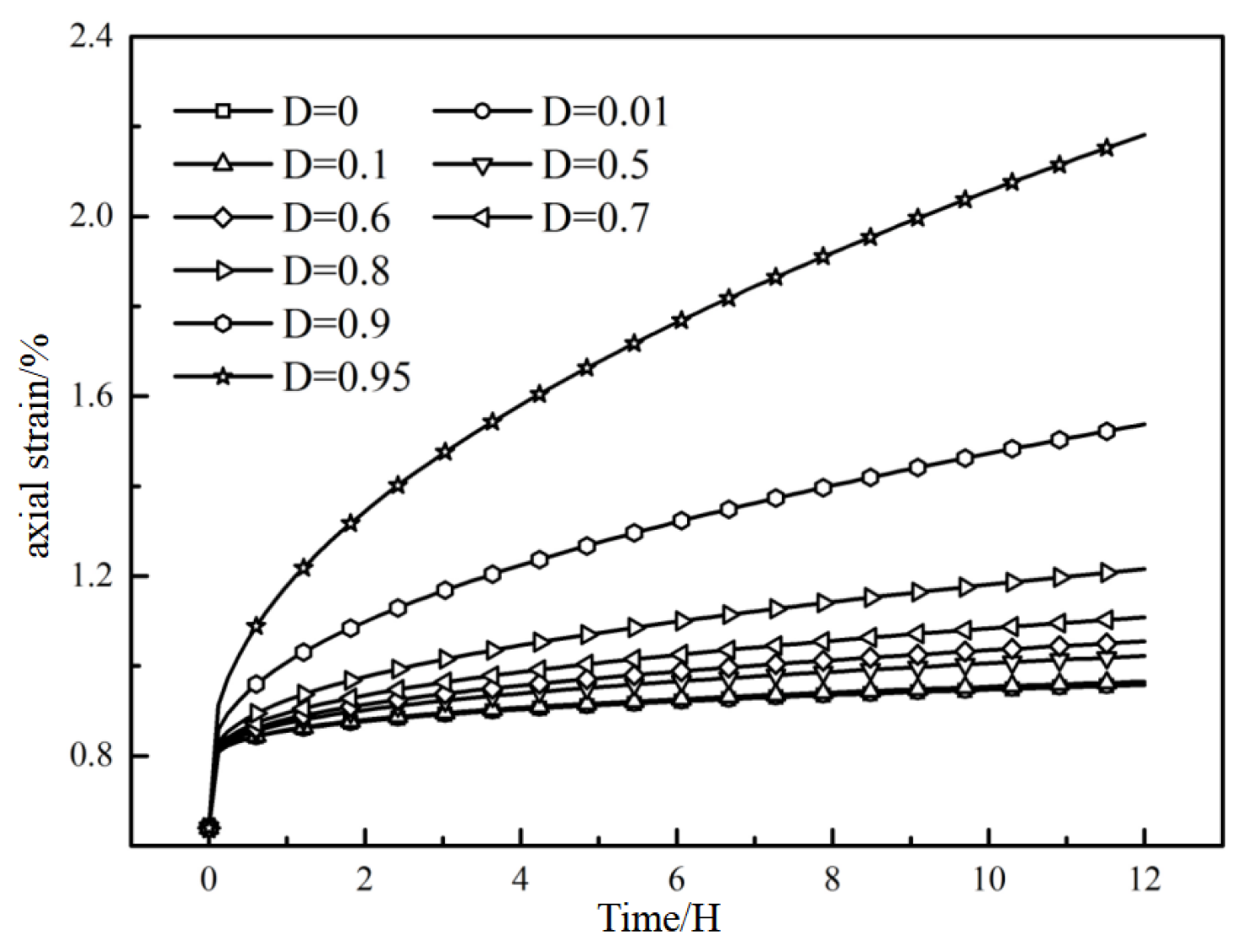
When all other parameters remain constant and only the damage variables are altered, for instance, by setting D to 0, 0.01, 0.1, 0.5, 0.6, 0.7, 0.8, 0.9, and 0.95, a series of creep curves corresponding to these different damage variables can be obtained, as illustrated in Figure 16.
Based on the figure’s evaluation, when the damage variable is zero, there is no unsteady creep behavior in the creep stage of saturated frozen sandstone. When the damage variable is greater than zero, unsteady creep behavior occurs. As the value of damage variable D increases, the greater the pressure and the quicker it is to enter the accelerated creep stage. This indicates that the damage effect significantly accelerates the creep fracture of the rock at this stage. It can be observed in Figure 16 that when damage variable D is between 0 and 0.5, the creep constant-state stage can last for a long time, and the pressure increase is very small. When damage variable D is between 0.5 and 0.8, the creep steady-state rate increases, and the pressure gradually increases, but the rock does not fail. When damage variable D is between 0.8 and 1, the stress increase is very large, and the saturated frozen sandstone fails in a very short period of time. This result is consistent with the damage behavior analysis, and in the decay and steady-state phases, it is considered that the damage effect is small, and it is practical to define the damage variable within this phase as zero.
The creep behavior of saturated frozen sandstone is governed by four principal parameters: the stress level, fractional-order derivatives ζ and γ, and the damage variable. The stress level predominantly controls the duration of the steady-state creep phase and the transition timing to the accelerated creep stage. Fractional-order derivatives ζ and γ collectively determine the characteristic creep curve morphology and the strain rate evolution across distinct creep phases. The damage variable dictates the evolution of creep-induced damage, quantified numerically through its magnitude. Notably, this parameter influences the creep curve morphology only when exceeding zero, as damage effects manifest exclusively under positive values. Furthermore, the damage variable regulates both the damage accumulation rate and magnitude during the entire creep process. Higher damage variable values correlate with intensified damage kinetics, characterized by the rapid attainment of peak damage and amplified creep deformation magnitudes.

6. Conclusions

(1) The essence of creep deformation in saturated frozen sandstone involves the progressive accumulation of internal crack evolution and structural damage. Acoustic emission signals are employed to characterize the damage variables of saturated frozen sandstone bodies, and the relationship equation between damage variables and time, D = 1 − exp (−αtβ), is established to analyze the damage evolution law at each stage of creep.
(2) A fractional calculus framework has been incorporated to develop a viscoelastic constitutive model that integrates fractional-order viscosity and damage evolution mechanisms. This theoretical framework allows for a systematic examination of inverse parameter variations within the fractional creep model, revealing their physical interpretations and evolutionary patterns. The fractional-order parameters exhibit intrinsic connections with microstructural evolution throughout the creep process, offering critical insights for the multiscale analysis of saturated frozen sandstone behavior. Additionally, the model’s demonstrated validity in capturing accelerated creep phases and damage accumulation enhances its applicability in geotechnical engineering research, spanning from microscopic mechanisms to macroscopic deformations.
(3) The creep behavior of saturated frozen sandstone is governed by four major parameters: the stress level, fractional-order derivatives ζ and γ, and the damage variable. The stress level controls the length of the steady-state segment and the transition timing to the accelerated creep stage. Fractional-order derivatives ζ and γ modify the creep curve morphology and strain-rate evolution during the entire creep phase, while the damage variable dictates both the rate and magnitude of damage accumulation throughout this process.

Author Contributions

Investigation, Y.W. and H.P.; data curation, Y.W.; writing—original draft preparation, Y.W.; writing—review and editing, H.P. All authors have read and agreed to the published version of the manuscript.

Funding

This work was supported by the Shaanxi Province Youth Science and Technology Rising Star Project (2023KJXX-093), Shaanxi Natural Science Basic Research Youth Project (2024JC-YBQN-0355), General Projects of the National Natural Science Foundation of China (42271490), and China Communications Construction Applied Basic Research Project (2021-ZJKJ-PTJS02).

Data Availability Statement

The original contributions made in this study are included in the article. For further inquiries, please contact the corresponding author.

Conflicts of Interest

Author Yao Wei and Hui Peng were employed by the company CCCC First Highway Consultants Co., Ltd. The remaining authors declare that the research was conducted in the absence of any commercial or financial relationships that could be construed as a potential conflict of interest.

Correction Statement

This article has been republished with a minor correction to the Data Availability Statement. This change does not affect the scientific content of the article.

References

  1. Griggs, D. Creep of rocks. J. Geol. 1939, 47, 225–251. [Google Scholar] [CrossRef]
  2. Jun, S.; Wang, S.J. Rock mechanics and rock engineering in China: Developments and current state-of-the-art. Int. J. Rock Mech. Min. Sci. 2000, 37, 447–465. [Google Scholar]
  3. Zhang, H.M.; Yang, G.S. Damage Constitutive Model of Loaded Rock Under Freeze-thaw Condition. J. Wuhan Univ. Technol. 2013, 35, 79–82. [Google Scholar]
  4. Li, Z.Y.; Yang, G.S.; Wei, Y. Construction of frozen Sandstone creep damage model and analysis of influencing factors based on fractional-order theory. Arab. J. Sci. Eng. 2021, 46, 11373–11385. [Google Scholar] [CrossRef]
  5. Li, J.L.; Zhu, L.Y.; Zhou, K.P.; Chen, H.; Gao, L.; Lin, Y.; Shen, Y.-J. Non-linear creep damage model of sandstone under freeze-thaw cycle. J. Cent. South. Univ. 2021, 28, 954–967. [Google Scholar] [CrossRef]
  6. Chen, K.S. A damage treatment of creep failure in rock salt. Int. J. Damage Mech. 1997, 6, 122–152. [Google Scholar] [CrossRef]
  7. Bellenger, E.; Bussy, P. Phenomenological modeling and numerical simulation of different modes of creep damage evolution. Int. J. Solids Struct. 2001, 38, 577–604. [Google Scholar] [CrossRef]
  8. Kranz, R.L. Crack growth and development during creep of Barre granite. Int. J. Rock Mech. Min. Sci. Geomech. Abstr. 1979, 16, 23–35. [Google Scholar] [CrossRef]
  9. Atkinson, B.K.; Meredith, P.G. Theory of subcritical crack growth with applications to minerals and rocks. Int. J. Rock Mech. Min. Sci. Geomech. Abstr. 1988, 25, 111–166. [Google Scholar]
  10. Miura, K.; Okui, Y.; Horii, H. Micromechanics-based prediction of creep failure of hard rock for long-term safety of high-level radioactive waste disposal system. Mech. Mater. 2003, 35, 587–601. [Google Scholar] [CrossRef]
  11. Kemeny, J.M. A model for non-linear rock deformation under compression due to sub-critical crack growth. Int. J. Rock Mech. Min. Sci. Geomech. Abstr. 1991, 28, 459–467. [Google Scholar] [CrossRef]
  12. Duncan, E.; Lajtai, E.Z. The creep of potash salt rocks from Saskatchewan. Geotech. Geol. Eng. 1993, 11, 159–184. [Google Scholar] [CrossRef]
  13. Goodwin, A.K.; O’Neill, M.A.; Anderson, W.F. The use of X-ray computer tomography to investigate particulate interactions within opencast coal mine backfills. Eng. Geol. 2003, 70, 331–341. [Google Scholar] [CrossRef]
  14. Thomachot, C.; Jeannette, D. Evolution of the petrophysical properties of two types of Alsatian sandstone subjected to simulated freeze-thaw conditions. Geol. Soc. Lond. Spec. Publ. 2002, 205, 19–32. [Google Scholar] [CrossRef]
  15. Ito, H.; Sasajima, S. A ten year creep experiment on small rock specimens. Int. J. Rock Mech. Min. Sci. Geomech. Abstr. 1987, 24, 113–121. [Google Scholar] [CrossRef]
  16. Fabre, G.; Pellet, F. Creep and time-dependent damage in argillaceous rocks. Int. J. Rock Mech. Min. Sci. 2006, 43, 950–960. [Google Scholar] [CrossRef]
  17. Hashiba, K.; Fukui, K. Time-dependent behaviors of granite: Loading-rate dependence, creep, and relaxation. Rock Mech. Rock Eng. 2016, 49, 2569–2580. [Google Scholar] [CrossRef]
  18. Mishra, B.; Verma, P. Uniaxial and triaxial single and multistage creep tests on coal-measure shale rocks. Int. J. Coal Geol. 2015, 137, 55–65. [Google Scholar] [CrossRef]
  19. Mansouri, H.; Ajalloeian, R. Mechanical behavior of salt rock under uniaxial compression and creep tests. Int. J. Rock Mech. Min. Sci. 2018, 110, 19–27. [Google Scholar] [CrossRef]
  20. Wang, X.; Lian, B.; Feng, W. A Nonlinear Creep Damage Model Considering the Effect of Dry-Wet Cycles of Rocks on Reservoir Bank. Water 2020, 12, 2396. [Google Scholar] [CrossRef]
  21. Yi, S.; Zhang, Y.; Yi, H.; Li, X.; Wang, X.; Wang, Y.; Chu, T. Study on the Instability Activation Mechanism and Deformation Law of Surrounding Rock Affected by Water Immersion in Goafs. Water 2022, 14, 3250. [Google Scholar] [CrossRef]
  22. Brzesowsky, R.H.; Hangx, S.J.; Brantut, N.; Spiers, C.J. Compaction creep of sands due to time-dependent grain failure: Effects of chemical environment, applied stress, and grain size. J. Geophys. Res. Solid. Earth 2014, 119, 7521–7541. [Google Scholar] [CrossRef]
  23. Nomikos, P.; Rahmannejad, R.; Sofianos, A. Supported axisymmetric tunnels within linear viscoelastic Burgers rocks. Rock Mech. Rock Eng. 2011, 44, 553–564. [Google Scholar] [CrossRef]
  24. Zhang, S.; Yun, X.; Song, Y.; Liu, W.; Yang, L. Fluid-Structure Coupling Creep Characteristics of Red-Bed Soft Rock in South China. Water 2022, 14, 4088. [Google Scholar] [CrossRef]
  25. Zhu, G.; Wang, S.; Zhang, W.; Li, B. Research on the Mechanism and Evolution Law of Delayed Water Inrush Caused by Fault Activation with Mining. Water 2023, 15, 4209. [Google Scholar] [CrossRef]
  26. Okubo, S.; Fukui, K.; Hashiba, K. Development of a transparent triaxial cell and observation of rock deformation in compression and creep tests. Int. J. Rock Mech. Min. Sci. 2008, 45, 351–361. [Google Scholar] [CrossRef]
  27. Maranini, E.; Brignoli, M. Creep behaviour of a weak rock: Experimental characterization. Int. J. Rock Mech. Min. Sci. 1999, 36, 127–138. [Google Scholar] [CrossRef]
  28. Heap, M.; Baud, P.; Meredith, P.; Vinciguerra, S.; Bell, A.F.; Main, I.G. Brittle creep in basalt and its application to time dependent volcano deformation. Earth Planet. Sci. Lett. 2011, 307, 71–82. [Google Scholar] [CrossRef]
  29. Kranz, R.L.; Scholz, C.H. Critical dilatant volume of rocks at the onset of Tertiary creep. J. Geophys. Res. 1977, 82, 4893–4898. [Google Scholar] [CrossRef]
  30. Lockner, D.A.; Byerlee, J.D. Changes in complex resistivity during creep in granite. Pure Appl. Geophys. 1986, 124, 659–676. [Google Scholar] [CrossRef]
  31. Tsai, L.S.; Hsieh, Y.M.; Weng, M.C.; Huang, T.H.; Jeng, F.-S. Time-dependent deformation behaviors of weak sandstones. Int. J. Rock Mech. Min. Sci. 2008, 45, 144–154. [Google Scholar] [CrossRef]
  32. Heap, M.J.; Baud, P.; Meredith, P.G.; Bell, A.F.; Main, I.G. Time-dependent brittle creep in Darley Dale sandstone. J. Geophys. Res. 2009, 114, B07203. [Google Scholar] [CrossRef]
  33. Zhang, H.M.; Wang, F.Y.; Yang, G.S. Experimental study on creep characteristics of infiltrated coal-rock under load. Arch. Appl. Mech. 2023, 93, 1331–1349. [Google Scholar] [CrossRef]
  34. Shan, R.L.; Bai, Y.; Ju, Y.; Han, T.-Y.; Dou, H.-Y.; Li, Z.-L. Study on the Triaxial Unloading Creep Mechanical Properties and Damage Constitutive Model of Red Sandstone Containing a Single Ice-Filled Flaw. Rock. Mech. Rock. Eng. 2021, 54, 833–855. [Google Scholar] [CrossRef]
  35. Yang, X.; Jiang, A.; Guo, X. Effects of water content and temperature on creep properties of frozen red sandstone: An experimental study. Bull. Eng. Geol. Environ. 2021, 81, 51. [Google Scholar] [CrossRef]
  36. Li, S.; Tao, W.; Zhang, F.; Yao, X. Experimental study of the dynamic characteristics of sandstone with preexisting creep damage. Mech. Time-Depend. Mater. 2021, 26, 955–973. [Google Scholar] [CrossRef]
  37. Wang, H.; Xu, Z.; Huai, H.; Yin, Y.; Zeng, J.; Du, Z.; Zhou, H. Experimental study on the mechanical properties of red sandstone with fractures under different loading rates. Int. J. Damage Mech. 2025, 34, 438–467. [Google Scholar] [CrossRef]
  38. Pan, X.; Berto, F.; Zhou, X. Investigation of creep damage mechanical behaviors of red sandstone considering temperature effect. Fatigue Fract. Eng. Mater. Struct. 2021, 45, 411–424. [Google Scholar] [CrossRef]
  39. Hu, B.; Wang, Z.Q.; Li, J.; Wei, E.; Ma, L.; Liu, J.; Yu, X. A new shear creep damage model for rock masses after considering initial damage. PLoS ONE 2023, 18, e0280793. [Google Scholar] [CrossRef]
  40. Jiang, H.; Jiang, A.; Jiang, T. Characterization of the creep behavior and modeling considering viscoelastic-plastic damage of quartz sandstone under thermo-hydro-mechanical conditions. Mech. Time-Depend. Mater. 2023, 28, 185–205. [Google Scholar] [CrossRef]
  41. Xiu, X.; Wang, Y.; Zhou, Y.; Niu, G.; Zhao, S.; Chang, D. Creep Model and Experimental Verification of Sandstone under the Coupled Effect of Chemical Corrosion and Temperature. Appl. Sci. 2024, 14, 7847. [Google Scholar] [CrossRef]
  42. Li, T.B.; Chen, C.; Peng, F.; Ma, C.; Li, M.; Wang, Y. Creep damage constitutive model of rock based on the mechanisms of crack-initiated damage and extended. Undergr. Space 2024, 18, 295–313. [Google Scholar] [CrossRef]
  43. Yu, H.; Wang, Z.; Feng, W.; Wang, Z.; Niu, R.; Cheng, G. Experimental study on the effect of anchors on the creep mechanical properties and acoustic emission characteristics of fractured sandstone under uniaxial compression. Theor. Appl. Fract. Mech. 2023, 126, 103995. [Google Scholar] [CrossRef]
  44. Pan, X.; Zhou, X. Damage Analysis of Sandstone During the Creep Stage After High-Temperature Heat Treatment Based on NMR Technology. Rock Mech. Rock Eng. 2022, 55, 7569–7586. [Google Scholar] [CrossRef]
  45. Pan, X.; Zhou, X.; Zou, Y.; Lei, D.; Berto, F. Creep mechanical properties and creep damage model of sandstone considering temperature effect based on acoustic emission. Fatigue Fract. Eng. Mater. Struct. 2023, 47, 35–55. [Google Scholar] [CrossRef]
  46. Hu, J.; Luge, S.; He, F.; Liu, Z. Experimental Study on Creep of Sandstone under Hydrochemical Corrosion. J. Phys. Conf. Ser. 2022, 2148, 012024. [Google Scholar] [CrossRef]
  47. GB/T 19222-2003; Sampling of Coal Petrology. Standardization Administration of China: Beijing, China, 2003.
  48. GB/T 23561; Methods for Determining the Physical and Mechanical Properties of Coal and Rock. China National Standards: Beijing, China, 2009.
  49. Kachanov, L.M. Rupture time under creep conditions. Int. J. Fract. 1999, 97, 11–18. [Google Scholar] [CrossRef]
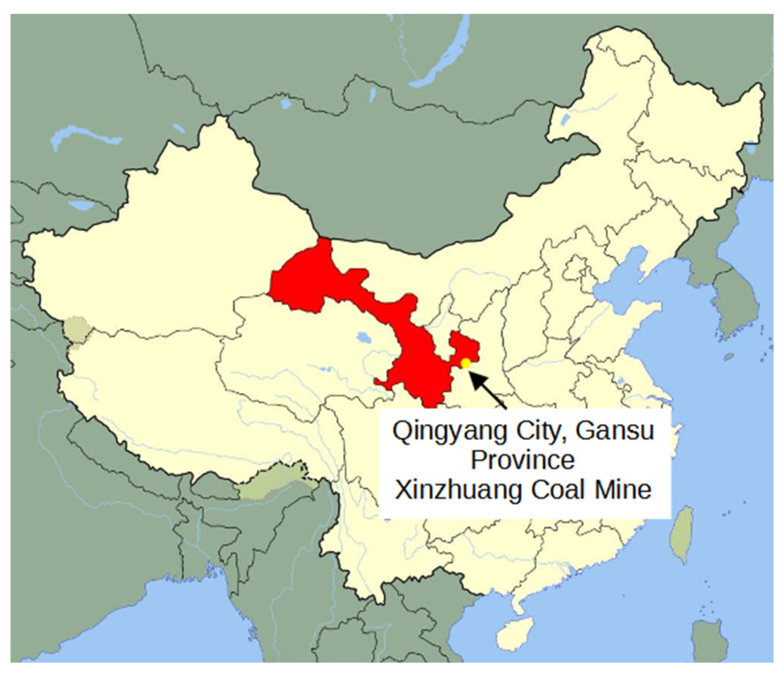
Figure 1. Coal mine location map.
Water 17 02492 g001
Figure 2. Rock sample production.
Water 17 02492 g002
Figure 3. FRTX-500 low-temperature creep tester.
Water 17 02492 g003
Figure 4. The −10 °C triaxial creep curve for frozen sandstone.
Water 17 02492 g004
Figure 5. Acoustic emission under creep conditions in saturated frozen sandstone with σ3 = 6 MPa and T = −10 °C.
Water 17 02492 g005
Figure 7. Spatial distribution of creep damage variables in saturated frozen sandstone with σ3 = 6 MPa and T = −10 °C.
Water 17 02492 g007
Figure 8. Ideal full variation curve of damage variable.
Water 17 02492 g008
Figure 9. Variation curves of damage variable D with n at different creep stages.
Water 17 02492 g009
Figure 10. Creep curves of fractional-order viscosities for different values of β.
Water 17 02492 g010
Figure 11. Fractional-order-based nonlinear creep model for cryo-damaged frozen rock.
Water 17 02492 g011
Figure 12. The −10 °C nonlinear regression effect of the fractional-order model for saturated frozen sandstone at different perimeter pressures.
Water 17 02492 g012
Figure 13. Creep curves for different stress levels.
Water 17 02492 g013
Figure 14. Creep curves for different fractional-order derivative ζ values.
Water 17 02492 g014
Figure 15. Creep curves for different fractional-order derivative γ.
Water 17 02492 g015
Figure 16. Creep curves for different damage parameters.
Water 17 02492 g016
Table 1. Peak strength of saturated sandstone under different confining pressures.
T/°Cσ1/MPa
σ3 = 0 MPaσ3 = 2 MPaσ3 = 4 MPaσ3 = 6 MPa
−1025.1931.1337.2943.01
Table 2. Fractional model parameter identification of saturated sandstone at −10 °C under different confining pressures.
Confining Pressure
MPa
Axial Compression
MPa
E11ζE2D2γR2
GPaGPa/hGPaGPa/h
00.2σ10.01630.19170.00372.140798.99
0.3σ10.01640.46740.00931.523897.95
0.4σ10.01570.50020.02400.995996.94
0.5σ10.01550.53770.36420.14380.44300.10020.154197.99
0.6σ10.012340.55140.46510.05990.99790.37710.661492.90
20.2σ10.02770.20010.00681.869898.99
0.3σ10.02760.51920.01611.230595.94
0.4σ10.02700.65020.01401.094896.73
0.5σ10.02710.70350.02350.993393.90
0.6σ10.02720.81020.07140.78140.46520.29740.427896.99
0.7σ10.02640.88120.15570.36470.78260.42710.645593.98
0.8σ10.02120.88340.40470.19680.80880.64380.792991.88
40.2σ10.03950.23230.00351.983898.98
0.3σ10.04190.52730.00781.127796.78
0.4σ10.03980.68890.01061.117293.93
0.5σ10.03740.75220.01851.018696.89
0.6σ10.03590.83130.14700.92350.48630.30450.139293.99
0.7σ10.03330.90020.26440.56720.48920.73910.684796.97
0.8σ10.02770.22890.51260.16860.99680.86500.735591.93
60.2σ10.05170.26740.00882.552398.98
0.3σ10.05470.64020.01491.287298.98
0.4σ10.04940.72640.01991.098596.83
0.5σ10.04030.85630.02531.07560.47020.16750.538093.91
0.6σ10.03490.91000.47630.20830.81020.31340.751490.25
Disclaimer/Publisher’s Note: The statements, opinions and data contained in all publications are solely those of the individual author(s) and contributor(s) and not of MDPI and/or the editor(s). MDPI and/or the editor(s) disclaim responsibility for any injury to people or property resulting from any ideas, methods, instructions or products referred to in the content.