1. Introduction
With the rapid development of infrastructure construction globally, sea-crossing bridges, wharves, and offshore wind farms have become essential components of modern transportation and renewable energy systems. However, these coastal and offshore infrastructures, e.g., the Donghai Bridge in Shanghai [
1], the Jiangsu Rudong Offshore Wind Farm located in the shallow coastal waters of the Yellow Sea [
2], the Shanghai Yangshan Deep-Water Port [
3], are often constructed on slope beds, where the natural inclination of the seabed enhances engineering challenges [
4]. For instance, the pile foundations usually employed to support the aforementioned marine structures are also designed within the coastal and offshore slope accordingly, not only facing the effects of scour caused by water flow but also enduring horizontal loads induced by vehicular traffic on the bridge deck, wind, wave–current interactions, etc. Contrary to the common assumption that the seabed is flat, such sloping bed conditions and corresponding scour-related issues add a layer of complexity to the construction and stability of these coastal and offshore pile foundations.
Unlike piles in horizontal grounds, the presence of a slope substantially reduces the lateral resistance of soil around the pile. Experimental and numerical studies have consistently shown that the lateral load capacity of piles decreases as the slope angle increases. Yang et al. [
5] conducted small-scale laboratory tests and finite element simulations on piles in slopes with varying angles. Their findings demonstrated that the deflection at the pile head increases with slope angle due to reduced soil resistance on the slope-facing side of the pile. Furthermore, they observed that soil resistance diminishes significantly at shallow depths, leading to higher bending moments in the pile near the surface of the slope. Mezazigh et al. [
6] used centrifugal modeling to show that the reduction in lateral capacity is most pronounced for piles closer to the slope crest. Studies conducted by Georgiadis et al. [
7] confirmed these findings, illustrating that the reduction in lateral resistance occurs within a distance of 5–8 times pile diameters from the crest. Beyond this range, the influence of the slope becomes negligible. Moreover, Yang et al. [
5] developed modified p–y curves based on finite element results for steep clay slopes. Their method incorporates the slope angle and the pile’s position relative to the crest, providing a more accurate representation of laterally loaded pile behavior in slopes. Similarly, Tang et al. [
8] extended the p–y curve methodology to account for slope inclination in rock slopes, emphasizing the importance of capturing the attenuation of soil resistance in the upper layers of the slope. Kumar et al. [
9] used 3D finite element analysis to study the lateral performance of piles in medium-stiff clay slopes. Their results revealed that the lateral bearing capacity diminishes as the pile moves closer to the slope crest, and the maximum bending moment occurs at shallow depths. Ma et al. [
10] performed a comprehensive numerical analysis on the lateral bearing capacity of piles embedded in clay slopes. Their study showed that the lateral bearing capacity decreased as slope angle increased, with a corresponding reduction in horizontal foundation stiffness. The findings highlighted that the maximum bending moment of piles occurred at approximately half the pile length and diminished with increasing slope angles.
In addition, scour is a complex erosional process that occurs when flowing water removes sediment from around pile foundations, often leading to significant stability challenges for pile-supported structures like bridges, wharves, and offshore wind turbines. This phenomenon is initiated when local flow velocities exceed the critical threshold required to mobilize bed materials, triggering sediment displacement and excavation around the piles. The flow–structure interaction creates horseshoe vortices at the upstream base of the pile and wake vortices downstream, both of which intensify localized erosion. Flow velocity, water depth, sediment characteristics, and the cross-sectional geometry of the foundation all contribute to the scour process in complex ways. Numerical studies have extensively investigated the effects of scour on the lateral response of piles. Li et al. [
11] conducted a finite element analysis examining the impact of scour on monopiles with different slenderness ratios. Their results indicated that local scour conditions affect the lateral bearing behavior more severely than global scour, particularly for monopiles with lower slenderness ratios, as these structures exhibit a larger reduction rate in lateral capacity as scour depth increases. Similarly, He et al. [
12] applied an advanced hypoplastic model to analyze the role of stress history in soft clay under scour conditions, concluding that ignoring stress history effects leads to an overestimation of soil stiffness and strength. Ma et al. [
13] developed a dynamic model for laterally loaded piles in layered soil using a modified Vlasov foundation model. Their findings demonstrated that as scour intensified, the natural frequencies of piles decreased significantly due to reductions in the subgrade reaction coefficient and increases in the shear coefficient. Meanwhile, Zhang et al. [
14] developed an analytical approach to predict the lateral behavior of piles in soft clay considering scour-hole dimensions. Their results emphasized that scour reduces the effective overburden pressure and undrained shear strength, leading to compromised lateral bearing capacity. Ni et al. [
15] conducted a study focusing on the lateral load capacity reduction due to scour. Their results indicate that as scour depth increases to 2.4 times the pile diameter, the lateral load capacity can decrease by nearly 50%. Additionally, the lateral response of pile groups under scour conditions has been extensively analyzed. Wang et al. [
16] conducted numerical simulations on pile groups embedded in clay and found that pile–pile interactions significantly influence lateral stiffness under scour conditions. Their study revealed that the front-row piles bear higher loads compared to rear-row piles, leading to potential overestimation of lateral resistance if scour effects are ignored. A study by Rollins et al. [
17] showed that pile groups in sandy soils experience increased local scour depths, altering lateral resistance. Numerical models incorporating the effects of scour depth and pile spacing provided more realistic predictions of pile group behavior under lateral loads. Wang et al. [
18] proposed the use of solidified soil as a scour remediation technique. Their numerical simulations indicated that solidified soil significantly improves lateral resistance by reinforcing the seabed around piles, reducing lateral displacements, and increasing ultimate load capacity. Jia et al. [
19] analyzed the effects of asymmetric scour holes on lateral pile capacity and found that the heart-shaped scour holes produced a higher bending moment, demonstrating that neglecting scour hole asymmetry can lead to inaccurate design estimations. A study by Mostafa [
20] compared local and global scour effects on the lateral capacity of the pile, showing the significance of considering scour hole dimensions in design calculations.
While extensive studies have been conducted on the lateral response of piles in horizontal grounds, onshore slopes, and horizontal beds under scour conditions, a dearth of research remains focused on the combined effects of scour and sloping seabed conditions, resulting in a lack of established design guidelines for coastal and offshore pile foundations in sloping seabed environments. This study seeks to address this critical gap by expanding upon previous experimental investigations into local scour mechanisms around cylindrical piles in sloping beds carried out by the authors [
21], further extending the scope through numerical analysis of the response of laterally loaded piles in slopes under scour conditions. The structure of this paper is as follows:
Section 2 presents the brief definition of the problem to be studied based on the mechanism of local scour around piles in slopes.
Section 3 outlines the methodology, including the establishment of a numerical model and validation procedures.
Section 4 presents the results and discussion, focusing on (i) lateral load capacity, (ii) bending moment variation along the pile depth, and (iii) pile deformation profiles. A parametric investigation into the influence of slope angle and scour depth variations is detailed in
Section 5. Finally,
Section 6 concludes the study. Unlike previous studies that typically consider either horizontal beds with scour or inclined beds without scour, this research integrates both effects within a unified framework through experimentally calibrated numerical simulations. The novelty of the present work lies in the following: (i) incorporating equilibrium scour profiles derived from physical flume tests under various slope conditions; (ii) systematically quantifying the influence of bed inclination and scour depth on the lateral stiffness, bending moment, and deflection characteristics of piles. These findings provide new insights into the mechanics of pile–soil interaction in complex offshore environments and offer guidance for offshore pile foundation design.
2. Definition of Problem
In a previous study conducted by the authors [
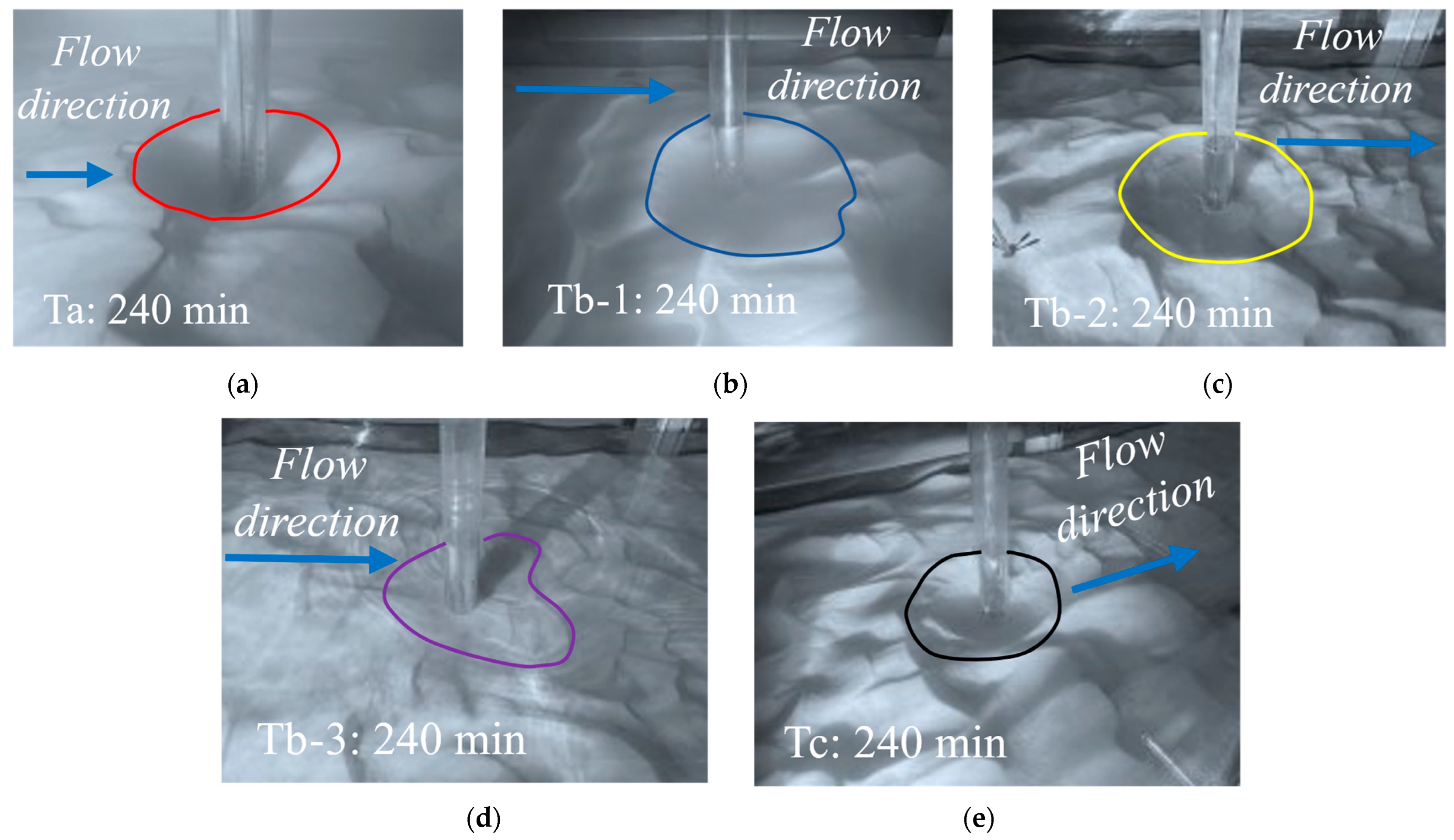
21], a series of flume experiments were conducted at the Laboratory of Hydraulic and Harbor Engineering, Tongji University, to explore the local scour mechanisms around a cylindrical pile foundation under sloping bed conditions. Three experimental scenarios were examined. Case 1, representing a horizontal bed, served as the baseline for comparison. Case 2, termed gradient slope, investigated the influence of bed inclination on scour behavior through three sub-tests involving both positive and negative slopes. Case 3, known as the transverse slope condition, assessed scour development when the flow direction was perpendicular to the bed slope. Key scour parameters, including maximum scour depth, scour extent, and bed morphology around the pile, were recorded at multiple time intervals to capture the temporal evolution of the scour process. A cylindrical pile model with a diameter of 5 cm was centrally embedded within a sediment recess, which was filled with non-cohesive soil having a median particle size of 0.15 mm. Based on the experimental time scale established in previous related studies, each test scenario was conducted over a period of 240 min to ensure comprehensive observation of the scour dynamics.
Figure 1 depicts the equilibrium scour hole geometry and bed morphology under different bed slope conditions. Ta in
Figure 1a corresponds to a horizontal bed (0° slope), serving as the baseline case. Tb-1, Tb-2, and Tb-3 in
Figure 1b–d represent gradient slopes of +5°, −5°, and −8°, respectively, demonstrating how positive and negative slopes influence scour development. Meanwhile, Tc in
Figure 1e depicts a transverse slope where the flow direction is perpendicular to the slope, introducing a distinct morphological response. Each scenario shows the interaction between flow dynamics, bed inclination, and sediment transport in shaping the final scour geometry.
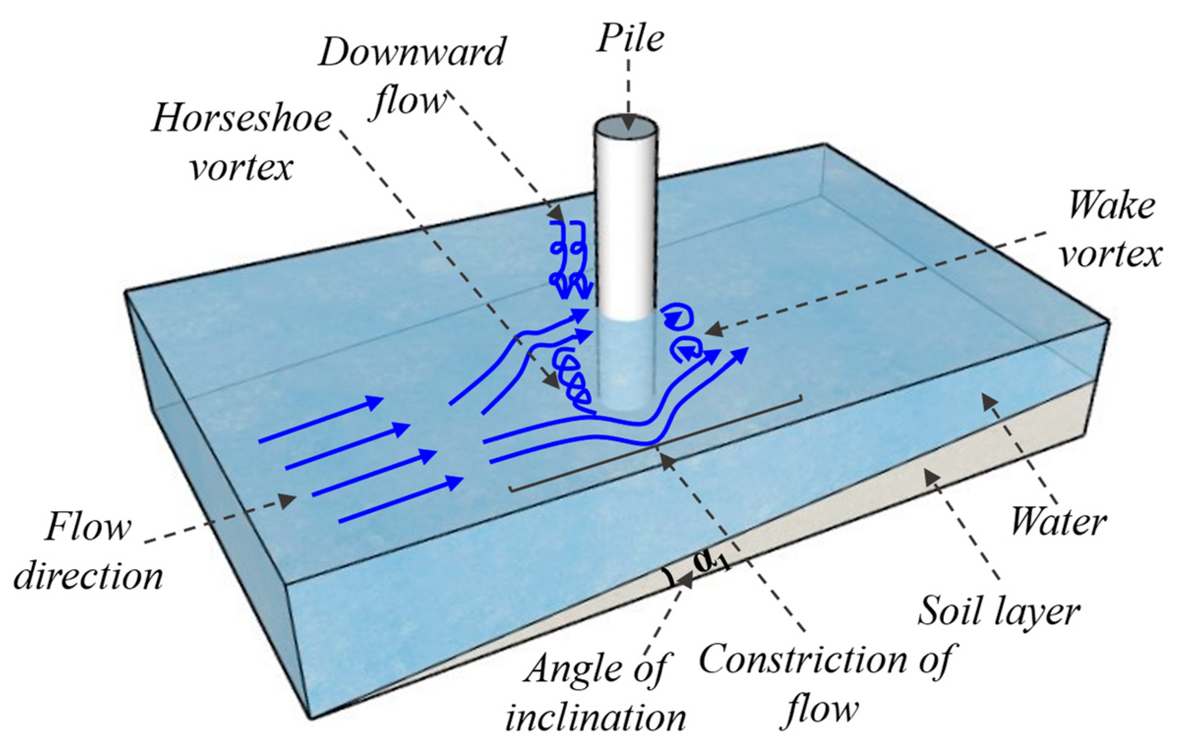
In experimental observations, it was found that the mechanism of local scour around vertical structures, such as pile foundations, differs significantly between sloping and horizontal sediment beds due to the combined influence of flow separation, vortex dynamics, and gravitational components acting on sediment transport. In sloping beds as depicted in
Figure 2, the inclined surface geometry intensifies the downward flow component, particularly on the upstream face of the pile. This amplifies the strength and penetration depth of the horseshoe vortex, thereby increasing localized scour depth. The slope angle significantly alters the flow structure, and flow acceleration occurs preferentially in the downslope direction, where gravity acts in alignment with the flow. This results in greater flow velocity and elevated bed shear stress, leading to intensified erosion and deeper scour on the downslope side. As slope steepness increases, so does the magnitude of these effects, resulting in a more aggressive scour process on the downslope face. Furthermore, the intensification of turbulent vortices, notably the horseshoe and wake vortices, is more pronounced on sloped beds. These vortices generate fluctuating pressure fields, promoting unsteady sediment entrainment.
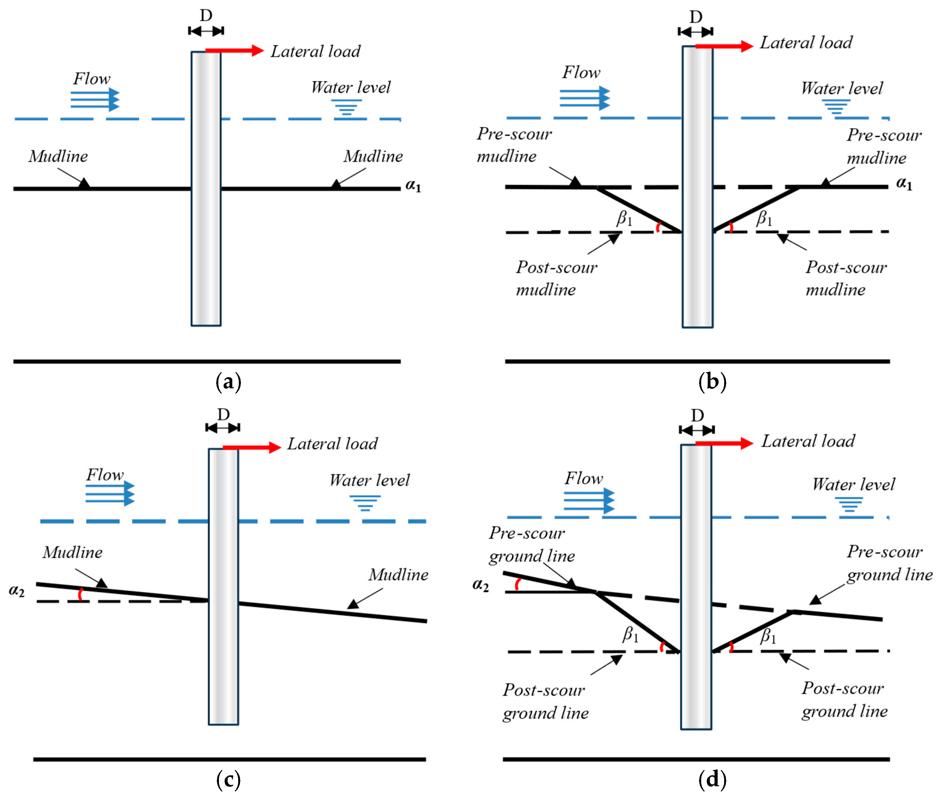
A comparative analysis is performed to assess the performance of laterally loaded piles embedded in both horizontal and sloping beds, under both scoured and unscoured conditions, as illustrated in
Figure 3. The model parameterization for this study is based on the experimental results of scour depth obtained from different slope bed conditions, including horizontal, positive inclination, negative inclination, and transverse slopes. After the scouring process reached a state of equilibrium, an inverted cone with an elliptical plan view is also used to model the scour hole according to the experimental results. In this study, the scour hole was modeled with a symmetrical slope angle on both sides of the pile, which reflects the general scour geometry observed in our flume experiments under steady flow conditions. This simplification facilitates the numerical modeling process while remaining consistent with the experimentally measured profiles. Given that previous studies have identified scour depth as the dominant parameter influencing the lateral response of piles, the potential influence of asymmetrical scour slopes was considered secondary and thus not explicitly modeled.
3. Methodology
A series of numerical models were established in both unscoured and scoured states using the ABAQUS 2020 finite element software, as presented in
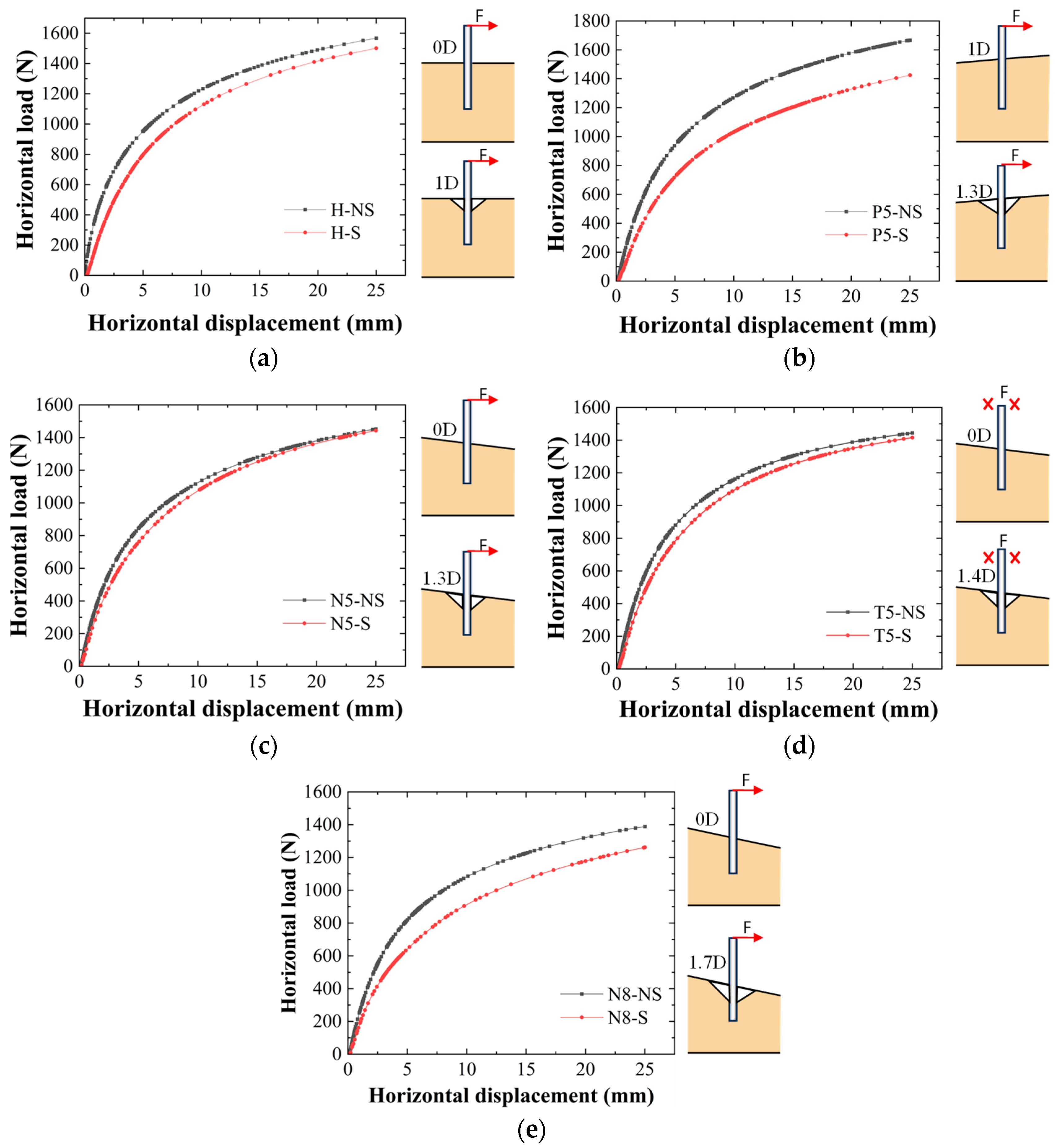
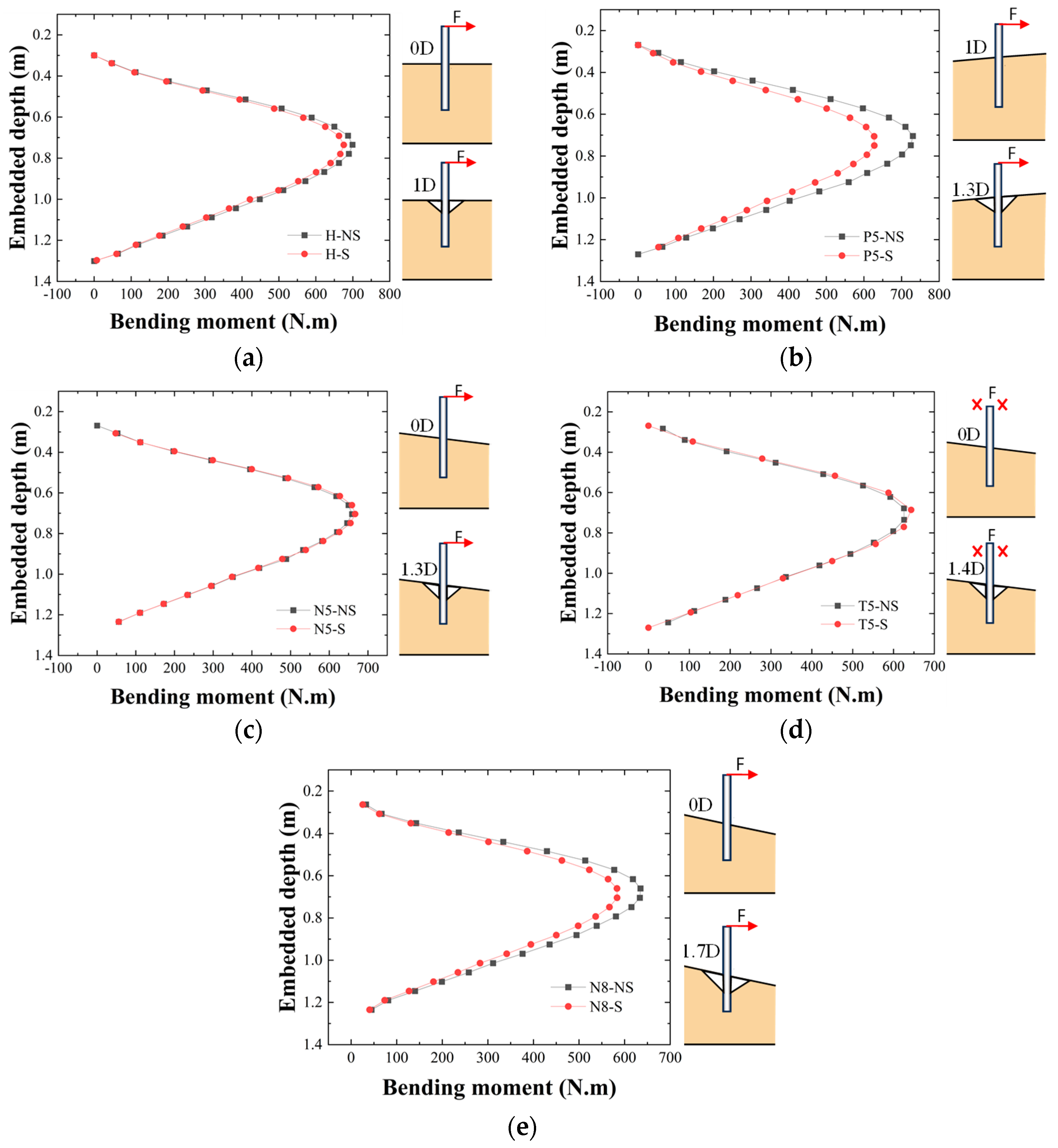
Table 1. The models represent various configurations of the bed slope and scour conditions to investigate their effects on pile lateral response. Specifically, the model for a horizontal bed without scour is denoted as “H-NS”, and for a horizontal bed with a scour hole, it is represented as “H-S”. Similarly, for a positive inclination bed at +5°, the model in an unscoured state is abbreviated as “P5-NS”, and in a scoured state, it is referred to as “P5-S”. For a negative inclination bed of −5°, the corresponding models are “N5-NS” for the unscoured bed and “N5-S” for the scoured bed. A transverse bed with a negative slope of −5° is represented by “T5-NS” in an unscoured state and “T5-S” in a scoured state. Additionally, a negative inclination bed of −8° is modeled as “N8-NS” for the unscoured bed and “N8-S” for the scoured bed. The letters H, P, N, T, 5, NS, and S represent the horizontal, positive, negative, transverse slope, the slope angle of inclination, no-scour, and scour conditions, respectively.
It is worth noting that although parameters such as scour width and scour hole slope angle can influence the scour process, their impact on the lateral response of piles is relatively limited compared to scour depth. As highlighted by Lin et al. [
22], scour depth is the most critical factor governing pile behavior under scour conditions. Therefore, the finite element models developed in this study primarily focus on the scour depth. To simplify the representation of the scour hole while maintaining reasonable physical assumptions, the slope angle of the scour hole in all models is set equal to the internal friction angle of sand, which is 32°. This assumption reflects typical scour profiles in sandy soils and allows for a consistent comparison across different seabed conditions.
Figure 4 presents a schematic diagram illustrating the finite element model setup for unscoured and scoured conditions in various bed scenarios.
3.1. Establishment of Numerical Model
This section discusses a process of how the three-dimensional numerical pile–soil model was established in ABAQUS, as illustrated in
Figure 5. The soil domain was modeled with the same dimension as that of the flume recess with a length of 2.7 m, width of 0.8 m, and height of 1.0 m. The soil was well partitioned at the center of the
x and
y coordinates to reflect the behavior of the pile at the center of the soil, which is the focus point. The pile’s geometry, with a length of 1.0 m and a diameter of 5 cm, was taken from the flume test and used in the numerical simulation. In the numerical simulation, soil density was a fundamental parameter as it directly influenced the gravitational and inertial forces acting on the soil mass. Cohesion, a measure of the attractive interparticle forces in the soil, was incorporated to define the resistance to shear deformation, particularly for cohesive sediments encountered in offshore and riverine environments. Young’s modulus of elasticity was assigned to characterize the soil’s stiffness, dictating how the material deforms under applied loads and ensuring accurate representation of stress–strain behavior. The angle of internal friction was used to define the shear strength of granular soil, crucial in determining the stability of the sloping seabed and its resistance to lateral deformation. The dilation angle was included to account for volumetric changes in the soil during shear, which plays a key role in acquiring the soil displacement patterns under loading. Poisson’s ratio was specified to describe the soil’s tendency to expand or contract laterally when subjected to axial stress, influencing the accuracy of the pile–soil interaction model.
The material properties of the soil used in this study are derived from a geotechnical investigation report for a pile–wharf engineering project in Shanghai [
23], as summarized in
Table 2. Meanwhile, the properties of the pile material are based on the findings of Ma et al. [
24], as presented in
Table 3. These sources were selected to ensure that the adopted parameters accurately represent in situ conditions and material behavior, providing a reliable basis for the analysis. Both the pile and soil models were assembled, and the pile’s embedded depth in the soil was maintained at 0.7 m in all the cases, with varying protruding distances from the surface of contact with the soil to the loading point. To ensure negligible boundary effects between the pile base and the bottom of the soil chamber, a vertical distance of 5 D was maintained for the horizontal sediment bed and 4 D for the steepest sediment bed, which is sufficient to be neglected. When modeling for scour hole cases, after the scouring process reached a state of equilibrium, a scour hole was excavated and modeled as an inverted cone with an elliptical plan view.
The “step” module in ABAQUS was utilized to set the various calculation steps involved in the simulation for the horizontal and slope sediment beds, both with scour holes. It first starts by calculating the geostatic phase of the soil, then the pile is embedded in the soil, and finally, the load is applied to the pile’s head. Two additional steps are required when simulating slope and scour holes: the slope step and the scour hole before the load are applied. These steps ensure that the initial conditions of the soil, including its slope bed and the excavation of scour holes, are accurately established before any external loading is introduced. This sequential approach allows for a more realistic representation of the physical processes occurring in the field. The soil–structure interaction (SSI) is crucial to the whole simulation process in that if not properly executed, the outcome of the results will not be accurate. To achieve that, the “interaction” module in the software was accessed to perform the necessary setup. Interactions such as pile–soil contact, slope modifications, and scour hole behavior are tracked through initialization, geostatic phase, pile placement, and slope and scour hole deactivation. Key interactions, like pile deactivation and scour hole removal, are created during specific steps and are propagated, modified, or deactivated based on the simulation requirements. This setup accurately represents the evolving physical processes, including the effects of the pile insertion and scour hole interactions with the slope and soil. In the “load” model, a gravitational force of −10 m/s
2 was applied in the geostatic step for the whole model and was propagated for all the steps. The contact friction coefficient of 0.3 was adopted based on the work of Li [
25]. As much as gapping and slippage were possible, changes in friction coefficients did not impact lateral pile reaction according to Brown et al. [
26]. Displacement constraints were implemented in the
x–
y axes around the model, with all degrees of freedom constrained at the
z-axis. A displacement-controlled loading method was utilized, applying a defined displacement to the pile head in the
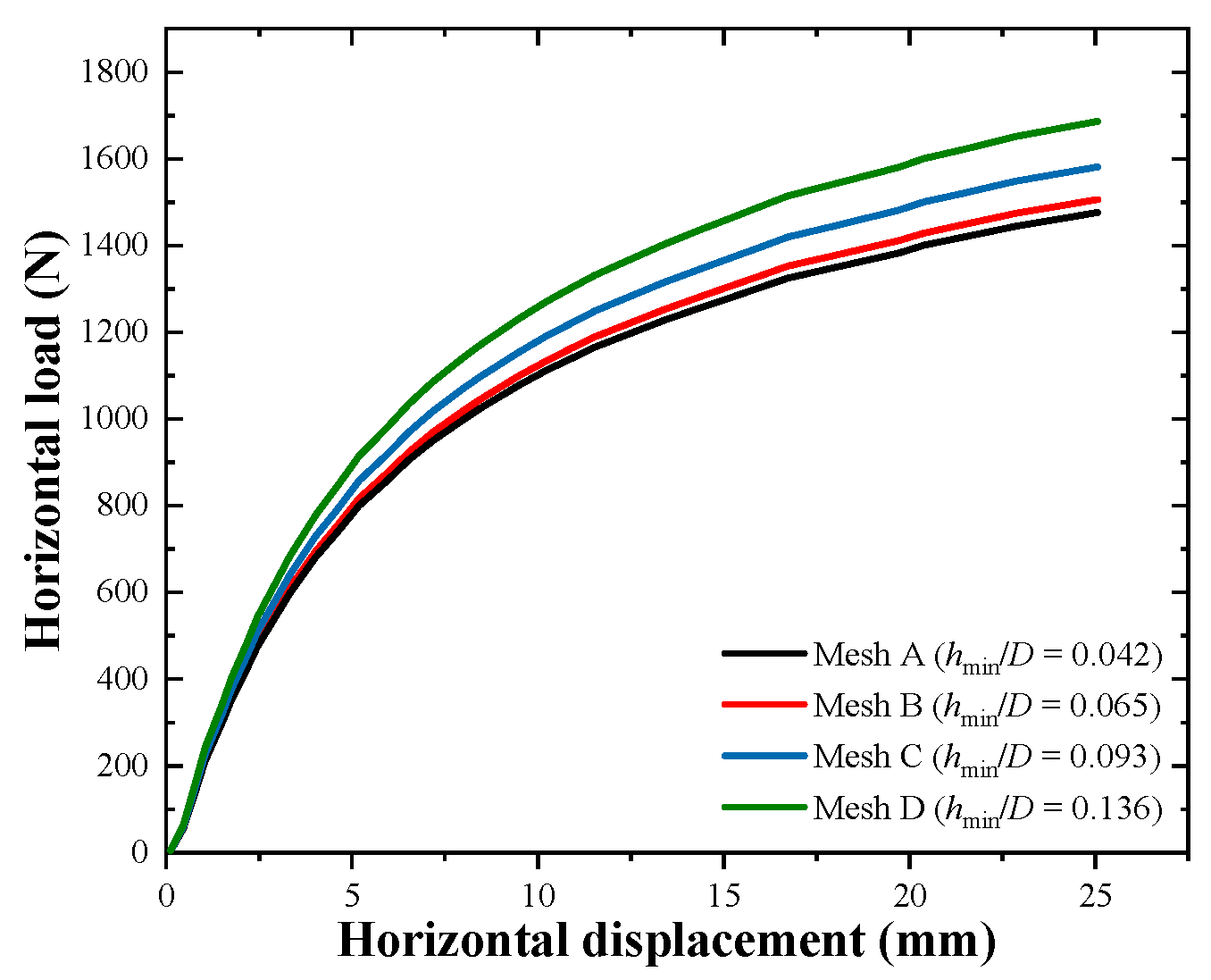
x direction through established boundary conditions. The pile head was incrementally loaded until its lateral displacement at the pre-scour ground line reached 25 mm, i.e., 0.5 D. The mesh density was increased near the pile and the soil surface to precisely reflect the stress and deformation characteristics in these critical regions. The soil and pile components were modeled using three-dimensional, eight-node, linear brick elements with reduced integration (C3D8R). Mesh sensitivity is described in detail in
Appendix A.
3.2. Validation of Numerical Model
To ensure the reliability of any numerical simulation, it is essential to validate both the model and the method used. This validation provides a strong foundation on which other researchers can base their work. In this stage, the 3D finite element model and the simulation methodology were validated through comparison with the simulation conducted by Zhang et al. [
27]. In their study, the response of a monopile under combined loading under slope conditions was investigated. Their study was mainly focused on assessing the effect of the pile’s bearing capacity under various complex loading scenarios at different leeward slope angles, such as 15°, 30°, and 45°. Notably, their study did not consider the influence of scour holes on the pile behavior, which allowed for a focused analysis of the pile response solely due to slope-induced forces.
The Mohr–Coulomb (MC) constitutive model was employed to represent the surrounding soil’s failure criterion. The MC model is a widely accepted approach in geotechnical engineering for modeling the soil’s behavior, particularly in undrained sands. This model is commonly used to predict foundations’ lateral and vertical reactions. The monopile was modeled using a linear elastic material model, a common assumption of the pile’s mechanical behavior under typical loading conditions.
For model validation, the soil–pile geometry and material properties specified by Zhang et al. [
27] were adopted directly in this study.
Table 4 presents the material properties of the soil model, while
Table 5 presents those of the pile model.
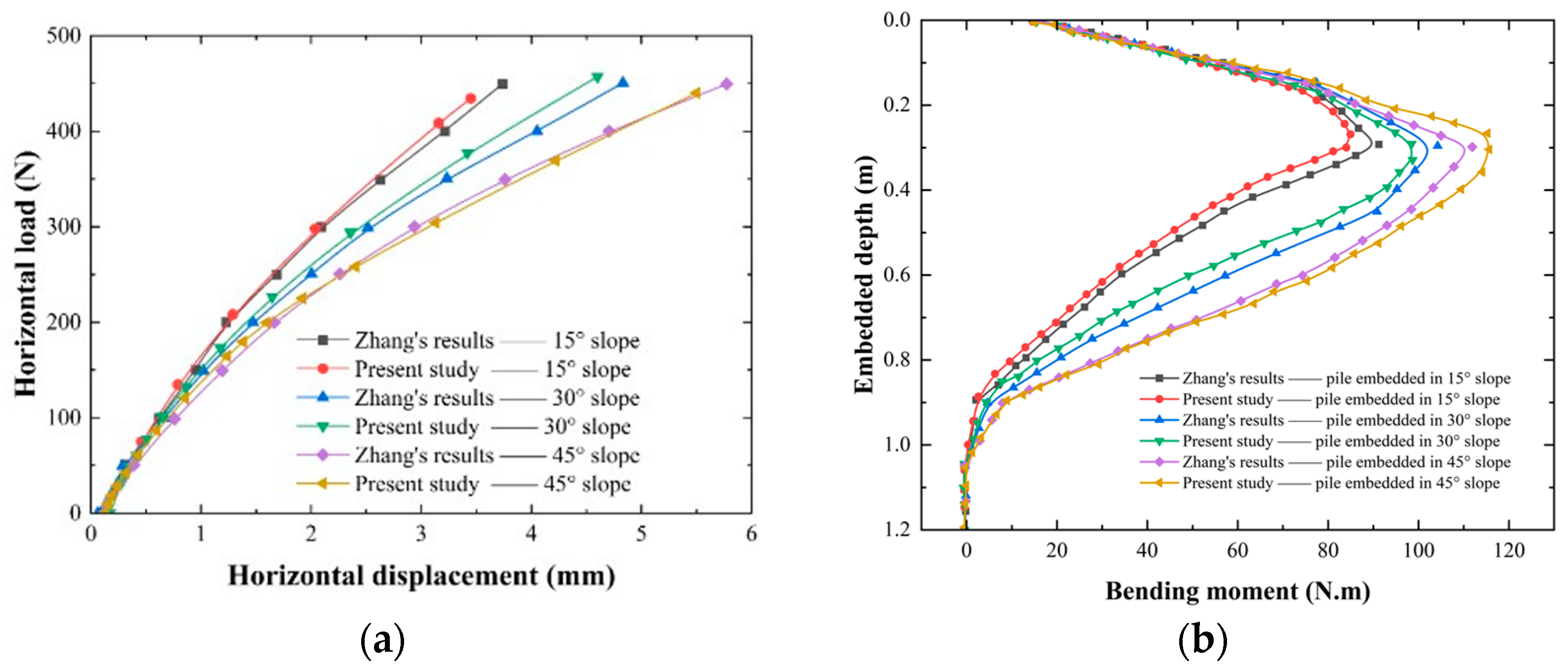
Figure 6 compares the results of their investigation and the numerical simulation conducted in this study.
Figure 6a,b represents the load–displacement relationship at the pile head and the bending moment along the embedded depth of the pile in 15°, 30°, and 45° leeward slopes in no-scour scenarios, respectively. It can be seen from
Figure 6a that the load–displacement curves and bending moment along the pile-embedded depth of the numerical simulation and the study conducted by Zhang et al. [
27] showed similar trends. When the lateral load of 450 N was applied on the pile-embedded in 15°, 30°, and 45° leeward slope, the percentage error of the maximum horizontal load in the study above and ABAQUS results correspond to 3.0%, 3.5%, and 2.1%, respectively. The percentage error of the maximum bending moments corresponds to 5.6%, 3.3%, and 7.4%, respectively. The numerical results agree with the above study and rationality of the numerical model is validated.
5. Parametric Analysis
This parametric study analyzed two scenarios to investigate the lateral response of a horizontally loaded pile: (1) the influence of bed slope angle (α) on the pile’s lateral response in an unscoured bed, and (2) the effect of scour depth (Sd) on the pile’s lateral behavior in sloped beds. The analysis evaluated unscoured (0 D) and scoured scenarios, with scour depths varying from 3 D to 4 D, where D represents the pile diameter. In every scenario, the protruding height of the pile above the bed level is consistently set at 3 D, while the embedded depth of the pile was maintained at 17 D. Consistent lateral loading was applied along the x-axis to maintain uniformity.
Case 1 concentrated on analyzing the impact of different bed slope angles on the lateral behavior of the pile under unscoured conditions. The bed slope angle was examined at −10°, −12°, and −14°. Case 2 examined the impact of varying scour depths (3 D, 3.5 D, and 4 D) at a bed slope angle of −14°, representing the steepest slope in the analysis. The scour slope angle (
β) was maintained consistently at 32° throughout. The key parameters considered in this study are summarized in
Table 6.
5.1. Impact of Bed Slope Angle on Pile Lateral Respoonse
Figure 10 illustrates the horizontal load–displacement behavior of piles embedded in sediment beds at three different slope angles: −10°, −12°, and −14°. The results clearly show that the horizontal bearing capacity of the pile decreases as the slope becomes steeper. This is because as the slope increases, the soil around the pile experiences reduced lateral confinement, which weakens the soil’s ability to resist the lateral forces applied to the pile. Among the three slopes, N10-NS achieves the highest horizontal load capacity, reaching approximately 1347 N at the upper limit of displacement. This indicates that at a shallower slope, the soil provides more lateral resistance due to better confinement, which allows the pile to resist higher lateral forces before significant displacement occurs. Conversely, N14-NS exhibits the lowest horizontal load capacity, with a maximum of around 1260 N. At this steeper slope, the soil on the downhill side of the pile is less confined, leading to lower lateral resistance and an overall decrease in the pile’s horizontal load capacity. This trend reflects the reduced lateral confinement and support provided by the soil as the slope inclination increases.
The displacement behavior further supports this observation. In shallower slopes, such as N10-NS and N12-NS, the horizontal displacement progresses steadily with increasing load, demonstrating the pile’s ability to retain its stiffness and lateral resistance throughout the loading process. This steady displacement suggests that the soil maintains sufficient stability and confinement, ensuring that the pile is able to resist lateral forces without significant deformation at a constant rate. However, for N14-NS, the displacement increases more rapidly for the same load, indicating reduced stiffness and a compromised ability to resist lateral forces. As the slope steepens, the soil becomes less stable, and the pile experiences more deformation under load due to the reduced lateral support from the surrounding soil. As the scour depth increases, the effective embedded length of the pile is reduced, thereby diminishing its lateral load-carrying capacity. Under a given pile head lateral displacement, a deeper scour hole leads to a notable reduction in the mobilized lateral soil resistance acting on the pile shaft, which in turn results in a lower bending moment response. Furthermore, with the loss of support from the upper soil layers, deeper soil strata are mobilized to resist the imposed lateral deformation. This shift in the mobilized soil resistance zone causes the location of the maximum bending moment to migrate downward along the embedded depth. This suggests that the soil on steeper slopes becomes less stable and fails earlier, particularly on the downhill side of the pile, which experiences less confinement and resistance compared to shallower slopes. The reduced stability on the downhill side is a result of soil shear strength being compromised by the slope geometry, which accelerates failure and increases displacement.
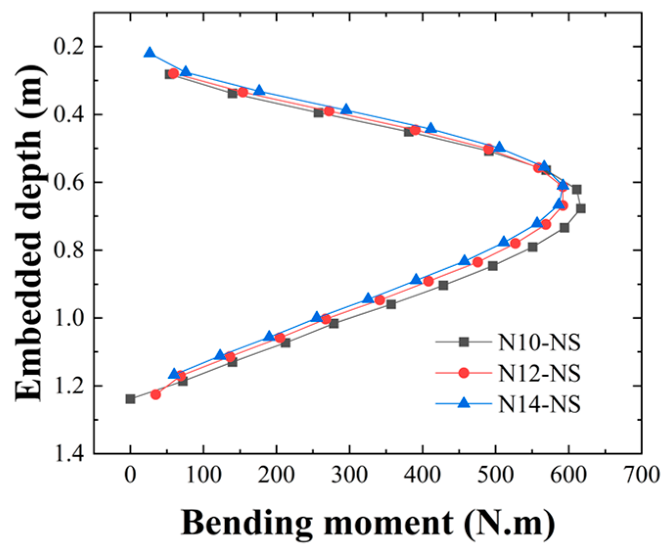
Figure 11 depicts the distribution of bending moments along the embedded depth of piles in unscoured slopes of −10°, −12°, and −14°, emphasizing the impact of slope inclination on pile performance. The peak bending moment reaches around 616 N·m for N10-NS, while it measures 592 N·m for N12-NS and 586 N·m for N14-NS. The observed reduction in the peak bending moment with increasing slope angle can be attributed to the decreased lateral confinement and resistance provided by the surrounding soil as the slope becomes steeper. As the slope increases, the passive resistance on the uphill side decreases because the soil is more inclined to move under lateral load, thereby reducing the pile’s resistance to bending. This indicates a 3.9% reduction in peak bending moment when shifting from the −10° slope to the −12° slope, followed by an additional 4.9% decrease upon moving to the −14° slope. This trend confirms that steeper slopes result in progressively lower lateral support, as the load-bearing capacity of the soil diminishes due to the reduced ability of the soil to resist lateral deformations under steep inclinations.
The magnitude of the peak bending moment exhibits considerable variation depending on the angle of the slope. In the case of N10-NS, the peak is situated nearer to the surface, whereas, for the N14-NS, the peak is positioned deeper within the pile, showing a depth increase of about 10–15% when comparing N10-NS and N14-NS. This shift in peak bending moment depth can be explained by the fact that steeper slopes cause less confinement of the upper portion of the pile. As the slope increases, the pile must rely on deeper soil layers to resist lateral forces because the shallower layers provide less lateral support due to the soil’s reduced shear strength near the surface. This suggests that when dealing with steeper slopes, the pile must engage lateral resistance at greater depths because of decreased soil support close to the surface.
The reduction in the post-peak bending moment occurs more gradually in steeper slopes, suggesting a wider distribution of lateral forces throughout the length of the pile. This gradual reduction in bending moment in steeper slopes reflects a more uniform spread of the applied lateral load across a greater depth of the pile. As the slope increases, the soil around the pile becomes less capable of providing localized resistance, which results in a more distributed failure mode and a slower decrease in bending moment post-peak. Conversely, in N12-NS, the bending moment diminishes more swiftly after reaching its maximum, indicating a more concentrated distribution of lateral forces. This sharper decline in bending moment suggests that, at this intermediate slope, the pile experiences a more concentrated resistance at certain depths, likely due to the balance between available lateral resistance and the initial confinement provided by the soil. The findings highlight the crucial impact of slope angle on the magnitude and distribution of bending moments throughout the depth of the pile.
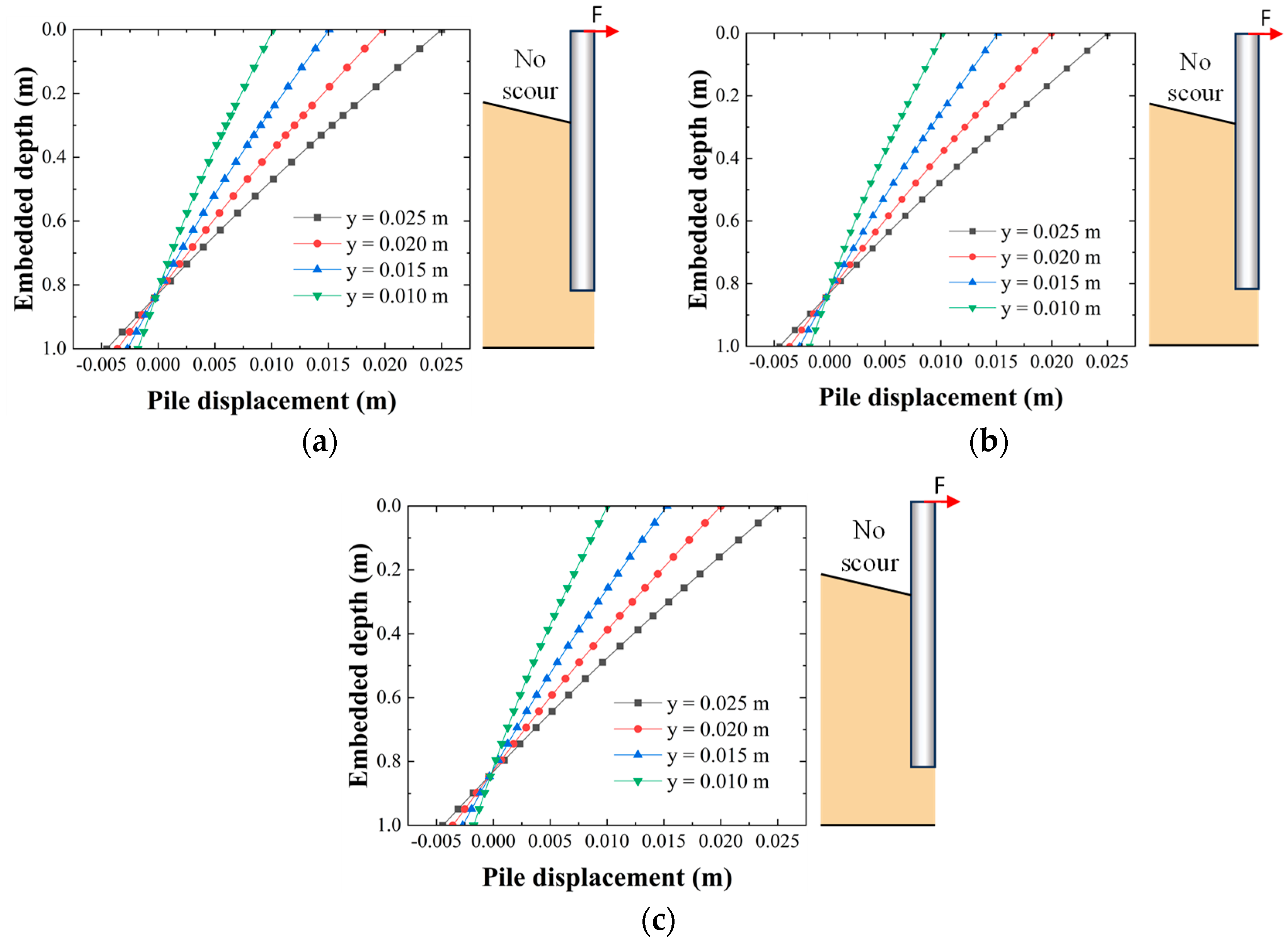
The lateral deflection of the pile at different embedded depths in slopes of −10°, −12°, and −14° under unscoured conditions is depicted in
Figure 12 a–c, respectively, demonstrating varying pile head displacements from 0.010 m to 0.025 m. The deflection profiles across all scenarios reveal a deformation mechanism primarily characterized by rigid rotation, with the rotation point’s position descending as the slope’s inclination rises.
In N10-NS, as presented in
Figure 12a, the rotation point is found around 0.8 m beneath the pile head, suggesting that the soil confinement is adequate to restrict lateral movement at greater depths. In N12-NS, as shown in
Figure 12b, the rotation point moves slightly deeper to approximately 0.85 m, indicating a decrease in lateral soil resistance due to the slope inclination. In contrast, N14-NS in
Figure 12c shows a more significant deflection profile, with the rotation point descending further to about 0.9 m, suggesting reduced lateral soil support and heightened pile deformation close to the surface. The findings reveal that with an increase in slope inclination, there is a greater extent of lateral deflection along the pile, while the rotation point shifts downward as a result of diminished soil confinement and heightened demands of pile–soil interaction.
5.2. Impact of Scour Depth on Pile Lateral Behavior
Figure 13 depicts the load–displacement response of a pile embedded in a −14° slope bed, subjected to different scour depths of 3 D, 3.5 D, and 4 D. The results indicate a gradual decrease in lateral capacity with increasing scour depth. This gradual reduction can be attributed to the loss of soil around the pile caused by scour, which significantly weakens the lateral confinement provided by the surrounding soil. As the scour depth increases, more soil is removed from the pile’s vicinity, reducing the ability of the soil to resist lateral forces. In N14-3D, the pile shows the greatest lateral capacity, reaching around 1208 N at a horizontal displacement of 25 mm, demonstrating adequate soil–pile interaction and resistance even with the slope present. At this scour depth, the pile still benefits from sufficient surrounding soil support, which enables it to resist lateral forces effectively. The slope angle has a relatively minor impact on the lateral resistance in this case, as the soil remains mostly intact around the pile.
At a scour depth of 3.5 D in N14-3.5D, the lateral capacity diminishes to 1182 N, reflecting a 2.2% reduction due to sediment loss around the pile, which decreases the lateral soil confinement. The lateral capacity of the pile reduces to 1123 N for the 4 D scour depth, indicating a 7.0% decrease relative to the 3 D scenario. This more significant reduction in lateral capacity at the 4 D scour depth underscores the cumulative effect of increased sediment loss. At this deeper scour depth, not only is the soil around the pile more extensively eroded, but the pile also experiences less lateral support from the surrounding soil at greater depths.
The findings indicate that an increase in scour depth reduces the soil confinement and lateral resistance of the pile, resulting in a greater need for the soil layer to withstand lateral loads. As scour progresses, the need for the remaining soil to resist lateral forces increases, but the capacity to provide this resistance diminishes due to erosion and reduced lateral confinement.
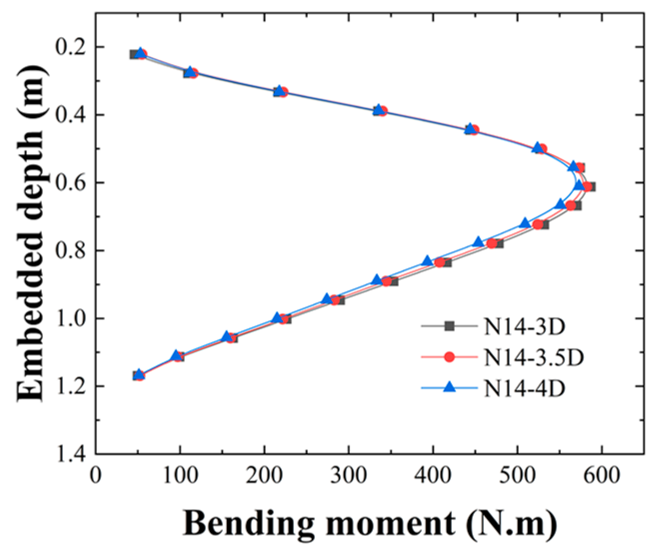
Figure 14 shows the bending moment distribution along the embedded depth of the pile in a −14° slope for scour depths of 3 D, 3.5 D, and 4 D exhibits a uniform trend, where the bending moment rises to a maximum before decreasing toward the pile head. This general trend is typical of the pile’s bending response to lateral forces, as the pile’s resistance to lateral loads increases with depth initially, reaching a peak bending moment, and then decreases as the resistance from the soil diminishes closer to the pile head. The maximum bending moment in N14-3D is observed at around 0.83 D beneath the pile head, attaining a peak value of 587 N·m.
As the scour depth reaches 3.5 D in N14-3.5D, the peak bending moment moves marginally deeper to 0.85 D and decreases to 582 N·m, indicating a 0.9% reduction in magnitude. The slight shift in the peak bending moment deeper into the pile reflects the fact that, with increasing scour, the pile’s interaction with the surrounding soil becomes weaker at higher levels, forcing the pile to engage with deeper soil layers to counteract lateral forces. The 0.9% decrease in the bending moment signifies that the pile’s ability to resist lateral loads is reduced due to the erosion of the soil near the surface.
In N14-4D, the maximum bending moment shifts further down to 0.87 D and reduces to 573 N·m, resulting in a 2.4% decrease compared to the 3 D scour depth, showcasing the critical impact of scour depth on the performance of piles. The further shifting of the maximum bending moment to a greater depth and the larger reduction in magnitude indicate that the loss of soil around the pile significantly reduces the lateral resistance, forcing the pile to engage with deeper layers of soil for lateral support. The 2.4% reduction is more pronounced, showing a clearer effect of scour erosion on the pile’s bending resistance. The downward movement of the maximum bending moment indicates a decrease in lateral support from the surrounding material as the depth of erosion increases, necessitating the engagement of deeper layers to counteract lateral forces. Moreover, the decrease in the bending moment’s magnitude shows the gradual reduction in the interaction between the soil and the pile as a result of sediment loss.
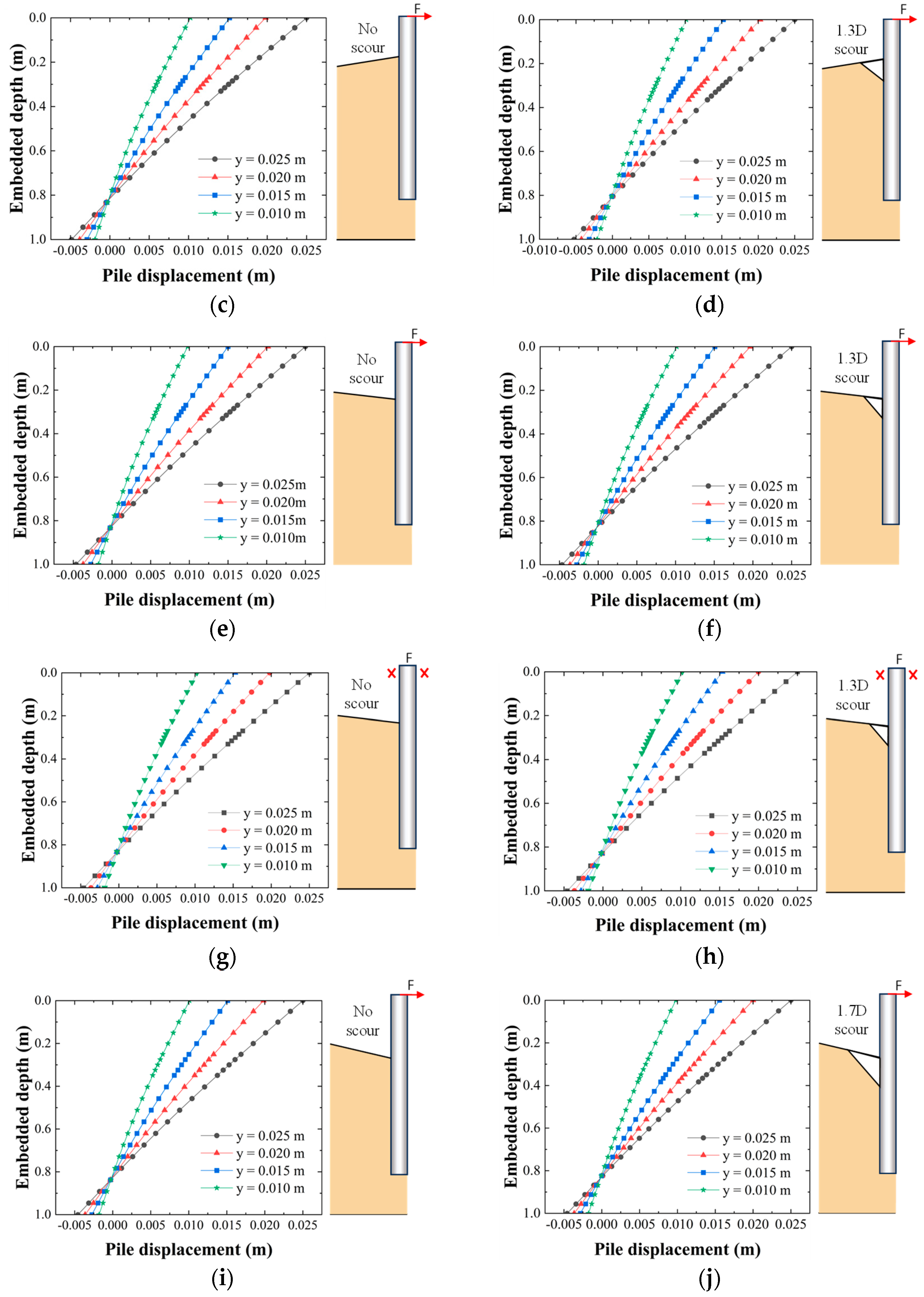
Figure 15 depicts the lateral deflection profiles of a pile situated in a −14° slope under scour depths of 3 D, 3.5 D, and 4 D, illustrating the gradual influence of scour depth on the pile’s structural behavior and the interaction between the soil and the pile. In N14-3D, the pile demonstrates a rigid rotation mode, with the rotation point situated roughly 0.85 m beneath the pile head, as shown in
Figure 15a. This demonstrates sufficient soil confinement, which efficiently counteracts lateral loads and reduces deformation at the embedded depth.
In N14-3.5D, as depicted in
Figure 15b, the rotation point decreased to around 0.88 m, suggesting a decrease in soil confinement and stiffness. The deflection of the pile is more evident as one moves deeper, with significant increases observed near the top and throughout the upper embedded section. This development indicates a reduced capacity of the adjacent soil to support the pile during lateral forces.
In N14-4D, the rotation point decreases to about 0.91 m, resulting in a notable increase in deflection throughout the entire length of the pile, as depicted in
Figure 15c. The decrease in soil resistance at this scour depth results in increased pile deformation and a transition from rigid to a more distributed rotational behavior. The rise in scour depth leads to diminished lateral soil confinement, resulting in a corresponding increase in deformation magnitude and an expanded load transfer zone. The changes in deflection profiles demonstrate that greater scour depth reduces the soil’s capacity to offer effective resistance, lowers the rotation point, and increases pile deformation.
6. Conclusions
In this study, a numerical investigation of the lateral response of piles embedded in sloping beds subjected to local scour was conducted using ABAQUS, building upon experimental findings from previous studies on the mechanism of local scour around cylindrical coastal pile foundations in sloping bed conditions. The Mohr–Coulomb (MC) constitutive model was adopted to represent the surrounding soil’s failure criterion. The numerical model developed in this study was validated through comparisons to previous work conducted by other researchers on the lateral response of a pile embedded in slopes. Subsequently, a parametric study was undertaken to investigate the influence of slope angle on unscoured bed conditions and varying scour depths in slope beds on the lateral response of the pile. Based on the numerical investigation conducted, the main conclusions from this study are as follows:
The bed slope significantly influences the pile’s lateral response. On a horizontal bed, uniform lateral resistance ensures stable load distribution. However, on a negatively inclined bed, the interaction between the pile and the surrounding sediment weakens, reducing both lateral load capacity and bending moment. This results in lower overall resistance and stability.
Increasing scour depth further decreases the pile’s lateral bearing capacity, especially on steep negative slopes. As scour deepens, the soil support around the pile is gradually undermined, leading to a more pronounced reduction in resistance. This effect is more severe in sloped beds, where the combined influence of slope and scour amplifies the loss of lateral stability.
The direction of the bed slope plays a key role in the pile’s lateral behavior. A positively inclined slope enhances lateral resistance and bending moment, providing more favorable structural conditions. In contrast, a negatively inclined slope weakens the pile’s ability to resist lateral loads, reducing overall stability and load-bearing efficiency.
While scour depth and bed slope cause minor shifts in the pile’s rotation points, their overall effect on rotational behavior remains limited. Moreover, these findings suggest that when designing piles in sloping seabed environments prone to scour, a conservative reduction factor should be applied to the lateral capacity prediction, and remedial measures such as solidified soil or riprap protection may be adopted to mitigate capacity degradation.
Design Recommendation
The findings of this study underscore the critical importance of accounting for seabed slope orientation and local scour depth in the design of pile foundations for coastal structures. In particular, designers should exercise caution when dealing with negatively inclined seabed, as such slopes significantly weaken the pile–soil interaction, leading to reduced lateral resistance and bending capacity. When combined with deep scour, the structural stability of piles may be severely compromised. Therefore, for sites with adverse slope conditions, conservative design approaches are recommended, including increased pile embedment depth or enhanced lateral support measures.
Conversely, positively inclined slopes were found to enhance lateral resistance and moment capacity, suggesting that favorable slope geometries may contribute to more efficient and stable pile behavior. These conditions can be strategically utilized during site selection or in planning scour protection strategies. In addition, while local scour alters the load transfer mechanism and causes moderate shifts in pile rotation points, its primary impact lies in reducing lateral stiffness and load-bearing capacity, especially under sloped seabed conditions. Thus, incorporating realistic scour profiles—particularly for sloped seabed—into early-stage design assessments is essential for achieving reliable and robust foundation performance.


