Article

Research on an Underwater Target Classification Method Based on the Spatial–Temporal Characteristics of a Flow Field

1
College of Mechanical Engineering, Tianjin University of Science and Technology, Tianjin 300457, China
2
Tianjin Key Laboratory of Integrated Design and Online Monitoring of Light Industry and Food Engineering Machinery and Equipment, Tianjin 300457, China
*
Author to whom correspondence should be addressed.
Water 2025, 17(13), 2006; https://doi.org/10.3390/w17132006
Submission received: 27 May 2025 / Revised: 1 July 2025 / Accepted: 2 July 2025 / Published: 3 July 2025
(This article belongs to the Special Issue Hydrodynamics Science Experiments and Simulations, 2nd Edition)

Abstract

In order to solve problems such as recognition of blind areas which exist in traditional technology in underwater near-field target sensing, this paper constructs an underwater robot target sensing model based on the fish lateral line sensing mechanism and adopts CFD simulation technology to analyze the perturbation characteristic law of the pressure signal in the flow field around the underwater robot. By extracting the pressure signal following the bionic lateral line on the surface of the underwater robot as the target recognition information, the SVM multi-target recognition model is trained and built to realize the perception and recognition of the structural features and attitude features of the underwater robot. The results show that the structural features and attitude features of the underwater robot can be recognized by using the time-domain waveform structural features and spatially symmetric distribution features of the pressure coefficients, and the recognition accuracy can reach over 90%, which reveals the principle of target feature resolution based on the sideline perception signals of the fish nerve center.

1. Introduction

The ocean is an indispensable part of national strategic deployment; the future of marine environment detection and underwater security will gradually shift to an unmanned, intelligent, and clustered approach, so the use of cost-effective and covert Autonomous Underwater Vehicles (AUVs) for underwater detection has been widely adopted by countries around the world. Underwater sensing technology is a prerequisite and technical guarantee for all marine activities, and it has also become a hotspot for technical difficulties and scientific research in underwater research in recent years.
Acoustic and optical systems are currently the main means of information interaction for AUVs; however, optical perception limits their application ranges in underwater environments due to their limited imaging quality and the influence of water turbidity [1,2,3,4]. Acoustic systems face problems recognizing blind zones and can be easily exposed when detecting near-field targets in complex environments, so their perception accuracy and effectiveness are affected. Fish have formed a unique tactile perception organ, the lateral line system, in their long-term evolutionary process, as shown in Figure 1, which is mainly composed of the epineural mound and the tubular neural mound. When the surrounding flow field undergoes perturbation and change, the epineural mound is able to perceive information such as the velocity and direction of the water flow, and the tubular neural mound mainly produces fluctuating information such as the flow field acceleration. This signal response is transmitted to the central system to realize the functions of information interaction, prey tracking, map localization, maneuvering obstacle avoidance, target recognition, etc. [5,6,7], providing a bionic reference mechanism for the development of new underwater sensing technology.
Current research on bionic laterals for underwater target recognition focuses on nonlinear dynamic modeling of flow field signals and machine learning recognition algorithms. For example, Ahrari’s team investigated the dipole localization model in three-dimensional space using a two-layer optimization approach [8]. Shahzad Ashraf et al. developed a confined energy depletion (CED) opportunistic routing (OR) mechanism, and achieved the energy-saving performance of signal transmission in underwater sensing networks [9]. Zhang Yong analyzed the time–frequency distribution characteristics of the dipoles producing pressure variations in different advective directions, and proposed a method for underwater advective target direction identification using convolutional neural networks to train pressure sensor signals [10]. Tuhtan et al. proposed a fish passage classification and identification method based on the flow field measurement signals from an artificial lateral line system [11]. Lin Xinghua et al. proposed a spatial distribution localization method and amplitude fluctuation localization method for flow field signals based on the potential flow theory by using circular, triangular, and square winding flow field information [12]; by analyzing and extracting the chaotic features and power spectrum features of the flow field signals, they realized the accurate identification of the target structure and attitude based on the support vector machine model [13,14]. Liu Guijie et al. used a BP neural network algorithm to accurately identify the flow velocity as well as the incoming flow angle of the flow field with the hydrostatic pressure data of cylindrical, boxfish, and other models in different flow field environments [15]; and data-driven algorithms, such as Random Forests and support vector machines, were used to achieve the prediction of vibration source shapes and sizes based on the flow field signal sensing [16]. Hu Qiao et al. proposed a sensor array optimization arrangement method combining a Bayesian probabilistic model and sequential heuristic algorithm, which reduced the probability of detecting the interference region at non-target locations to less than 1% [17]. Ghommem et al. used CFD numerical simulation to investigate the relationship between the flow field structure and propulsive force generated by fish-like swimming and Strong’s Halter Constant, which reveals the fish’s swimming dynamic law [18]. Xie Guangming et al. investigated the vortex wake of a robotic fish by inverse Kamen vortex street analysis based on the boxfish imitation sideline system [19]; Yanagitsuru et al. investigated the flow parameters and pressure gradient around an underwater vehicle by means of pressure sensors and found that the form of the distribution of the sensors in the bow of the chamber did not have much effect on the information of the flow field [20]. Using a box-like triggerfish robotic fish and an artificial lateral line system, Zhai Fanyu et al. derived the relationship between the amount of dynamic pressure variation on the body surface of the robotic fish and the main motion parameters [21]. Q Yang et al. proposed a C-sensor inspired by a fish lateral line tube system based on a C-array composed of a fish lateral line tubing system, which showed a significant increase in localization accuracy and multiple dipole detection capability, reducing the average localization error by 78% [22]. Luo et al. demonstrated an excellent capability in sensing underwater targets by constructing an artificial neural network model to correlate ALLs with the sensed target features; this artificial lateral line system demonstrated excellent capability in sensing underwater targets [23].
It can be seen from the above research that although the applied research of bionic lateral line tactile perception started late, with the rapid development of artificial intelligence technology, significant progress has been made in underwater target identification and localization methods, which lays a good foundation for future research in this field. But at the same time, it can also be seen that the current research objects are mostly ideal targets such as dipoles, ignoring the effects generated by the target’s own structure and moving parts such as propellers, which is the most important source of flow field perturbation in underwater target tracking, thus making the current bionic haptic perception methods and their practical application a huge gap. To this end, this paper constructs a full-attachment model based on the solid structure of a SUBOFF submarine, takes dual-engine target tracking as the application background, builds a two-way coupling bridge between the target features and the flow field disturbance features by carrying out research on the bionic haptic perception mechanism of a fish lateral line, and extracts the pressure signal following the AUV surface on the “lateral line” as the target recognition information, trains and establishes the bionic tactile perception method, and then builds the target recognition information. By extracting the pressure signal from the “sideline” on the surface of the following AUV as the target recognition information, we train and establish a SVM recognition model to realize the perception of the structural and attitude features of the target AUV and provide a kind of biomimetic tactile sensing technology for the near-field target covert detection.

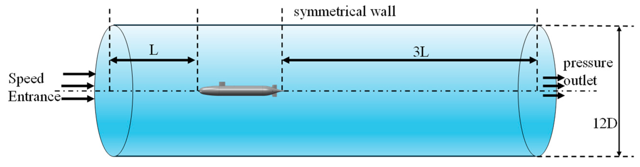
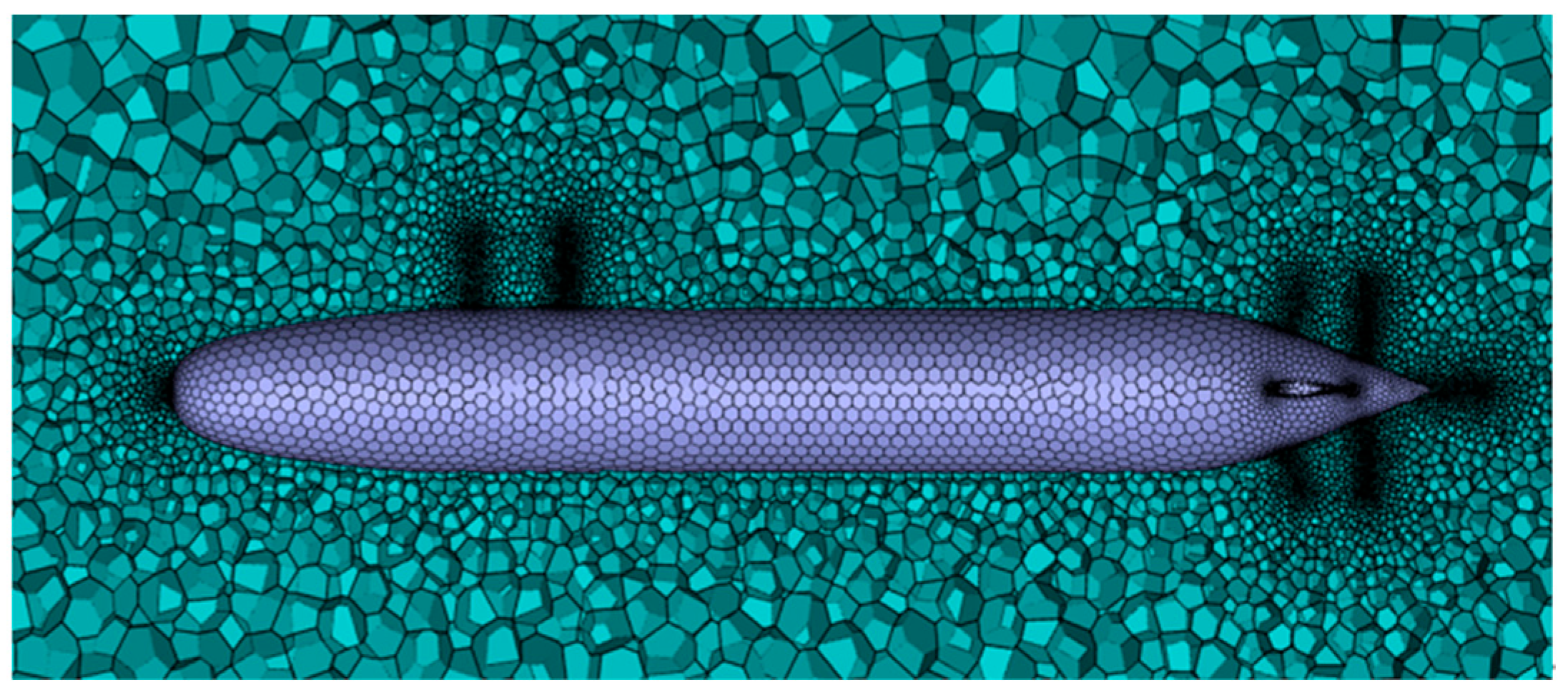
2. Model Building and Simulation Calculation

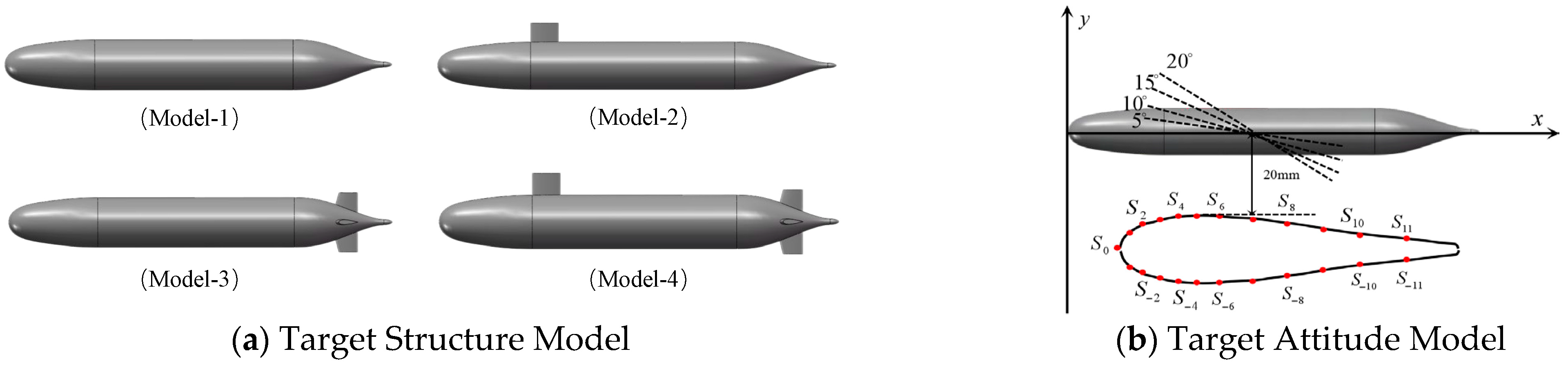
2.1. Model Construction and Description

In this paper, based on the external dimensions of a SUBOFF submarine, the main part consists of three parts: the main hull, the command deck, and the tail, and the main hull consists of four parts: the bow section, the hull section, the transom section, and the de-flowing section. The exterior contour curve is shown in Figure 2a, where the horizontal axis coordinate represents the axial coordinate of the ship body and the vertical axis represents the radial coordinate of the ship body. According to the line function of the SUBOFF submarine structure, an AUV 3D model is constructed, and in order to facilitate the discussion of the AUV motion performance, this paper adopts the carrier coordinate system (O--XYZ), as shown in Figure 2b.
The computational domain of CFD simulation is a cylindrical structure. In order to simulate the AUV navigating in a broad flow field environment, a wake flow field can be fully developed. Meanwhile, considering the economy of computing resources, the computational domain size was set to 5 L × 12 D (where L is the total length of the AUV model and D is the hull diameter). Within this domain, the inflow section length ahead of the AUV model is L , and the outflow section length downstream is 3 L . By comparing with the experimental results in the literature [24], it is proved that the above-mentioned calculation domain size can accurately simulate the flow field distribution around the AUV. In order to create a uniform flow field environment, the velocity inlet of constant size ( u x = U = 1 , u y = 0 ) is used as the inlet boundary of the computational domain, the outlet boundary is used as the pressure outlet ( P = 0 ), the boundary is used as a symmetric wall ( u x / y = 0 , u y = 0 ), and the surface of the target body is used in the no-slip rigid wall condition, as shown in Figure 3.
The pre-processing link in the process of CFD solving the dynamics of the flow field needs to realize the discretization of the space through the mesh division to form a physical model for numerical computation, and then carry out numerical computation of the Navier–Stokes equations. In order to avoid the influence of grid mesh quality and quantity on the simulation results, this paper adopts the uncertainty analysis method proposed by Stern et al. to analyze the mesh independence [25]. A grid-increasing function is built to mesh the computational domain Ω , which is shown in Equation (1). The surface of the target is meshed with χ min , and the further domain is meshed with χ ( i ) . The ratio of the grid size between two adjacent layers is δ , 1.2 in this paper, and the outside surface of the computational domain Ω is meshed as χ max .
χ ( i ) = δ · χ min χ min χ ( i ) χ max
According to the above meshing strategy, the key factor affecting the number and quality of meshes lies in the size of the first layer of meshes closest to the target body χ 1 , so five mesh sizes were used for comparative analysis. The orthographic projected area of the target body was S = 2.2 m 2 , the five grid sizes were set as s i = i × S / 1000 , and the drag coefficient C d generated by the AUV at 20 knots was used as the characterization parameter. The obtained analysis results are shown in Table 1.
As can be seen in Table 1, the drag coefficient gradually decreases with the finer grid division, but when the grid size χ 1 = s 1 , the drag coefficient has a small amount of change with χ 1 = s 2.0 , and the rate of change is only 0.696%, but the number of grids increases more than 4 times, resulting in high computational resources and time costs. Therefore, in order to balance the computational accuracy and computational cost, the minimum grid size χ 1 = s 2.0 is used in this paper, and the resulting grid distribution is shown in Figure 4.
Since the Reynolds number generated by the SUBOFF submarine’s normal navigation underwater exceeded the critical Reynolds number, the simulation was carried out using a turbulence model, in which the turbulence model is described by the modified RNG k-ε turbulence equation. In the modified RNG k-ε turbulence equation, the generation term coefficients C ε 1 of the C μ or ε equations are further adjusted to improve the prediction of rotational and separated flows. In the numerical discretization method, this paper adopts the three-dimensional solver in Fluent fluid simulation software (Ansys Fluent 2019 R3) to solve the above physical model, the solution process adopts the non-constant stealth algorithm, and the fluid is assumed to be an incompressible continuum medium during the simulation. The near-wall surface is treated by strengthening the wall function to solve the flow at the wall, and the pressure–velocity coupling is achieved with the SIMPLEC method, which is discretized by the second-order windward format; a smaller under-relaxation factor is used, and the convergence condition is that the residuals of the calculations are all less than 1 × 10⁻⁴. Meanwhile, the drag coefficients on the model are monitored, so that when the change in drag coefficients in the range of 0.001, it can be considered that the calculation results have converged.

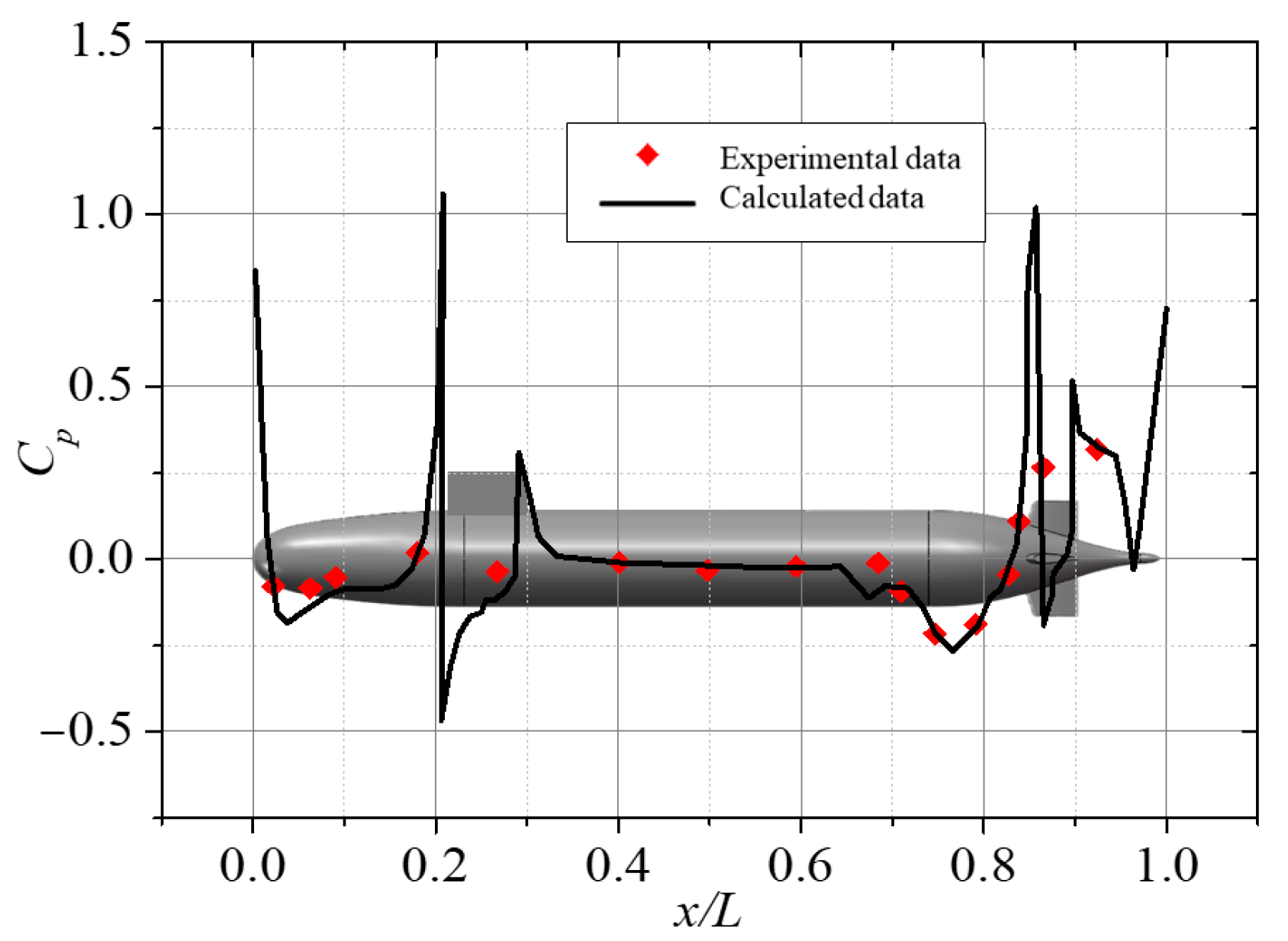
2.2. Calculation Method Validation

In this paper, the reliability of the above numerical calculation scheme is firstly verified by using the pool towing test data of the SUBOFF fully attached hull model conducted by David Taylor Naval Ship Research and Development Center, Carderock, MD, USA. The pressure coefficients C p of the hull at the upper half edge of the center longitudinal surface are compared with the relative positions of the test results, and the results obtained are shown in Figure 5. From the figure, the distribution of the submarine’s surface pressure coefficient C p is highly consistent with the test results, and at the same time, it can be found that the surface pressure coefficients C p at the command deck and the wake suddenly increase, which is caused by the fact that the command deck and the wake are at the headward end of the flow, resulting in separation of the fluid at that position and a sudden decrease in the velocity of the fluid.
The China Ship Scientific Research Center (CSRC) has carried out a large number of calculations in submarine flow field and hydrodynamics, and a large number of model experiments have been conducted. Among them, Zhang Nan et al. conducted detailed towing pool experiments on 15 series of rotary body models and 10 series of fully attached submarine models [24]. In this paper, the SUBOFF fully attached body model with the same size as that in the literature was selected, the CFD simulation of the above calculation scheme was carried out at the same speed of 10 m/s, and the drag coefficient C d in the experimental data was compared and verified. The results are shown in Table 2.
Through the above comparative analysis, it can be seen that the error between the results obtained from the calculation scheme used in this paper and the experimental results is less than 3%, which is a good match. The degree of match of the distribution curve of the pressure coefficient on the surface of the comprehensive hull can judge that the numerical calculation scheme used in this paper can accurately respond to the perturbation of the flow field generated by the underwater moving target, and the results obtained also have credibility.

3. Characterization of the Flow Field in the Target Sense of Knowledge

3.1. Lateral Line Array and Target Sensing Model Construction

According to the distribution characteristics of fish lateral line organs, the structure of the bionic lateral line array system designed in this paper is constructed as shown in Figure 6. The bionic lateral line sensing array consists of 23 pressure monitoring points distributed on the surface of the fish body, which are used to obtain the pressure signals of the bionic robot fish in different flow fields. The monitoring point S 0 is located at the center point of the foremost part of the fish head, and then the monitoring points are distributed symmetrically and sequentially to both sides; for example, the monitoring point S 1 and the monitoring point S 1 are symmetrical to each other, in which the side with the positive subscripts is close to the target source, which is called the positive sideline, and the one with the negative subscripts is located on the side far away from the target, which is called the negative sideline, and it contains 11 groups of symmetrical arrays with a total of 23 monitoring points.
The SUBOFF scaled model is used as the underwater target source, the total length is 218 mm, the distance between the center point of the target source and the monitoring point S 6 is 20 mm, the velocity of the flow field is set to be 0.5 m/s, the sampling frequency is 100 Hz, and the pressure field signals on the sideline sensing arrays are collected for the analysis, as shown in Figure 7. In the target structure identification, four kinds of structure are used: the bare boat model, bare boat + command station model, bare boat + tail model, and full attachment model, and in the target attitude identification, five types are used as the bare boat model is also used as a representative of the table sailing angles for model construction, including 0°, 5°, 10°, 15°, and 20°.

3.2. Flow Field Characterization for Target Structure Identification

Taking the bare hull model as an example, the target sails in the basin at a uniform speed of 0.5 m/s with an attitude angle of 0° and collects the pressure signals from the monitoring point S 6 on the positive sideline. Among them, the variation curve of its pressure signal with time is shown in Figure 8a. As can be seen from the figure, the pressure signal distribution curve at the pressure monitoring point near the target source first shows a positive pressure peak p max and then the pressure rapidly decreases below the zero crossing point p zero until it reaches the negative pressure trough p min , and then rises to the vicinity of the zero crossing point and then undergoes slight fluctuations.
Target models with different structures were selected for pressure signal fluctuation characterization, as shown in Figure 8b for the pressure fluctuation curves generated by the SUBOFF model with four structures at the monitoring point S 6 . Here, it can be seen that the structure of the appendage has a significant effect on the flow field signal, the existence of the commanding station in Model-2 makes the zero crossing point p zero appear in advance, the trough value p m in decreases, and the peak value p max is comparable with Model-1. In Model-1, the presence of the tail in Model-3 makes the zero crossing point p zero appear later, and the peak value p max and trough value p m in are comparable to that of Model-1; in Model-4, the zero crossing point p zero appears in the middle of the zero crossing points of Model-2 and Model-3, but the peak value p max is obviously higher, and the trough value p m in is comparable to that of Model-2.
Through the above analysis, it can be seen that although the target structure has a more obvious influence on the pressure fluctuation curve, the overall distribution trend is basically the same, so relying on the peak, trough, and zero crossing point alone for identification can not accurately identify the target structure type. For this reason, this paper carries out the dimensionless processing of the above features; firstly, the ratio of the wave peak value p max and the wave trough value p min is used as the intensity eigenfactor p max / p min , and then the ratio between the appearance time of the zero crossing point p zero and the time interval between the appearance of the wave peak value p max and the wave trough value p min is used as the time eigenfactor t z e r o / t max t min .
Taking Model-1 and Model-2 as examples, the distribution of flow field features generated by the signals from each monitoring point is plotted, as shown in Figure 9. As can be seen from the figure, based on the above dimensionless flow field features, the two structures of the target body can be clearly categorized, thus proving that it is possible to use the intensity eigenfactor and time eigenfactor of the pressure fluctuation of the flow field sensed by the sidestream to identify the structure type of the target body.

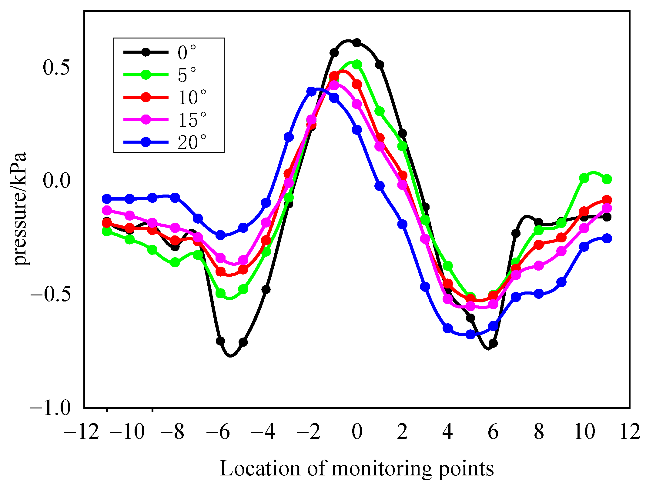
3.3. Flow Field Characterization for Target Attitude Recognition

Taking the bare hull model as an example, the target sails in the watershed at a uniform speed of 0.5 m/s, with attitude angles of 0°, 5°, 10°, 15°, and 20°, and collects the pressure signals from each monitoring point on the sideline sensing array at the moment of the 3rds, as shown in Figure 10.
From the figure, it can be seen that when the target is in different attitudes, the pressure distribution trend on the lateral sensing array is similar, and all of them show a distribution structure similar to “W”, in which the wave peaks appear in the head area and the wave valleys are in the back part of the torso, but this distribution structure is mainly due to the pressure distribution law of the robotic fish model itself. When the target model sails at 0° attitude, it can be seen that the pressure distribution on the positive and negative lateral lines shows better symmetry, with the wave peak appearing at the monitoring point S 0 and the wave trough at the monitoring points S 6 and S 6 . With a change in the target attitude, the pressure distribution on the positive and negative sidelines gradually becomes asymmetric, which is mainly manifested in three aspects: firstly, the wave peak position is gradually shifted to the direction of the negative sideline, and the wave peak position appears at the monitoring point S 3 when the deflection is 20°, for example; secondly, the deviation of the pressure values of the two wave valleys is gradually enlarged, which is mainly the pressure value on the negative sideline that increases with the increase in the deflection angle, as shown in Figure 11; and third, the wave peak value gradually decreases with the increase in the deflection angle.
According to the above change rule of the flow field signal with the target attitude, the distance of the peak appearance point offset from the center point can be selected as the positional eigenfactor S max S 0 , the ratio between the pressure difference between the two wave troughs and the wave peaks can be selected as the symmetry eigenfactor p min p + min / p max , the ratio between the two fluctuation amplitudes can be used as the amplitude eigenfactor p max p min / p max p + min , and the above three dimensionless eigenfactors can be used as the recognition features of the target attitude.

4. Recognition Result Analysis of Target Perception

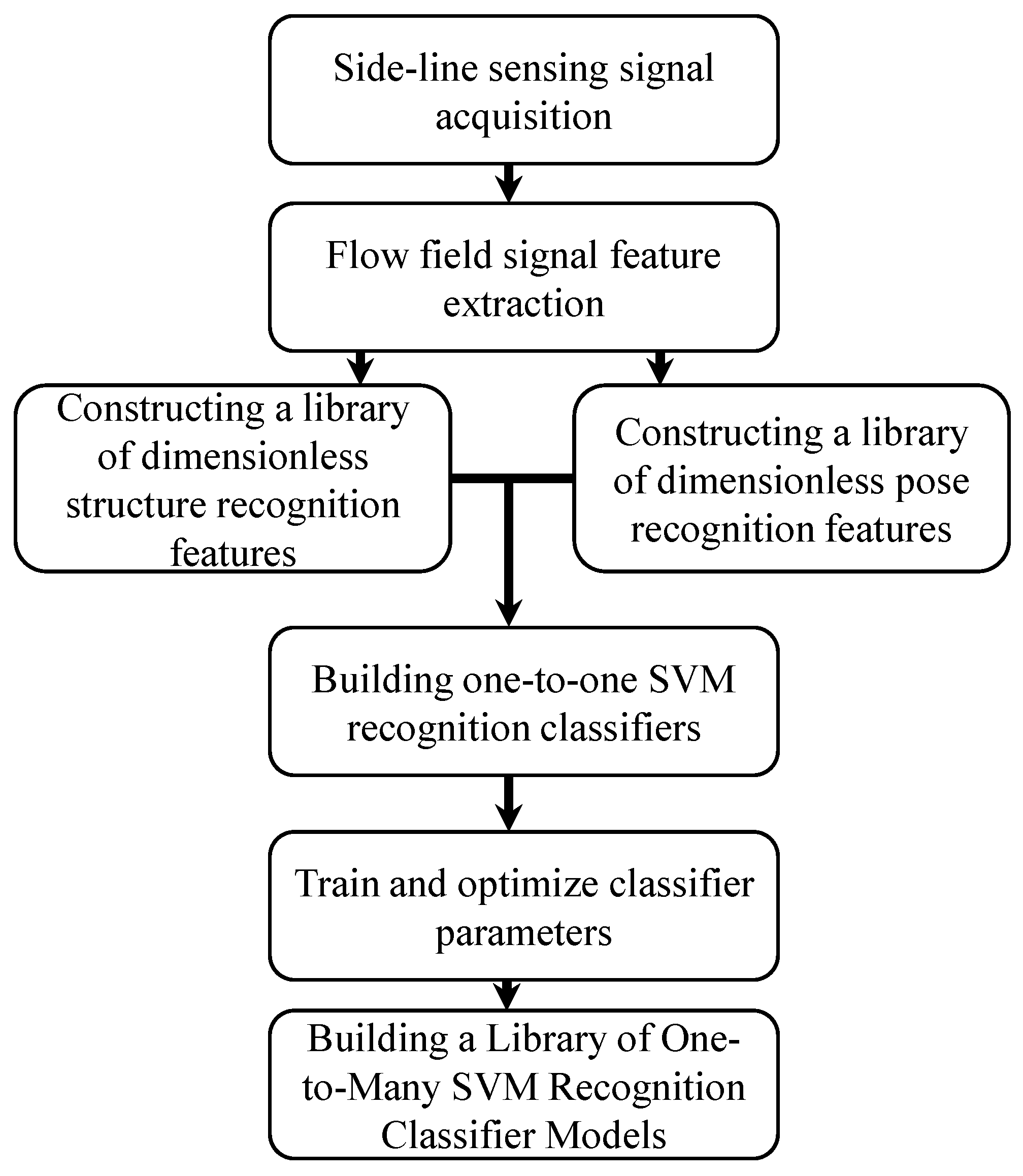
4.1. Model Construction of Target Recognition Classifiers

Target body recognition based on the flow field signal is a complex nonlinear problem, and the number of samples is limited, which belongs to a small-sample, low signal-to-noise ratio recognition classification problem, so the performance requirements for the recognition classifier are more stringent. SVM is a classification recognizer established based on statistical learning theory, and it can be effectively solved for the nonlinear target recognition classification problem by constructing the appropriate kernel function. In our previous research, the influences of linear kernel functions, polynomial kernel functions, and radial basis kernel functions on the identification results of this type of problem were compared and analyzed. The results show that polynomial kernel functions have better adaptability in processing underwater flow field information [13].
Therefore, in this paper, we will construct an SVM multi-classification model by combining multiple binary classification models, i.e., by constructing M one-to-one SVM classifiers, and then carry out the integration into a one-to-many SVM classifier model, adopt the voting strategy to calculate the classification function, and finally obtain the largest voting result that is the recognition result.
In the construction process of the SVM classifier, an eighth-order polynomial kernel function was adopted for inner product processing. In order to maximize the evaluation of the model’s generalization ability under limited data and reduce the risk of overfitting, the K-fold cross-validation and two-step optimization method were adopted to optimize the hyperparameters of the penalty factor C and kernel parameters g [26]. In the first optimization process, 5-fold cross-validation was adopted to conduct preliminary searches within the ranges of [2−6,26] and [2−10,210]. The second optimization was carried out for the output optimal solution combination C 1 , g 1 . The range of the second optimization was set as C 1 / 4 , 4 C 1 and g 1 / 4 , 4 g 1 , and 10-fold cross-validation was used. Finally, the optimal hyperparameter combination can be obtained, and the model construction process is shown in Figure 12.

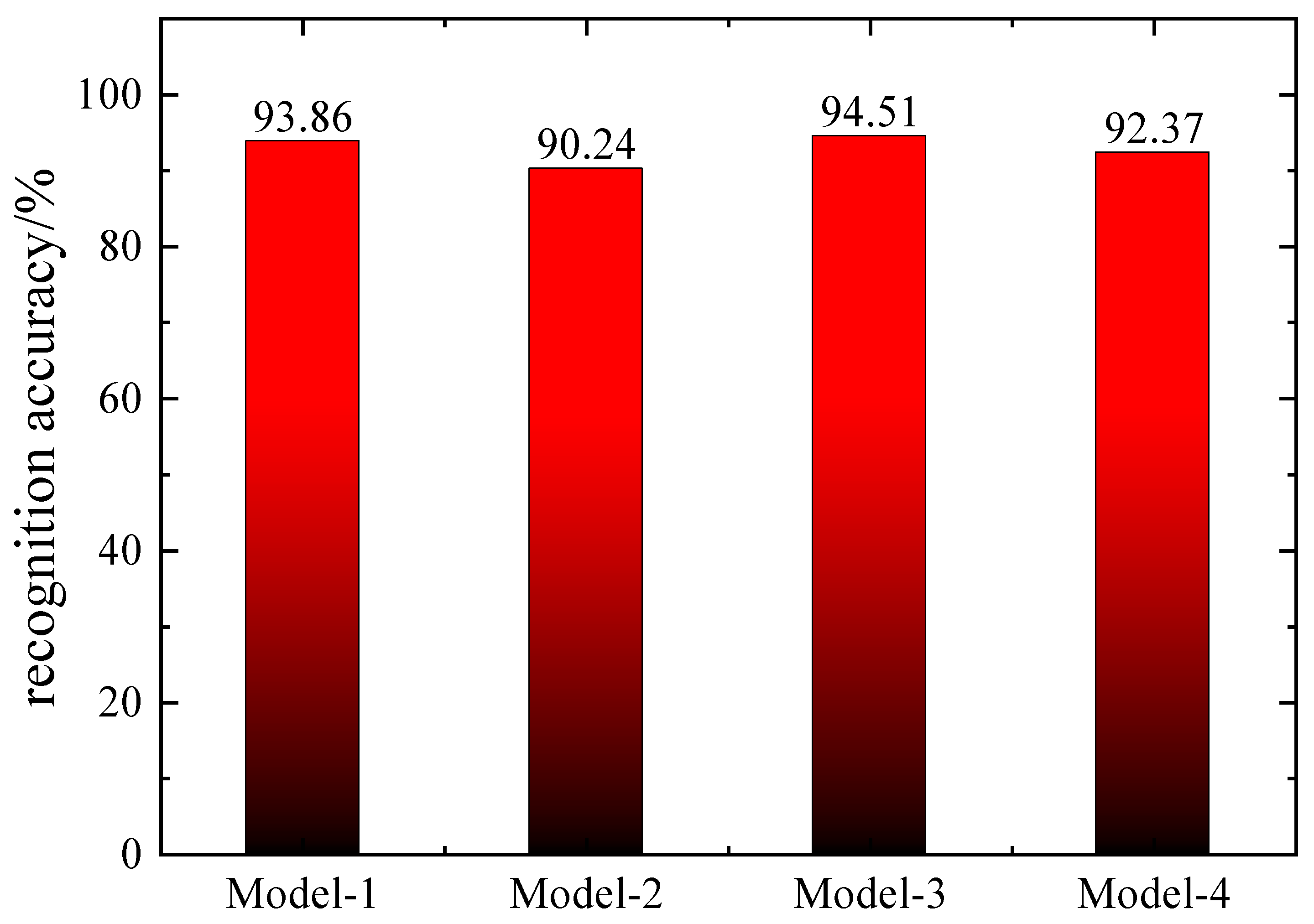
4.2. Analysis of Results of Target Structure Identification

Four structures of SUBOFF model target bodies were selected to navigate at a uniform speed in four environments with flow velocities of 0.5 m/s, 1.0 m/s, 1.5 m/s, and 2.0 m/s, and the pressure signals from 23 sensors on the sideline sensing arrays were collected for the time period of 0–3 s, which constituted a total of 368 groups of signal databases. In each group of signal curves, the characteristic wave peak value p m a x , wave trough value p m i n , wave peak appearance time t m a x , wave trough appearance time t m i n , and zero crossing time t z e r o of the pressure signal are extracted, and the dimensionless structural identification features are calculated, including the intensity characteristic factor p m a x / p m i n and the time characteristic factor   t z e r o / t m a x t m i n , which finally form a 368×2 dimensional feature database.
In the target type definition stage, only the difference in the target structure is considered, i.e., the flow field signals generated by the same model at different flow field velocities are defined as the same class, thus a total of one to four different type numbers are included to form a 368 × 1 dimensional type library. Two different types of feature data are selected at a time to form 184 sets of data, of which 161 sets are training data and 23 sets of data of the same structure at a certain flow velocity are used as test data to construct and optimize a one-to-one SVM recognition classifier, and a one-to-many SVM fusion model is finally formed by fusing the six SVM recognition classifiers formed in tandem.
In this paper, the pressure signals of four different structure models in the flow field environment with a flow velocity of 0.5 m/s were selected as validation data, the recognition classification was carried out according to the above steps, and all of them finally obtained more than 90% recognition accuracy, as shown in Figure 13, which proves that based on the bionic sidereal sensing of the flow field signals, the recognition of the target structure can be realized.

4.3. Analysis of the Results of Target Attitude Recognition

The SUBOFF bareboat model was selected as the target body, sailing at a uniform speed in four environments with flow velocities of 0.5 m/s, 1.0 m/s, 1.5 m/s, and 2.0 m/s. A set of pressure signals was collected on the sideline sensing array at intervals of 0.1 s within a time period of 1–3 s to constitute a total of 80 groups of signal data, each group of which consisted of the sensing signals of 23 sensors at the time. To form a pressure signal distribution curve, we extracted the wave peak value p m a x , negative sideline wave valley value p m i n , positive sideline wave valley value p + m i n , and the position of the wave peak s m a x , and calculated the dimensionless structural identification features, including the positional eigenfactor S m a x S 0 , symmetry eigenfactor p m i n p + m i n / p m a x , and magnitude eigenfactor p m a x p m i n / p m a x p + m i n , resulting in an 80 × 3-dimensional feature database.
In the target type definition stage, only the different target attitude angles are considered, i.e., the flow field signals generated by the same attitude angle under different flow field velocities are defined as the same class, thus a total of one to five different type numbers are included to form an 80 × 1-dimensional type library. The feature data of two different attitude angles are selected each time to form 40 sets of data, of which 36 sets are training data, while 4 sets of data with the same attitude angle at a certain moment are used as test data to construct and optimize the one-to-one SVM recognition classifier. In posture recognition, a total of 24 independent SVM recognition classifiers are formed, and the one-to-many SVM fusion model is finally formed by adding a vote-counting function to them.
In this paper, the pressure signals acquired by the SUBOFF bareboat model at five attitude angles of 0°, 5°, 10°, 15°, and 20° in four flow field environments at the second second are selected as the validation data, the recognition and classification are carried out according to the above steps, and the results of the target attitude recognition are basically the same as the law described above, as shown in Figure 14. More than 95% recognition accuracy can be obtained, which proves that the recognition of target attitude characteristics can be realized based on the bionic lateral line sensing of the flow field signal.

5. Conclusions and Outlook

In this paper, the SUBOFF model is used as the target source, and the lateral line sensing array is constructed based on the bionic robotic fish model. CFD numerical simulation is used to collect the pressure field signal as the input information for flow field sensing, and through the analysis of the time-domain and space-domain features of the input signal, the recognition classifier of the target features is constructed, which then realizes the perception of the target structural features and attitude features, and reveals the principle of the fish neural center. The principle of target feature resolution based on sideline sensing signals is revealed, and the following conclusions are obtained:
(1) Based on the pressure fluctuation signals sensed on the sideline array, extract the wave peak value p m a x , wave trough value p m i n , wave peak appearance time t m a x , wave trough appearance time t m i n , and zero crossing time t z e r o as signal fluctuation features, and compute the dimensionless intensity eigenfactor p m a x / p m i n and time eigenfactor t z e r o / t m a x t m i n as the structural identification features, which can effectively differentiate different target body structure types.
(2) Based on the pressure distribution signal sensed by the sideline array, the wave peak value p m a x , negative sideline wave valley value p m i n , positive sideline wave valley value p + m i n , and wave peak appearance location s m a x are extracted as the signal distribution features, and the dimensionless positional eigenfactor S m a x S 0 , the symmetric eigenfactor p m i n p + m i n / p m a x , and the amplitude eigenfactor   p m a x p m i n / p m a x p + m i n are as the identification features of attitude angle, which can effectively predict the attitude angle of the target.
(3) The SVM recognition classifier model based on a polynomial kernel function is used to form a one-to-many fused SVM recognition classifier by fusing multiple one-to-one SVMs, which can effectively recognize the structure type and attitude angle of the target body, in which the accuracies of recognition of the structure type are all greater than 90%, and the accuracies of prediction of recognition of the attitude angle are all greater than 85%.
The current study assumes that the flow field environment is a stable state and does not focus on the problem of recognizing the intention of the target during the transition of the target motion state, which is one of the most critical pieces of perceptual information in the trajectory tracking process. Therefore, future research needs to strengthen the theoretical and methodological study of bionic sidereal perception technology for dynamic target detection in complex environments, explore the intrinsic coupling mechanism between target motion state and flow field characteristics, and realize the prediction of target motion intention and real-time localization of position coordinates. Meanwhile, in subsequent work, we will set up a corresponding water pool towing experimental environment and verify the feasibility of underwater target recognition based on the characteristics of flow field signals by constructing a principle prototype model.

Author Contributions

Conceptualization, X.L. and H.X.; methodology, X.L.; software, H.X.; validation, H.W., P.S. and E.Y.; formal analysis, G.Z.; investigation, H.W.; resources, P.S.; data curation, E.Y.; writing—original draft preparation, H.X.; writing—review and editing, X.L.; visualization, G.Z.; supervision, X.L.; project administration, X.L.; funding acquisition, X.L. All authors have read and agreed to the published version of the manuscript.

Funding

The authors disclose receipt of the following financial support for the research, authorship, and/or publication of this article: This work was supported by the National Natural Science Foundation of China (62301360).

Data Availability Statement

The raw data supporting the conclusions of this article will be made available by the authors on request.

Conflicts of Interest

The authors declare no potential conflicts of interest with respect to the research, authorship, and/or publication of this article.

References

  1. Rashmi, S.N.; Rohit, A.; Domninc, S.; Kumar, A. Image mining application for underwater environment management: A review and research agenda. Int. J. Inf. Manag. Data Insights 2021, 1, 100023. [Google Scholar]
  2. Zhang, L.Y.; Li, C.Y.; Sun, H.F. Object detection/tracking toward underwater photographs by remotely operated vehicles (ROVs). Future Gener. Comput. Syst. 2022, 126, 163–168. [Google Scholar] [CrossRef]
  3. Wang, N.; Wang, Y.Y.; Meng, J.E. Review on deep learning techniques for marine object recognition: Architectures and algorithms. Control Eng. Pract. 2022, 118, 104458. [Google Scholar] [CrossRef]
  4. Bucci, A.; Zacchini, L.; Franchi, M.; Ridolfi, A.; Allotta, B. Comparison of feature detection and outlier removal strategies in a mono visual odometry algorithm for underwater navigation. Appl. Ocean Res. 2022, 118, 102961. [Google Scholar] [CrossRef]
  5. García-Vega, A.; Fuentes-Pérez, J.F.; Fukuda, S.; Kruusmaa, M.; Sanz-Ronda, F.J.; Tuhtan, J.A. Artificial lateral line for aquatic habitat modelling: An example for lefua echigonia. Ecol. Inform. 2021, 65, 101388. [Google Scholar] [CrossRef]
  6. Brian, M.M. Lateral line: From water waves to brain waves. Curr. Biol. 2021, 31, 344–347. [Google Scholar]
  7. Peloggia, J.; Münch, D.; Meneses-Giles, P.; Romero-Carvajal, A.; Lush, M.E.; Lawson, N.D.; McClain, M.; Pan, Y.A.; Piotrowski, T. Adaptive cell invasion maintains lateral line organ homeostasis in response to environmental changes. Dev. Cell 2021, 56, 1296–1312. [Google Scholar] [CrossRef]
  8. Ahrari, A.; Lei, H.; Sharif, M.A.; Deb, K.; Tan, X. Reliable underwater dipole source characterization in 3D space by an optimally designed artificial line system. Bioinspiration Biomim. 2017, 12, 036010. [Google Scholar] [CrossRef]
  9. Ashraf, S.; Gao, M.; Chen, Z.; Naeem, H.; Ahmed, T. CED-OR based opportunistic routing mechanism for underwater wireless sensor networks. Wirel. Pers. Commun. 2022, 125, 487–511. [Google Scholar] [CrossRef]
  10. Zhang, Y.; Zheng, X.D.; Ji, M.J.; Lin, X.; Qiu, J.; Liu, G.J. Orientation recognition of underwater translational target based on fish lateral line perception principle and deep learning. J. Mech. Eng. 2020, 56, 231–239. [Google Scholar]
  11. Tuhtan, J.A.; Fuentes-Perez, J.F.; Toming, G.; Schneider, M.; Schwarzenberger, R.; Schletterer, M.; Kruusmaa, M. Man-made flows from a fish’s perspective: Autonomous classification of turbulent fishway flows with field data collected using an artificial lateral line. Bioinspiration Biomim. 2018, 13, 046006. [Google Scholar] [CrossRef] [PubMed]
  12. Lin, X.H.; Wu, J.G.; Qin, Q. A novel obstacle localization method for an underwater robot based on the flow field. J. Mar. Sci. Eng. 2019, 7, 437. [Google Scholar] [CrossRef]
  13. Lin, X.H.; Wu, J.G.; Wang, X.M.; Zhang, M.G.; Liu, H.T. Research on underwater triangular interference source sensing method based on lateral line sensing mechanism. J. Mech. Eng. 2020, 56, 240–248. [Google Scholar]
  14. Lin, X.H.; Wu, J.G.; Qin, Q. Robust classification method for underwater targets using the chaotic features of the flow field. J. Mar. Sci. Eng. 2020, 8, 111. [Google Scholar] [CrossRef]
  15. Liu, G.; Wang, M.; Xu, L.; Incecik, A.; Sotelo, M.A.; Li, Z.; Li, W. A new bionic lateral line system applied to pitch motion parameters perception for autonomous underwater vehicles. Appl. Ocean Res. 2020, 99, 102142. [Google Scholar] [CrossRef]
  16. Wang, M.; Jin, B.; Liu, G.; Li, Z. The moving vibration source perception using bionic lateral line system and data-driven method. Ocean Eng. 2022, 247, 110463. [Google Scholar] [CrossRef]
  17. Li, Y.X.; Hu, Q.; Liu, Y.; Yang, Q. Optimized arrangement model and evaluation method of bionic lateral line detection array for underwater vehicles. J. Xi’an Jiaotong Univ. 2021, 55, 34–45. [Google Scholar]
  18. Ghommem, M.; Bourantas, G.; Wittek, A.; Miller, K.; Hajj, M.R. Hydrodynamic modeling and performance analysis of bio-inspired swimming. Ocean Eng. 2020, 197, 106897. [Google Scholar] [CrossRef]
  19. Zhang, X.; Shan, X.; Xie, T.; Miao, J.; Du, H.; Song, R. Harbor seal whisker inspired self-powered piezoelectric sensor for detecting the underwater flow angle of attack and velocity. Measurement 2021, 172, 108866. [Google Scholar] [CrossRef]
  20. Yanagitsuru, Y.R.; Akanyeti, O.; Liao, J.C. Head width influences flow sensing by the lateral line canal system in fishes. J. Exp. Biol. 2018, 221, 180877. [Google Scholar] [CrossRef]
  21. Zhai, Y.F.; Xiong, M.L.; Wang, C.; Xie, G.M. Progress of underwater bionic lateral line sensing. J. Underw. Unmanned Syst. 2023, 31, 50–67. [Google Scholar]
  22. Yang, Q.; Hu, Q.; Shan, L.; Jiang, G.; Yao, Y.; Tang, L.; Zhu, Z.; Aabloo, A. A Cavity-Type Pressure Sensor Array with High Anti-Disturbance Performance Inspired by Fish Lateral Line Canal. IEEE Sens. J. 2024, 24, 14050–14058. [Google Scholar] [CrossRef]
  23. Luo, R.; Li, C.; Wang, F. Underwater motion target recognition using artificial lateral line system and artificial neural network method. Ocean. Eng. 2024, 303, 117757. [Google Scholar] [CrossRef]
  24. Zhang, N.; Shen, H.C.; Yao, H.Z. Numerical simulation and validation of submarine resistance and flow field and numerical optimization of boat type. Ship Mech. 2005, 9, 13. [Google Scholar]
  25. Stern, F.; Wilson, R.V.; Coleman, H.W.; Paterson, E.G. Comprehensive Approach to Verification and Validation of CFD Simulations—Part 1: Methodology and Procedures. J. Fluids Eng. 2001, 123, 793–802. [Google Scholar] [CrossRef]
  26. Lin, X.H.; Wu, J.G.; Qin, Q.; Li, W.M. Research on target-sensing method of underwater robots based on the lateral line mechanism. J. Ship Mech. 2020, 24, 559–569. [Google Scholar]
Figure 1. Schematic structure of fish lateral line system.
Water 17 02006 g001
Figure 2. SUBOFF submarine fully attached 3D model with coordinate definition.
Water 17 02006 g002
Figure 3. CFD simulation computational domain and boundary conditions.
Water 17 02006 g003
Figure 4. Mesh division around AUV.
Water 17 02006 g004
Figure 5. Distribution curve of AUV surface pressure coefficient.
Water 17 02006 g005
Figure 6. Schematic diagram of the structure of the bionic lateral line sensing array.
Water 17 02006 g006
Figure 7. Schematic diagram of the structure of the target-aware model.
Water 17 02006 g007
Figure 8. Variation curve of sideline sensed pressure signals with time.
Water 17 02006 g008
Figure 9. Distribution of dimensionless flow field characteristics for different structural targets.
Water 17 02006 g009
Figure 10. Pressure signal distribution curve of sideline sensing array.
Water 17 02006 g010
Figure 11. Pressure difference distribution curves for sideline sensing arrays.
Water 17 02006 g011
Figure 12. Flowchart of the construction of the target perception recognition model.
Water 17 02006 g012
Figure 13. Target body structure feature recognition results.
Water 17 02006 g013
Figure 14. Target body attitude angle recognition results.
Water 17 02006 g014
Table 1. Grid independence analysis.
Grids i C d × 10 1 Convergence TypeRate of Change/%
Grid-14.02.962MC1.689
Grid-23.02.916MC1.375
Grid-32.02.873MC0.696
Grid-41.02.855MC0.004
Grid-50.52.848MC\
Table 2. Comparative data for submarine drag coefficient Cd.
Comparative ParametersExperimental GroupSimulation GroupRelative Error
C d 0.2860.2792.41%
Disclaimer/Publisher’s Note: The statements, opinions and data contained in all publications are solely those of the individual author(s) and contributor(s) and not of MDPI and/or the editor(s). MDPI and/or the editor(s) disclaim responsibility for any injury to people or property resulting from any ideas, methods, instructions or products referred to in the content.

