1. Introduction
In China, coal plays a dominant role in both energy production and consumption, and excessive resource development has given rise to many types of mine disasters, among which mine bed-separation water damage is a relatively new type of disaster in China in the last decade [
1]. Mining-induced stratum movement creates differential settlement, with the deformation magnitude showing a negative correlation to both layer thickness and compressive strength. Bed separation occurs when interfacial tensile stress exceeds the weak–strong rock interface strength [
2,
3,
4,
5,
6]. Bed separation is usually a storage space for liquid and gas, which can cause serious harm to mining activities, such as the 5.21 water inrush accident in the Ha zi Coal Mine of China in 2005, which caused five deaths [
7]. Grouting of bed separation to reduce settlement effectively prevents water inrush accidents [
8,
9]. Therefore, it is necessary to accurately identify and calculate the volume of the storage space of bed-separation layers formed in the mining process.
Coal mining operations induce a water-conducting fracture zone (WCFZ) [
10]. The formation of bed separation within the scope of the water-conducting fissure zone poses a significant challenge in establishing a closed water-filled space, thereby mitigating the risk of sudden water accidents. Conversely, when bed separation occurs above WCFZ, the hanging wall zone of bed separation expands progressively in response to working face advances (
Figure 1). Under negative pressure and gravity, groundwater rushes in, filling the bed-separation space. A sudden rupture of the protective layer may cause mine stratum water damage, resulting in severe personnel and property losses [
11,
12,
13].
The predominant methodologies for calculating bed-separation volume currently include the elastic thin-plate theory calculation method [
14,
15,
16,
17,
18,
19], the water volume segmentation method [
20], and the extensive well method [
21]. However, these methods neglect the effect of bed development on variations in bed-separation volume. During the development of the bed, when the rock strata are bent to a certain degree, they will be supported by the rock mass below. The development of the bed undergoes a transition from vertical to horizontal expansion [
22]. Existing calculation methods for the volume of bed-separation water do not consider the effect of different development forms of the bed at various stages.
In light of the inherent limitations of prevailing calculation methodologies, this study proposes a bed-separation layer discrimination criterion predicated on rock stratum bending deflection and a bed-separation spatial volume calculation method for varying development stages. The evolution of bed separation can be considered during coal extraction processes. Empirical field data and numerical simulation techniques have substantiated the research findings. The prevention and management of bed-separation water inrush can be significantly improved by this study’s findings, enhancing mine operational safety.
2. The Method for Determining the Position of the Bed Separation Is Based on the Flexible Thin-Plate Theory and SCCM
2.1. SCCM
After coal mining, the overburdened rock will lose its original state and begin to deform and break, and the rock strata will deform under the load from above and their own gravity [
23,
24]. Differential vertical deformation occurs in adjacent rock strata owing to their distinct mechanical characteristics. When the upper strata exhibit greater deflection than the underlying strata, it will settle with the lower rock strata as a rock form of synchronous settlement with the lower rock formation. During this phase, the response of overlying strata to mining-induced stresses is largely determined by the properties of the lower strata. Therefore, when analyzing the stress and deflection of the bed separation’s upper and lower rock plates, it is necessary to consider the influence of the internal forces and displacement changes in other rock plates on it, such as changes in load.
The traditional bed-separation identification method relies on composite beam theory, where the bed-separation location is determined by comparing the load on the underlying rock layer of a composite beam composed of
n + 1 rock layers with that of a composite beam made up of n rock layers undergoing synchronous deformation [
25,
26]. This approach overlooks the interactions between rock strata. He [
27] and others introduced the SCCM based on composite beam theory. This method considers the overlying rock strata above a coal seam as a composite beam and determines whether adjacent rock strata deform synchronously by calculating the deflection of this beam. However, the deflections calculated using SCCM do not accurately reflect the deformation characteristics of actual strata or bed-separation development. This study combines the deflections calculated from elastic thin-plate theory with SCCM to distinguish between bed-separation layers accurately.
The SCCM principle involves comparing the deflections of adjacent rock strata in the same layer and grouping adjacent rock strata whose upper rock strata have a more significant deflection than the lower rock strata into large rock stratum combinations. Each overburden stratum is analyzed independently, with self-weight bending representing the first deformation phase. A comparative analysis of inter-stratum deflections identifies adjacent layer combinations with bigger displacements in upper strata, which are then consolidated into a unified stratum combination. The bending state of each rock stratum combination formed by the combinations in the first stage, under the action of its weight, is the second stage. By comparing the deflections between the adjacent rock stratum combinations in the second stage, we identify the upper rock stratum combination with a more significant deflection than the adjoining rock stratum combination of the lower rock stratum combination, and group them into a more significant rock stratum combination. Each rock stratum combination formed by the combinations in Stage II bends under the action of its weight only, and the same goes for Stage III, and so on. The combinations are gradually performed in this way until no further combinations can be performed. It is believed that bed separation occurs between the adjacent rock stratum combinations of the subsequent stages, and that the curvature of the upper rock stratum combination is smaller than that of the lower rock stratum combination.
2.2. Calculation of the Deflection of Rock Strata Based on the Theory of Elastic Thin Plates
During coal mining, the bending behavior of overburden rock exhibits a three-dimensional stress state, with stratum thickness corresponding to thin-plate structural classification (1/100~1/80 ≦ h/a ≦ 1/8~1/5 where h is the thickness of the rock strata and a is the minimum characteristic dimension of the rock strata). Consequently, the bending deformation of the rock strata can be simplified to a thin-plate bending model. Furthermore, given that the bending deflection of the rock strata is considerably smaller than their thickness, and the film stress generated on the plate surface is significantly less than the bending stress of the rock strata, the thin-plate bending problem can be addressed through the small deflection problem.
If there are
m rock strata in the upper part of the goaf, these rock strata are considered
m-th elastic thin plates with uniform, continuous, isotropic, and linear elastic properties (
Figure 2). The thickness, gravitational density, elastic modulus, cross-sectional moment of inertia, and the self-weight load of each layer are
hi,
γi,
Ei,
Ii, and
σi, respectively. In addition, these thin plates should also meet the following conditions:
- (1)
The boundary of the thin plate is fixed on all sides, and the bottom of the rock plate within WCFZ is treated as an elastic foundation.
- (2)
The equivalent thin-plate thickness is determined by averaging individual stratum thicknesses across the rock layer sequence.
- (3)
The thin-plate deflection computation adheres to Kirchhoff’s assumptions: ① normal strain εz perpendicular to the midplane remains constant through the thickness, with ∂w/∂z = 0; ② all mid-surface points of the thin plate remain stationary along the x and y axes.
The stress state of a rock microelement taken from the rock strata is shown in
Figure 3. According to the stress analysis of the microelement based on elasticity theory, the microelement mechanical Equation (1), geometric Equations (2) and (3), and physical differential Equation (4) of the rock microelement are as follows:
Here,
u,
v, and
w are the displacements in the
x,
y, and
z directions, m;
σx,
σy, and
σz are the principal stresses in the
x,
y, and
z directions, MPa;
εx,
εy, and
εz are the strains in the
x,
y, and
z directions;
τxy,
τxz, and
τyz are the shear stresses in the
x,
y, and
z directions, MPa;
γxy,
γxz, and
γyz are the shear strains in the
x,
y, and
z directions;
µ is Poisson’s ratio; and
E is the elastic modulus, MPa.
The bending behavior of thin plates subjected to normal surface loads is governed by the following differential equation:
where
is the bending stiffness of a thin plate.
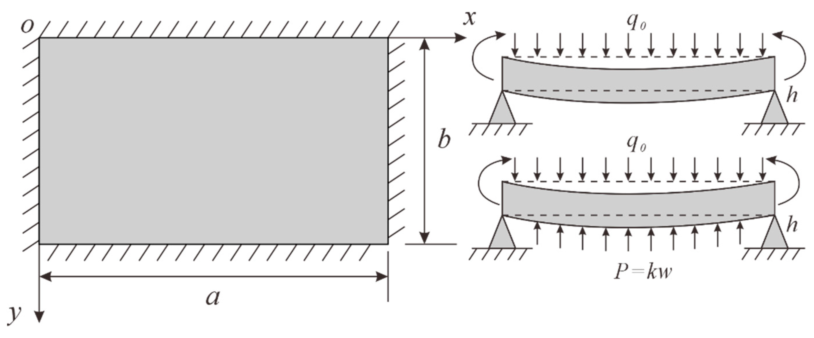
It is assumed that the inclined length of the working face is
b1 after a distance
L from the coal seam entry and that the boundary conditions of the upper and lower rock strata at the bed separation are fixed on all sides (
Figure 4). The length and width of each overlying rock stratum are to be calculated according to the following formula:
where
a is the length of the plate along the direction of the coal seam, and
b is the length of the plate along the dip of the coal seam.
Based on the minimum potential energy principle, the equation for the deflection
w of the thin plate at the first break can be obtained [
28]:
3. Calculation of Bed-Separation Volume Based on Elastic Thin-Plate Theory and Developmental Morphology of Bed Separation
Among multiple bed-separation spaces, structural instability first develops in the vertically lowest bed-separation interface, and the “bed separation” studied next is the first bed separation above the WCFZ. The developmental spatial volume of the bed separation is expected to be critical for bed-separation grouting control and an early warning of water inrush volumes. Chen [
29] and Fan [
30] obtained that the development process of bed separation is divided into three stages through the on-site testing (
Figure 5) of Yingpanhao Coal Mine, which are the vertical development stage, horizontal development stage, and the developmental closure stage. The bed separation’s expansion is mainly vertical when the coal seam is mined early. After advancing a certain distance, the bending deflection of lower strata attains the maximum allowable displacement within the WCFZ. The bed separation begins to expand horizontally. Therefore, the deflection of the rock stratum group at the stage of the bed separation’s horizontal development is related to the maximum free-moving space of the rock strata (
Figure 6). The most commonly used method for calculating the bed-separation space is to utilize elastic thin-plate theory for the three-dimensional spatial integration of the upper and lower rock plates. The calculation disregards the effect of bed separation’s developmental phase on its volume.
4. The Dynamically Developed Volume of Bed Separation
As the coal seam is mined, the rock layers in the goaf are broken, compacted, and settled; assuming that the number of rock strata in WCFZ is
j, the free movement space can be calculated using the following [
24]:
where
hf is the free space, m;
M is the thickness of the coal seam, m;
fj is the expansion coefficient of the
jth strata; and
hj is the thickness of the
jth strata, m.
As the lower rock strata deform and contact underlying layers, the bed-separation space transitions from vertical to horizontal expansion until upper strata fracture, leading to separation space closure failure. Therefore, the bed separation’s developmental phase must be assessed to calculate its volumetric evolution during mining (
Figure 7). If the thin plate’s deflection is below
hf, the bed separation is in the vertical development Stage I. The following formula can be used to calculate the volume of bed-separation space
V1:
where
wb is the deflection of the lower strata,
wt is the deflection of the upper rock strata, and
Ω is the area of the bed-separation region.
Horizontal expansion initiates when the lower strata’s ultimate deflection attains
hf, with WCFZ providing support to underlying rock groups. The rock strata inside WCFZ can be regarded as a model of Winkle’s elastic foundation, and at this time, the equation of deflection of the thin plate is as follows [
31]:
where
wk is the deflection of the rock strata below the bed separation in the support region, and
k is the Winkler elastic foundation coefficient, which can be determined by the following formula method [
32]:
where
hj is the thickness of the
jth rock strata, m, and
Ej is the modulus of elasticity of the
jth rock strata, MPa.
When the lower rock strata bottom out, the vertical bending deflection
ws shall be the sum of
hf and
wk:
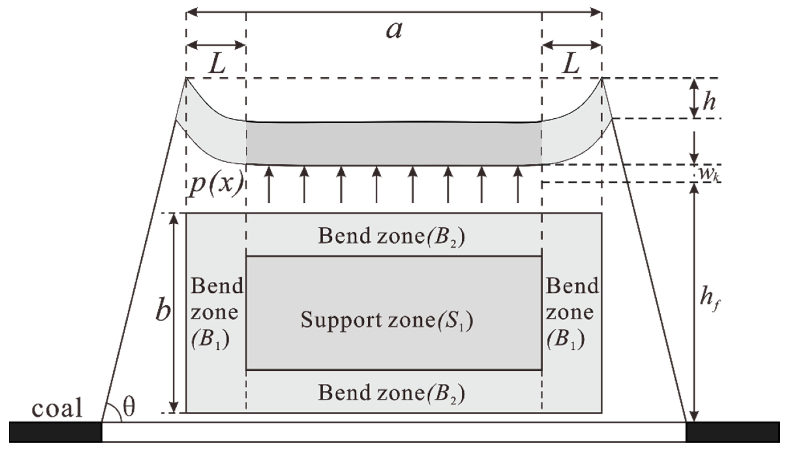
During horizontal expansion, the bed-separation volume equals the supported central region’s cumulative volume in rock strata,
S1, and the volumes of the surrounding overhanging rock strata,
B1 and
B2 (
Figure 7), which can be calculated using the following equation:
where
VB1,
VB2, and
Vs are the volumes of the corresponding regions in
Figure 7, respectively.
In summary,
Figure 8 shows the calculation process.
5. Water Inrush Case Validation
5.1. Overview of the Study Area
The study area is a 21301 working face in the 21 disk area of Cui mu Coal Mine, Shaanxi Province, China. The geographic location of the study area is shown in
Figure 9, and the surface is mainly loess, beam loess, and gully area;
Table 1 and
Table 2 present the stratigraphic distribution and mechanical properties of the study area. The primary mined coal seam is No. 3 coal in Jurassic Yanan Formation (J
2y), averaging 10 m in thickness. The 21301 working face recorded twelve water inrushes during mining, and water inflow surged abruptly to 60,059 m
3 at a 500 m advancement, posing severe threats to mine safety (
Figure 10). This study examines the water inrush incident at Cui mu Mine’s 21301 working face as a representative case. The calculation of water inrush in bed separation is carried out by using the bed-separation spatial calculation method based on developmental morphology, and the result is compared with the actual water inrush in the 21301 working face and the results of elastic thin-plate theory to validate the feasibility of this method.
The Luohe Formation can be divided into upper and lower sections. The upper section is dominated by feldspathic quartz sandstones, with medium and fine-grained structures and strong water-rich and hydraulic connections; the lower section is conglomerate-bearing sandstones, with local distribution, and is dominated by muddy cement, with more developed local fissures; and the Yijun Formation is exposed only in individual boreholes, with a small thickness, and with the lithology of grayish-purple conglomerate. The Anding Formation (J2a) is located under the Yijun Formation, and its lithology is mainly gray-purple and dark-purple mudstone, sandy mudstone, and siltstone.
5.2. Height of WCFZ
Forming bed separation requires “closed bed-separation space” and “continuous aquifer recharge”. Bed separations within the WCFZ rapidly lose integrity during mining, preventing water accumulation. The saturated compressive strength of the rock is 4.00–23.9 MPa within a range of 50 m of the top plate of the coal bed. The inclination angle of the coal bed is 3–6°, which belongs to the near horizontal coal bed, and the average thickness of No. 3 coal mining is 10 m. Based on the WCFZ height empirical formula, its maximum developmental height reaches 145.95 m.
5.3. Bed-Separation Layer Identification
Based on the stratigraphic properties of the study area, the stratum deflection at a mining advance of 300 m was calculated using the elastic thin-plate theory, as shown in
Table 3.
The identification process is detailed in
Table 4.
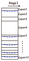
Stage Ⅰ: The deflection w0 of the rock strata above the WCFZ is calculated under its weight q0.
Stage II: Starting from the surface loess layer, rock strata with more significant deflections than their underlying layers are merged. For example, in Stage I, layer 1 and layer 2 deflections under their weights are 0.107 mm and 0.0776 mm, respectively. Since wl1 > wl2, layers 1 and 2 are combined into a single rock strata, which is designated as layer 1 in Stage II. The load on this combined strata is the sum of the loads on layers 1 and 2 in Stage I. This process continues, merging upper rock slabs with more significant deflections than those below them, resulting in the first set of combined rock stratum deflections w2.
Stage III: The merging process continues for the rock stratum combinations identified in Stage II until the deflections increase progressively from the surface to the top of the WCFZ. Bed-separation cavities will develop between adjacent rock stratum combinations.
The identification results show that bed-separation cavities are likely to develop between the following rock strata in the overlying formations of the 21301 working face: layer 2 (43.9 m, sandy mudstone), layer 4 (114.47 m, thick coarse sandstone), layer 6 (37 m, coarse sandstone), layer 8 (27.90 m, conglomerate), layer 9 (12.1 m, medium-grained sandstone), and their respective underlying rock stratum combinations. The bed separation primarily occurs within the Cretaceous rock layers and between the Luohe Formation and Anding Formation at the base of the Cretaceous system. These findings align with those of Qiao et al. [
33].
5.4. Bed-Separation Volume Calculation
The thin plate’s central point (a/2, b/2) is selected as the calculation point. The maximum deflections of the bed separation are calculated during coal seam mining. The free-space height,
hf, is 1.82 m (
Table 5). The bending deflections of rock strata during coal mining are shown in
Figure 11.
The bed separation remains unexpanded before the working face advances 100 m. With advancing extraction, both overlying and underlying strata exhibit progressive deflection, where lower strata deform faster than upper layers. During this stage, the bed separation primarily expands vertically. At 225.42 m of mining progress, lower stratum deflection coincides with the free displacement space height. At this point, the rocks within the WCFZ support the lower rock strata, transitioning the bed separation into a lateral expansion phase. Once the bed-separation cavity forms, the overlying aquifer’s water resources rapidly accumulate into the cavity due to hydrostatic pressure and negative pressure suction. The timing of bed-separation development and water accumulation is synchronous. Therefore, the developed bed-separation volume can be equivalent to the water lost from the Cretaceous aquifer.
Figure 12 compares calculated water inflow volumes in bed-separation voids at various mining stages with elastic thin-plate theory predictions. Compared to thin-plate theory’s low predictions, the morphological analysis method demonstrates better accuracy in matching actual inflow volumes. When the mining advance reaches 500 m, the calculated volume of the bed-separation cavity using the morphological development method is 50,586.6 m
3, representing 84.23% of the actual water inrush volume recorded in the mine. This value is less than the actual water inrush volume. An analysis suggests that the water inrush lasted nearly 9 days, during which the bed-separation cavity continuously received water from the overlying aquifer. Additionally, the actual water inrush volume includes the expected roof water inflow of the mine (about 54 m
3). Therefore, the bed-separation volume (and associated water volume) calculated based on morphological development is inherently smaller than the actual water inrush volume. In practical applications, it is essential to consider the continuous replenishment from the overlying aquifer and the mine’s expected water inflow when interpreting these calculation results.
To ensure model reliability, we performed Monte Carlo simulations combined with field-measured data, generating random samples for key parameters (elastic modulus E, Poisson’s ratio μ, and stratum thickness h). Using 10,000 simulations, we statistically analyzed the distribution characteristics of predicted bed separation. The calculated mean separation volume of the model is 50,605.85 m3, with a coefficient of variation (CV) of 7%. The low CV value (7% < 15%) indicates that the model is stable and highly reliable. The influence of these three parameters on the volume of bed separation is negatively correlated, and the influence of the three parameters on the results is E > h > μ.
5.5. Numerical Simulation Verification
The CDEM (Continuum–Discontinuum Element Method) is an explicit dynamic numerical analysis method that couples finite elements and discrete elements. The CDEM numerical framework incorporates dual components: material blocks represented by finite element assemblies capturing continuum behavior, and interfaces modeling discontinuities. The real interface is used to represent the material’s interface, faults, and joints. The virtual interface serves two purposes: one is to connect two blocks for mechanical information transfer, and the other is to act as a potential path for explicit crack propagation, allowing cracks to propagate along any virtual interface.
Figure 13 presents the schematic diagram of the numerical model using the CDEM, which includes eight blocks. Among them, two are made up of multiple triangular elements, while the remaining six consist of a single triangular element each. The real interface is marked by red lines, and black lines indicate the virtual interface.
A numerical model was created based on the actual strata (
Figure 14). The model dimensions are 700 m × 400 m × 259 m and contain 316,800 hexahedral elements. Different colors represent stratum of different lithologies. Without considering groundwater and geological structure, the model is combined with rock strata and divided into structural planes within the rock strata to form block units. The research focuses on the strata above the roof of the WCFZ. To improve computational efficiency, the overlying strata are applied as an equivalent uniform load on the model surface. Boundary conditions are set on the sides and bottom, with horizontal displacement constrained at the side boundaries, and the vertical and horizontal displacements of the bottom boundary are fixed. The Mohr–Coulomb constitutive model is selected for the block of the model, and the Mohr–Coulomb constitutive model of strain softening is selected for the contact surface. A 100 m protective coal pillar surrounds the working face to reduce boundary interference, adopting 10 m excavation increments.
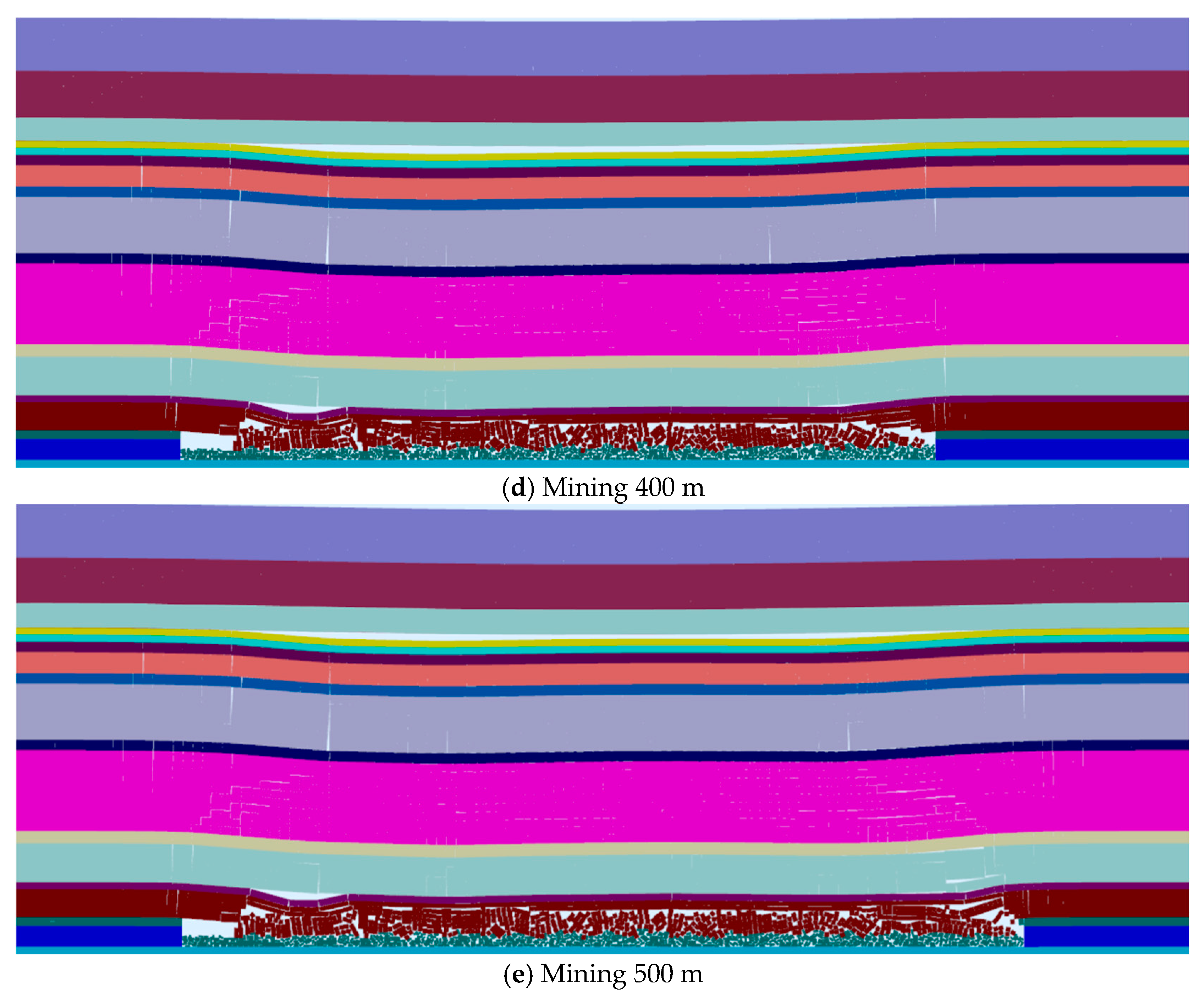
Figure 15 shows the roof stratum deformation during the mining process. The excavation of the coal seam disrupts the original stress balance, causing the immediate roof of coarse sandstone to collapse. When the working face advances to 200 m, the working face is in the square stage, and the roof rock stratum has obvious subsidence. There are obvious mining cracks in the stratum, forming WCFZ. At the same time, the upper coarse sandstone and the lower mudstone are pulled apart to form the separation space, the bed separation is in the vertical expansion stage, and the maximum deflection difference is about 1.92 m. When the working face advances to 300 m, it enters the horizontal expansion stage, which aligns with the numerical model’s results. As the working face of mining continues, the separation space further expands horizontally. The maximum volume of the bed separation, calculated by integrating the vertical displacement difference between the upper and lower rock layers, reaches 54,335.63 m
3 when the working face advances to 500 m, with a numerical calculation error of approximately 7.4%. Therefore, through the verification of CDEM numerical simulation, ISCCM can accurately calculate the volume of the separation space after mining the working face.
5.6. Limitations of Elastic Thin-Plate Theory for Water Inrush Prediction
Using composite beam principles, deflections of bed-separation bounding strata are determined and integrated to derive separation void volumes. In contrast, the improved SCCM identifies bed-separation locations by considering the strata as a combination of rock strata that move in concert, aligning more closely with the actual movement patterns observed in geological formations.
As shown in
Figure 12, after a mining advance of over 200 m, the volume of bed-separation cavities calculated using elastic thin-plate theory exhibits a linear trend. It is significantly lower than the results obtained from morphological development calculations. To investigate the reasons for this discrepancy, we plotted the deflection curves of the underlying rock strata at different stages of mining advances, as shown in
Figure 16. With increasing mining advances, the bending deflection in the mined-out area initially increases and then decreases. Moreover, the more significant the mining advance, the larger the reduction in bending deflection. This pattern does not match the settlement behavior typically observed in mined-out areas. Additionally, once a certain distance of coal seam extraction has been reached, the maximum bending deflection of the rock strata changes only slightly, indicating a “saturation” effect in the central region’s maximum deflection value according to thin-plate theory.
These factors lead to a notable underestimation of the bed-separation space when applying elastic thin-plate theory, with the error increasing as the mining advance grows. Consequently, using traditional elastic thin-plate theory to estimate the volume of bed-separation cavities to predict water inrush can result in severe water hazard accidents due to the significant underestimation of potential water volumes.
6. Conclusions
This study addresses the emerging issue of bed-separation water hazards in coal resource development in China, proposing a method for identifying bed-separation locations based on rock stratum bending deflections and a spatial volume calculation model that considers the stages of bed-separation development. Integrating improvements into the SCCM with elastic thin-plate theory offers more accurate predictions of bed-separation positions and associated water accumulation volumes, thereby providing robust technical support for safe and efficient mining operations. Through case study analysis at the 21301 working face of Cui mu Coal Mine, our findings demonstrate that the proposed methodology combining rock stratum bending deflection-based identification and spatial volume calculations exhibits higher accuracy and reliability in predicting bed-separation development and water inrush risks. Specifically, the following were found:
(1) Influence of bed-separation development morphology on water accumulation. Research indicates that variations in bed-separation morphology significantly impact water accumulation volumes. Traditional calculation methods may introduce substantial errors, particularly after long-distance coal extraction. Therefore, accounting for the effects of different developmental stages of bed separation is crucial for enhancing early warning capabilities and improving control measures against bed-separation water hazards.
(2) Accuracy of bed-separation space volume calculation. The integrated approach, incorporating elastic plate theory and separation morphology, accounts for deformation behaviors of rock strata and the developmental phases of bed separation. This approach enhances the accuracy of bed-separation space volume calculations, providing a more realistic reflection of actual bed-separation development. Consequently, it can be effectively applied to grouting prevention measures and water inrush volume warnings, offering improved reliability.
(3) Effectiveness of field validation. A case study analysis of the 21301 working face at Cui mu Coal Mine demonstrates the effectiveness of the proposed method in identifying bed-separation locations. Utilizing the morphological development-based calculation method, this approach accurately predicted the water inrush volumes from bed separation. Compared to traditional elastic thin-plate theory calculations, the proposed method yields predictions closer to actual water inrush volumes (calculating the maximum water inrush accounts for 84.23% of the actual water inflow), especially in capturing the trend of sudden increases in water inrush.
In summary, the method proposed in this study addresses the limitations of existing approaches for calculating bed-separation cavities, offering a more scientifically robust and practical means of predicting bed-separation development. This advancement enhances early warning capabilities for the bed separation of water hazards and provides critical technical support for ensuring safe and efficient mining operations. However, since the model regards the formation as a uniform plate model, when the rock layer is not nearly horizontal and is affected by faults, folds, and other structures, the accuracy of the model calculation will be affected. In the future, the dynamic change law of the development morphology and volume of the bed separation under the influence of different structural planes, such as faults and folds, should be considered.
Author Contributions
Conceptualization, D.L.; methodology, W.C.; software, D.L. and Q.W.; validation, D.L. and J.Y.; investigation, D.L.; resources, W.L.; data curation, Q.W.; writing—original draft preparation, D.L.; writing—review and editing, D.L. All authors have read and agreed to the published version of the manuscript.
Funding
This research was funded by the National Natural Science Foundation of China (No. 42372316), and the Graduate Innovation Program of China University of Mining and Technology (No. 2023WLKXJ006).
Data Availability Statement
Data are contained within the article.
Acknowledgments
The authors express their gratitude to everyone who provided assistance with the present study.
Conflicts of Interest
The authors declare no conflicts of interest.
References
- Gui, H.; Lin, M. Types of Water Hazards in China Coalmines and Regional Characteristics. Nat. Hazards 2016, 84, 1501–1512. [Google Scholar] [CrossRef]
- Jayanthu, S.; Singh, T.N.; Singh, D.P. Stress Distribution during Extraction of Pillars in a Thick Coal Seam. Rock Mech. Rock Eng. 2004, 37, 171–192. [Google Scholar] [CrossRef]
- Jiránková, E.; Petroš, V.; Šancer, J. The Assessment of Stress in an Exploited Rock Mass Based on the Disturbance of the Rigid Overlying Strata. Int. J. Rock Mech. Min. Sci. 2012, 50, 77–82. [Google Scholar] [CrossRef]
- Guo, H.; Yuan, L.; Shen, B.; Qu, Q.; Xue, J. Mining-Induced Strata Stress Changes, Fractures and Gas Flow Dynamics in Multi-Seam Longwall Mining. Int. J. Rock Mech. Min. Sci. 2012, 54, 129–139. [Google Scholar] [CrossRef]
- Wang, H.; Jiang, Y.; Zhao, Y.; Zhu, J.; Liu, S. Numerical Investigation of the Dynamic Mechanical State of a Coal Pillar during Longwall Mining Panel Extraction. Rock Mech. Rock Eng. 2013, 46, 1211–1221. [Google Scholar] [CrossRef]
- Jiang, B.; Wang, L.; Lu, Y.; Sun, X.; Jin, G. Ground Pressure and Overlying Strata Structure for a Repeated Mining Face of Residual Coal after Room and Pillar Mining. Int. J. Min. Sci. Technol. 2016, 26, 645–652. [Google Scholar] [CrossRef]
- Huang, W.P.; Li, C.; Zhang, L.W.; Yuan, Q.; Zheng, Y.S.; Liu, Y. In Situ Identification of Water-Permeable Fractured Zone in Overlying Composite Strata. Int. J. Rock Mech. Min. Sci. 2018, 105, 85–97. [Google Scholar] [CrossRef]
- Xuan, D.; Xu, J.; Wang, B.; Teng, H. Borehole Investigation of the Effectiveness of Grout Injection Technology on Coal Mine Subsidence Control. Rock Mech. Rock Eng. 2015, 48, 2435–2445. [Google Scholar] [CrossRef]
- Xuan, D.; Xu, J. Grout Injection into Bed Separation to Control Surface Subsidence during Longwall Mining under Villages: Case Study of Liudian Coal Mine, China. Nat. Hazards 2014, 73, 883–906. [Google Scholar] [CrossRef]
- Peng, S.S. Coal Mine Ground Control. Eng. Geol. 1981, 17, 76–77. [Google Scholar] [CrossRef]
- Wei, Q.; Wang, Z.; Li, W.; Lu, Y.; Li, L.; Huang, Y.; He, J.; Li, X.; Zhao, S.; Liu, M. Formation Mechanism, Disaster-Causing Mechanism and Prevention Technology of Roof Bed Separation Water Disaster in Coal Mine. J. China Coal Soc. 2021, 46, 507–522. Available online: https://www.mtxb.com.cn/en/article/Y2021/I2/507 (accessed on 18 January 2025).
- Gui, H.; Lin, M.; Song, X. Identification and Application of Roof Bed Separation (Water) in Coal Mines. Mine Water Environ. 2018, 37, 376–384. [Google Scholar] [CrossRef]
- Lu, Q.; Li, X.; Li, W.; Chen, W.; Li, L.; Liu, S. Risk Evaluation of Bed-Separation Water Inrush: A Case Study in the Yangliu Coal Mine, China. Mine Water Environ. 2018, 37, 288–299. [Google Scholar] [CrossRef]
- Wu, L.; Bai, H.; Ma, D. Prediction and Prevention of Water Inrush Hazards from Bed Separation Space. Mine Water Environ. 2021, 40, 657–670. [Google Scholar] [CrossRef]
- Xue, J.; Wang, H.; Zhou, W.; Ren, B.; Duan, C.; Deng, D. Experimental Research on Overlying Strata Movement and Fracture Evolution in Pillarless Stress-Relief Mining. Int. J. Coal Sci. Technol. 2015, 2, 38–45. [Google Scholar] [CrossRef]
- Jiang, J.; Xu, B. Study on the Development Laws of Bed-Separation under the Hard-Thick Magmatic Rock and Its Fracture Disaster-Causing Mechanism. Geotech. Geol. Eng. 2018, 36, 1525–1543. [Google Scholar] [CrossRef]
- Mehmood, E.; Rashid, I.; Ahmed, F.; Farooq, K.; Tufail, A.; Ebid, A.M. Hydrogeotechnical Predictive Approach for Rockfall Mountain Hazard Using Elastic Modulus and Peak Shear Stress at Soil–Rock Interface in Dry and Wet Phases at KKH Pakistan. Sustainability 2022, 14, 16740. [Google Scholar] [CrossRef]
- Li, Z.-Q.; Nie, L.; Xue, Y.; Li, W.; Fan, K. Model Testing on the Processes, Characteristics, and Mechanism of Water Inrush Induced by Karst Caves Ahead and alongside a Tunnel. Rock Mech. Rock Eng. 2025, 58, 5363–5380. [Google Scholar] [CrossRef]
- Nie, L.; Deng, Z.; Li, Z.-Q.; Song, Z.; Dong, S. Characterizing Water-Bearing Structure Ahead of Tunnel Using Full-Decay Induced Polarization Based on the Fuzzy C-Means Clustering Method. Tunn. Undergr. Space Technol. 2025, 155, 106159. [Google Scholar] [CrossRef]
- Xu, J.; Zhou, Y.; Pu, Z.; Pang, S. Calculation method of separated water accumulation in the process of separated water inrush and its forecast:Taking the water inrush at 1304 working face of Zhaoxian Coal Mine in Shaanxi Province as an example. J. China Coal Soc. 2022, 47, 3083–3090. [Google Scholar]
- Jiang, C. Mechanism and Prevention of Water Inrush from Higher Separated Spaces in Overlying Strata Under Excavation of Extremely Thick Coal Seams. Master’s Thesis, China University of Mining and Technology, Xuzhou, China, 2020. [Google Scholar]
- Xu, B.; Xu, W.; Zhang, Y. Experimental Study on the Characteristics of Overlying Rock Movement in Mining Area. Geotech. Geol. Eng. 2024, 42, 1779–1791. [Google Scholar] [CrossRef]
- Wang, H.; Xue, S.; Jiang, Y.; Deng, D.; Shi, S.; Zhang, D. Field Investigation of a Roof Fall Accident and Large Roadway Deformation under Geologically Complex Conditions in an Underground Coal Mine. Rock Mech. Rock Eng. 2018, 51, 1863–1883. [Google Scholar] [CrossRef]
- Ju, J.; Xu, J. Surface Stepped Subsidence Related to Top-Coal Caving Longwall Mining of Extremely Thick Coal Seam under Shallow Cover. Int. J. Rock Mech. Min. Sci. 2015, 78, 27–35. [Google Scholar] [CrossRef]
- Tan, Y.L.; Yu, F.H.; Chen, L. A New Approach for Predicting Bedding Separation of Roof Strata in Underground Coalmines. Int. J. Rock Mech. Min. Sci. 2013, 61, 183–188. [Google Scholar] [CrossRef]
- Fan, K.; Li, W.; Wang, Q.; Liu, S.; Xue, S.; Xie, C.; Wang, Z. Formation Mechanism and Prediction Method of Water Inrush from Separated Layers within Coal Seam Mining: A Case Study in the Shilawusu Mining Area, China. Eng. Fail. Anal. 2019, 103, 158–172. [Google Scholar] [CrossRef]
- He, J.-H.; Li, W.; Liu, Y.; Yang, Z.; Liu, S.-L.; Li, L.-F. An Improved Method for Determining the Position of Overlying Separated Strata in Mining. Eng. Fail. Anal. 2018, 83, 17–29. [Google Scholar] [CrossRef]
- Li, X. Study on the Inrush Mechanism of the Water in Bed Separation due to Repeated Coal Mining under Hard Rock. Ph.D. Thesis, China University of Mining and Technology, Xuzhou, China, 2011. [Google Scholar]
- Chen, W.; Li, W.; He, J.; Qiao, W.; Wang, Q.; Yang, Y. Impact of Mining-Induced Bed Separation Spaces on a Cretaceous Aquifer: A Case Study of the Yingpanhao Coal Mine, Ordos Basin, China. Hydrogeol. J. 2022, 30, 691–706. [Google Scholar] [CrossRef]
- Fan, K.; He, J.; Li, W.; Chen, W. Dynamic Evolution and Identification of Bed Separation in Overburden during Coal Mining. Rock Mech. Rock Eng. 2022, 55, 4015–4030. [Google Scholar] [CrossRef]
- Chen, W. Bed separation Dynamic Development and Response Mechanism of Extra-thick Cretaceous Aquifer Induced by Coal Mining. Ph.D. Thesis, China University of Mining and Technology, Xuzhou, China, 2022. [Google Scholar]
- Fan, K. Spatial and Temporal Evolution Model of Overburden Separation in Coal Mining and Its Application. Master’s Thesis, China University of Mining and Technology, Xuzhou, China, 2020. [Google Scholar]
- Wei, L.Q. Water Prevention and Control Technology of Roof Bed Separation in Cuimu Mine. Coal Sci. Technol. 2016, 44, 129–134. [Google Scholar]
Figure 1.
The development profile of bed separation.
Figure 1.
The development profile of bed separation.
Figure 2.
Model of the rock strata covering the goaf.
Figure 2.
Model of the rock strata covering the goaf.
Figure 3.
Thin-plate theory of mechanical model.
Figure 3.
Thin-plate theory of mechanical model.
Figure 4.
Mechanical state of bending thin plates.
Figure 4.
Mechanical state of bending thin plates.
Figure 5.
The monitoring results of the settlement magnetic ring are based on the Yingpanhao Coal Mine by Chen.
Figure 5.
The monitoring results of the settlement magnetic ring are based on the Yingpanhao Coal Mine by Chen.
Figure 6.
Dynamic development model of bed separation.
Figure 6.
Dynamic development model of bed separation.
Figure 7.
Mechanical model of dynamic development in the bed-separation space.
Figure 7.
Mechanical model of dynamic development in the bed-separation space.
Figure 8.
The developmental morphology calculation process.
Figure 8.
The developmental morphology calculation process.
Figure 9.
Location of the study area.
Figure 9.
Location of the study area.
Figure 10.
Water inrush curve in 21301 working face.
Figure 10.
Water inrush curve in 21301 working face.
Figure 11.
Deflection of the rock strata above and below the bed separation.
Figure 11.
Deflection of the rock strata above and below the bed separation.
Figure 12.
Water inflow volumes in bed-separation at various mining stages.
Figure 12.
Water inflow volumes in bed-separation at various mining stages.
Figure 13.
CDEM schematic model.
Figure 13.
CDEM schematic model.
Figure 14.
Numerical calculation model for the 21301 working face.
Figure 14.
Numerical calculation model for the 21301 working face.
Figure 15.
The deformation of roof strata in the mining process of the 21301 working face.
Figure 15.
The deformation of roof strata in the mining process of the 21301 working face.
Figure 16.
Deflection variation curve calculated by elastic thin-plate theory.
Figure 16.
Deflection variation curve calculated by elastic thin-plate theory.
Table 1.
Stratigraphy of the study area.
Table 1.
Stratigraphy of the study area.
Stratigraphic
System | Lithology | Thickness (m) | Buried Depth (m) |
|---|
| Quaternary (Q) | Loess | 17.90 | 17.90 |
| K | Luohe Fm (K11) | Sandy mudstone | 43.90 | 61.80 |
| Pebbled sandstone | 28.30 | 90.10 |
| Conglomerate | 114.47 | 204.57 |
| Medium sandstone | 3.35 | 207.92 |
| Gritstone | 37.00 | 244.92 |
| Gritstone | 31.20 | 276.12 |
| Conglomerate | 27.90 | 304.02 |
| Medium sandstone | 12.10 | 316.12 |
| Yijun Fm (K1y) | Sandy mudstone | 5.79 | 321.91 |
| J | Anding Fm (J2a) | Conglomerate | 2.20 | 324.11 |
| Gritstone | 5.79 | 329.90 |
| Mudstone | 11.70 | 341.60 |
| Gritstone | 5.70 | 347.30 |
| Mudstone | 32.00 | 379.30 |
| Gritstone | 2.00 | 381.30 |
| Sandy mudstone | 21.00 | 402.30 |
| Zhiluo Fm (J2z) | Gritstone | 4.26 | 406.56 |
| Yanan Fm (J2y) | Sandy mudstone | 18.50 | 425.06 |
| Gritstone | 2.90 | 427.96 |
| Sandy mudstone | 6.32 | 434.28 |
| Gritstone | 5.54 | 439.82 |
| Mudstone | 11.30 | 451.12 |
| Siltstone | 2.60 | 453.72 |
| Mudstone | 9.21 | 462.93 |
| Fine sandstone | 3.56 | 466.49 |
| Mudstone | 22.70 | 489.19 |
Table 2.
Physical and mechanical properties of the study area rock strata.
Table 2.
Physical and mechanical properties of the study area rock strata.
| | Coal | Sandy Mudstone
and Mudstone | Fine Sandstone | Medium Sandstone | Gritstone | Conglomerate |
|---|
Density
(g/cm3) | 1.26–1.35 | 2.28–2.53 | 2.32–2.55 | 2.25–2.57 | 2.17–2.68 | 2.36–2.78 |
Compressive Strength
(MPa) | 9.10–11.20 | 2.08–54.40 | 3.91–45.80 | 3.12–39.90 | 0.61–23.8 | 2.41–99.27 |
Elastic Modulus
(GPa) | 0.52–0.56 | 0.85–3.15 | 0.07–2.75 | 0.018–2.31 | 0.031–2.4 | 0.082–4.56 |
| Poisson’s Ratio | 0.18–0.23 | 0.18–0.31 | 0.16–0.31 | 0.16–0.42 | 0.18–0.33 | 0.15–0.30 |
Cohesion
(MPa) | 0.54–0.62 | 0.56–4.73 | 0.52–5.10 | 0.42–4.89 | 0.08–5.66 | 1.21–9.49 |
| The Angle of Internal Friction (°) | 37.5–38.76 | 28.3–40.60 | 28.4–39.45 | 24.7–41.33 | 25.4–37.86 | 36.2–42.13 |
| Tensile Strength (MPa) | 0.24–0.34 | 0.12–1.85 | 0.19–1.45 | 0.12–1.48 | 0.03–1.9 | 0.72–4.85 |
Table 3.
Bending deflection of strata in the study area.
Table 3.
Bending deflection of strata in the study area.
Thickness
(m) | ρ (g/cm3) | b (m) | a (m) | E (MPa) | μ | q (KPa) | W0 (mm) |
|---|
| 17.90 | 1.31 | 214 | 300 | 500 | 0.24 | 233.60 | 0.1072 |
| 43.90 | 2.46 | 214 | 300 | 6554 | 0.24 | 1079.94 | 0.0776 |
| 28.30 | 2.51 | 214 | 300 | 6250 | 0.23 | 710.33 | 0.6900 |
| 114.47 | 2.57 | 214 | 300 | 7240 | 0.15 | 2941.88 | 0.6490 |
| 3.35 | 2.41 | 214 | 300 | 7540 | 0.23 | 80.74 | 699.9191 |
| 37.00 | 2.57 | 214 | 300 | 4078 | 0.31 | 950.90 | 19.2042 |
| 31.20 | 2.53 | 214 | 300 | 4580 | 0.24 | 787.80 | 37.6008 |
| 27.90 | 2.47 | 214 | 300 | 9340 | 0.15 | 689.13 | 32.8808 |
| 12.10 | 2.41 | 214 | 300 | 7540 | 0.23 | 291.61 | 235.0595 |
| 5.79 | 2.49 | 214 | 300 | 4654 | 0.26 | 144.17 | 2123.2943 |
| 2.20 | 2.67 | 214 | 300 | 7340 | 0.15 | 58.74 | 9124.5357 |
| 5.79 | 2.57 | 214 | 300 | 4078 | 0.31 | 148.80 | 2247.1875 |
| 11.70 | 2.49 | 214 | 300 | 2050 | 0.21 | 291.33 | 1269.3378 |
| 5.70 | 2.43 | Flowing-water fracture zone |
| 32.00 | 2.41 |
| 2.00 | 2.53 |
| 21.00 | 2.46 |
| 4.26 | 2.49 |
| 18.50 | 2.49 |
| 2.90 | 2.52 |
| 6.32 | 2.49 |
| 5.54 | 2.57 |
| 11.30 | 2.43 |
| 2.60 | 2.41 |
| 9.21 | 2.43 |
| 3.56 | 2.46 |
| 22.70 | 2.43 |
Table 4.
The bed-separation identification process of the 21301 working face.
Table 5.
Rock deformation parameters in the WCFZ.
Table 5.
Rock deformation parameters in the WCFZ.
| No. | Lithology | h (m) | ρ (cm/g3) | fi | E (MPa) |
|---|
| 1 | Gritstone | 5.7 | 2.43 | 1.04 | 4580 |
| 2 | Mudstone | 32 | 2.41 | 1.05 | 2294 |
| 3 | Gritstone | 2 | 2.53 | 1.06 | 4580 |
| 4 | Sandy mudstone | 21 | 2.46 | 1.06 | 6554 |
| 5 | Gritstone | 4.26 | 2.49 | 1.05 | 4580 |
| 6 | Sandy mudstone | 18.5 | 2.49 | 1.05 | 6554 |
| 7 | Gritstone | 2.9 | 2.52 | 1.06 | 4580 |
| 8 | Sandy mudstone | 6.32 | 2.49 | 1.05 | 6554 |
| 9 | Gritstone | 5.54 | 2.57 | 1.06 | 4580 |
| 10 | Mudstone | 11.3 | 2.43 | 1.07 | 2294 |
| 11 | Siltstone | 2.6 | 2.41 | 1.04 | 4580 |
| 12 | Mudstone | 9.21 | 2.43 | 1.06 | 2294 |
| 13 | Fine sandstone | 3.56 | 2.46 | 1.06 | 4654 |
| 14 | Mudstone | 22.7 | 2.43 | 1.06 | 2294 |
| Disclaimer/Publisher’s Note: The statements, opinions and data contained in all publications are solely those of the individual author(s) and contributor(s) and not of MDPI and/or the editor(s). MDPI and/or the editor(s) disclaim responsibility for any injury to people or property resulting from any ideas, methods, instructions or products referred to in the content. |
© 2025 by the authors. Licensee MDPI, Basel, Switzerland. This article is an open access article distributed under the terms and conditions of the Creative Commons Attribution (CC BY) license (https://creativecommons.org/licenses/by/4.0/).


