Article

Experimental Study of the Injectability of Infiltration Grouting in Surface Moraine of Pulang Copper Mine

1
Faculty of Land Resources Engineering, Kunming University of Science and Technology, Kunming 650093, China
2
Yunnan Diqing Nonferrous Metal Co., Ltd., Shangri-La 674400, China
3
School of Civil and Environmental Engineering, University of Science and Technology Beijing, Beijing 100083, China
*
Author to whom correspondence should be addressed.
Water 2024, 16(5), 728; https://doi.org/10.3390/w16050728
Submission received: 18 December 2023 / Revised: 24 February 2024 / Accepted: 27 February 2024 / Published: 29 February 2024
(This article belongs to the Section Hydraulics and Hydrodynamics)

Abstract

:
In order to effectively reduce the risk of underground debris flow, surface moraine is solidified and modified by using grouting technology to realize the change in fine-grained moraine from “powder” to “block” to change the source conditions of underground debris flow and to reduce the risk of moraine from the root. In this paper, the effects of grouting pressure, porosity, and pore diameter on the spillability of moraine are investigated experimentally. The results show that the grouting depth increases linearly with increasing sample porosity. For the same sample density, the grouting pressure is proportional to the grouting depth. As the pore diameter of the sample increases, the longitudinal grouting depth of the sample increases, but the transverse diffusion distance decreases. The chemical grout in the moraine is mainly split-infiltration grouting mode. The present research results can provide effective support for the prevention and control of underground debris flow in Pulang Copper Mine.

Graphical Abstract

1. Introduction

Moraines are materials transported and deposited by Quaternary glacial activities [1]. They are mainly composed of chemically stable minerals such as quartz, albitite, mica, and chlorite. However, the particle size distribution of the moraine is wide and uneven. Moraines are accumulation bodies with no sorting, orientation, grinding, or stratification. They have poor grading and a complex structure [2]. The moraine has a high density, but its structural stability is poor, and it is prone to disintegration and slippage. This is in contrast to typical soil–rock mixtures. Mining methods, rainfall, and surface moraines increase the risk of underground debris flow in Pulang Copper Mine, which poses a significant threat to mine safety and production [3]. To modify the fine-grained moraine from “powder” to “block”, we modified the characteristics of the moraine based on provenance conditions to reduce the risk of underground debris-flow disasters. Additionally, we consolidated the surface moraine through infiltration grouting.
Grouting is a widely used, effective tool that can reinforce and modify soil–rock mixtures with ease of construction, swift results, and minimal environmental impact [4]. Xia [5], Yang [6], and Hong Zou and other researchers [7] investigated the influence of sand-layer particle size, the grout water–cement ratio, grouting pressure, and other factors on injectivity. They proposed a formula for determining formation injectivity and a testing method to enhance grouting reinforcement effects, aimed at improving construction technology. Ren and colleagues [8] utilized various optimization methods, including the simple homologous global optimization method and the adaptive enhancement algorithm. Qian et al. [9] conducted grouting experiments on samples with varying effective particle sizes and observed that a decrease in sample particle size results in a decrease in the permeability coefficient and an increase in the grout filling rate. Meanwhile, Zhang et al. [10] developed a one-dimensional diffusion model that considers temporal and spatial changes to account for grout penetration. Chen et al. [11] discovered that under hyperpermeable and high-stress curing conditions, the consolidated body’s strength increased by 2.8 times. Maghous et al. [12] presented a macroscopic model of cement slurry flow in porous media which is based on the mass conservation equation. Bouchelaghem et al. [13], meanwhile, employed the method of periodic structure homogenization (HPS) to establish the changes in effective permeability energy in the presence of cement-grout percolation. Zeng et al. [14] investigated the impact of all components of geopolymer grouting material on material properties, leading to significant improvements in the material properties achieved. Gullu et al. [15] employed nano silicon to modify Poland cement grout, successfully enhancing its rheology and the strength of the consolidated body. Wang et al. [16] incorporated fly ash during the cement–water-glass double-liquid grouting process and found that the fly ash content is the principal determinant of material strength using the response surface method. Zhong et al. [17] discovered that increased coarse particle content leads to a gradual transition from slurry splitting to infiltration in soil–rock mixtures.
Current research on injectivity primarily focuses on cement grout [18]. King and Mitchell et al. [19,20,21,22,23], respectively, proposed to evaluate the injectivity of the injected medium based on the ratio of the characteristic particle size of the injected medium to the characteristic particle size of the grouting material and other mathematical relations. According to the actual geological conditions of sites, domestic scholars have conducted studies on the feasibility criteria for grouting in special sand layers and soil–rock mixtures. In their study, Zhang [24] developed an injectivity criterion based on the structural features of the sand layer and the grout particle size using laboratory injectivity experiments. Xiong [25] investigated the impact of percolation on the ability of cement grout to inject sand and subsequently developed a standard for the permeation grouting of sand with high water content. Liu [26] investigated the impact of cement flocculation particle size and the pore size characteristics of sand layers on their spillability. Furthermore, a spillability criterion was established. Liu et al. [27,28,29] investigated the effects of seepage on grouting and discovered a correlation between sand permeability, grouting pressure, and grouting spillability. Furthermore, they formulated a model to assess the damage to reinforcement under seepage conditions. Zhu et al. [30] used particle swarm optimization (PSO) to obtain a quantitative prediction model and its sensitivity analysis for notability. They then conducted research to explore the effect of using chemical slurry grouting to consolidate fine-grained moraine by investigating the influence of the injectivity of moraine grouting. Fraccica et al. [31] injected various grout fluids into sandy soil and assessed the efficacy of grouting using X-ray tomography, unconfined compressive strength tests, and creep tests. Yu [32] adapted water glass–polyurethane using alumina and developed a novel grouting material.
With the increasing complexity of engineering geology in the field, traditional cement-based grouting materials cannot meet construction needs, or the cost is too high in the face of certain special geologies, so chemical grouting technology has been paid more attention, but there is still a lack of research on the injectivity of chemical grout. In order to explore the effect of using chemical slurry grouting to consolidate fine-grained moraine, the influence law of moraine grouting injectivity was investigated and theoretical support was provided for subsequent engineering applications.

2. Injection Experimental Scheme

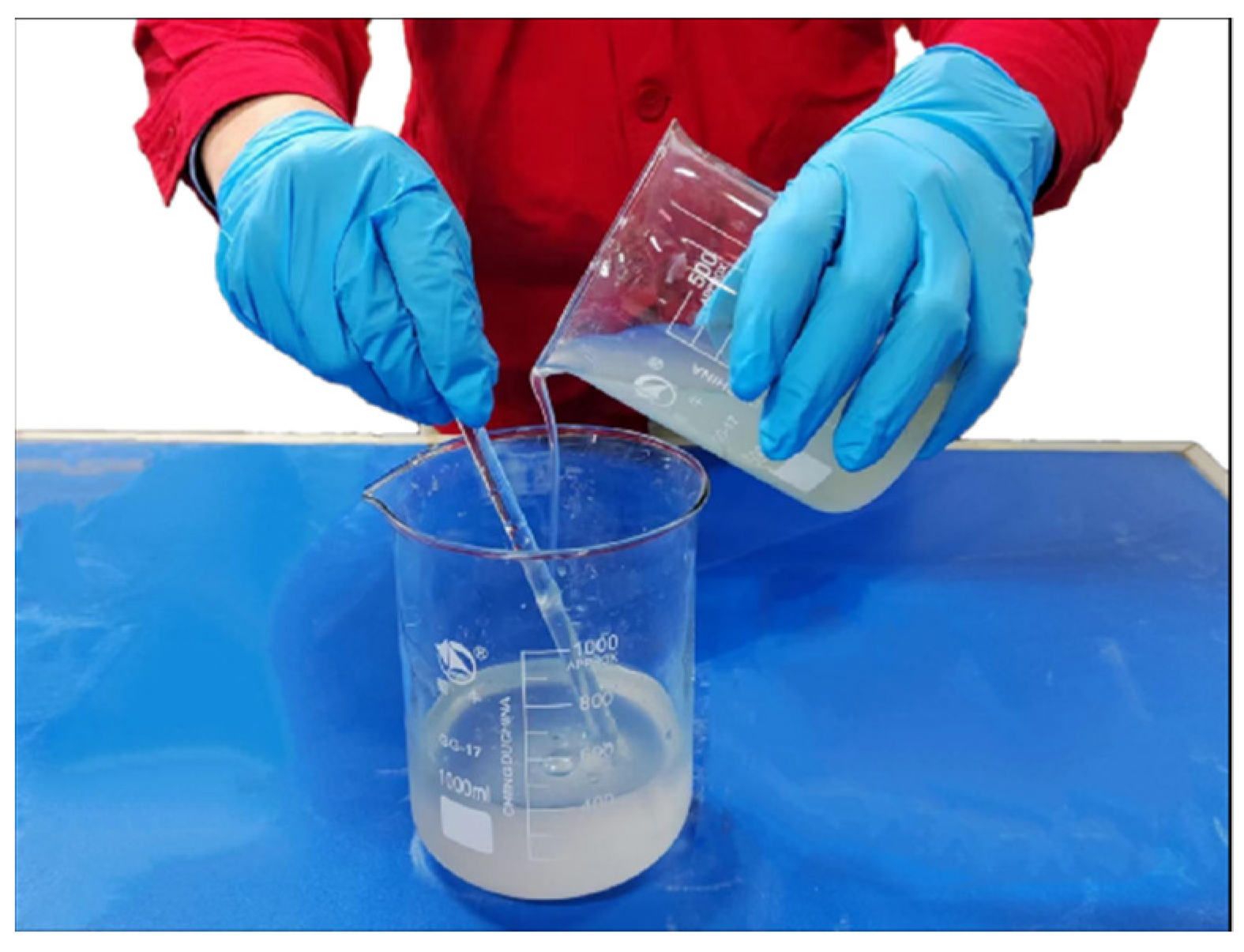
2.1. Grouting Slurry

It is key to prevent and control debris flow in underground mines to achieve infiltration grouting of the moraine to consolidate fine-particle moraine. The moraine has a high density and extremely narrow pore channels. The results of calculation and preliminary exploration have shown that if cement-based grouting materials are used to achieve infiltration grouting of moraine, more than 95% of the particles of grouting materials must be smaller than 1.972 μm (7606 mesh), but the existing technology cannot achieve this condition. It is difficult to achieve grouting penetration with conventional cement slurry, so the inorganic chemical grouting materials developed for moraine are used. The grout mainly consists of water glass, hardener, and additives. Hardener is used to control the solidification time of the slurry, while the additives are mainly used to adjust the viscosity of the slurry to improve the injectivity of the slurry and to modify the moraine to improve the injectivity of the moraine itself. Each component of the slurry used in the experiment was pre-configured and diluted according to the principle of “powder” in “water” and “alkali” in “acid”. The prefabricated water glass and hardener (including additives) were mixed 1:1 in the experiment, and the slurry configuration process is shown in Figure 1.

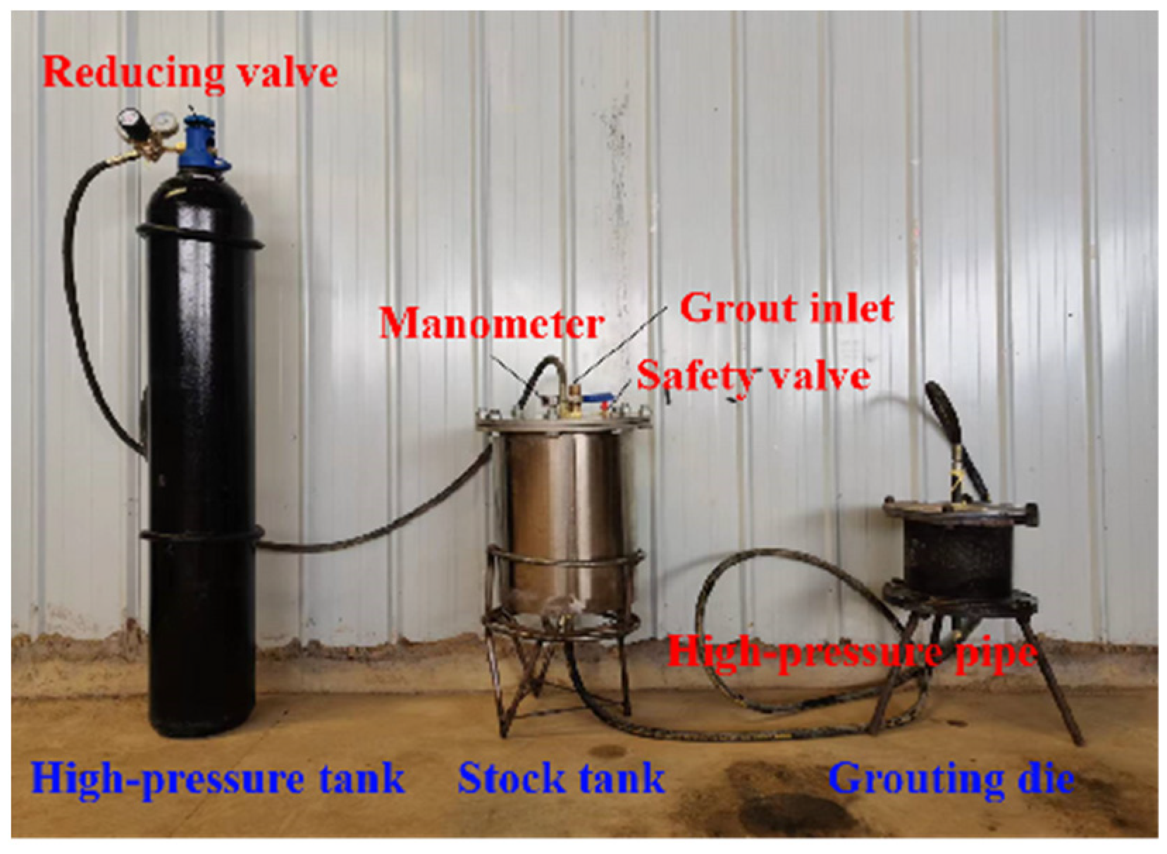
2.2. Experimental Device

The experimental apparatus comprised three components: a power unit (compressed air reservoir), slurry storage container, and grouting mold. They were interconnected by high-pressure hoses with a pressure of 30 MPa. Figure 2 illustrates the connection arrangement of the apparatus. Once the entire grouting system was assembled, the uniformly prepared slurry was poured into the slurry storage bucket. Compressed air was then injected into the same bucket to initiate the pressure grouting process, with any excess slurry being discharged through the pressure relief hole situated at the top of the mold.
The slurry storage drum was constructed as a steel cylinder measuring 30 cm in diameter and 60 cm in height. The top cover featured a funnel inlet, a safety valve set to 2.2 MPa, and a pressure gauge. The bottom of the drum was funnel-shaped, and a slurry outlet was located at the tip of the conical cone to ensure no slurry remained in the barrel. The maximum pressure of the slurry storage container was 20 MPa; however, for safety purposes and practical experimental requirements, the equipment’s maximum working pressure was limited to 2 MPa. The grouting pressure was able to be precisely regulated between 0.01 and 2.0 MPa by controlling the intake gas and pressure through an adjusted reducing valve, enabling stepless adjustment. The grouting mold was of cylindrical shape, measuring 100 mm in diameter and 200 mm in height. The main body of the mold was cut along the central axis to obtain a fully consolidated body after grouting. Flanges connect the parts, while sealed rings or gaskets were placed on all connections to enhance the air tightness of the mold and avert leakage of the slurry. Several tiny holes were positioned on the top of the mold to facilitate a seamless flow pathway for displaced substances like air and free water within the sample as part of the grouting process.

2.3. Sample Preparation

The moraines utilized in the experiment were collected from the surface subsidence area of Pulang Copper Mine. Moraines with a particle diameter exceeding 40 mm were eliminated, and the rest were dried in an oven. The oven was set to a temperature of 105 °C for 24 h. The dry moraines were sifted into two categories, namely, fine-grained moraines (−8 mm) and coarse-grained moraines (8–20 mm). Assembling the body and bottom of the mold after applying petroleum jelly to its interior was the final step. Based on the particle gradation used in the experiment, components of equivalent quality were weighed separately. Once fully mixed, each sample was divided into three equal parts, added successively to the mold, and compacted, before installing the top cover onto the mold.

2.4. Experimental Ratio

To investigate the impact of porosity and grouting pressure on moraine grouting, we conducted experiments on −8 mm moraine samples with densities of 1.9 g/cm3, 2.1 g/cm3, and 2.3 g/cm3, using chemical grout under various pressures (0.4 MPa, 0.8 MPa, 1.2 MPa, 1.6 MPa, and 2.0 MPa). We used 400 g grout for each experiment, which lasted 120 s. The equation for determining sample porosity is as follows:
n = 1 ρ D / ρ T
where: n—porosity, %;
ρD—sample dry density, g/cm3;
ρT—true density of sample, g/cm3.
The true density of the moraine was 2.66–2.68 g/cm3, with an average of 2.67 g/cm3, so the porosities of the three moraine samples were calculated as 28.84%, 21.35%, and 13.86%. The experimental parameters are shown in Table 1.
To further investigate the impact of pore diameter on the injectivity of the moraine samples, a specified quantity of coarse particles (measuring between 8 and 20 mm) was combined with the −8 mm moraine sample. Chemical grout was utilized to carry out grouting experiments on the moraine samples with 2.1 g/cm3 density. The experiments differed only in the proportion of coarse particle content, specifically varying between 50%, 60%, 70%, and 80%. A grouting pressure of 2.0 MPa was applied, while each experiment consisted of 400 g grout and 120 s grouting time. The effective diameter was determined by calculating the mean value of various particle diameters, as sample density and particle diameter have a significant impact on the pore diameter [33]:
D 0 = D 1 q 1 / 100
where: D0—the effective diameter of sand particles in the sand-layer medium, cm;
D1—medium diameter of sand particle gradation, cm;
q1—the percentage corresponding to the sieve diameter is the dimensionalized quantity.
The composition of the moraine was complex, the gradation was widely distributed, and the uniformity was poor, so it was simplified to an ideal round granular medium, whose pore diameter was [33]:
d 0 = 0.855 D 0 n 0.7245 / ( 1 n ) 0.5
where: D0—medium pore diameter, cm;
D1—effective particle diameter of sand medium, cm;
n—the porosity of sand medium.
Based on this, we obtained the effective and pore diameters of the moraine samples with varying amounts of coarse particles. The pore diameters of the moraine samples were determined to be 2.578 mm, 2.932 mm, 3.302 mm, and 3.671 mm. Table 2 displays the experimental parameters.

2.5. Criteria for Notability

The criteria for assessing the injectivity of moraine must be explicitly established before conducting an injectivity trial. The objective of the present experiment was to ascertain the injectivity of the injected medium based on the grouting depth of the slurry with respect to the given grouting pressure and time. Typically, when the grouting depth exceeds 90% of the grouting mold length, it is determined that the moraine can be fully injected. When the depth of grouting is less than 10% of the length of the grouting mold, it is deemed to be non-injectable. If the grouting depth ranges from 10% to 90% of the size of the grouting mold, then injection is deemed to be inadequate.
To ensure experimental accuracy, a grouting mold with a length of 200 mm was selected due to the use of coarse particles with a diameter of 20 mm in the experiment. Therefore, the criteria for assessing the injectivity of moraine were as follows:
(1)
Based on the experimental conditions, slurry with a grouting depth exceeding 18 cm was considered fully injectable.
(2)
If the slurry’s grouting depth was less than 2 cm, it could not be injected.
(3)
Grouting depths ranging from 2 to 18 cm were insufficient for injection purposes.
(4)
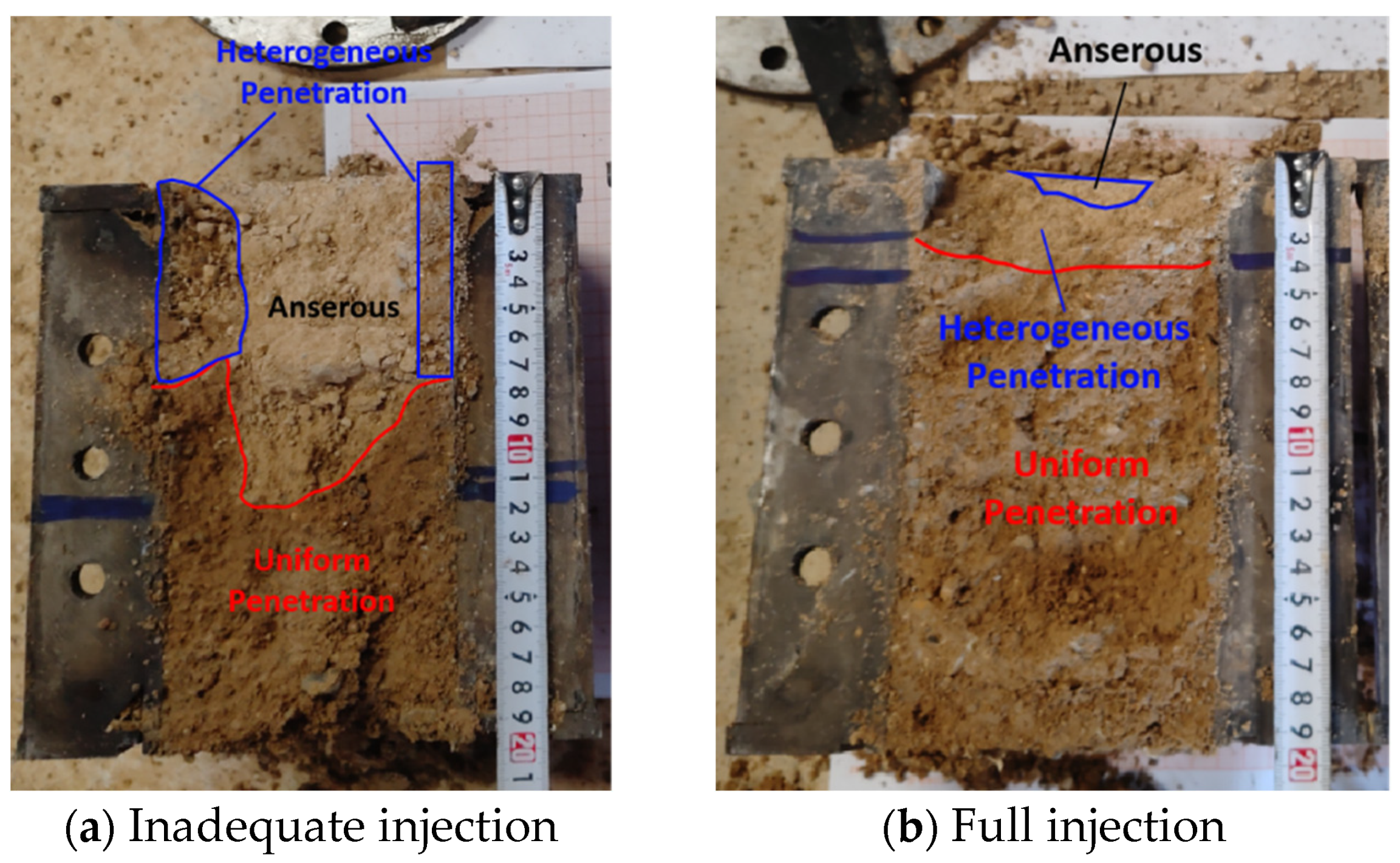
The portion of non-uniform penetration was decreased proportionally to the area ratio, as indicated in Figure 3.

3. Experimental Results and Analysis

As depicted in Figure 4, the injectivity test of the moraine demonstrated that the chemical slurry had excellent permeability, resulting in only two instances of complete injection and inadequate injection. When fully injected, the chemical slurry was uniformly distributed throughout most of the sample, with only a few areas at the far end of the slurry distribution being uneven or devoid of slurry, and the boundaries of each region were indistinct. Under conditions of suboptimal injection, the chemical grout only occupied a restricted portion of the sample, resulting in a significantly larger non-grouted area than the area of irregular penetration. The boundaries of each area were easily discernible, and the three distinctions were evident. At this point, the slurry’s penetration capacity had reached the limits of the working conditions.
Through the grouting seepage experiment on the moraine samples, the experimental results of the injectivity under different conditions were obtained. The experimental results for the influence of sample porosity and grouting pressure on the injectivity of moraine samples are shown in Table 3. It was found that the grouting depth of moraine increased with the increase of grouting pressure and sample porosity.
Table 4 displays the outcomes of experiments that investigated the impact of pore diameter on the moraine’s injection ability when the samples had uniform porosity. The results indicate that as the samples’ coarse particle content rose, their effective particle diameter and pore diameter also increased, while the slurry’s grouting depth decreased.

3.1. Influence of Porosity on the Injectivity of Moraine

Figure 5 displays the grouting status of moraine samples of varying porosities. It is apparent from the illustration that the depth of the grouting increased proportionally with the porosity of the samples for identical grouting pressures. Porosity significantly affected each sample’s injection capability; however, as the porosity increased, its impact on injection depth dwindled. The moraine sample had a loose packing density of 1.47 g/cm3 and a loose porosity of 44.74%. Consequently, infiltration grouting was able to be achieved through the dead weight of the slurry without any additional pressure. Alternatively, the need for higher grouting pressure increased when the porosity was lower at the same grouting depth.

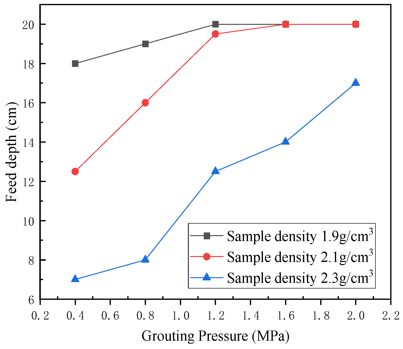
3.2. Influence of Grouting Pressure on the Injectivity of Moraine

Figure 6 displays the grouting conditions of moraine samples subjected to varying grouting pressures. It is evident from the figure that when the samples had the same density, their grouting depth increased with an increase in grouting pressure. Nevertheless, because of the size limitations of the mold, any grouting depth beyond 20 cm could not be accounted for. In cases where the grouting depth was below 20 cm, the depth of grouting was positively linked to the pressure of grouting.
After excluding data where grouting depths exceeded 20 cm, a linear equation showing the correlation between grouting pressure and depth was obtained for samples of varying densities. Additionally, the grouting pressure required for a depth of 18 cm in samples with different densities was calculated. Table 5 displays the corresponding parameters.
Figure 7 shows the relationship between the density of the moraine samples and the pressure of the osmotic grouting. Nonlinear fitting was used to obtain the relationship between the density of moraine samples and the pressure required to achieve osmotic grouting.
P = 0.0146 ρ 8.78515 R 2 = 0.99
The correlation between grouting pressure, the experimental density of the moraine, and grouting depth is illustrated in Figure 8. It is evident from the figure that as the grouting pressure increases and the sample density decreases, the grouting depth of moraine progressively rises. By fitting, the following relationship between grouting pressure, sample density, and grouting depth was established:
H = 66.87597 + 6.35877 P 27.0974 ρ R 2 = 0.93764

3.3. Influence of Pore Diameter on the Injectivity of Moraine

Figure 9 exhibits the outcomes of the grouting injectivity experiments conducted on moraine samples with varying pore diameters under comparable grouting pressures and densities. The data reveal that the grouting depth of the samples steadily diminished in proportion to the diameter of their pores.
When the density of the moraine samples was the same as the grouting pressure, the grouting depths and pore diameters of the grouting of moraine samples with different pore diameters were approximately linearly related to the chemical grout. By fitting linearly, the relationship between the grouting pressure and grouting depth of the moraine was able to be determined.
h = 55.198 13.441 r
where: r—pore diameter, mm;
h—feed depth, cm.

4. Grouting Mechanism Analysis

As pore diameter increases, there is a significant change in the diffusion mode of chemical grouting. This is because the particle uniformity within a fine-particle sample improves, resulting in a more uniform pore size of the chemical grout in the sample. As a result, there are no apparent weak points, and the resistance of the grout to spreading around is consistent. This leads to an even spread of the grout without forming a dominant channel, causing the grout to primarily spread in a unidirectional shape.
Grouting depth H can be defined as:
H = vt
The rheological properties of the chemical grout utilized in this experiment exhibit a relatively intricate nature. Following the amalgamation of each component, the viscosity of the grout undergoes temporal and compositional variations, yet all experience two distinct stages during specimen growth. In the initial stage, the viscosity gradually increases with minimal change; at this point, the fluidity of the grout is exceptionally high, akin to water. Once a certain threshold is reached—the viscosity point—the second stage commences wherein the slurry viscosity rapidly escalates until it sets. Throughout grouting, when there are negligible alterations in rheological properties, the grout remains continuous and uniform while being nearly incompressible, thus resembling an ideal fluid. The movement of grout adheres to energy conservation principles; henceforth, both kinetic and potential energies should remain constant—a phenomenon that aligns with Bernoulli’s principle. According to Bernoulli’s equation:
P / ρ + v 2 / 2 + g h = a
It can be seen that the slurry flow rate v is as follows:
v = 2 ( a g h P / ρ )
When Equation (9) is substituted into Equation (7), the grouting depth “H” is as follows:
H = v t = 2 ( a g h P / ρ ) · t
When the sample densities are identical, the porosity and resistance of the samples remain consistent. Moreover, there is a positive correlation between the grouting pressure and the grouting depth. When the grouting time is constant, an increase in grouting pressure leads to an increase in grouting depth, according to the following pressure formula:
P = F/A
It is known that under equal pressure, the slurry applies the same outward force on the medium. As the sample density rises, the sample’s porosity decreases and resistance increases. Consequently, the slurry’s grouting depth decreases with a higher sample density.
Adding coarse particles alters the internal structure of the sample. At constant density, the increase in coarse particle content causes a shift in the internal structure from a suspended formation to that of a skeleton structure composed of coarse particles. Since coarse particles can be considered to be dense regions whose density is approximately their true density, the actual density of the sample is lower than that of a pure fine-grained sample. As a consequence, the pore channel diameter increases. Additionally, the incorporation of coarse particles diminishes the homogeneity of the sample, leading to a larger pore diameter in the vicinity of the coarse particles than in the area enriched by fine particles. Although the diffusion resistance of the slurry in the fine-particle enrichment region is consistent, the coarse particles act as a barrier, preventing the slurry from penetrating. As a result, the pressure in the region is transferred to the depth along the outline of the coarse particles, creating higher pressure around the coarse particles than in other uniform areas of the fine particles. The larger pore diameter and greater pressure reduce the diffusion resistance of the slurry near coarse particles, especially between adjacent ones. Therefore, it is probable that the slurry will diffuse into the depth of the sample via the larger pores between the coarse particles. This event will lead to the formation of the dominant channel (splitting channel). However, the formation of the dominant channel facilitates the rapid movement of the slurry through it, increasing the likelihood of spreading and splitting along the next weaker segment of the channel with lower resistance. Some grout diffuses under pressure, with the dominant channel acting as the core. However, due to the greater resistance in the surrounding areas compared to deep splitting, the distance of grout diffusion is smaller. This ultimately results in a grouting mode with split grouting as the main technique and permeation grouting as the supporting approach.

5. Conclusions

Chemical grout was employed to conduct experiments on the injectivity of moraine. The effects of grouting pressure, sample porosity, and pore diameter on the injectivity of moraine led to the following conclusions:
(1)
The density of the moraine samples decreased, resulting in an increase in sample porosity and the entering depth of chemical slurry.
(2)
When keeping the density of samples constant, increasing the grouting pressure increases the grouting depth of the chemical slurry, and this increase is approximately linear. The relationship between sample density, grouting pressure, and grouting depth can be expressed as H = 66.87597 + 6.35877P − 27.0974ρ when grouting a fine-drift (−8 mm) sample.
(3)
At equal sample densities, an increase in coarse particle content leads to an overall increase in the effective particle diameter and pore diameter. As a result, the longitudinal grouting depth of the sample increases, while the transverse diffusion distance decreases, ultimately leading to a decrease in the final penetration distance of the sample. The outcome is the formation of a grouting mode in which split grouting plays the main role, with penetration grouting serving as an auxiliary.
In order to continue to improve upon the relevant experiments, it will be necessary to explore the relationships between grouting pressure, particle gradation, sample density, grouting depth, and other progressive parameters; observe the motion state of chemical grout in samples and the grouting effect using more means; and establish an injectivity model for penetration grouting.

Author Contributions

Investigation, Z.L. and W.S.; methodology, Z.L.; conceptualization, W.S.; writing—original draft preparation, Z.L.; funding acquisition, W.S.; writing—review and editing, W.S.; supervision, X.F. and S.W.; visualization, C.C. and H.S.; validation, M.J.; data curation, K.F. All authors have read and agreed to the published version of the manuscript.

Funding

This work was supported by the National Natural Science Foundation of China [51964023]; the Deep Green Exploration and Safe Mining of Key Metal Mineral Resources concentration areas of major science and technology projects in Yunnan Province [202202AG050014]; and the Basic Research Project of Yunnan Province [NO. 202101BE070001-038; 202201AT070146].

Data Availability Statement

The raw data supporting the conclusions of this article will be made available by the authors on request.

Acknowledgments

We would like to take this opportunity to express our heartfelt thanks to the Yunnan Diqing Nonferrous Metal Co., Ltd., for their support and help during the research process.

Conflicts of Interest

Author Feng X was employed by the company Yunnan Diqing Nonferrous Metal Co., Ltd. The remaining authors declare that the research was conducted in the absence of any commercial or financial relationships that could be construed as a potential conflict of interest.

Abbreviations

n porosity.
ρDdry density of sample.
ρTtrue density of sample.
D0the effective diameter of sand particles in the sand-layer medium.
D1medium diameter of sand particle gradation.
q1the percentage corresponding to the sieve diameter is the dimensionalized quantity.
D0medium pore diameter.
D1effective particle diameter of sand medium.
nthe porosity of sand medium.
rpore diameter.
hfeed depth.

References

  1. Yang, D.; Wang, J.; Yang, D. Evaluation method of slope structure and stability of moraine in Palong Zangbu Basin. Yangtze River 2019, 50, 108–112+129. [Google Scholar]
  2. Wang, T.; Song, D.; Dun, Z. Dynamic compaction treatment and test detection of plateau airport moraine soil foundation. Geotech. Eng. Tech. 2012, 26, 152–154. [Google Scholar]
  3. Feng, X.; Li, Z.; Jiang, M.; Wang, S.; Chen, C.; Sun, W. Experimental study of soil erosion on moraine-consolidated slopes under heavy rainfall. Heliyon 2024, 10, e26721. [Google Scholar] [CrossRef]
  4. Chen, J.; Liu, L.; Zeng, B.; Tao, K.; Zhang, C.; Zhao, H.; Li, D.; Zhang, J. A constitutive model to reveal the anchorage mechanism of fully bonded bolts. Rock Mech. Rock Eng. 2023, 56, 1739–1757. [Google Scholar] [CrossRef]
  5. Xia, X. Research on Optimization Ratio of Grouting Materials and Grouting Test. Master’s Thesis, Anhui University of Science and Technology, Huainan, China, 2012. [Google Scholar]
  6. Yang, Y.; Xua, H.; Li, K.; Geng, H.; Ma, L. Experimental study on the injectivity of calcareous sand by permeation grouting. Prot. Eng. 2020, 42, 10–17. [Google Scholar]
  7. Zou, H. Study on Mechanism and Effect Evaluation of Grouting Diffusion Reinforcement of Soil-Rock Mixed Backfill. Master’s Thesis, Chongqing University, Chongqing, China, 2022. [Google Scholar]
  8. Ren, J.; Zhao, H.; Zhang, L.; Zhao, Z.; Xu, Y.; Cheng, Y.; Wang, M.; Chen, J.; Wang, J. Design optimization of cement grouting material based on adaptive boosting algorithm and simplicial homology global optimization. J. Build. Eng. 2022, 49, 104049. [Google Scholar] [CrossRef]
  9. Qian, Z.; Jiang, Z.; Cao, L.; Sun, Q. Model test of porous media grouting with weak cementation. Rock Soil Mech. 2013, 34, 139–142+147. [Google Scholar]
  10. Zhang, L.; Zhang, Q.; Liu, R.; Li, S.; Wang, H.; Li, W.; Zhang, S.; Zhu, G. Study on diffusion mechanism of quick-setting grout infiltration grouting considering temporal and spatial changes of grout viscosity. Rock Soil Mech. 2017, 38, 443–452. [Google Scholar]
  11. Chen, X.; Rong, Y.; Jiao, H.; Yang, L.; Zhang, H.; Zhang, W. Strength Laws and Crack Evolution Mechanism of Slurry Grouting under High-Permeability and High-Stress Curing Conditions. Buildings 2022, 12, 1236. [Google Scholar] [CrossRef]
  12. Maghous, S.; Saada, Z.; Dormieux, L.; Canou, J.; Dupla, J.C. A model for in situ grouting with account for particle filtration. Comput. Geotech. 2007, 34, 164–174. [Google Scholar] [CrossRef]
  13. Bouchelaghem, F. Multi-scale modelling of the permeability evolution of fine sands during cement suspension grouting with filtration. Comput. Geotech. 2009, 36, 1058–1071. [Google Scholar] [CrossRef]
  14. Zeng, Q.; Gao, P.; Li, K.; Dong, G.; Jin, G.; Sun, X.; Zhao, J.; Chen, L. Experimental Research on the Properties and Formulation of Fly Ash Based Geopolymer Grouting Material. Buildings 2022, 12, 503. [Google Scholar] [CrossRef]
  15. Güllü, H.; Yetim, M.E.; Güllü, E.B. Effect of using nano-silica on the rheological, fresh and strength characteristics of cement-based grout for grouting columns. J. Build. Eng. 2023, 76, 107100. [Google Scholar] [CrossRef]
  16. Wang, A.; Li, Z.; Liu, P.; Liu, K.; Yu, G.; Zheng, Q.; Han, Y.; Xu, H.; Sun, D. Preparation and Properties of Double Liquid Grouting Materials (DLGMs) Used for the Regenerated Roof of a Coal Mine. Buildings 2023, 13, 584. [Google Scholar] [CrossRef]
  17. Zhong, Z.; Bie, C.; Fan, Y. Experimental study on grouting diffusion mechanism and influencing factors of soil-rock mixture. Rock Soil Mech. 2019, 40, 4194–4202. [Google Scholar]
  18. Jiang, X.; Zhu, H.; Yan, Z.; Yan, Z.; Zhang, F.; Ye, F.; Li, P.; Zhang, X.; Dai, Z.; Bai, Y.; et al. A state-of-art review on development and progress of backfill grouting materials for shield tunneling. Dev. Built Environ. 2023, 16, 100250. [Google Scholar] [CrossRef]
  19. King, J.C.; Bush, D. Symposium on grouting of granular materials. J. Soil Mech. Found. Div. ASCE 1961, 87, 1–31. [Google Scholar] [CrossRef]
  20. Mitchell, J.K. In-place treatment of foundation soils. J. Soil Mech. Found. Div. ASCE 1970, 96, 73–109. [Google Scholar] [CrossRef]
  21. Incecik, M.; Ceren, I. Cement grouting model tests. Bull. Tech. Univ. Istanb. 1995, 48, 305–317. [Google Scholar]
  22. Akbulut, S.; Saglamer, A. Estimating the groutability of granular soils: A new approach. Tunn. Undergr. Space Technol. Inc. Trenchless Technol. Res. 2002, 17, 371–380. [Google Scholar] [CrossRef]
  23. Kim, J.S.; Lee, I.M.; Jang, J.H.; Choi, H. Groutability of cement-based grout with consideration of viscosity and filtration phenomenon. Int. J. Numer. Anal. Methods Geomech. 2009, 33, 1771–1797. [Google Scholar] [CrossRef]
  24. Zhang, L. Mechanism and Engineering Application of Grouting Diffusion and Reinforcement in Subway Crossing Sand Layer. Ph.D. Thesis, Shandong University, Jinan, China, 2017. [Google Scholar]
  25. Xiong, L. Seepage Grouting Mechanism and Experimental Study of Water-Rich Sand Layer Considering Percolation Effect. Ph.D. Thesis, Beijing Jiaotong University, Beijing, China, 2021. [Google Scholar]
  26. Liu, H. Study on the Flocculation Effect of Cement Slurry Particles and the Injectivity of Porous Media. Master’s Thesis, Shandong University, Jinan, China, 2019. [Google Scholar]
  27. Liu, L.; Wang, H.; Zheng, S.; Dong, L.; Yu, Y.; Yang, C. Damage Model and Experimental Study of a Sand Grouting-Reinforced Body under Seepage. Processes 2022, 10, 256. [Google Scholar] [CrossRef]
  28. Nguyen, T.T.; Indraratna, B. The energy transformation of internal erosion based on fluid-particle coupling. Comput. Geotech. 2020, 121, 103475. [Google Scholar] [CrossRef]
  29. Tang, Y. Study on the Permeability of Saturated Sand Tunnel Surrounding Rock under Dynamic Water Conditions Based on CFD-DEM. Master’s Thesis, Guangdong University of Technology, Guangzhou, China, 2023. [Google Scholar]
  30. Zhu, G.; Zhang, Q.; Liu, R.; Zhang, L.; Guo, Y. Sand streamability prediction model based on PSO-LSSVM and its sensitivity analysis. J. Harbin Inst. Technol. 2020, 52, 175–182. [Google Scholar]
  31. Fraccica, A.; Spagnoli, G.; Romero, E.; Arroyo, M.; Gómez, R. Permeation grouting of silt-sand mixtures. Transp. Geotech. 2022, 35, 100800. [Google Scholar] [CrossRef]
  32. Yu, X. Preparation and structure analysis of aluminum oxide/water glass/polyurethane composite grouting material for mining. J. Build. Eng. 2023, 76, 107170. [Google Scholar] [CrossRef]
  33. Geotechnical Grouting Theory and Engineering Practice Group. Geotechnical Injection Theory and Engineering Example; Science Press: Beijing, China, 2011. [Google Scholar]
Figure 1. Configurations of the slurry.
Water 16 00728 g001
Figure 2. Grouting experimental equipment.
Water 16 00728 g002
Figure 3. Measurement of grouting parameters.
Water 16 00728 g003
Figure 4. Section of permeable grouting sample.
Water 16 00728 g004
Figure 5. Relationships between sample porosity and grouting depth.
Water 16 00728 g005
Figure 6. Relation between grouting pressure and grouting depth.
Water 16 00728 g006
Figure 7. Grouting density and grouting pressure.
Water 16 00728 g007
Figure 8. Relationship between grouting pressure, sample density, and grouting depth.
Water 16 00728 g008
Figure 9. The relationship between the pore diameter of the moraine and the depth of grouting.
Water 16 00728 g009
Table 1. Study of the injectivity of chemical grouting materials.
IDGrouting Quantity
/g
Grouting Pressure
/MPa
Maximum Particle Size
/mm
Density
/g/cm3
Porosity
/%
HX1400 g0.4 MPa8 mm1.9 g/cm328.84%
HX2400 g0.8 MPa8 mm1.9 g/cm328.84%
HX3400 g1.2 MPa8 mm1.9 g/cm328.84%
HX4400 g1.6 MPa8 mm1.9 g/cm328.84%
HX5400 g2.0 MPa8 mm1.9 g/cm328.84%
HX6400 g0.4 MPa8 mm2.1 g/cm317.23%
HX7400 g0.8 MPa8 mm2.1 g/cm317.23%
HX8400 g1.2 MPa8 mm2.1 g/cm317.23%
HX9400 g1.6 MPa8 mm2.1 g/cm317.23%
HX10400 g2.0 MPa8 mm2.1 g/cm317.23%
HX11400 g0.4 MPa8 mm2.3 g/cm313.86%
HX12400 g0.8 MPa8 mm2.3 g/cm313.86%
HX13400 g1.2 MPa8 mm2.3 g/cm313.86%
HX14400 g1.6 MPa8 mm2.3 g/cm313.86%
HX15400 g2.0 MPa8 mm2.3 g/cm313.86%
Table 2. Experimental parameters of the impact of pore diameter on injectivity.
IDType of SlurryDensity
/g/cm3
Grouting Quantity
/g
8–20 mm
Content
Grouting Pressure
/MPa
Effective Particle Diameter
/mm
Pore Diameter
/mm
KX1Chemical slurry2.1 g/cm3400 g50%2.0 MPa8.1912.578
KX2Chemical slurry2.1 g/cm3400 g60%2.0 MPa9.3102.932
KX3Chemical slurry2.1 g/cm3400 g70%2.0 MPa10.4833.302
KX4Chemical slurry2.1 g/cm3400 g80%2.0 MPa11.6553.671
Table 3. Experimental results for the injectivity of chemical grouting materials.
IDGrouting Pressure
/MPa
Density
/g/cm3
Porosity
/%
Feed Depth
/cm
Notability Determination
HX10.4 MPa1.9 g/cm328.84%18 cmFully injectable
HX20.8 MPa1.9 g/cm328.84%19 cmFully injectable
HX31.2 MPa1.9 g/cm328.84%20 cmFully injectable
HX41.6 MPa1.9 g/cm328.84%20 cmFully injectable
HX52.0 MPa1.9 g/cm328.84%20 cmFully injectable
HX60.4 MPa2.1 g/cm317.23%12.5 cmInsufficient injection
HX70.8 MPa2.1 g/cm317.23%16 cmInsufficient injection
HX81.2 MPa2.1 g/cm317.23%19.5 cmFully injectable
HX91.6 MPa2.1 g/cm317.23%20 cmFully injectable
HX102.0 MPa2.1 g/cm317.23%20 cmFully injectable
HX110.4 MPa2.3 g/cm313.86%7 cmInsufficient injection
HX120.8 MPa2.3 g/cm313.86%9 cmInsufficient injection
HX131.2 MPa2.3 g/cm313.86%12.5 cmInsufficient injection
HX141.6 MPa2.3 g/cm313.86%14 cmInsufficient injection
HX152.0 MPa2.3 g/cm313.86%17 cmInsufficient injection
Table 4. The impact of pore diameter on moraine injectivity based on experimental data.
IDType of Slurry8–20 mm Content
/%
Pore Diameter
/mm
Feed Depth
/cm
Grouting Quantity
/g
KX1Chemical slurry50%2.57820124
KX2Chemical slurry60%2.9321779
KX3Chemical slurry70%3.3021079
KX4Chemical slurry80%3.671644
Table 5. Correlation between sample density, porosity, and grouting pressure.
Sample Density ρ
g/cm2
Porosity
%
Fitting FormulaInjection Grouting Pressure
1.928.84%H = 2.5P + 170.4
2.117.23%H = 8.75P + 91.0
2.313.86%H = 6.25P + 4.42.2
Disclaimer/Publisher’s Note: The statements, opinions and data contained in all publications are solely those of the individual author(s) and contributor(s) and not of MDPI and/or the editor(s). MDPI and/or the editor(s) disclaim responsibility for any injury to people or property resulting from any ideas, methods, instructions or products referred to in the content.

