Article

Simulation of the Entire Process of an Interbasin Water Transfer Project for Flow Routing

State Key Laboratory of Eco-Hydraulics in Northwest Arid Region of China, Xi’an University of Technology, Xi’an 710048, China
*
Author to whom correspondence should be addressed.
Water 2024, 16(4), 572; https://doi.org/10.3390/w16040572
Submission received: 10 January 2024 / Revised: 6 February 2024 / Accepted: 14 February 2024 / Published: 15 February 2024
(This article belongs to the Section Hydrology)

Abstract

:
The flow routing process plays a crucial role in underpinning the execution of real-time operations within interbasin water transfer projects (IWTPs). However, the water transfer process within the supplying area is significantly affected by the time lag of water flow over extended distances, which results in a misalignment with the water demand process in the receiving area. Hence, there is an imperative need to investigate the flow routing patterns in long-distance water transfer processes. While MIKE11(2014 version) software and the Muskingum method are proficient in simulating flow routing within a water transfer network, they fall short in addressing issues arising from mixed free-surface-pressure flows in water transfer pipelines. This study enhanced the capabilities of the MIKE11(2014 version) software and the Muskingum method by introducing the Preissmann virtual narrow gap method to tackle the challenge of simulating mixed free-surface-pressure flows, a task unattainable by the model independently. This approach provides a clear elucidation of hydraulic characteristics within the water transfer network, encompassing flow rates and routing times. Furthermore, this is integrated with the Muskingum inverse method to compute the actual water demand process within the supplying area. This methodology is implemented in the context of the Han River to Wei River Diversion Project (HTWDP). The research findings reveal that the routing time for the Qinling water conveyance tunnel, under maximum design flow rate conditions, is 12.78 h, while for the south and north main lines, it stands at 15.85 and 20.15 h, respectively. These results underscore the significance of the time lag effect in long-distance water conveyance. It is noteworthy that the average errors between simulated and calculated values for the south and north main lines in the flow routing process are 0.45 m3/s and 0.51 m3/s, respectively. Compared to not using the Preissmann virtual narrow gap method, these errors are reduced by 59.82% and 70.35%, indicating a significant decrease in the discrepancy between simulated and calculated values through the adoption of the Preissmann virtual narrow gap method. This substantially improves the model’s fitting accuracy. Furthermore, the KGE indices for the flow routing model are all above 0.5, and the overall trend of the reverse flow routing process closely aligns with the simulated process. The relative errors for most time periods are constrained within a 5% range, demonstrating the reasonability and precision of the model.

1. Introduction

The intensification of human activities and the uneven spatial and temporal distribution of water resources have gradually become important factors restricting the sustainable development of ecology and society. With the continuous development of the economy and the increasing demand for water, higher requirements have been put forward for the reasonable distribution of water resources. IWTPs transport water resources from water-rich supply areas to water-scarce receiving areas through water transmission pipe networks, realizing the redistribution of water resources and effectively alleviating the water shortage status of many basins [1,2,3,4,5]. Current research on IWTPs mainly focuses on the optimal dispatch of reservoirs in water-diversion areas and the optimal allocation of water in water-receiving areas. Mingbo et al. [6] explored multi-objective dispatch rules for IWTPs by considering runoff uncertainty; Guo et al. [7] proposed a new multi-objective optimization algorithm (r-MQSFLA) for IWTPs to improve the search quality of operation plans in the optimization process; Sousa Estácio et al. [8] comprehensively considered environmental and social factors and evaluated people’s perception of drought in water resource allocation. The above research mainly focused on the management of water quantity and did not consider the transportation process in IWTPs. The water transmission pipeline network is an indispensable and important part of the entire water diversion system, connecting the water-supplying area and the water-receiving area. The key is that the water will be accompanied by a time lag effect during the transportation process, resulting in a mismatch between the real-time supply and demand processes. Therefore, it is necessary to study the entire flow routing process of the IWTP.
In IWTPs, the transportation of water undergoes considerable alteration influenced by variables such as the length, dimensions, and mode of transportation within the pipeline network. These factors significantly impact its internal hydraulic characteristics. Numerous scholars and experts have delved into exploring these hydraulic features. Gao et al. [9] established a hydrological and hydrodynamic model by combining the MIKE11 model and the hydrological modeling system to explore the changes in a river network’s connectivity with flood control measures. The results showed that dike-type flood control measures have a negative impact on the connectivity of the river network, and attention should be paid to the number and opening and closing status of water pumps. Lagos et al. [10] reduced the instability of numerical results by adjusting the time step and tunnel topography in the MIKE-SHE and MIKE-11 models, and the results showed that surface flow can be reduced after removing the tunnel. In addition, to compare with the MIKE-11 model, Yi et al. [11] established a one-dimensional hydrodynamic and water quality model to simulate the flow pattern of water in each hydraulic structure. The results showed that the model has good simulation and accuracy. The process of long-distance water transportation is more obviously affected by changes in water flow, and its monitoring data directly affect subsequent simulation research. Ren et al. [12] established an inversion data cleaning model and verified it; the results showed that the cleaning model improved the accuracy of the flow monitoring data. However, the above research mainly focused on local basin water transfer projects, and there are few studies on flow routing in IWTPs. At the same time, due to the diverse structures of long-distance water pipeline networks and complex hydraulic connections, it is impossible to use a single model or method. To realize the simulation of the routing of water flow in the pipe network, it is crucial to establish a suitable model to simulate the routing process of water flow in different pipes and solve problems such as a mixed free-surface-pressure flow transition to clarify the real-time water supply after routing.
In addition, the Muskingum method is widely used in the study of flow routing in water delivery structures such as rivers, open channels, and tunnels. Bozorg et al. [13] established four improved nonlinear Muskingum models. The simulation results showed that the model’s ability to predict river flow is better than other models’, and the accuracy of the model was verified through examples. In addition, Sahoo et al. [14] proposed the Multilinear Muskingum Discharge Routing Method, which adequately simulated the flood wave propagation characteristics in the river channel and verified the applicability of the method. Parameter determination is the key to the Muskingum model. Kang et al. [15] established a Muskingum model that considers both cross-flow and variable index parameters, the results showed that the model can better fit the measured runoff, and the model accuracy has been further improved. Improve. At the same time, Hamedi et al. [16] combined the storage moving average with the nonlinear Muskingum model to apply the newly established model to the calculation of water storage capacity in irrigation channels, and the simulation results obtained were better than those of the traditional Muskingum model. Numerous studies have corroborated the efficacy of the Muskingum model in water flow routing research. Nonetheless, the Muskingum model’s computations rely on historical runoff data, posing challenges for projects yet to commence operations due to the unavailability of such data. This limitation impedes the practical application of the Muskingum method. Furthermore, factors like data discontinuity exert a notable impact on the model’s accuracy, presenting challenges for water transfer projects under construction in devising operational plans. The pivotal challenge lies in determining runoff data and integrating them effectively with the Muskingum model. This integration is crucial for accurately simulating the flow routing dynamics of water transfer projects that are still under construction.
Conventional flow routing simulation is adept at determining the time required for flow routing subsequent to the discharge from an upstream reservoir. This simulation process furnishes essential data supporting the real-time management of downstream reservoir operations [17,18,19]. By specifying either the downstream water level or the required water demand, it becomes feasible to invert the corresponding period’s volume of water released from the upstream source. This inversion process facilitates the realization of real-time operational adjustments for the upstream reservoir. To obtain the operation plan for the upper reaches of the river, Bozorg-Haddad et al. [20] proposed two nonlinear Muskingum inversion simulation methods based on Euler equations and Runge–Kutta 4th order equations, and they verified them with historical data. The results showed that the second method had a better fitting effect. Similarly, Gąsiorowski et al. [21] verified the rationality and accuracy of the two equations in the open-channel flow inversion model by performing a reverse integral inverse solution in the x direction of the linear motion wave equation and the linear Muskingum equation. At the same time, Badfar et al. [22] established a flow inversion model based on the Muskingum model. In this model, the storage function is conceptualized as being linear and having five different nonlinear forms, and the shuffled complex routing algorithm is used for parameter optimization; the results showed that the efficiency of the model fitting was improved. The Muskingum inversion method demonstrates efficacy in simulating upstream discharge scenarios within water transfer projects. However, the application of this method encounters a heightened complexity within IWTPs owing to the intricate network of pipelines. The presence of water diversions in the water-receiving area further compounds these challenges. Resolving this intricate systemic issue represents the crux in attaining real-time operational capabilities within IWTPs.
In summary, this paper takes the HTWDP as the research object and proposes a whole-process flow routing simulation system for the IWTP. The system is composed of a forward flow routing model and a reverse flow routing model. Firstly, the Preissmann virtual narrow gap method was used in combination with MIKE-11 to model the forward flow routing model for the problem of mixed free-surface-pressure flow. Then, the simulation results of the model were used as the input of the Muskingum model to calibrate the parameters and verify the model. Finally, based on the forward calculation results and parameter rate settings, the reverse flow inversion model was used to obtain the upper-section flow process of the project. The Muskingum inversion method is the core of the reverse flow routing model. This system provides a theoretical basis for the possibility of the real-time operation of IWTP.

2. Materials and Methods

2.1. Overview

The Han River basin experiences distinct seasons throughout the year, with pronounced spring and autumn dryness, hot and rainy summers, and cold and dry winters. The average annual precipitation ranges from 800 to 1200 mm. Based on multi-year observational data, the average annual runoff in the Shaanxi section of the Han River Basin is 24.7 billion m3, exhibiting a decreasing trend from west to east, with a runoff depth ranging from 300 to 850 mm. The water resources are relatively abundant. Simultaneously, the Wei River is the largest tributary of the Yellow River and is situated in the transition zone between arid and humid regions. The basin has an average annual precipitation of 572 mm (based on data from 1956 to 2000), with a trend of a higher precipitation in the South and in mountainous areas compared to the northern and basin regions. The total surface water resources in the area amount to 8.928 billion m3, with an average annual outflow of 7.997 billion m3. Notably, the outflow from the Wei River accounts for 90.3% of the total outflow in the water-receiving area. The available water resources in the region are insufficient to meet the needs of various local water-consuming sectors, with a per capita availability of 304 m3, only 14% of the national average. Moreover, due to human activities, water resources in the Wei River basin are increasingly scarce, and water quality is deteriorating, exacerbating the degradation of the ecological environment. Therefore, the HTWDP serves as a crucial means to enhance ecological environmental protection and efficient water resource utilization in the Wei River basin. It has become a key initiative in addressing the ecological and water resource challenges in the receiving area, and the urgency for project construction is evident.
The HTWDP spans the Han River basin and the Wei River basin, and it transports the abundant water resources in the Han River basin to the relatively water-scarce Wei River basin through the water transmission pipeline network. The long-term target water transfer volume is 1.5 billion m3. Among them, the water transmission and distribution project with the water transmission pipeline network as the core is an important part connecting the water transfer area and the water receiving area, and its operating status directly affects the satisfaction of supply and demand matching. The water transmission and distribution project consists of the Qinling water conveyance tunnel, Huangchigou water distribution hub, south main line, north main line, and corresponding water transmission branch lines. The project starts from the Huangsan section of the Qinling water conveyance tunnel, passes through the Yueling section to the Huangchigou water distribution project, and then transports water to the south and north main lines. The south and north main lines run to Yangling in the west, Huazhou district in the east, and Huazhou district in the north. Fuping, extending to Huyi in the south, is about 163 km long from east to west and 84 km wide from north to south, with a total area of about 14,000 km2. The direct water supply targets of the water-receiving area are Xi’an city, Xianyang city, Weinan city, and Yangling district 4 on both sides of the Wei River in the Guanzhong area. A key city and its 11 county-level cities, 1 industrial park (three groups of Weibei Industrial Park: Gaoling, Lintong, and Yanliang), and 5 new cities in Xixian new district, including the structural layout of the first and second phases of water transmission and distribution projects of the HTWDP, are illustrated in Figure 1.
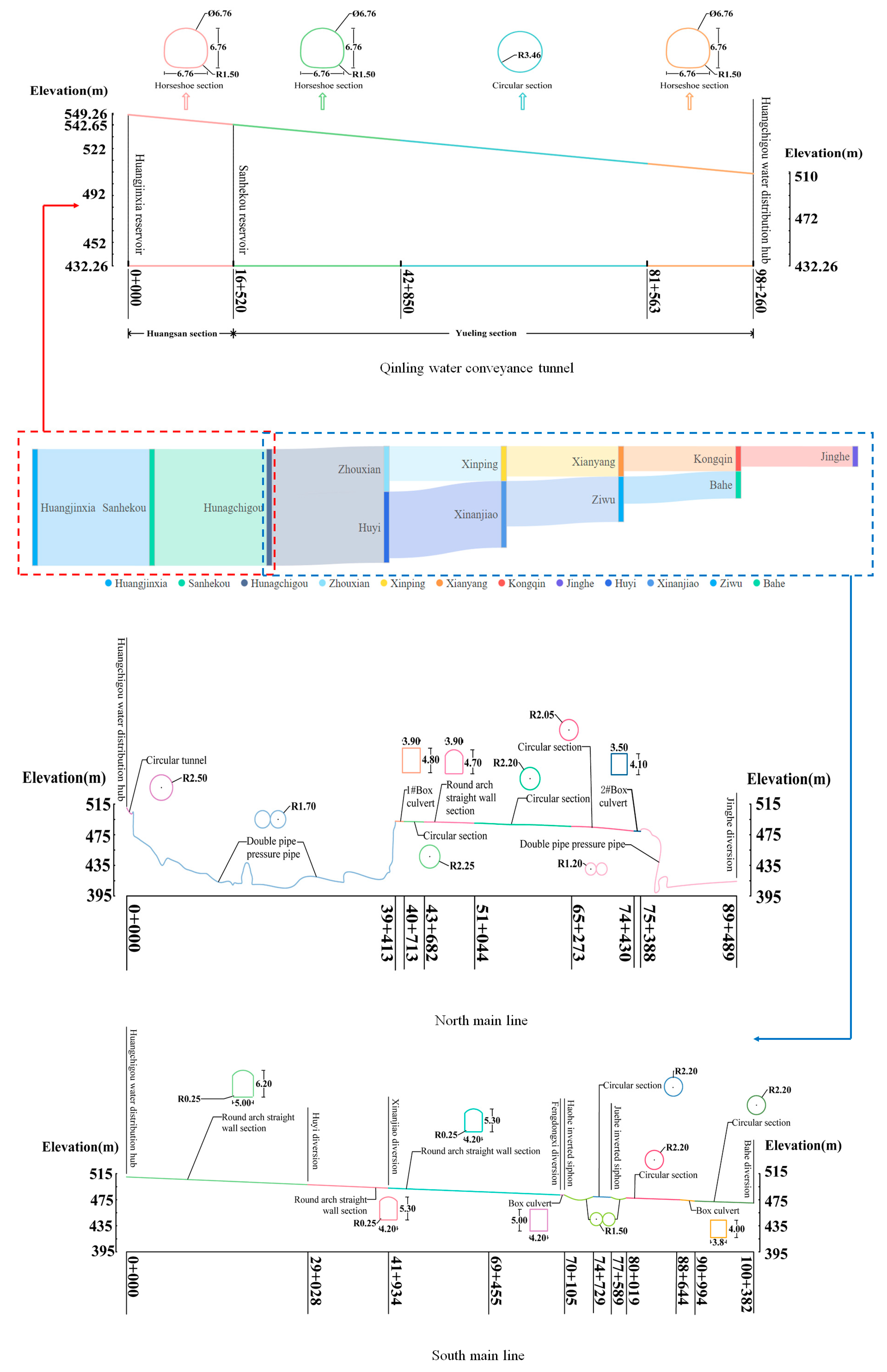
The flow rates, elevations, and profile distributions for each node are depicted in Figure 2, with flow values representing the design values for each pipeline segment. Through collaborative operation among the nodes, the water conveyance and distribution tasks were effectively fulfilled.

2.2. Forward Flow Routing Model

The MIKE11 advection–dispersion module (MIKE11 AD) holds significance within the MIKE11 model, serving as a crucial tool for simulating the convection and diffusion processes of soluble and suspended substances in water bodies [23,24,25,26,27]. Its application scope encompasses simulating both conservative and non-conservative substances. Concerning conservative substances, the module focuses solely on simulating their migration processes within the water body. Conversely, for non-conservative substances, the module enables the simulation of concentration changes over time by assuming a constant decay constant.
The MIKE11 AD module is established upon the hydrodynamic conditions furnished by the MIKE11 HD module. Therefore, utilizing the MIKE11 AD module for simulation necessitates the prior establishment of the MIKE11 HD module, followed by the definition of various parameter files and water quality boundary conditions within the AD module. The computations entail combining the hydrodynamic conditions provided by the HD module and applying advection–dispersion equations. This integrated approach yields accurate results for advection–dispersion simulations. The MIKE11 HD module is modeled based on the one-dimensional unsteady flow Saint-Venant equations. Its fundamental equations encompass the continuity equation and the momentum equation, articulated as follows:
Q x + Q t = q
Q t + ( α Q 2 A ) x + g A h x + g Q | Q | C 2 A R = 0
where Q is the flow rate; t is the time coordinate; A is the water cross-sectional area; x is the distance coordinate; q is the side inflow flow rate; g is the gravity acceleration; h is the water level; R is the hydraulic radius; C is the Chezy coefficient; α is the momentum correction coefficient.
At the same time, the AD module applies the advection–dispersion equation for calculations. The one-dimensional advection–dispersion equation is as follows:
A C t + Q C x x ( A D C x ) = A K C + C 2 q
where x is the distance coordinate; t is the time coordinate; C is the substance concentration; A is the water cross-sectional area; D is the longitudinal diffusion coefficient of the river channel; Q is the flow rate; K is the pollutant linear attenuation coefficient; and C2 is the pollutant source and sink concentration.
Due to the alternation between unpressurized and pressurized pipelines along the north–south main lines within the water transportation network, a transition phenomenon occurs when water flows through the network [28,29,30,31]. This transition, shifting between unpressurized open flow and pressurized full flow, brings significant changes in propagation speed. Simple hydraulic methods or the utilization of MIKE alone fail to capture the intricate routing processes within the entire water pipeline network. Numerical simulation methods addressing the transition process from a mixed free-surface-pressure flow typically include approaches like the shock wave fitting method, rigid water body method, and the Preissmann virtual narrow gap method [32,33,34,35]. While the shock wave fitting and rigid water body methods are employed, they exhibit drawbacks such as instability, intricate computational processes, and excessive computation outcomes. Conversely, the Preissmann virtual narrow gap method stands out for its stability, efficiency, and wide application in numerically simulating alternating open and full flow within water pipeline networks [36]. Leveraging the characteristics of the north–south main water transmission pipeline network, this paper adopts the Preissmann virtual narrow gap method. This method generalizes the pressurized pipelines within the water transmission network, simplifying the transition process between pressurized and unpressurized water transportation. By treating a pressurized pipeline as a pressureless conduit, it enhances the smoothness of pipeline connections and establishes a structural foundation for facilitating flow routing simulation.
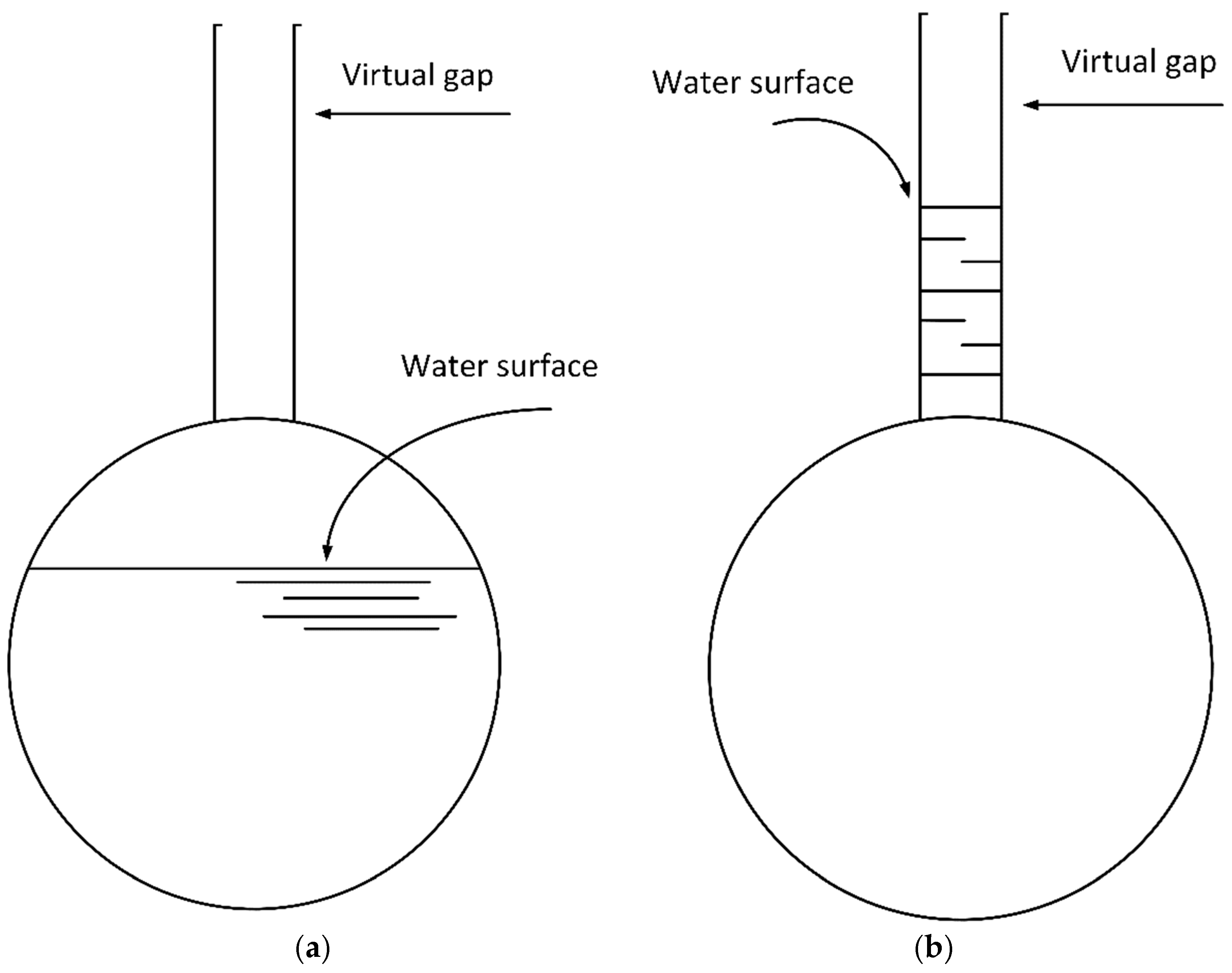
The depiction in Figure 3 illustrates the Preissmann virtual narrow gap method, which posits the existence of a prolonged and narrow opening atop the pressurized water tunnel. Remarkably, this gap does not modify the hydraulic radius or cross-sectional area of the pressurized pipe. Consequently, the volume of overflow water within this narrow gap does not interfere with the customary flow routing process. During stable water transport, the elevation difference from the pressurized pipe’s apex to the virtual narrow gap water line is considered as the head of the pressurized pipe. By integrating the concept of the virtual narrow gap, the challenge of transitioning between pressurized and unpressurized pipes is resolved. Essentially, this unites the alternating process between open and full flows into an unpressurized water transportation process. Consequently, the model assimilates pressurized and unpressurized flows, treating them as a unified entity. Ultimately, this unified approach enables the solution of the pressureless flow Saint-Venant equations to be obtained. By amalgamating these two water delivery processes, simulation outcomes closely approximate actual scenarios, enhancing the accuracy and precision of calculation results. This integration also furnishes comprehensive flow routing information, facilitating the simulation of the entire water delivery network’s flow routing process. This unified simulation method provides a pivotal foundation for engineering decision-making and optimal design by offering comprehensive insights into the water delivery network’s flow dynamics.

2.3. Reverse Flow Routing Model

The Muskingum method stands out for its simplicity in principle, ease of calculation, and ability to yield calculation results that align well with actual requirements, rendering it one of the more frequently employed flood calculation methods today [37,38]. In flow routing, the downstream flow process is deduced from the upstream flow process, constituting the forward flow routing method. Conversely, inferring the upstream flow process from the downstream flow process involves transforming the Muskingum method’s formula—a technique termed the inverse algorithm or inverse calculation [39,40]. This paper introduces the Muskingum inversion model into the study of flow routing in primary canals within north–south main lines hosting multiple water diversions, after conducting a comprehensive analysis of existing research methods. Initially proposed by American scientist G.T. McCarthy in the 1840s, the Muskingum method serves as a common technique for flood flow routing and calculation of water flow routing in pipes and canals. This method, grounded in simplified Saint-Venant equations, employs water balance and the relationship between upstream and downstream storage and release to deduce downstream outflow based on upstream inflow. Renowned for its ease of calculation and high accuracy, the Muskingum method’s fundamental equation is as follows:
O i + 1 = C 0 I i + 1 + C 1 I i + C 2 O i
C 0 = 0.5 Δ t K x K K x + 0.5 Δ t
C 1 = 0.5 Δ t + K x K K x + 0.5 Δ t
C 2 = K K x 0.5 Δ t K K x + 0.5 Δ t
C 0 + C 1 + C 2 = 1
where O i , O i + 1 is the overflow flow rate at the downstream section at time i and i + 1; I i , I i + 1 is the overflow rate at the upstream section at times i and i + 1; C0, C1, and C2 are all calculation coefficients; Δ t is the calculation interval; K is the water flow routing time in the river section under steady flow conditions; x is the flow factor coefficients.
The equation mentioned above presents parameters that require determination, except for Δ t , which can be adjusted according to specific requirements. The Muskingum method involves deriving the water flow routing time K and the flow factor coefficients x . Previous studies mainly relied on trial-and-error methods for parameter estimation. Typically, researchers would hypothesize a value for x , insert it into the model for trial calculation, conduct iterations, compare results, and eventually deduce the values for K and x . However, this trial algorithm exhibited drawbacks such as extensive computations, low efficiency, instability, and a lack of iterative optimization capabilities. Hence, this paper employs the least squares method to address these limitations and solve the Muskingum parameters. By synthesizing the aforementioned methods, the expression obtained is as follows:
O i + 1 O i = C 0 ( I i + 1 O i ) + C 1 ( I i O i )
A = O i + 1 O i
B = I i + 1 O i
C = I i O i
A = C 0 B + C 1 C
The least squares method is used to solve the coefficients of the above two-dimensional linear equation, and each coefficient is transformed into the following:
C 0 = C 2 A B B C A C B 2 C 2 ( B C ) 2
C 1 = B 2 C B B C A B B 2 C 2 ( B C ) 2
The parameters A , B, and C can be derived from historical water transmission process data measured from the pipeline. However, the ongoing HTWDP, currently in its second phase of construction, has not yet commenced water operations, leading to a scarcity of actual measured water transmission data. To address this challenge, this paper employs the aforementioned forward flow routing simulation model through MIKE11 to simulate the water delivery process within the water transmission pipeline network under diverse operational scenarios. These simulated data serve as a substitute for actual water delivery data and play a crucial role in bridging the forward and reverse flow routing simulation models. This approach aims to resolve the inability to determine the parameters of the Muskingum method due to the absence of measured data. Following the acquisition of values for coefficients A , B, and C , the parameters C0, C1, and C2 are computed using Equations (14) and (15). Subsequently, the Muskingum equation is solved to obtain the final solution. This entire solving process is executed within a compiled MATLAB program. The utilization of the forward flow routing simulation model to simulate water delivery processes fills the data gap resulting from the project’s ongoing construction phase, allowing for parameter determination and the subsequent solution of the Muskingum equation, facilitating comprehensive analysis despite the absence of actual measured data. The utilization of the forward flow routing simulation model to simulate water delivery processes fills the data gap resulting from the project’s ongoing construction phase, allowing for the parameter determination and subsequent solution of the Muskingum equation, and facilitating comprehensive analysis despite the absence of actual measured data.
The Muskingum method traditionally deduces downstream overflow flow based on the overflow flow of the upstream section. However, this paper aims to infer the water flow dynamics within the water conservancy project of the water transfer area using the water demand flow process of each water diversion in the water-receiving area. To achieve this objective, the Muskingum inverse method is introduced. In constructing the reverse flow routing simulation model, the Equation method is utilized. Its fundamental equation is derived from Equation (4) through a conversion process:
I i + 1 = O i + 1 C 1 I i C 2 O i C 0
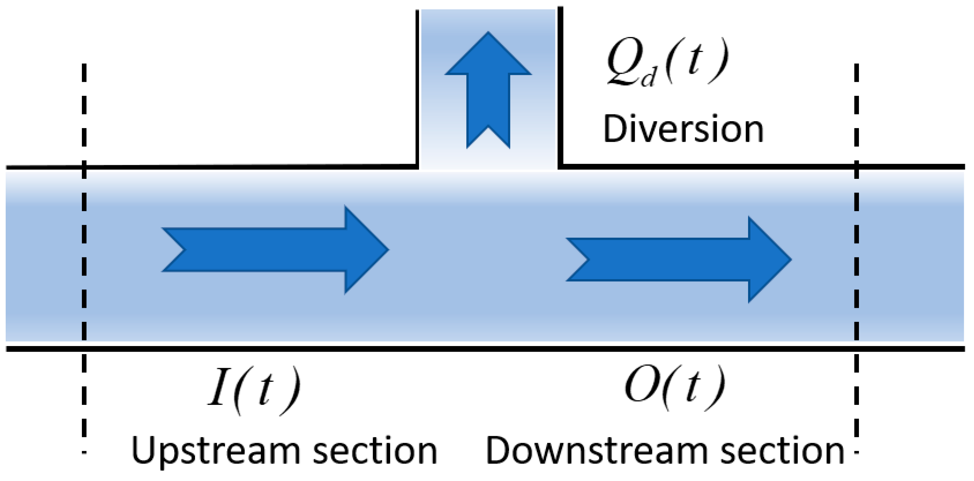
Owing to the intricate interplay between the outlet flow and individual pipe sections, employing the aforementioned formula directly to deduce the downflow process in water conservancy projects would exacerbate the propensity for irregular and erroneous flow superpositions during calculations. This significantly compromises the accuracy of the final results. Hence, this paper adopts the “merge after calculation” approach within the flow routing concurrent with the tributary process. This strategy aims to mitigate errors stemming from the direct application of the Muskingum inversion method. Figure 4 illustrates the operational dynamics of water flow within the water conveyance system.
The primary focus of this paper revolves around examining the water flow routing process specifically concerning water extraction from water diversions. Consequently, to streamline the model’s calculation process, factors such as evaporation, seepage loss, and water withdrawal within the water delivery pipe network are not taken into account. Within the “merge after calculation” methodology, the reverse routing simulation model of flow is initially employed to deduce the flow routing of the upstream section based on the downstream section’s flow dynamics. This, combined with the water intake flow processes from each water diversion, culminates in the determination of the inflow flow process of the upstream section.
I ( t ) = f [ O ( t ) ] + Q d ( t )
where I is the inflow flow process of the upstream section, O is the outflow flow process of the downstream section, Q d is the water intake flow process of the water diversions, and t is the calculation period.

2.4. Evaluation Methodology

This study employs the Kling–Gupta Efficiency (KGE) coefficient for the parameter calibration and performance assessment of the flow routing model. KGE measures the Euclidean distance from a point to the optimal point, incorporating the Correlation Coefficient (CC), Bias Ratio (BR), and Relative Variability (RV). The magnitude of KGE reflects the fitting between simulated and calculated values, with a value closer to 1 indicating a higher modeling accuracy. The calculation formula is as follows:
K G E = 1 ( C C 1 ) 2 + ( B R 1 ) 2 + ( R V 1 ) 2
C C = c o v ( Q s , Q c ) σ Q s σ Q c
B R = Q s ¯ / Q c ¯
R V = ( σ Q s / Q s ¯ ) / ( σ Q c / Q c ¯ )
where Q s is the simulated values, Q c is the calculated values, Q s ¯ is the average simulated values, Q c ¯ is the average calculated values.

2.5. Boundary Conditions

Both the Muskingum method and the Muskingum inversion method rely on measured flow data to derive the flow routing at each section within the model. However, in the case of the HTWDP, which comprises the Qinling water conveyance tunnel and the water conveyance pipe network in the water receiving area, the construction of each pipeline is currently in the second phase and has not been officially operational. This absence of measured flow rate data poses a challenge. To address this, this paper employs a forward flow routing simulation model and customizes water inflow processes as inputs to simulate the water flow routing processes in the Qinling water conveyance tunnel and the north–south main line, respectively. These simulations serve as the surrogate data for the measured overflow flow, subsequently used for parameter calibration within the Muskingum method. The resultant parameters obtained are also employed for the Muskingum inversion method, facilitating reverse flow routing simulation. It is important to note that the water diversion area of the HTWDP system is a composite of the Huangjinxia and the Sanhekou reservoirs. This area possesses intricate hydraulic connections and closely interlinked operational relationships. Together, they orchestrate the dispatch of the water volume for the IWTP. Consequently, attempting to individually reverse-invert the water demand flow in the water receiving area would disrupt the internal system connections, impeding the synergy and unique advantages of each project from being fully leveraged. Given these considerations, this paper treats the water conservancy project in the water diversion area as a unified entity. The endpoint for reversing the inversion of the water demand flow is set at the Huangjinxia reservoir.
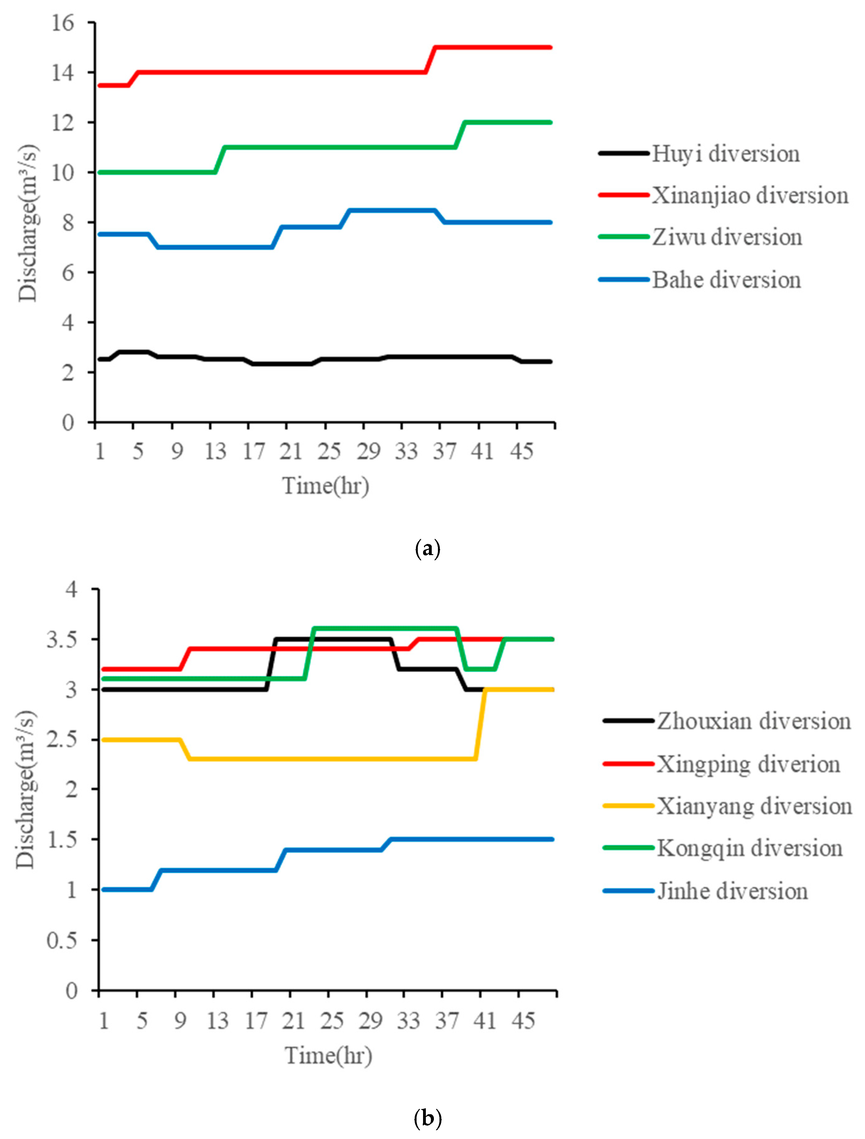
Moreover, the water delivery mechanisms of both the Qinling water conveyance tunnel and the north–south main line exhibit a relatively independent nature. Consequently, this paper employs distinct water inflow processes for each water delivery component as input. Simultaneously, the water demand processes for each branch of the north–south main line are customized, interlinking the water inflow processes of each component with the water demand processes of the water diversions. Figure 5 and Figure 6 depict the correlation between the water inflow processes of the water delivery objects and the water demand processes of the water diversions.
To ensure the fluency and accuracy of the simulation, all parts of the simulation were conducted under hot start conditions, that is, the initial moment was a stable water delivery state, and each flow process did not exceed the corresponding design flow value.
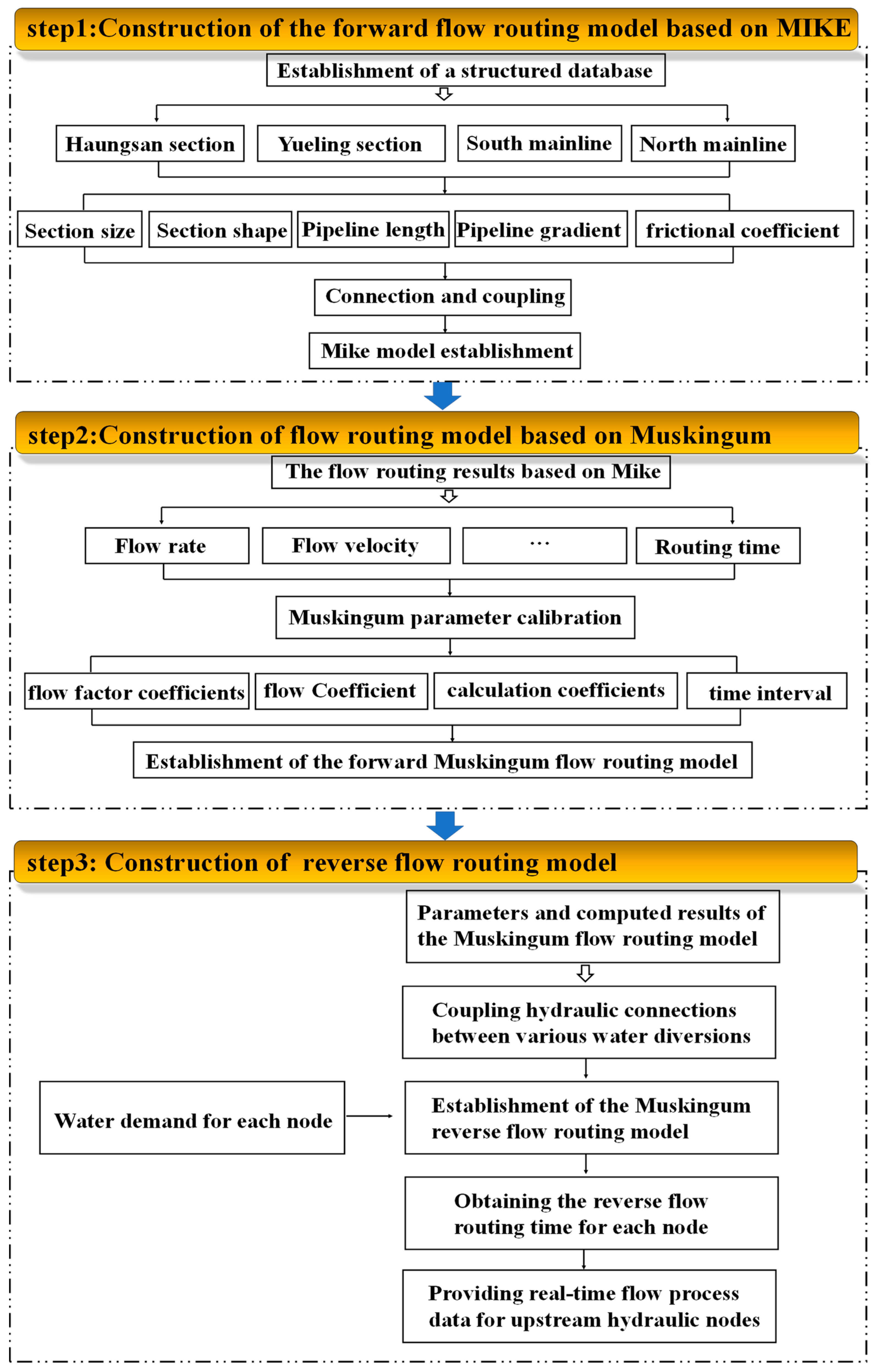
The entire simulation process of IWTP reported in this paper mainly consists of three parts, namely:
(1)
Construction of the forward flow routing model based on MIKE.
(2)
Construction of the flow routing model based on Muskingum.
(3)
Construction of the reverse flow routing model
The process of simulating flow routing for proposed and under-construction hydraulic engineering projects often faces challenges due to the lack of historical runoff data for reference. Consequently, the application of the Muskingum method for simulating flow routing becomes impractical. To address this issue, this paper initially focuses on constructing structured databases for the various nodes of the projects. Key parameters include section shape, section size, pipeline length, pipeline gradient, and frictional coefficients. Following this, the Preissmann virtual narrow gap method is utilized to establish connections and couplings between the structural elements of each node, effectively resolving issues related to mixed free-surface-pressure flow within the pipelines. Subsequently, a comprehensive flow routing model is constructed based on MIKE, allowing for the calculation of flow characteristics such as flow rate, velocity, and routing time. The Muskingum parameters are then calibrated, incorporating factors such as flow factor coefficients, flow coefficients, calculation coefficients, and time intervals, facilitating the development of Muskingum flow routing models. Finally, based on the parameters and computed results of the forward Muskingum flow routing model, hydraulic connections between various water diversions are coupled to establish the Muskingum reverse flow routing model. This model enables the simulation of reverse flow routing at each node, providing real-time water demand processes for upstream hydraulic nodes. These processes facilitate the formulation of rational operation schemes, thereby enabling real-time operation for IWTPs.
Through hierarchical embedding and coupling, these three main processes collectively form a comprehensive system for simulating flow routing throughout the entire IWTP. By addressing challenges related to the lack of historical data and utilizing advanced methodologies such as the Prinsen and Muskingum methods, this approach lays a solid theoretical foundation for the real-time operation of IWTP, even in scenarios involving multiple water diversions. The entire process of the flow routing simulation for the IWTP is illustrated in Figure 7.

3. Results and Discussion

3.1. Full Process of Forward Flow Routing

In a state of equilibrium, the temporal routing characteristics of each pipe section exhibit distinct behaviors under varying water delivery rates. Specifically, within the Qinling water conveyance tunnel, the third Huang section and the cross-ridge section demonstrate similar parameters such as roughness and slope ratio, allowing for a holistic treatment. Water is pumped from the Huangjinxia reservoir pumping station to the outlet, gradually escalating from 1 m3/s to the designated capacity of the Qinling water conveyance tunnel, set at 70 m3/s. Consequently, we conducted calculations to determine the routing time for water masses exhibiting high concentrations of conservative substances, originating from the Huangsan section and Yueling section and moving towards Huangchigou, across various flow rates.
Unlike the relatively uniform structure of the Qinling water conveyance tunnel, the north–south main line within the water-receiving area boasts a more intricate pipeline composition and interconnections among pipe sections. Both the south main line and the north main line progressively augment their water delivery rates to achieve a steady state. Simultaneously, they fine-tune the water intake flow at the water diversions, ensuring that downstream water pipeline sections do not surpass their maximum design flow thresholds. To simulate and compute the flow routing process under varying water delivery flow conditions, this study utilized both the hydrodynamic module and the advection–dispersion module.
To achieve the water delivery process in a stable equilibrium, this study employed the hot start method, leveraging prior calculation outcomes as a basis. Through a gradual escalation of discharge flow from Huangchigou and corresponding adjustments in water intake at the water divider, we determined the routing time for various pipe sections under different water transfer flows. Additionally, a more comprehensive analysis involved calculating the duration for conservative materials to transit from Huangchigou to each key section, thus furnishing more comprehensive routing time information.
Specifically focusing on the south main line, the design flow within each pipe section gradually diminishes from upstream to downstream. Initially, the water diversion of the south main line is closed, and the flow rate is incrementally increased until reaching the maximum design flow rate at the Bahe section. Within the HD module, this study utilizes the resultant flow rate as the parameter file representing the initial condition. Subsequently, it derives the hydrodynamic result file via simulation calculations, serving as a reference file for the hot start in the subsequent flow conditions, thus facilitating the recalculation of the water output in the steady state. Moreover, within the AD module, the corresponding flow rate is also employed as the parameter file. Subsequent stable water delivery conditions automatically overwrite the previous result file, ensuring an updated representation of the ongoing conditions.
Taking the south main line as an example, when Huangchigou discharges at a flow rate of 19 m3/s, the water intake flow rate at the Ziwu water diversion is 1 m3/s. At this juncture, the water delivery flow rate from Ziwu to the Bahe section attains the designated value of 18 m3/s. Subsequently, the flow rate is incrementally increased, and as each pipe section reaches its design flow value, the water intake from the preceding diversion escalates accordingly. This routing continues until the discharge flow of Huangchigou reaches 47 m3/s. At this stage, the water intake flow at the Huyi water diversion reaches 3 m3/s, while maintaining unchanged water intake flow rates at other water diversions. Similarly, the flow routing in the north main line follows a gradual increase in water delivery flow, ensuring adherence to the maximum design flow within downstream water delivery pipe sections.
Analyzing the duration required for a high-concentration water mass of conservative substances to transit from Huangchigou to key sections under various stable flow conditions allows us to ascertain the routing time across different pipe sections at distinct water delivery flows. This analysis serves as a crucial reference point for investigating the stability and optimization of water delivery systems.
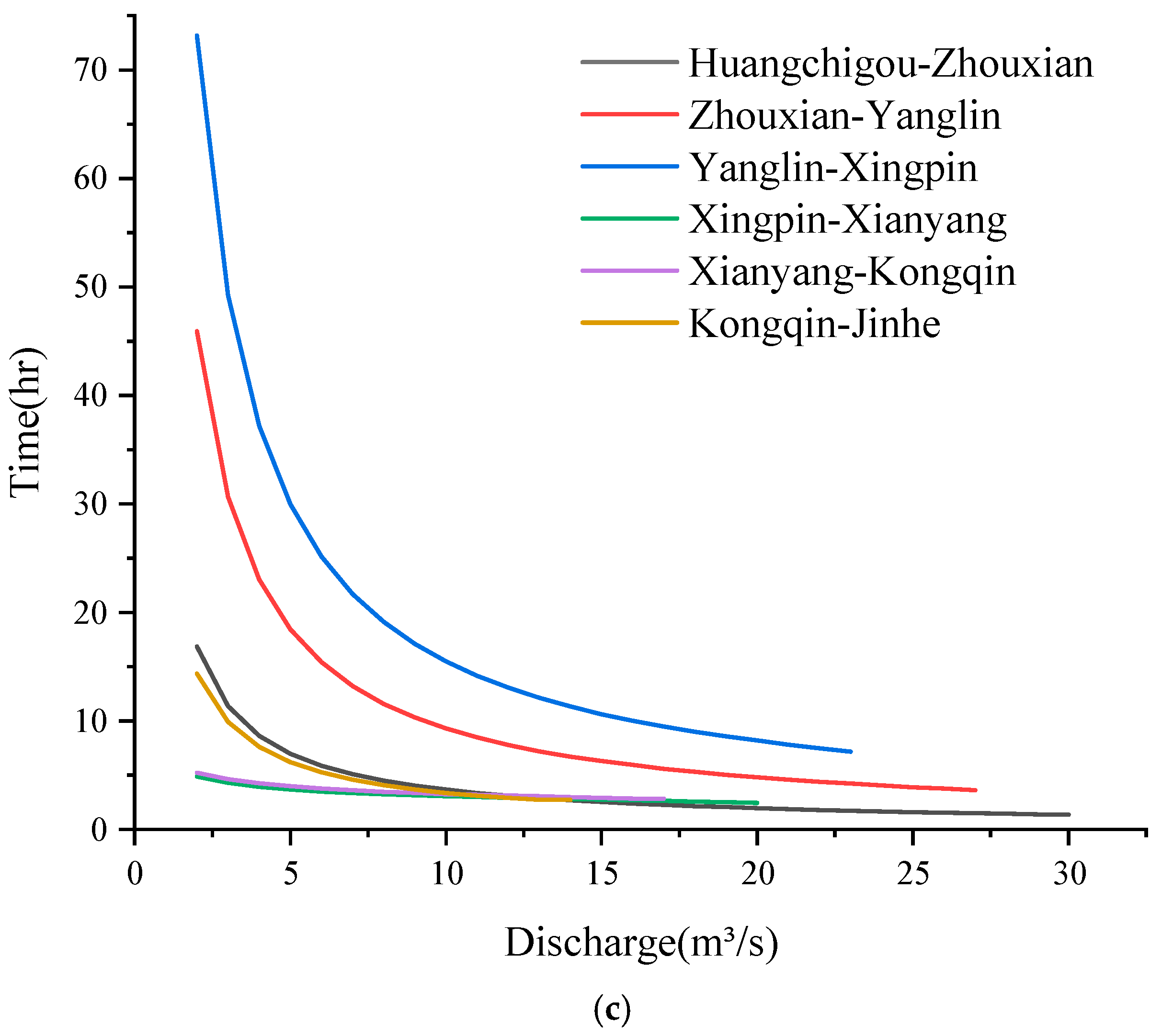
Figure 8 illustrates a consistent overall trend in flow routing across all pipe sections. Notably, the routing time of water flow in each section gradually decreases with increasing water delivery flow. These simulation results align with hydraulic principles and mirror actual engineering conditions. In the context of the Qinling water conveyance tunnel, the relatively short water conveyance distance in the Huangsan section, spanning a total length of 16.52 km, results in less susceptibility to changes in flow rates. Here, the relationship between flow rate and routing time approximates linearity. Treating Huangjinxia and Sanhekou as an integrated operational unit minimizes the impact of the Huangsan section’s routing process on the entire system’s operation. Conversely, the cross-ridge section, characterized by a longer water transport distance, exhibits a noticeable decline in routing time as flow rates gradually increase. With further augmentation in flow rates, the impact of water flow attenuation causes a continual decrease in routing time, albeit at a decelerating rate. The combined water transport processes of the Huangsan and Yueling sections define the flow routing dynamics within the Qinling water conveyance tunnel. At a flow rate of 70 m3/s, the shortest observed flow routing time stands at 12.78 h.
The north–south main water transmission pipelines span vast distances and feature diverse pipe types due to varying topographical and landform disparities. Consequently, their connection methods exhibit significant diversity, further compounded by the intricate interplay of pressure and no-pressure conditions within the pipeline network. These complexities give rise to distinctly different internal flow routing processes within each pipe section. Under stable water delivery conditions, the south main line discharges 43 m3/s from Huangchigou, necessitating 15.85 h to reach the Bahe water diversion endpoint. Similarly, with a discharge rate of 30 m3/s from Huangchigou, the main line requires 20.15 h to reach the Jinghe water diversion. Notably, the Ziwu to Bahe section of the south main line spans 34.2 km, comprising an inverted siphon, tunnel, and aqueduct. This segment is notably influenced by the hydraulic characteristics of pressurized pipelines, exhibiting a rapid response to changes in flow rate. Once the flow rate surpasses 9 m3/s, the flow routing time’s responsiveness diminishes due to the water flow attenuation effect. Conversely, the Huyi to southwest suburbs section, totaling 11.9 km and composed primarily of water conveyance tunnels, exhibits a flow rate–time relationship curve akin to that of the Huangsan section, thereby validating the simulation results’ credibility. Similarly, within the north main line, the Yangling to Xingping section stands out with a length of 24 km and primarily comprises pressure pipes, box culverts, and tunnels. This section demonstrates the most rapid response to flow routing time, with a noticeable slowdown in growth rate once the flow rate exceeds 8 m3/s.
It is evident that the flow routing processes within the Qinling water conveyance tunnel and the north–south water conveyance main line play an integral role in the dispatch system when water users within the HTWDP’s water-receiving areas articulate more refined operational requisites for the system. The time lag effect inherent in water flow within the water transmission network significantly influences hourly dispatch decisions. Hence, deducing real-time water demand processes on the water transfer side through a reverse flow routing simulation becomes imperative, serving as a foundational dataset to facilitate refined dispatch strategies.

3.2. Full Process of Reverse Flow Routing

The Muskingum method, historically reliant on available runoff data, involves model parameter calibration and simulation of the water flow routing process to analyze cross-sectional runoff. Previous scholarly works have extensively explored this method [41,42,43]. However, the project under study in this paper is currently under construction and lacks access to historical runoff data. Consequently, this study utilized a forward water flow routing simulation to derive the runoff process as the foundational dataset in the preceding section. Subsequently, reverse routing simulations were conducted for further analysis.
(1)
Forward flow routing simulation and Muskingum parameter calibration
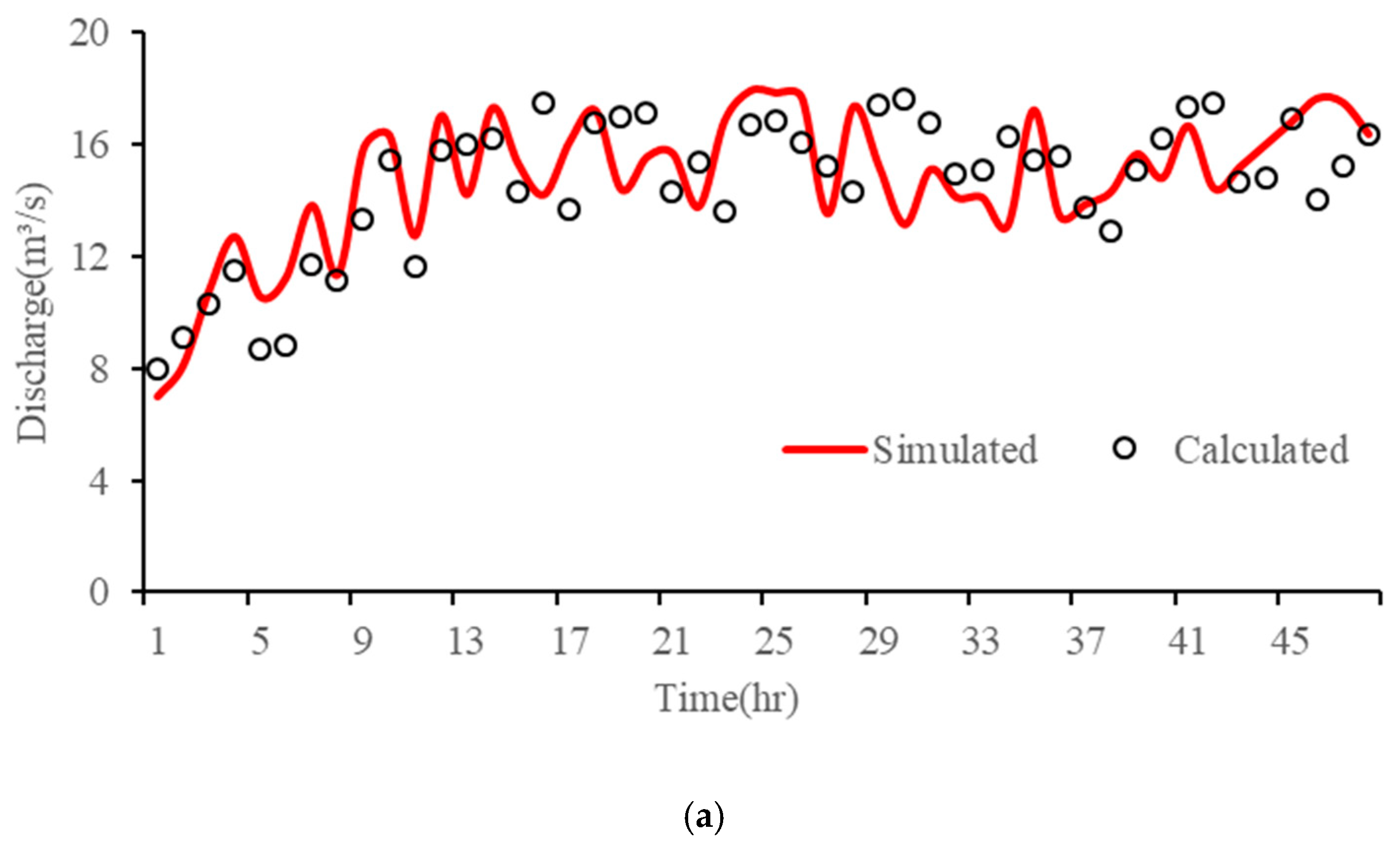
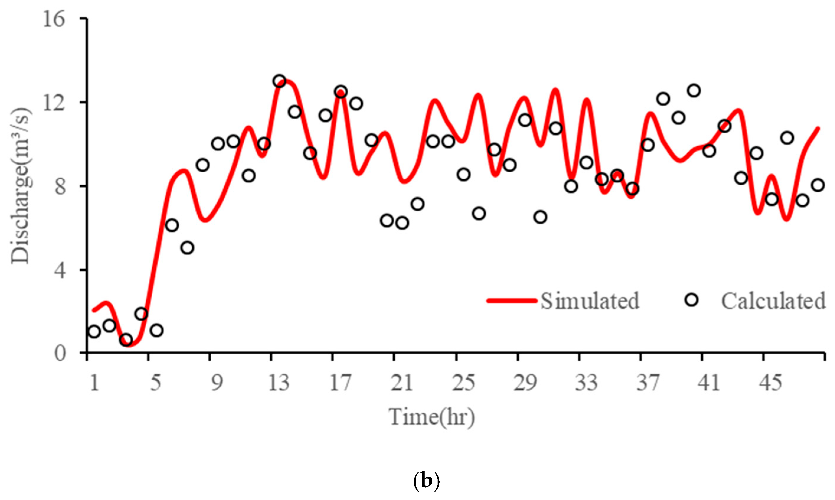
In the forward flow routing model of this study, the Preissmann virtual narrow gap method was employed to address the issue of a mixed free-surface-pressure flow in water conveyance pipe networks. To further validate the rationality and effectiveness of this method, the study initially explored the scenario without utilizing the Preissmann virtual narrow gap method. In this regard, each node’s inflow process was predefined, and numerical simulations were conducted using the forward flow routing model to obtain the flow processes at the tail sections of each node. Since the Qinling water conveyance tunnel is an unpressurized pipeline throughout, unaffected by the mixed free-surface-pressure flow, it is not considered here, and the discussion is focused solely on the north and south main lines. The results, as shown in Figure 9, illustrate the flow processes at the tail sections of the north–south water conveyance main line derived from the forward flow routing model (highlighted in red). Both exhibit an initial upward trend followed by significant fluctuations within a certain range. The fluctuation process appears as a sawtooth-like alternation, with the North main line displaying more pronounced fluctuations due to more frequent mixed free-surface-pressure flows compared to the south main line. Using these simulation results as input, the Muskingum forward routing method was subsequently employed to calculate the flow processes at the tail sections of the north–south water conveyance main line. The calculated results (highlighted in black) generally followed the trend of the simulated flow processes but exhibited a higher overall dispersion, resulting in a poorer fit with the simulated values. The average errors for the south and north mains were 1.12 m3/s and 1.72 m3/s, respectively, with maximum errors of 4.51 m3/s and 5.63 m3/s. It is evident that the substantial errors may significantly impact the subsequent simulation of the reverse flow routing.
Building upon this, to further explore the feasibility of a subsequent reverse flow routing simulation, the study proceeded by utilizing the Preissmann virtual narrow gap method. Subsequently, the forward flow routing model was employed to simulate the water flow processes at the tail sections of the nodes, allowing for a comparative analysis. As illustrated in the simulation values (highlighted in red) presented in Figure 10, upon comparing the flow dynamics between the inlet section (Figure 5) and the tail section of each project, it is evident that the inlet section experiences more pronounced flow fluctuations. Over the course of long-distance water transportation, the influence of the water flow evolution’s smoothing effect reduces the fluctuation of the flow process at the tail section. Concurrently, at the tail section of the north–south main line, there is a significant reduction in flow due to varying water intake from multiple water outlets. This trend aligns closely with the actual operational norms governing the project.
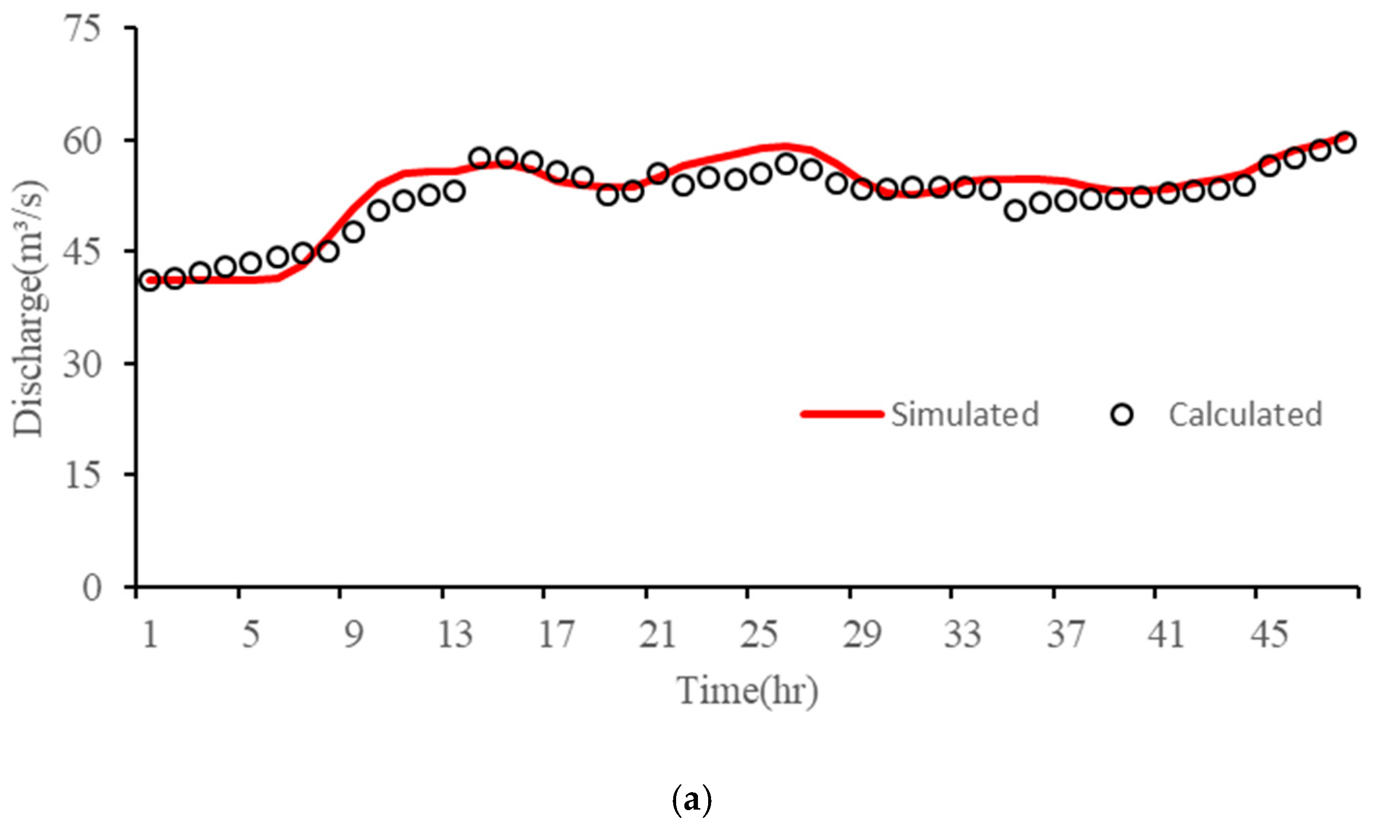
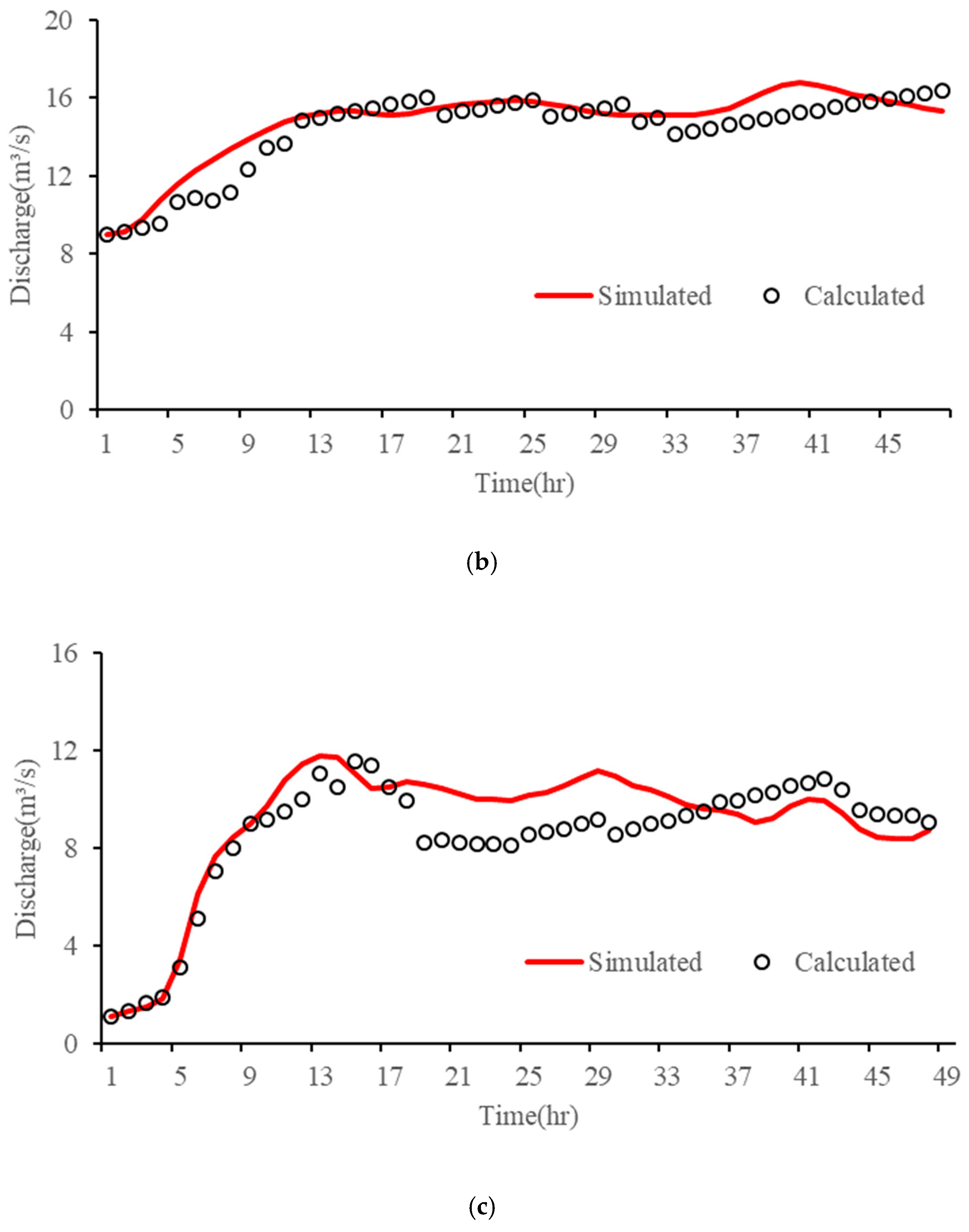
Additionally, as depicted in Figure 10, the trends exhibited in the calculated flow processes align relatively well with the simulated flow processes at the tail sections of each node. Both show a gradual increase followed by a tendency to plateau. Notably, the Qinling water conveyance tunnel, due to its higher flow rate, generates a larger average error of 0.91 m3/s, with a maximum error of 3.84 m3/s. In comparison, the average errors for the south and north mains are 0.45 m3/s and 0.51 m3/s, representing a reduction of 59.82% and 70.35%, respectively, compared to not using the Preissmann virtual narrow gap. The maximum errors for the north–south water conveyance main line are 1.85 m3/s and 2.39 m3/s, reflecting a decrease of 58.98% and 57.55%, respectively, compared to not using the Preissmann virtual narrow gap method. These results indicate that the calculated outcomes possess a high level of accuracy and reasonability.
Therefore, it is evident that with the incorporation of the Preissmann virtual narrow gap method, the model’s simulation accuracy significantly improves, providing a solid data foundation for subsequent simulations of reverse flow routing. After Muskingum parameter calibration, these calibrated parameters can effectively be applied to the subsequent reverse flow calculations. Table 1 summarizes the calibration results for each project Muskingum parameter.
To further validate the accuracy of the flow routing model, this study calculated and compares the KGE for the model results before and after employing the Preissmann virtual narrow gap method. The results are presented in Table 2 below.
As mentioned above, since the Qinling water conveyance tunnel is an unpressurized pipeline and does not generate mixed free-surface-pressure flow, different models do not impact the results for this node. Therefore, this paper does not repeat the calculations for this section, but the results are presented using the Preissmann virtual narrow gap method (Preissmann). The KGE indices for the Qinling water conveyance tunnel, south main line, and north main line were 0.76, 0.73, and 0.65, respectively, all exceeding 0.5, indicating the reasonability of the model. The Qinling water conveyance tunnel and south main line, with relatively simple structures, exhibited a higher fitting accuracy. Meanwhile, in the model results obtained without using the Preissmann virtual narrow gap method (non-Preissmann), the KGE indices for the south and north main lines were 0.38 and 0.27, respectively. The lower indices suggest poor model fitting accuracy, making the results unreliable and unsuitable for subsequent research. This further demonstrates that the adoption of the Preissmann virtual narrow gap method to address the mixed free-surface-pressure flow issue is essential for constructing complex water conveyance network models and effectively improves the model’s fitting accuracy.
(2)
Reverse flow routing simulation and comparative analysis
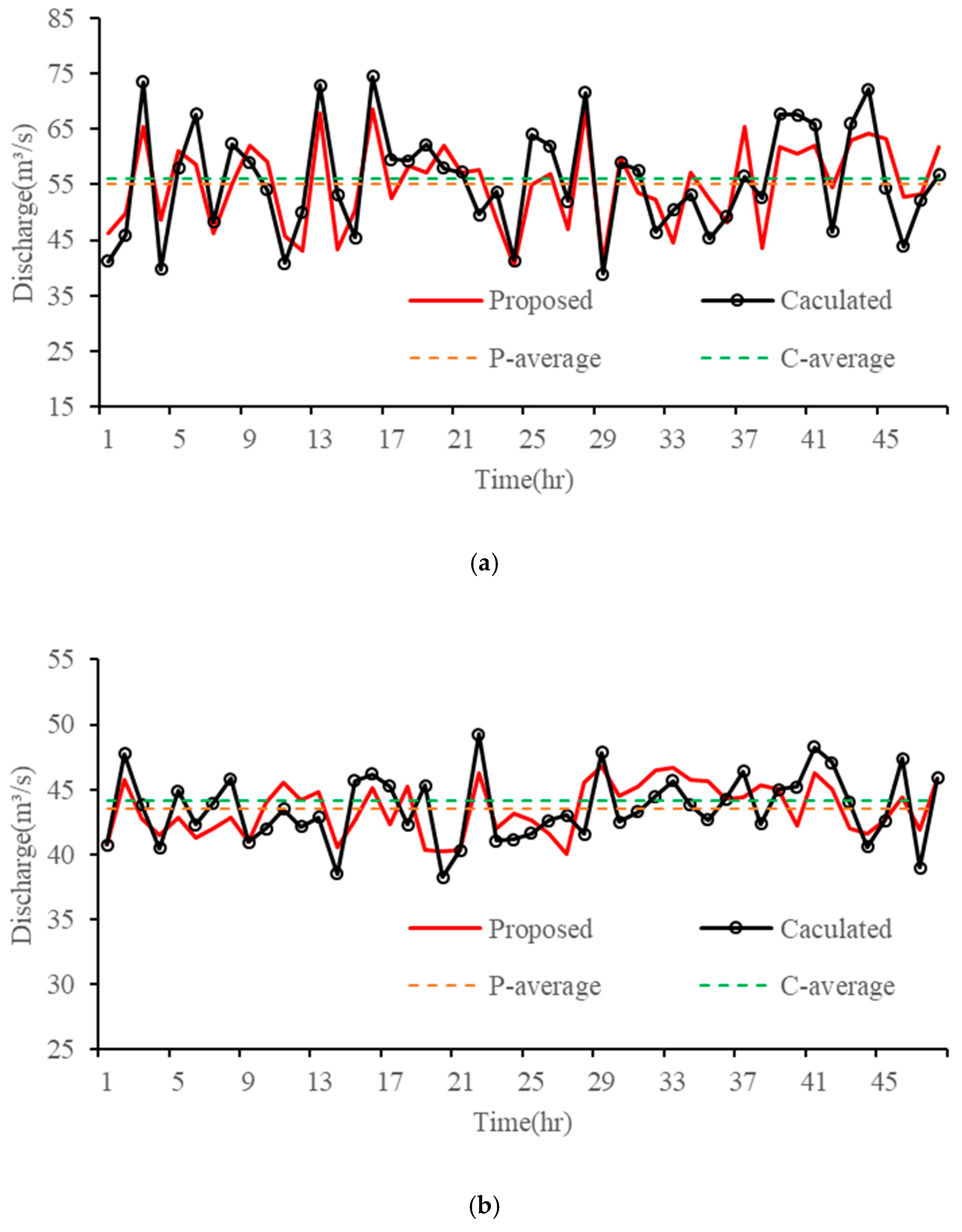
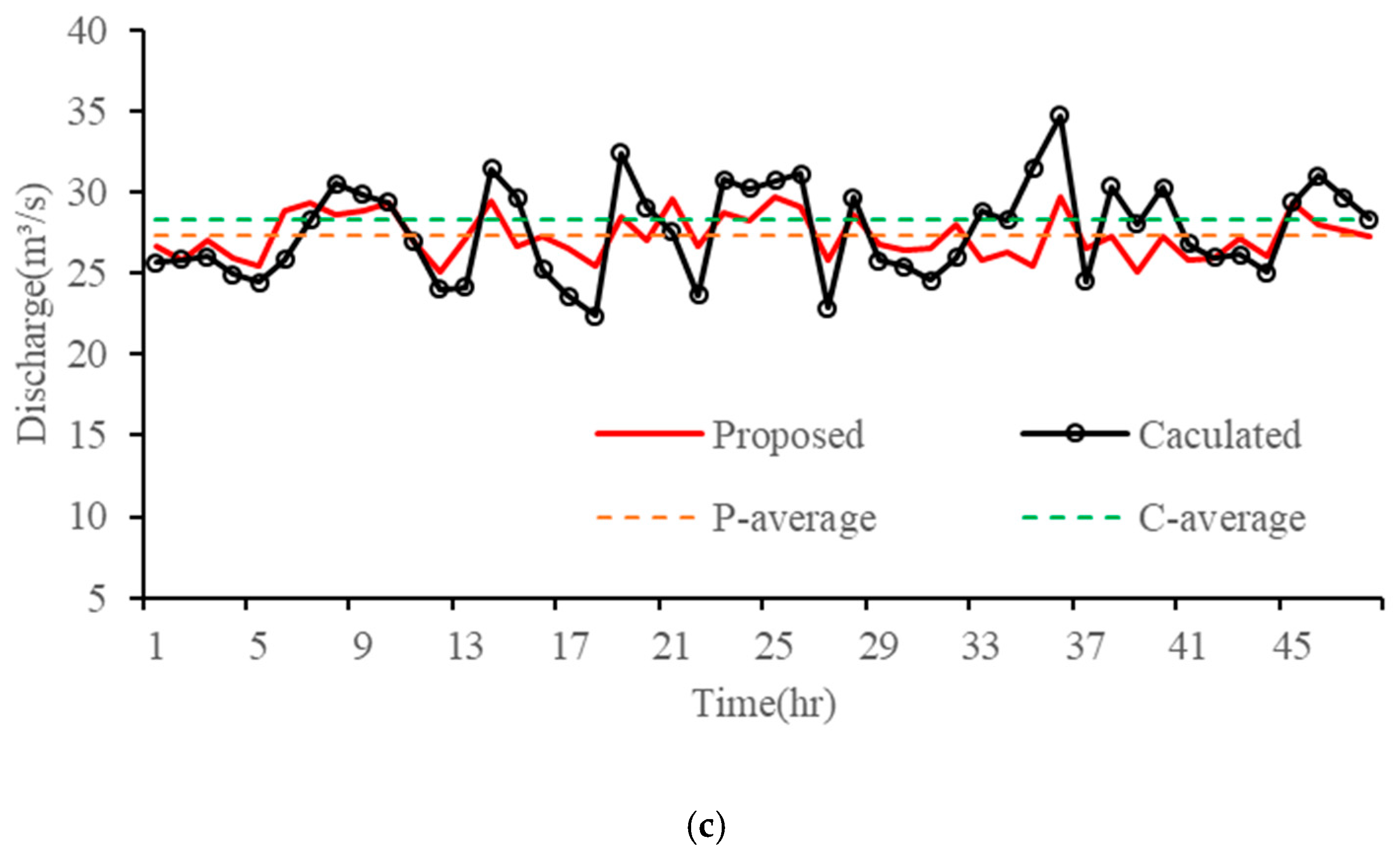
The Muskingum inversion model, derived using the aforementioned parameters, entails jagged phenomena and alternating positive and negative values during the flow inversion calculation process. To address this, this study combined the Bisection method [44,45] with the “merge after calculation” method mentioned earlier to simulate the reverse flow routing for each project. The resulting flow processes of each inflow section are illustrated in Figure 11. The disparities between the proposed inflow values of the Qinling water conveyance tunnel and the north–south main line and their respective inversion values are small, demonstrating an overall agreement in fluctuation trends. Specifically, the differences between the proposed average values and the inverted average values are 0.98 m3/s, 0.63 m3/s, and 0.94 m3/s for the Qinling water conveyance tunnel, south main line, and north main line, respectively. These average values are presented in Table 3.
At the entrance section of the Qinling water conveyance tunnel, the proposed flow process (Figure 5) exhibits notable oscillations, and the inversion results closely replicate this oscillatory trend, indicating the higher accuracy of the reverse flow routing model. Moreover, the relative error of the inflow remains within 5% for most periods. The maximum relative error observed in each flow process is 23.57%, occurring in the inflow of the north main line. The north main line water pipeline network presents a complex structure comprising tunnels, pressure pipes, boxes, culverts, inverted rainbows, and pipe bridges. Additionally, the presence of dual pipes in many water pipelines somewhat compromises the accuracy of reverse flow routing simulation results. The second phase of the north main line includes multiple water inlets, leading to continuously changing water intake processes that further interfere with the reverse routing process, intensifying jagged fluctuations in the water flow process. However, despite these challenges, the inflow inversion process of the north main line predominantly remains within a reasonably calculated range for most instances, displaying minimal differences from the proposed values. Therefore, it is still deemed applicable for simulating reverse flow routing within the northern main line.

4. Conclusions

This study comprehensively investigated the whole flow routing simulation system, culminating in the development of a cohesive framework by coupling and nesting the forward flow routing model with the reverse flow routing model. The MIKE11 model, integrated with the Preissmann virtual narrow gap method, was employed to execute forward flow routing simulations within the operational system. This approach adeptly addresses the mixed free-surface-pressure flow processes, unveiling the hydraulic characteristics of flow within the water pipeline network and elucidating the routing rules across each project. Furthermore, Muskingum’s inverse methods were leveraged for the simulation of reverse flow routing. The Bisection method, in conjunction with the “merge after calculation” technique, was employed to mitigate the volatility of inverse results, ensuring a more accurate depiction of the reverse flow process within the inlet section of each project. The principal conclusions derived from this study are as follows:
(1)
The comprehensive flow routing system for the entire HTWDP comprises two primary components: forward and reverse flow routing simulations. The forward flow routing simulation serves the dual purpose of generating simulation data for systems lacking historical flow data and operating as a crucial data input. It is intricately coupled and nested with the reverse flow routing simulation, enabling bidirectional flow routing simulations within the entire operational system.
(2)
In each pipe section, the flow routing time initially exhibits a noticeable decreasing trend with the rise in flow rate. However, the attenuation effect during prolonged water transportation gradually slows down this trend as the water flow rate further increases. Notably, pressurized pipelines demonstrate more pronounced flow rate changes and faster response speeds compared to unpressurized pipelines. Under their respective design flow conditions, the Qinling water conveyance tunnel exhibits the fastest routing time at 12.78 h, while the south and north main lines register 15.85 h and 20.15 h, respectively. Hence, the time lag effect inherent in long-distance water transportation cannot be underestimated, necessitating accurate simulation of flow routing throughout the entire process.
(3)
The influence of water intake at water diversions and the attenuation effect on water flow not only diminishes the flow rate at the tail section but also mitigates the volatility of the flow process. The complex and varied structures, coupled with the water intake process involving multiple water diversions, can impact the accuracy of flow inversion results. The use of the Preissmann virtual narrow gap method effectively addresses the issue of mixed free-surface-pressure flow in the water conveyance network. It significantly reduces the average errors between simulated and calculated values for the south and north main lines by 59.82% and 70.35%, respectively, greatly enhancing the fitting accuracy of the flow routing model. The KGE indices for each node in the model are all above 0.5. After parameter calibration, the overall trend of the flow processes at the entrance sections of each node, estimated using the Muskingum inverse method, closely aligns with the simulated process. The relative errors for most time periods are controlled within 5%, reflecting the accuracy of the model. This provides a theoretical foundation for achieving a refined IWTP operation in the future.
It is noteworthy that this study effectively addressed the issue of a mixed free-surface-pressure flow within the pipeline network using the Preissmann virtual narrow gap method. By constructing a flow routing model based on MIKE, it resolved the challenge of lacking historical flow data for proposed or ongoing water transfer projects. Furthermore, it provided a data foundation for establishing the Muskingum flow routing model. After parameter calibration and scheme comparison, a reverse flow routing model was developed using the Muskingum reverse routing method. Through computation, real-time flow processes for the upstream of the project, namely, real-time water demand processes for the receiving area, were obtained. By coupling all the aforementioned research processes, a comprehensive IWTP flow routing simulation system was ultimately established. Consequently, it enabled a real-time operation for IWTPs, potentially enhancing the management and operational efficiency of such projects.
However, this study encountered certain limitations. Primarily, due to the constraints imposed by the completeness of engineering data, the simulation was confined to the evolution process of existing data within the engineering project. The absence of data presented challenges and added complexity to the research. Additionally, the intricate nature of engineering structures significantly impacted the accuracy of the simulation results. Therefore, acquiring more comprehensive engineering data in future research endeavors is an imperative to rectify and enhance the model’s simulation accuracy.

Author Contributions

X.Y.: Methodology, Conceptualization, Writing—original draft. Y.W.: Supervision, Writing—review and editing, Funding acquisition. Z.X.: Conceptualization, Review. M.H.: Methodology, Investigation. All authors have read and agreed to the published version of the manuscript.

Funding

This study was supported by the Basic Research Plan of Natural Science in Shaanxi Province (Grant No. 2022JC-LHJJ-02) and the National Natural Science Foundation of China (Grant No. U2243233). The authors thank other researchers and institutions involved in the study.

Data Availability Statement

The original hydrological data used in the study were provided by a third party. Please contact the corresponding author for data.

Conflicts of Interest

The authors declare that they have no known competing financial interests or personal relationships that could influence the work reported in this paper.

References

  1. Roozbahani, A.; Ghased, H.; Shahedany, M.H. Inter-basin water transfer planning with grey COPRAS and fuzzy COPRAS techniques: A case study in Iranian Central Plateau. Sci. Total Environ. 2020, 726, 138499. [Google Scholar] [CrossRef]
  2. Zhou, Y.; Guo, S.; Hong, X.; Chang, F.J. Systematic impact assessment on inter-basin water transfer projects of the Hanjiang River Basin in China. J. Hydrol. 2017, 553, 584–595. [Google Scholar] [CrossRef]
  3. Yang, Y.; Chen, S.; Zhou, Y.; Ma, G.; Huang, W.; Zhu, Y. Method for quantitatively assessing the impact of an inter-basin water transfer project on ecological environment-power generation in a water supply region. J. Hydrol. 2023, 618, 129250. [Google Scholar] [CrossRef]
  4. Thomas, T.; Ghosh, N.C.; Sudheer, K.P. Optimal reservoir operation—A climate change adaptation strategy for Narmada basin in central India. J. Hydrol. 2021, 598, 126238. [Google Scholar] [CrossRef]
  5. Valerio, C.; Giuliani, M.; Castelletti, A.; Garrido, A.; De Stefano, L. Multi-objective optimal design of interbasin water transfers: The Tagus-Segura aqueduct (Spain). J. Hydrol. Reg. Stud. 2023, 46, 101339. [Google Scholar] [CrossRef]
  6. Ming, B.; Zhong, H.; Zhang, W.; Yang, G.; Zhao, Z.; Huang, Q. Deriving operating rules for inter-basin water transfer projects incorporating a scenario reduction strategy. J. Hydrol. 2023, 624, 129854. [Google Scholar] [CrossRef]
  7. Guo, Y.; Tian, X.; Fang, G.; Xu, Y.P. Many-objective optimization with improved shuffled frog leaping algorithm for inter-basin water transfers. Adv. Water Resour. 2020, 138, 103531. [Google Scholar] [CrossRef]
  8. Sousa Estácio, Á.B.; Melo Rocha, M.A.; Caetano de Oliveira, M.; Oliveira da Silva, S.M.; de Souza Filho, F.D.A.; Marinho de Carvalho Studart, T. Priority of water allocation during drought periods: The case of Jaguaribe Metropolitan inter-basin water transfer in semiarid Brazil. Sustainability 2022, 14, 6876. [Google Scholar] [CrossRef]
  9. Gao, Y.; Liu, Y.; Gao, L.; Wu, M.; Intriago Gordillo, J.R.; Xue, Z.; Chen, S. Change of stream network connectivity under polder-type flood control measure. JAWRA J. Am. Water Resour. Assoc. 2023, 59, 701–725. [Google Scholar] [CrossRef]
  10. Lagos, M.S.; Muñoz, J.F.; Suárez, F.I.; Fuenzalida, M.J.; Yáñez-Morroni, G.; Sanzana, P. Investigating the effects of channelization in the Silala River: A review of the implementation of a coupled MIKE-11 and MIKE-SHE modeling system. Wiley Interdiscip. Rev. Water 2023, 2, e1673. [Google Scholar] [CrossRef]
  11. Yi, Y.; Tang, C.; Yang, Z.; Zhang, S.; Zhang, C. A one-dimensional hydrodynamic and water quality model for a water transfer project with multihydraulic structures. Math. Probl. Eng. 2017, 2017, 2656191. [Google Scholar] [CrossRef]
  12. Ren, H.; Tao, Y.; Wei, T.; Kang, B.; Zhang, N.; Li, Y.; Lin, F. Model and application of inversion data cleaning for flow monitoring stations in the middle route of the South-to-North Water Diversion Project. Front. Phys. 2023, 11, 217. [Google Scholar] [CrossRef]
  13. Bozorg-Haddad, O.; Abdi-Dehkordi, M.; Hamedi, F.; Pazoki, M.; Loáiciga, H.A. Generalized storage equations for flood routing with nonlinear Muskingum models. Water Resour. Manag. 2019, 33, 2677–2691. [Google Scholar] [CrossRef]
  14. Sahoo, B. Field application of the multilinear Muskingum discharge routing method. Water Resour. Manag. 2013, 27, 1193–1205. [Google Scholar] [CrossRef]
  15. Kang, L.; Zhou, L.; Zhang, S. Parameter estimation of two improved nonlinear Muskingum models considering the lateral flow using a hybrid algorithm. Water Resour. Manag. 2017, 31, 4449–4467. [Google Scholar] [CrossRef]
  16. Hamedi, F.; Bozorg-Haddad, O.; Orouji, H.; Fallah-Mehdipour, E.; Loáiciga, H.A. Nonlinear Muskingum model for flood routing in irrigation canals using storage moving average. J. Irrig. Drain. Eng. 2016, 142, 04016010. [Google Scholar] [CrossRef]
  17. Hanasaki, N.; Kanae, S.; Oki, T. A reservoir operation scheme for global river routing models. J. Hydrol. 2006, 327, 22–41. [Google Scholar] [CrossRef]
  18. Samani, H.M.; Samani, J.M.; Shaiannejad, M. Reservoir routing using steady and unsteady flow through rockfill dams. J. Hydraul. Eng. 2003, 129, 448–454. [Google Scholar] [CrossRef]
  19. Romanowicz, R.J.; Kiczko, A.; Napiórkowski, J.J. Stochastic transfer function model applied to combined reservoir management and flow routing. Hydrol. Sci. J.—J. Des. Sci. Hydrol. 2010, 55, 27–40. [Google Scholar] [CrossRef]
  20. Bozorg-Haddad, O.; Hamedi, F.; Fallah-Mehdipour, E.; Loáiciga, H.A. Upstream flood pattern recognition based on downstream events. Environ. Monit. Assess. 2018, 190, 1–8. [Google Scholar] [CrossRef]
  21. Gąsiorowski, D.; Szymkiewicz, R. Inverse flood routing using simplified flow equations. Water Resour. Manag. 2020, 36, 4115–4135. [Google Scholar] [CrossRef]
  22. Badfar, M.; Barati, R.; Dogan, E.; Tayfur, G. Reverse flood routing in rivers using linear and nonlinear Muskingum models. J. Hydrol. Eng. 2021, 26, 04021018. [Google Scholar] [CrossRef]
  23. Meng, Y.; Xu, W.; Guan, X.; Guo, M.; Wang, X.; Yan, D. Ecology-habitat-flow modular simulation model for the recommendation of river ecological flow combination. Environ. Model. Softw. 2023, 169, 105823. [Google Scholar] [CrossRef]
  24. Bui, L.T.; Pham, H.T.H. Linking hydrological, hydraulic and water quality models for river water environmental capacity assessment. Sci. Total Environ. 2023, 857, 159490. [Google Scholar] [CrossRef]
  25. Wang, Y.; Qiu, R.; Tao, Y.; Wu, J. Influence of the impoundment of the Three Gorges Reservoir on hydrothermal conditions for fish habitat in the Yangtze River. Environ. Sci. Pollut. Res. 2023, 30, 10995–11011. [Google Scholar] [CrossRef]
  26. Gao, C.; Wang, Z.; Ji, X.; Wang, W.; Wang, Q.; Qing, D. Coupled improvements on hydrodynamics and water quality by flowing water in towns with lakes. Environ. Sci. Pollut. Res. 2023, 30, 46813–46825. [Google Scholar] [CrossRef]
  27. Cui, Q.; Liu, J.; Tang, Y.; Ma, Y.; Lin, G.; Wang, R.; Wu, F. Study of the adsorption behavior of tetracycline onto suspended sediments in the Yellow River, China: Insights into the transportation and mechanism. Sci. Total Environ. 2023, 889, 164242. [Google Scholar] [CrossRef]
  28. Pizzo, N.; Lenain, L.; Rømcke, O.; Ellingsen, S.Å.; Smeltzer, B.K. The role of Lagrangian drift in the geometry, kinematics and dynamics of surface waves. J. Fluid Mech. 2023, 954, R4. [Google Scholar] [CrossRef]
  29. Blank, M.; Nair, P.; Pöschel, T. Modeling surface tension in Smoothed Particle Hydrodynamics using Young–Laplace pressure boundary condition. Comput. Methods Appl. Mech. Eng. 2023, 406, 115907. [Google Scholar] [CrossRef]
  30. Maroofiazar, R.; Fahimi Farzam, M. A hybrid vibration energy harvester: Experimental investigation, numerical modeling, and statistical analysis. J. Vib. Eng. Technol. 2023, 11, 1575–1593. [Google Scholar] [CrossRef]
  31. Mohanlal, S.; Harris, J.C.; Yates, M.L.; Grilli, S.T. Unified depth-limited wave breaking detection and dissipation in fully nonlinear potential flow models. Coast. Eng. 2023, 183, 104316. [Google Scholar] [CrossRef]
  32. Cardie, J.A.; Song, C.C.; Yuan, M. Measurements of mixed transient flows. J. Hydraul. Eng. 1989, 115, 169–182. [Google Scholar] [CrossRef]
  33. Wiggert, D.C. Transient flow in free-surface, pressurized systems. J. Hydraul. Div. 1972, 98, 11–27. [Google Scholar] [CrossRef]
  34. McCorquodale, J.A.; Hamam, M.A. Modeling surcharged flow in sewers. In Proceedings of the National Symposium on Urban Hydrology and Sediment Control; University of Kentucky: Lexington, Kentucky, 1983; pp. 331–338. [Google Scholar]
  35. Li, J.; McCorquodale, A. Modeling mixed flow in storm sewers. J. Hydraul. Eng. 1999, 125, 1170–1180. [Google Scholar] [CrossRef]
  36. Maranzoni, A.; Dazzi, S.; Aureli, F.; Mignosa, P. Extension and application of the Preissmann slot model to 2D transient mixed flows. Adv. Water Resour. 2015, 82, 70–82. [Google Scholar] [CrossRef]
  37. Wang, W.C.; Tian, W.C.; Xu, D.M.; Chau, K.W.; Ma, Q.; Liu, C.J. Muskingum Models’ Development and their Parameter Estimation: A State-of-the-art Review. Water Resour. Manag. 2023, 37, 3129–3150. [Google Scholar] [CrossRef]
  38. Moradi, E.; Yaghoubi, B.; Shabanlou, S. A new technique for flood routing by nonlinear Muskingum model and artificial gorilla troops algorithm. Appl. Water Sci. 2023, 13, 49. [Google Scholar] [CrossRef]
  39. Koussis, A.D.; Mazi, K.; Lykoudis, S.; Argiriou, A.A. Reverse flood routing with the inverted Muskingum storage routing scheme. Nat. Hazards Earth Syst. Sci. 2012, 12, 217–227. [Google Scholar] [CrossRef]
  40. Sadeghi, S.H.; Singh, J.K. Derivation of flood hydrographs for ungauged upstream subwatersheds using a main outlet hydrograph. J. Hydrol. Eng. 2010, 15, 1059–1069. [Google Scholar] [CrossRef]
  41. Atashi, V.; Barati, R.; Lim, Y.H. Improved river flood routing with spatially variable exponent Muskingum model and sine cosine optimization algorithm. Environ. Process. 2023, 10, 42. [Google Scholar] [CrossRef]
  42. Bindas, T.; Tsai, W.P.; Liu, J.; Rahmani, F.; Feng, D.; Bian, Y.; Shen, C. Improving River Routing Using a Differentiable Muskingum-Cunge Model and Physics-Informed Machine Learning. Water Resour. Res. 2024, 60, e2023WR035337. [Google Scholar] [CrossRef]
  43. Omran, I.I.; Kadim, M.A.A.; Al-Saati, N.H. Estimation of Muskingum’s equation parameters using various numerical approaches: Flood routing by Muskingum’s equation. Int. J. Environ. Sci. Technol. 2023, 21, 857–866. [Google Scholar] [CrossRef]
  44. Das, A. Parameter estimation for Muskingum models. J. Irrig. Drain. Eng. 2004, 130, 140–147. [Google Scholar] [CrossRef]
  45. Barry, D.A.; Bajracharya, K. Optimised Muskingum-Cunge solution method for solute transport with equilibrium Freundlich reactions. J. Contam. Hydrol. 1995, 18, 221–238. [Google Scholar] [CrossRef]
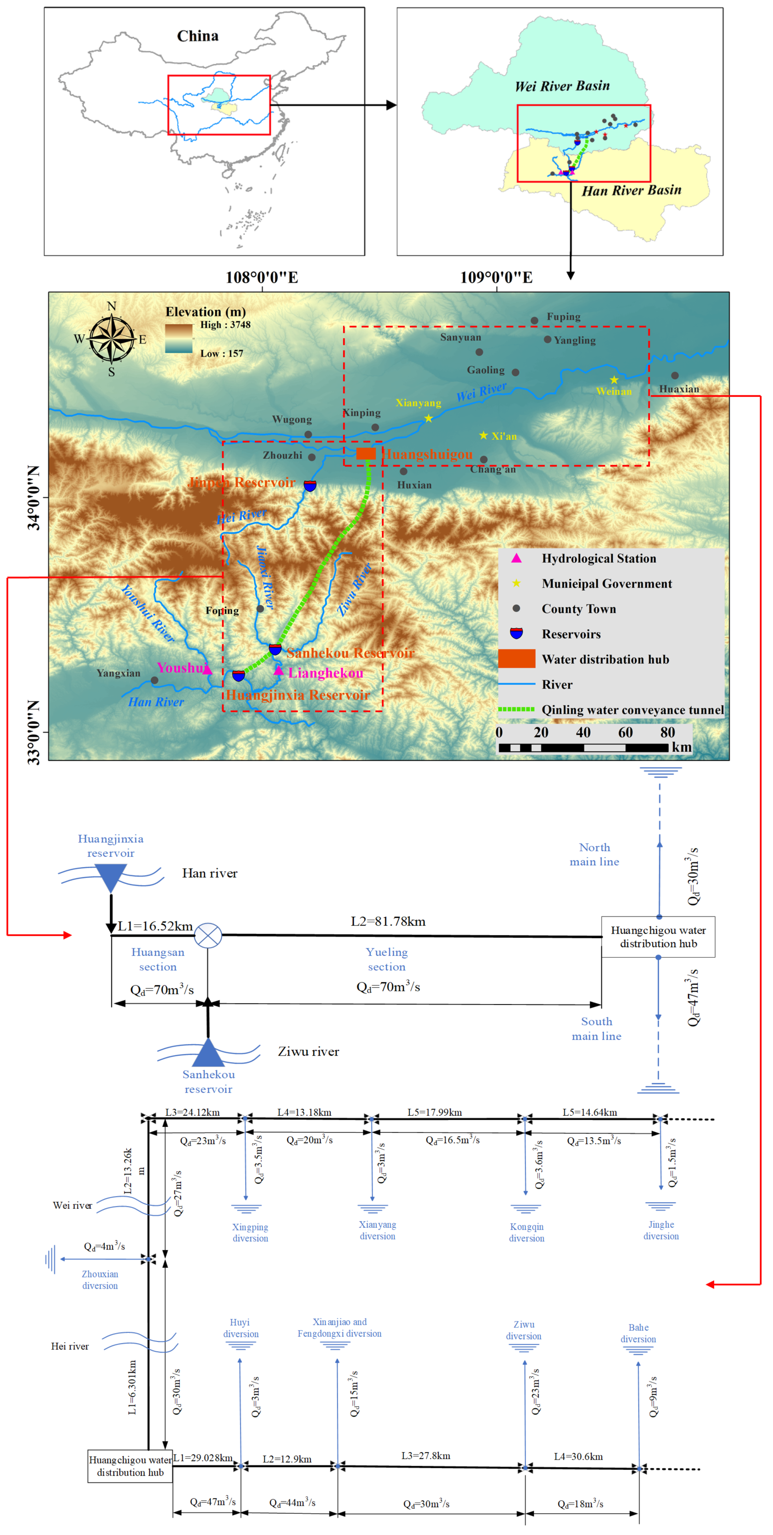
Figure 1. Location of the study basin and main water transmission and distribution project, including Qinling water conveyance tunnel and north–south main line Phases I and II.
Water 16 00572 g001
Figure 2. The distribution of flow rates and cross-sectional profiles along the HTWDP, including Qinling water conveyance tunnel and north–south main line Phases I and II.
Water 16 00572 g002
Figure 3. Concept map of Preissmann virtual narrow gap. (a) Non-pressure pipelines; (b) pressure pipelines.
Water 16 00572 g003
Figure 4. Schematic diagram of the flow relationship with diversion reach.
Water 16 00572 g004
Figure 5. Inflow processes of various nodes.
Water 16 00572 g005
Figure 6. Water demand process of diversion point. (a) South main line; (b) North main line.
Water 16 00572 g006
Figure 7. The flow chart of the entire flow routing simulation process for IBWT.
Water 16 00572 g007
Figure 8. Water flow routing time. (a) Qinling water conveyance tunnel; (b) South main line; (c) North main line.
Water 16 00572 g008aWater 16 00572 g008b
Figure 9. Comparison of simulated flow rates and calculated flow rates at various outlet sections without utilizing the Preissmann virtual narrow gap method. (a) South main line; (b) North main line.
Water 16 00572 g009aWater 16 00572 g009b
Figure 10. Comparison of simulated flow rates and calculated flow rates at various outlet sections under the Preissmann virtual narrow gap method. (a) Qinling water conveyance tunnel; (b) South main line; (c) North main line.
Water 16 00572 g010aWater 16 00572 g010b
Figure 11. Simulated flow processes and inverted flow processes at the entrance sections of various nodes; P-average and C-average represent the average of proposed values and calculated values, respectively. (a) Qinling water conveyance tunnel; (b) South main line; (c) North main line.
Water 16 00572 g011aWater 16 00572 g011b
Table 1. The calibration values of Muskingum parameters in each hub.
ParameterC0C1C2kx
Qinling tunnel0.02190.02870.949319.30270.0035
South main line−0.00860.01370.9949197.83520.0111
North main line0.0438−0.03240.988683.9458−0.0398
Table 2. The KGE index of each hub in different methods.
KGEQinling TunnelSouth Main LineNorth Main Line
Preissmann0.760.730.65
Non-Preissmann 0.380.27
Table 3. Comparison between the proposed values and inverted average values at the entrance sections of various nodes.
ProjectQinling Tunnel
(m3/s)
South Main Line
(m3/s)
North Main Line
(m3/s)
Proposed average55.1543.5127.30
Inverted average56.1344.1428.24
Disclaimer/Publisher’s Note: The statements, opinions and data contained in all publications are solely those of the individual author(s) and contributor(s) and not of MDPI and/or the editor(s). MDPI and/or the editor(s) disclaim responsibility for any injury to people or property resulting from any ideas, methods, instructions or products referred to in the content.