
Barrier Effect of Existing Building Pile on the Responses of Groundwater and Soil During Foundation Pit Dewatering


 ,
,
Abstract
1. Introduction
2. Engineering Background
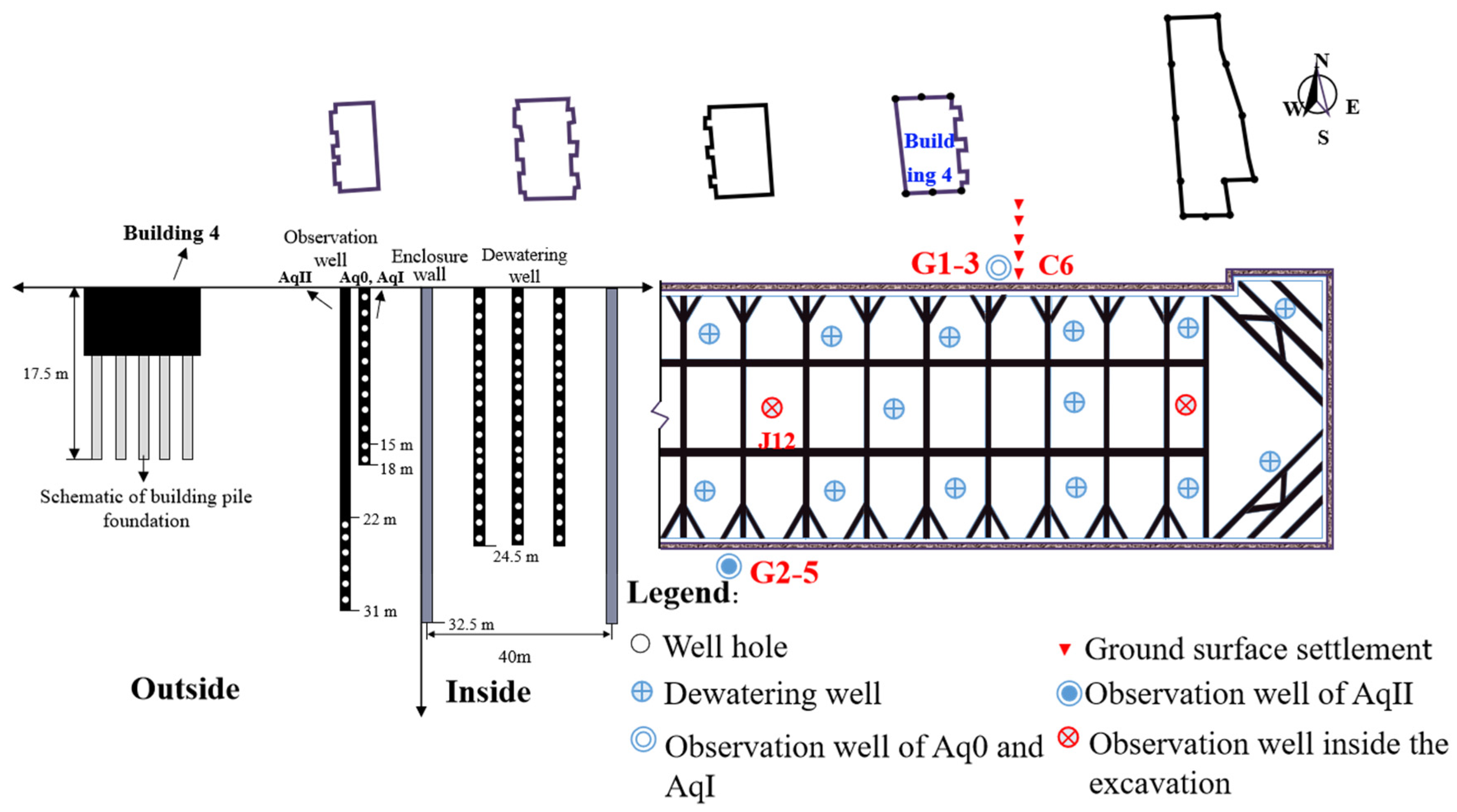
2.1. Project Description
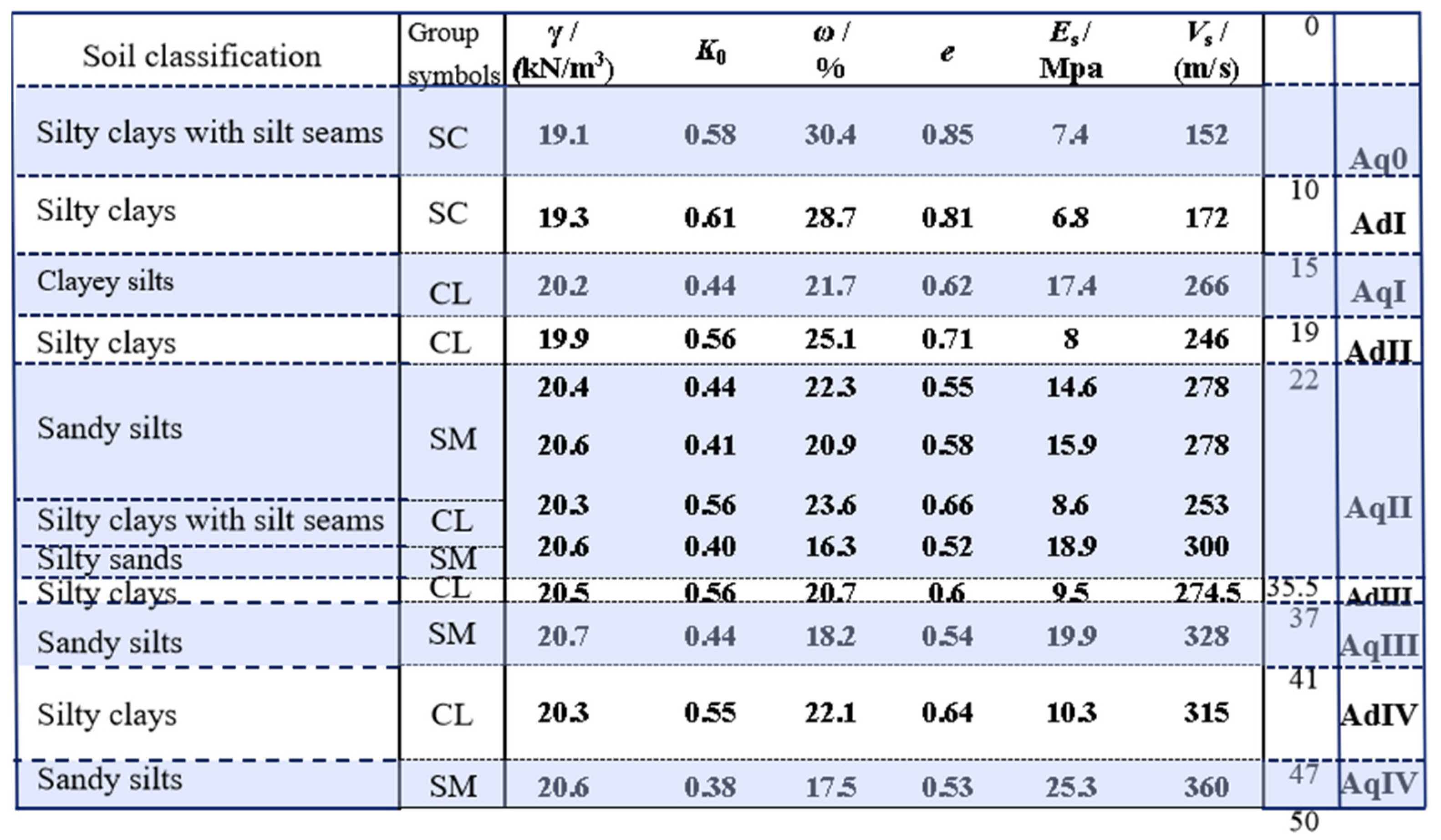
2.2. Geological Conditions
2.3. Pumping Test
3. Numerical Analysis
3.1. Modeling Scheme
3.2. Model Setup
3.3. Model Validation
4. Simulation Results and Analysis
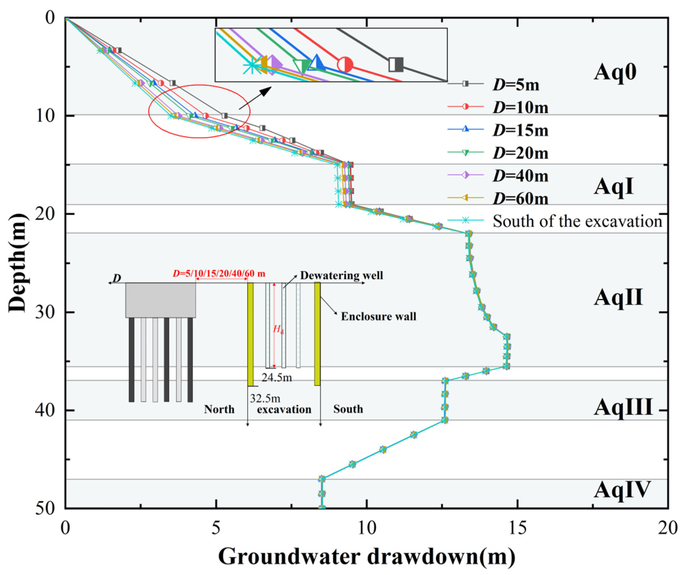
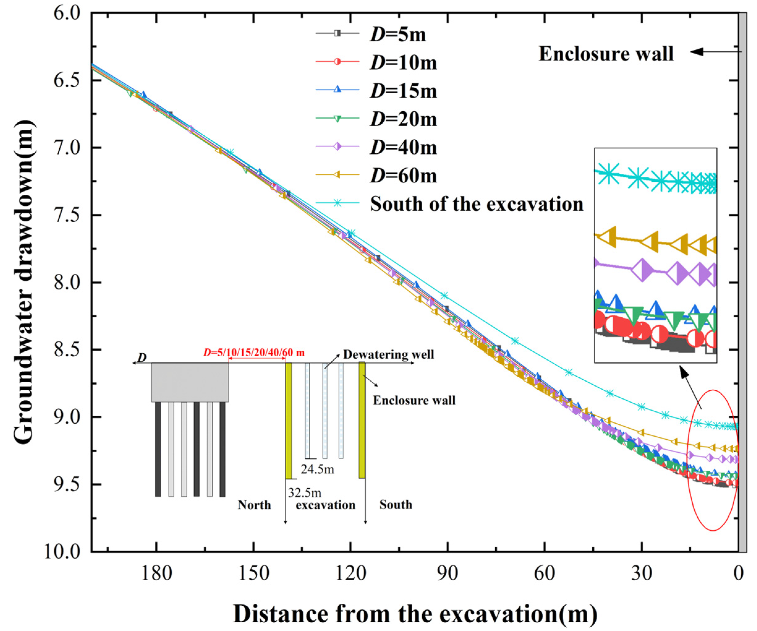
4.1. Distribution of Groundwater Drawdown
- Compared to the side without building pile foundations, the side with building pile foundations has a greater depth of groundwater drawdown. This is because groundwater flow toward the foundation pit is hindered by the presence of building piles, causing some groundwater to circumvent the underground structures, thereby elongating its seepage pathway;
- As D increases, the drawdown of water level outside the foundation pit decreases, approaching the drawdown observed without building piles. This indicates that the farther the pile foundations are from the foundation pit, the weaker their barrier effect on water;
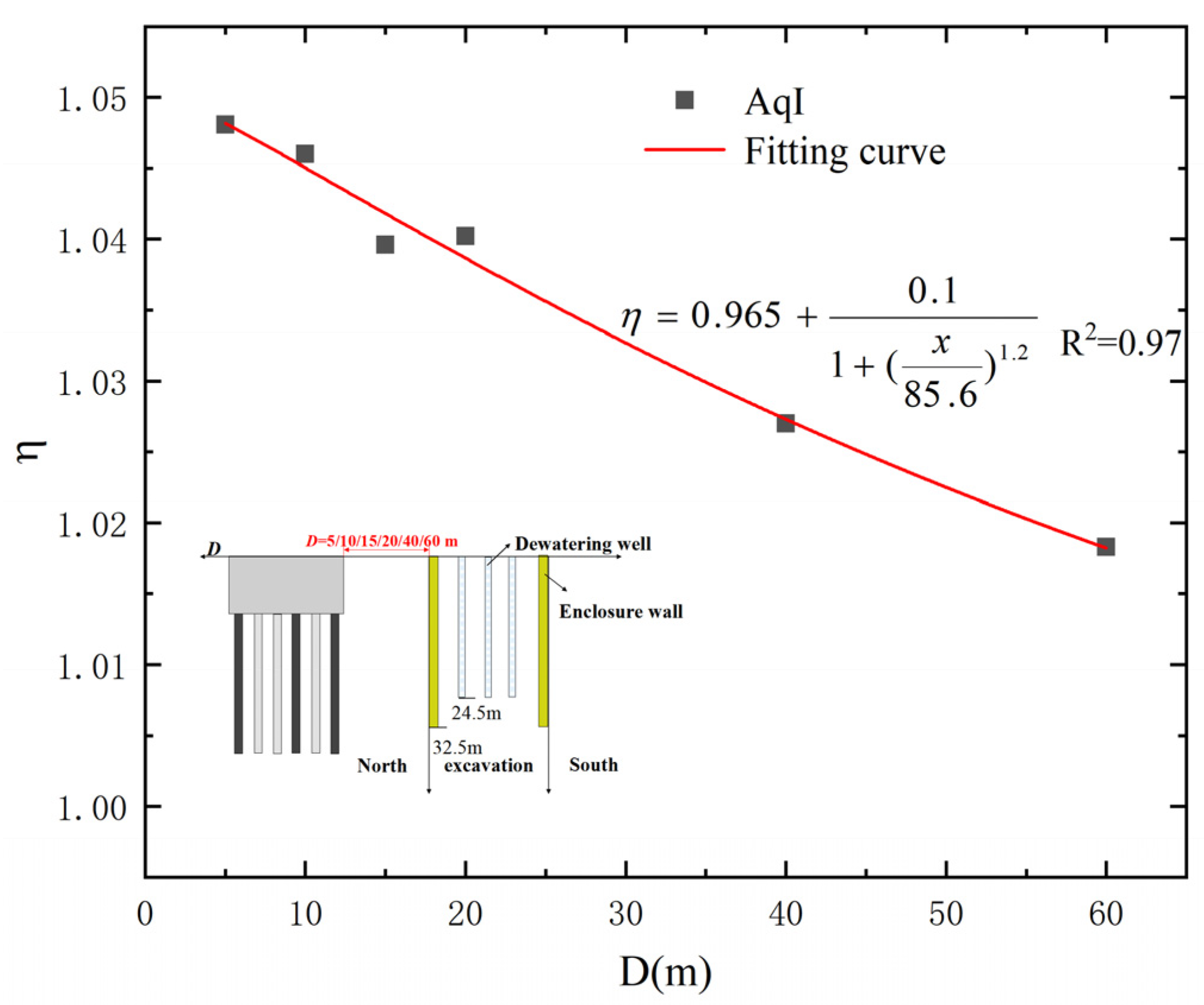
- In Aq0, the variation in water levels outside the foundation pit is significantly influenced by D on the sides with pile foundations. However, below Aq0, the differences in water level variations between sides with and without pile foundations gradually diminish. This is because within the depth range of the Aq0, there are underground structures such as building basements, which create a strong barrier effect on groundwater. Below this depth range are pile foundations, where the soil between the piles allows groundwater to seep through, thus significantly reducing their barrier effect on water.
4.2. Distribution of Enclosure Wall Deflection and Ground Surface Settlement
- Regardless of whether there are pile foundations outside the foundation pit or not, dewatering inside the foundation pit causes the enclosure wall to undergo an inward ‘bulging’ type of deflection. This is because the initial support provided by the first construction stage before dewatering causes minimal lateral movement at the head on the enclosure wall. At the same time, the deeper soil exerts a constraining effect on the bottom of the enclosure wall, resulting in less lateral movement at deeper positions of the enclosure wall. Therefore, the deformation of the enclosure wall mainly occurs in the near-middle section;
- When there are foundation piles outside the foundation pit, as D increases, the lateral movement of the enclosure wall caused by dewatering also increases but overall remains smaller than when there are not pile foundations (i.e., at the south side of the foundation pit).
- Dewatering causes a dual settlement groove pattern in the ground surface on the north side of the foundation pit (i.e., the settlement groove behind the existing pile foundations and the settlement groove between the enclosure wall and the existing pile foundations). While on the south side without pile foundations, the ground settlement outside the foundation pit exhibits a single settlement groove pattern;
- For the scenarios with ground surface settlement involving existing pile foundations, when D < 40 m (i.e., D = 5 m, 10 m, 15 m, and 20 m), the ground settlement between the enclosure wall and the existing pile foundations is less than without pile foundations (i.e., the ground settlement corresponding to the south side of the pit); when D ≥ 40 (i.e., D = 40 m and 60 m), the ground settlement between the enclosure wall and the existing pile foundations is greater than without pile foundations. This indicates that during the pre-excavation dewatering process, as D increases, both the soil-blocking effect and the water-blocking effect gradually diminish. Moreover, when D < 40 m, the barrier effect of the soil plays a predominant role, thereby hindering the settlement of the soil between the existing pile foundations and the enclosure wall. When D > 40 m, the water-blocking effect plays a predominant role, thereby lengthening the flow path, resulting in a more significant decrease in groundwater level between the existing pile foundations and the enclosure wall, consequently leading to greater settlement.
- When existing pile foundations hinder the movement of soil, they themselves deform with the movement of the soil, resulting in uneven settlement. This is particularly evident when they are close to the foundation pit, but the settlement of the pile foundations is always less than the settlement of the nearby ground surface;
- As D increases, the settlement of the building transitions from a greater settlement at the front side compared to the back side to gradually less settlement at the front side compared to the backside. It is important to consider this pattern and its impact on the structural integrity during the project.
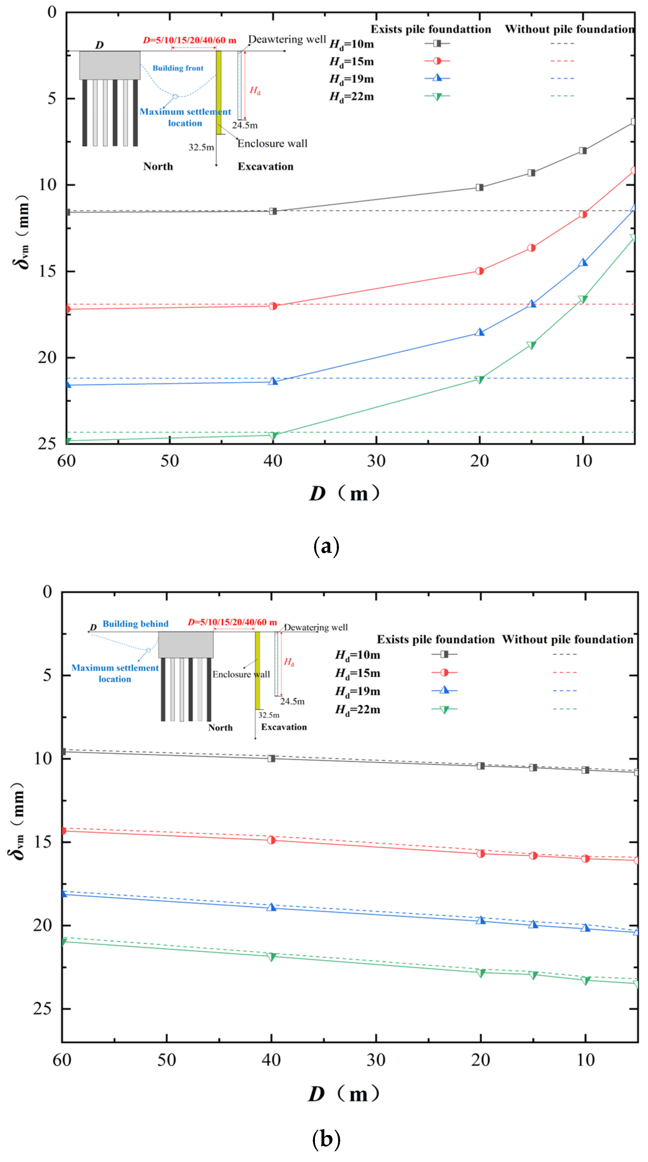
4.3. Distribution of Maximum Ground Settlement and Maximum Enclosure Wall Deflection
- Overall, the pumping causes both the front δvm and δhm of the existing pile foundations outside the pit to increase with the increase in D. This trend becomes more pronounced under deeper dewatering depths. This reflects the impact of the continuous weakening effect of existing pile foundations outside the foundation pit on restraining soil movement;
- As in Figure 8a, in the front of the existing pile foundations, when D ≤ 40 m, the δvm on the side with existing pile foundations is significantly smaller than the δvm under the same conditions when there are not pile foundations. This is because the barrier effect of the building has a positive influence. Furthermore, it primarily relies on the water-blocking effect. However, when (D > 40 m), the δvm on the side with existing pile foundations is slightly larger than the δvm under the same conditions without pile foundations. This is because the barrier effect of the building has a negative impact, primarily relying on the soil-blocking effect. It can be considered that under the same dewatering depth, there exists a critical value for D in terms of the influence of dewatering-induced δvm. As D changes, the coupled effects of barrier pile foundations on the soil and pile foundations on the water gradually become apparent;
- As in Figure 8b, At the same dewatering depth, the δvm behind the existing pile foundations gradually decreases with increasing D. The δvm on the side with/without existing pile foundations is roughly the same. This is because water can permeate between the pile foundations; Thus, the extent of water level decline behind the pile foundations is similar to that on the side without pile foundations (see Figure 5), resulting in similar consolidation settlement of the soil mass;
- From Figure 8c, it can be observed that with increasing dewatering depth, δhm shows a pattern of initially increasing and then decreasing, reaching its maximum at Hd = 15 m. This is because when the dewatering depth is shallow (Hd ≤ 15 m), there is less groundwater replenishment from outside the foundation pit to the inside, resulting in smaller maximum lateral displacement under corresponding conditions. However, when the dewatering depth is greater (Hd > 15 m), the water level inside the foundation pit decreases significantly, while groundwater from outside the foundation pit promptly replenishes into it. This results in a significant decrease in water levels both inside and outside the foundation pit, causing the enclosure wall to exhibit lateral displacement tendencies in both directions—towards the inside and outside of the foundation pit. Due to these two trends counteracting each other, the maximum lateral displacement under these conditions is smaller compared to when the dewatering depth Hd = 15 m. Because the barrier effect plays a positive role in restraining the lateral deformation of the enclosure wall, δhm is consistently less than the maximum lateral displacement of the enclosure wall without pile foundations.
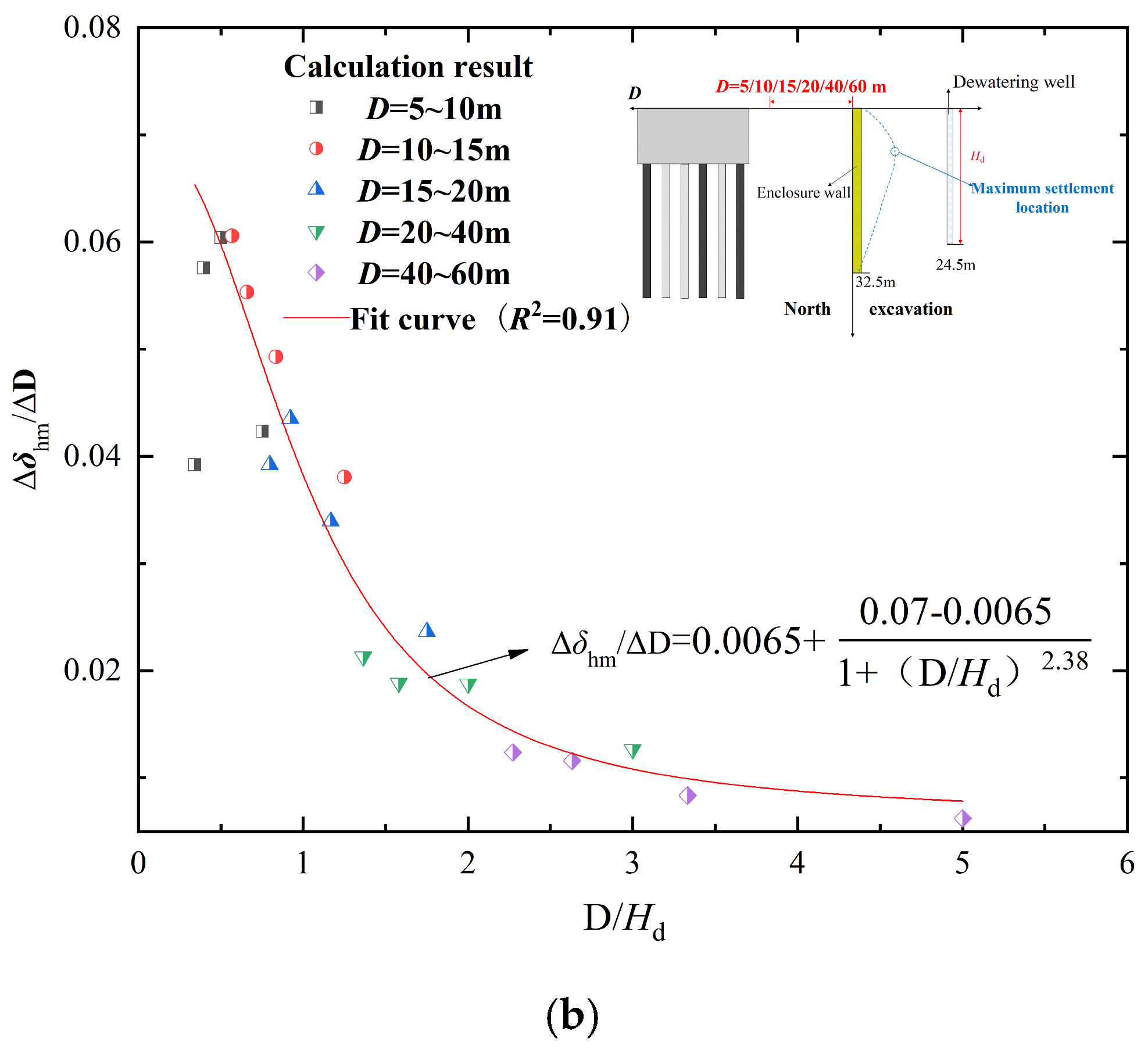
- δvm mostly lies between δvm = 1.88 δhm and δvm = 5.52 δhm, caused by pre-watering excavation, with δvm ranging from 0.051% Hd to 0.114% Hd, and δhm changes from 0.015 Hd to 0.044 Hd. The ratio relationship between δvm and δhm in this study is generally within the range of the measurement data from Zhang et al. [102] (i.e., from δvm = δhm to δvm = 10 δhm). Zhang et al. and this study both investigate the relationship between the changes in δvm and δhm caused by foundation pit dewatering when there is hydraulic connectivity between the inside and outside of the foundation pit (i.e., dewatering inside the pit leads to a rapid decline in the water level outside the pit);
- As D continues to increase, the slope of the relationship between δvm and δhm also increases correspondingly. This is because, as D increases, the barrier effect of the building gradually weakens, which aggravates surface ground settlement while also restraining the lateral displacement of the enclosure wall. In addition, as the depth of dewatering (Hd) increases, it will also lead to an increase in the slope of the relationship between δvm and δhm.
4.4. Maximum Settlement Increment and Maximum Lateral Displacement Increment
5. Discussion
6. Conclusions
- From the perspective of the depth distribution of water level drawdown outside the pit, the water level drawdown on the side with a building pile foundation is greater than that on the side without any buildings. It is noteworthy that in the aquifer layer Aq0, the changes in water level outside the foundation pit on both sides with and without building pile foundations are significantly influenced by distance (D), while below the aquifer layer Aq0, the differences in water level changes between both sides gradually diminish. From the perspective of the horizontal distribution of water level drawdown outside the foundation pit, the further away from the foundation pit, the smaller the water level drawdown. As the distance (D) increases, the barrier effect of the building pile foundation on the water gradually weakens;
- From the perspective of enclosure wall deformation patterns, due to the presence of the first support at the top of the diaphragm wall of the foundation pit, the maximum lateral displacement generated by the enclosure wall occurs primarily around a depth of 10 m, regardless of the presence or absence of building pile foundations. Under the same dewatering depth conditions, the lateral displacement of the enclosure wall increases gradually with the distance between existing building pile foundations and the foundation pit. Additionally, the lateral displacement of the enclosure wall on the north side of the foundation pit is consistently smaller than that on the south side at corresponding positions. This indicates that both the barrier effect of the existing building pile foundation soil and the barrier effect of the existing building pile foundation water positively influence the lateral displacement pattern of the enclosure wall;
- From the perspective of ground surface settlement patterns between the existing building pile foundation and the pit, when there are not building pile foundations, the settlement outside the pit caused by pre-excavation dewatering exhibits a single settlement groove. If there are building pile foundations, it manifests as a double settlement groove pattern. Under the same dewatering conditions, the distance (D) between the building pile foundation and the pit increases, and the settlement of the soil outside the pit also increases. When D < 40 m, the soil-blocking effect gradually diminishes with increasing D, resulting in the settlement of the soil being less than that at the corresponding position on the south side of the pit. However, when D > 40 m, the soil-barrier effect significantly weakens, while the pile foundations enhance their obstruction to groundwater flow, leading to settlement being greater than that at the corresponding position on the south side of the foundation pit. From the perspective of ground surface settlement patterns behind the building pile foundation outside the foundation pit, the settlement of the soil behind the building pile foundation is greater compared to the settlement at corresponding positions without building pile foundations. Moreover, the settlement of the soil behind the existing building pile foundations gradually approaches the settlement at corresponding positions on the south side of the foundation pit as D increases;
- Regarding the maximum settlement of the soil outside the foundation pit and the maximum lateral movement of the enclosure wall, as well as their increments, δvm mostly lies between δvm = 1.88 δhm and δvm = 5.52, with δhm caused by pre-watering excavation. It is largely consistent with the measurement data from Zhang et al., ranging from δvm = δhm to δvm = 10 δhm. There exists a critical value for the influence of different D values on δvm of the soil between the building pile foundation and the foundation pit (i.e., D = 40 m). The settlement of the soil behind the building pile foundation decreases linearly with increasing D. The greater the depth of dewatering, the more pronounced that the influence of the building pile foundation on deformation induced by pumping becomes.
Author Contributions
Funding
Data Availability Statement
Acknowledgments
Conflicts of Interest
References
- Zhang, D.; Shen, Y.; Huang, Z.; Xie, X. Auto machine learning-based modelling and prediction of excavation-induced tunnel displacement. J. Rock Mech. Geotech. Eng. 2022, 14, 1100–1114. [Google Scholar] [CrossRef]
- Zhang, W.; Zhang, R.; Wang, W.; Zhang, F.; Goh, A.T.C. A Multivariate Adaptive Regression Splines model for determining horizontal wall deflection envelope for braced excavations in clays. Tunn. Undergr. Space Technol. 2019, 84, 461–471. [Google Scholar] [CrossRef]
- Waichita, S.; Jongpradist, P.; Jamsawang, P. Characterization of deep cement mixing wall behavior using wall-to-excavation shape factor. Tunn. Undergr. Space Technol. 2019, 83, 243–253. [Google Scholar] [CrossRef]
- Soomro, M.A.; Mangnejo, D.A.; Bhanbhro, R.; Memon, N.A.; Memon, M.A. 3D finite element analysis of pile responses to adjacent excavation in soft clay: Effects of different excavation depths systems relative to a floating pile. Tunn. Undergr. Space Technol. 2019, 86, 138–155. [Google Scholar] [CrossRef]
- Jamsawang, P.; Voottipruex, P.; Tanseng, P.; Jongpradist, P.; Bergado, D.T. Effectiveness of deep cement mixing walls with top-down construction for deep excavations in soft clay: Case study and 3D simulation. Acta Geotech. 2019, 14, 225–246. [Google Scholar] [CrossRef]
- Goh, A.T.C.; Zhang, F.; Zhang, W.; Zhang, Y.; Liu, H. A simple estimation model for 3D braced excavation wall deflection. Comput. Geotech. 2017, 83, 106–113. [Google Scholar] [CrossRef]
- Zeng, C.-F.; Powrie, W.; Chen, H.-B.; Wang, S.; Diao, Y.; Xue, X.-L. Ground Behavior due to Dewatering Inside a Foundation Pit Considering the Barrier Effect of Preexisting Building Piles on Aquifer Flow. J. Geotech. Geoenviron. Eng. 2024, 150, 05024004. [Google Scholar] [CrossRef]
- Xue, X.-L.; Sun, H.-Y.; Zeng, C.-F.; Chen, H.-B.; Zheng, G.; Xu, C.-J.; Han, L. Why pile-supported building settled continuously after water level was stabilized during dewatering: Clues from interaction between pile and multi aquifers. J. Hydrol. 2024, 638, 131539. [Google Scholar] [CrossRef]
- Zeng, C.-F.; Chen, H.-B.; Liao, H.; Xue, X.-L.; Chen, Q.-N.; Diao, Y. Behaviours of groundwater and strata during dewatering of large-scale excavations with a nearby underground barrier. J. Hydrol. 2023, 620, 129400. [Google Scholar] [CrossRef]
- Xue, T.; Xue, X.; Long, S.; Chen, Q.; Lu, S.; Zeng, C. Effect of Pre-Existing Underground Structures on Groundwater Flow and Strata Movement Induced by Dewatering and Excavation. Water 2023, 15, 814. [Google Scholar] [CrossRef]
- Zeng, C.-F.; Liao, H.; Xue, X.-L.; Long, S.-C.; Luo, G.-J.; Diao, Y.; Li, M.G. Responses of groundwater and soil to dewatering considering the barrier effect of adjacent metro station on multi-aquifers. J. Hydrol. 2022, 612, 128117. [Google Scholar] [CrossRef]
- Liu, H.; Li, P.; Liu, J. Numerical investigation of underlying tunnel heave during a new tunnel construction. Tunn. Undergr. Space Technol. 2011, 26, 276–283. [Google Scholar] [CrossRef]
- Ng, C.W.W.; Shi, J.; Hong, Y. Three-dimensional centrifuge modelling of basement excavation effects on an existing tunnel in dry sand. Can. Geotech. J. 2013, 50, 874–888. [Google Scholar] [CrossRef]
- Zhang, Z.; Huang, M.; Wang, W. Evaluation of deformation response for adjacent tunnels due to soil unloading in excavation engineering. Tunn. Undergr. Space Technol. 2013, 38 (Suppl. C), 244–253. [Google Scholar] [CrossRef]
- Ng, C.W.W.; Sun, H.S.; Lei, G.H.; Shi, J.W.; Mašín, D. Ability of three different soil constitutive models to predict a tunnel’s response to basement excavation. Can. Geotech. J. 2015, 52, 1685–1698. [Google Scholar] [CrossRef]
- Shi, J.; Ng, C.W.W.; Chen, Y. Three-dimensional numerical parametric study of the influence of basement excavation on existing tunnel. Comput. Geotech. 2015, 63, 146–158. [Google Scholar] [CrossRef]
- Chen, R.; Meng, F.; Li, Z.; Ye, Y.; Ye, J. Investigation of response of metro tunnels due to adjacent large excavation and protective measures in soft soils. Tunn. Undergr. Space Technol. 2016, 58 (Suppl. C), 224–235. [Google Scholar] [CrossRef]
- Liu, G.B.; Huang, P.; Shi, J.W.; Ng, C.W.W. Performance of a Deep Excavation and Its Effect on Adjacent Tunnels in Shanghai Soft Clay. J. Perform. Constr. Facil. 2016, 30, 04016041. [Google Scholar] [CrossRef]
- Shi, J.; Ng, C.W.W.; Chen, Y. A simplified method to estimate three-dimensional tunnel responses to basement excavation. Tunn. Undergr. Space Technol. 2017, 62 (Suppl. C), 53–63. [Google Scholar] [CrossRef]
- Liang, R.; Wu, W.; Yu, F.; Jiang, G.; Liu, J. Simplified method for evaluating shield tunnel deformation due to adjacent excavation. Tunn. Undergr. Space Technol. 2018, 71 (Suppl. C), 94–105. [Google Scholar] [CrossRef]
- Whittle, A.J.; Corral, G.; Jen, L.C.; Rawnsley, R.P. Prediction and Performance of Deep Excavations for Courthouse Station, Boston. J. Geotech. Geoenviron. Eng. 2015, 141, 04014123. [Google Scholar] [CrossRef]
- Orazalin, Z.Y.; Whittle, A.J.; Olsen, M.B. Three-dimensional analyses of excavation support system for the Stata Center basement on the MIT campus. J. Geotech. Geoenviron. Eng. 2015, 141, 05015001. [Google Scholar] [CrossRef]
- Bryson, L.; Zapata-Medina, D. Method for estimating system stiffness for excavation support walls. J. Geotech. Geoenviron. Eng. 2012, 138, 1104–1115. [Google Scholar] [CrossRef]
- Finno, R.J.; Roboski, J.F. Three-dimensional responses of a tied-back excavation through clay. J. Geotech. Geoenviron. Eng. 2005, 131, 273–282. [Google Scholar] [CrossRef]
- Moormann, C. Analysis of wall and ground movements due to deep excavations in soft soil based on a new worldwide database. Soils Found. 2004, 44, 87–98. [Google Scholar] [CrossRef]
- Zeng, C.-F.; Xue, X.-L.; Li, M.-K. Use of cross wall to restrict enclosure movement during dewatering inside a metro pit before soil excavation. Tunn. Undergr. Space Technol. 2021, 112, 103909. [Google Scholar] [CrossRef]
- Zeng, C.-F.; Wang, S.; Xue, X.-L.; Zheng, G.; Mei, G.-X. Evolution of deep ground settlement subject to groundwater drawdown during dewatering in a multi-layered aquifer-aquitard system: Insights from numerical modelling. J. Hydrol. 2021, 603, 127078. [Google Scholar] [CrossRef]
- Zeng, C.-F.; Song, W.-W.; Xue, X.-L.; Li, M.-K.; Bai, N.; Mei, G.-X. Construction dewatering in a metro station incorporating buttress retaining wall to limit ground settlement: Insights from experimental modelling. Tunn. Undergr. Space Technol. 2021, 116, 104124. [Google Scholar] [CrossRef]
- Zeng, C.F.; Powrie, W.; Xue, X.L.; Li, M.K.; Mei, G.X. Effectiveness of a buttress wall in reducing retaining wall movement during dewatering before bulk excavation. Acta Geotech. 2021, 16, 3253–3267. [Google Scholar] [CrossRef]
- De Caro, M.; Crosta, G.B.; Previati, A. Modelling the interference of underground structures with groundwater flow and remedial solutions in Milan. Eng. Geol. 2020, 272, 105652. [Google Scholar] [CrossRef]
- Zhang, Y.Q.; Wang, J.H.; Li, M.G. Effect of Dewatering in a Confined Aquifer on Ground Settlement in Deep Excavations. Int. J. Geomech. 2018, 18, 04018120. [Google Scholar] [CrossRef]
- Zhang, Y.; Yu, J.; Gong, X.; Wu, J.; Wang, Z. Pumping-induced stress and strain in aquifer systems in Wuxi, China. Hydrogeol. J. 2018, 26, 771–787. [Google Scholar] [CrossRef]
- Gu, K.; Shi, B.; Liu, C.; Jiang, H.; Li, T.; Wu, J. Investigation of land subsidence with the combination of distributed fiber optic sensing techniques and microstructure analysis of soils. Eng. Geol. 2018, 240, 34–47. [Google Scholar] [CrossRef]
- Figueroa-Miranda, S.; Tuxpan-Vargas, J.; Ramos-Leal, J.A.; Hernández-Madrigal, V.M.; Villaseñor-Reyes, C.I. Land subsidence by groundwater over-exploitation from aquifers in tectonic valleys of Central Mexico: A review. Eng. Geol. 2018, 246, 91–106. [Google Scholar] [CrossRef]
- Zhang, Y.Q.; Li, M.G.; Wang, J.H.; Chen, J.J.; Zhu, Y.F. Field tests of pumping-recharge technology for deep confined aquifers and its application to a deep excavation. Eng. Geol. 2017, 228, 249–259. [Google Scholar] [CrossRef]
- Zhang, Y.; Wu, J.; Xue, Y.; Wang, Z. Fully coupled three-dimensional nonlinear numerical simulation of pumping-induced land movement. Environ. Earth Sci. 2017, 76, 552. [Google Scholar] [CrossRef]
- Pedro, A.M.G.; Zdravković, L.; Potts, D.; Almeida e Sousa, J. Derivation of model parameters for numerical analysis of the Ivens shaft excavation. Eng. Geol. 2017, 217, 49–60. [Google Scholar] [CrossRef]
- Motagh, M.; Shamshiri, R.; Haghighi, M.H.; Wetzel, H.U.; Akbari, B.; Nahavandchi, H.; Roessner, S.; Arabi, S. Quantifying groundwater exploitation induced subsidence in the Rafsanjan plain, southeastern Iran, using InSAR time-series and in situ measurements. Eng. Geol. 2017, 218, 134–151. [Google Scholar] [CrossRef]
- Wang, J.; Wu, Y.; Liu, X. Areal subsidence under pumping well–curtain interaction in subway foundation pit dewatering: Conceptual model and numerical simulations. Environ. Earth Sci. 2016, 75, 1–13. [Google Scholar] [CrossRef]
- Pujades, E.; Jurado, A.; Carrera, J.; Vázquez-Suñé, E.; Dassargues, A. Hydrogeological assessment of non-linear underground enclosures. Eng. Geol. 2016, 207, 91–102. [Google Scholar] [CrossRef]
- Zhu, L.; Gong, H.; Li, X.; Wang, R.; Chen, B.; Dai, Z.; Teatini, P. Land subsidence due to groundwater withdrawal in the northern Beijing plain, China. Eng. Geol. 2015, 193, 243–255. [Google Scholar] [CrossRef]
- Nejjar, K.; Dias, D.; Cuira, F.; Chapron, G.; Lebissonnais, H. Experimental study of the performance of a 32 m deep excavation in the suburbs of Paris. Géotechnique 2021, 73, 469–479. [Google Scholar] [CrossRef]
- Sailer, E.; Taborda, D.M.G.; Zdravković, L.; Potts, D.M. Fundamentals of the coupled thermo-hydro-mechanical behaviour of thermo-active retaining walls. Comput. Geotech. 2019, 109, 189–203. [Google Scholar] [CrossRef]
- Finno, R.J.; Kim, S.; Lewis, J.; Winkle, N.V. Observed Performance of a Sheetpile-Supported Excavation in Chicago Clays. J. Geotech. Geoenviron. Eng. 2019, 145, 05018005. [Google Scholar] [CrossRef]
- Faustin, N.E.; Elshafie, M.Z.E.B.; Mair, R.J. Case studies of circular shaft construction in London. Proc. Inst. Civ. Eng.-Geotech. Eng. 2018, 171, 391–404. [Google Scholar] [CrossRef]
- Schwamb, T.; Elshafie, M.Z.E.B.; Soga, K.; Mair, R.J. Considerations for monitoring of deep circular excavations. Proc. Inst. Civ. Eng.-Geotech. Eng. 2016, 169, 477–493. [Google Scholar] [CrossRef]
- Dong, Y.P.; Burd, H.J.; Houlsby, G.T. Finite-element analysis of a deep excavation case history. Géotechnique 2016, 66, 1–15. [Google Scholar] [CrossRef]
- Zeng, C.-F.; Zheng, G.; Zhou, X.-F.; Xue, X.-L.; Zhou, H.-Z. Behaviours of wall and soil during pre-excavation dewatering under different foundation pit widths. Comput. Geotech. 2019, 115, 103169. [Google Scholar] [CrossRef]
- Zeng, C.-F.; Zheng, G.; Xue, X.-L. Responses of deep soil layers to combined recharge in a leaky aquifer. Eng. Geol. 2019, 260, 105263. [Google Scholar] [CrossRef]
- Zeng, C.F.; Zheng, G.; Xue, X.L.; Mei, G.X. Combined recharge: A method to prevent ground settlement induced by redevelopment of recharge wells. J. Hydrol. 2019, 568, 1–11. [Google Scholar] [CrossRef]
- Zeng, C.F.; Xue, X.L.; Zheng, G.; Xue, T.Y.; Mei, G.X. Responses of retaining wall and surrounding ground to pre-excavation dewatering in an alternated multi-aquifer-aquitard system. J. Hydrol. 2018, 559, 609–626. [Google Scholar] [CrossRef]
- Zeng, C.-F.; Wang, S.; Xue, X.-L.; Zheng, G.; Mei, G.-X. Characteristics of ground settlement due to combined actions of groundwater drawdown and enclosure wall movement. Acta Geotech. 2022, 17, 4095–4112. [Google Scholar] [CrossRef]
- Chang, C.-T.; Sun, C.-W.; Duann, S.W.; Hwang, R.N. Response of a Taipei Rapid Transit System (TRTS) tunnel to adjacent excavation. Tunn. Undergr. Space Technol. 2001, 16, 151–158. [Google Scholar] [CrossRef]
- Doležalová, M. Tunnel complex unloaded by a deep excavation. Comput. Geotech. 2001, 28, 469–493. [Google Scholar] [CrossRef]
- Sharma, J.S.; Hefny, A.M.; Zhao, J.; Chan, C.W. Effect of large excavation on deformation of adjacent MRT tunnels. Tunn. Undergr. Space Technol. 2001, 16, 93–98. [Google Scholar] [CrossRef]
- Hu, Z.F.; Yue, Z.Q.; Zhou, J.; Tham, L.G. Design and construction of a deep excavation in soft soils adjacent to the Shanghai Metro tunnels. Can. Geotech. J. 2003, 40, 933–948. [Google Scholar] [CrossRef]
- Ou, C.-Y.; Liao, J.-T.; Cheng, W.-L. Building response and ground movements induced by a deep excavation. Géotechnique 2000, 50, 209–220. [Google Scholar] [CrossRef]
- Ong, D.E.L.; Leung, C.F.; Chow, Y.K. Time-Dependent Pile Behaviour Due to Excavation-Induced Soil Movement in Clay. In Proceedings of the 12th Pan-American Conference on Soil Mechanics and Geotechnical Engineering, Cambridge, MA, USA, 22–26 June 2003; pp. 2035–2040. [Google Scholar]
- Finno, R.J.; Voss, F.T.; Rossow, E.; Blackburn, J.T. Evaluating Damage Potential in Buildings Affected by Excavations. J. Geotech. Geoenviron. Eng. 2005, 131, 1199–1210. [Google Scholar] [CrossRef]
- Leung, C.F.; Ong, D.E.L.; Chow, Y.K. Pile behavior due to excavation-induced soil movement in clay. II: Collapsed wall. J. Geotech. Geoenviron. Eng. 2006, 132, 45–53. [Google Scholar] [CrossRef]
- Ong, D.E.L.; Leung, C.E.; Chow, Y.K. Pile behavior due to excavation-induced soil movement in clay. I: Stable wall. J. Geotech. Geoenviron. Eng. 2006, 132, 36–44. [Google Scholar] [CrossRef]
- Ong, D.E.L.; Leung, C.F.; Chow, Y.K. Behavior of pile groups subject to excavation-induced soil movement in very soft clay. J. Geotech. Geoenviron. Eng. 2009, 135, 1462–1474. [Google Scholar] [CrossRef]
- Chai, J.; Shen, S.; Ding, W.; Zhu, H.; Carter, J. Numerical investigation of the failure of a building in Shanghai, China. Comput. Geotech. 2014, 55, 482–493. [Google Scholar] [CrossRef]
- Shi, J.; Liu, G.; Huang, P.; Ng, C.W.W. Interaction between a large-scale triangular excavation and adjacent structures in Shanghai soft clay. Tunn. Undergr. Space Technol. 2015, 50, 282–295. [Google Scholar] [CrossRef]
- Tan, Y.; Huang, R.; Kang, Z.; Bin, W. Covered Semi-Top-Down Excavation of Subway Station Surrounded by Closely Spaced Buildings in Downtown Shanghai: Building Response. J. Perform. Constr. Facil. 2016, 30, 04016040. [Google Scholar] [CrossRef]
- Lim, A.; Ou, C.-Y. Performance and Three-Dimensional Analyses of a Wide Excavation in Soft Soil with Strut-Free Retaining System. Int. J. Geomech. 2018, 18, 05018007. [Google Scholar] [CrossRef]
- Lim, A.; Ou, C.-Y.; Hsieh, P.-G. An innovative earth retaining supported system for deep excavation. Comput. Geotech. 2019, 114, 103135. [Google Scholar] [CrossRef]
- Lim, A.; Ou, C.-Y.; Hsieh, P.-G. A novel strut-free retaining wall system for deep excavation in soft clay: Numerical study. Acta Geotech. 2019, 15, 1557–1576. [Google Scholar] [CrossRef]
- Li, M.-G.; Demeijer, O.; Chen, J.-J. Effectiveness of servo struts in controlling excavation-induced wall deflection and ground settlement. Acta Geotech. 2020, 15, 2575–2590. [Google Scholar] [CrossRef]
- Li, M.-G.; Chen, J.-J.; Xu, Y.-S.; Tong, D.-G.; Cao, W.-W.; Shi, Y.-J. Effects of groundwater exploitation and recharge on land subsidence and infrastructure settlement patterns in Shanghai. Eng. Geol. 2021, 282, 105995. [Google Scholar] [CrossRef]
- Zhou, H.Z.; Zheng, G.; He, X.P.; Wang, E.Y.; Guo, Z.Y.; Nie, D.Q.; Ma, S.K. Numerical modelling of retaining structure displacements in multi-bench retained excavations. Acta Geotech. 2020, 15, 2691–2703. [Google Scholar] [CrossRef]
- Feng, S.-J.; Lu, S.-F. Failure of a Retaining Structure in a Metro Station Excavation in Nanchang City, China. J. Perform. Constr. Facil. 2016, 30, 04015097. [Google Scholar] [CrossRef]
- Tan, Y.; Li, M. Measured performance of a 26 m deep top-down excavation in downtown Shanghai. Can. Geotech. J. 2011, 48, 704–719. [Google Scholar] [CrossRef]
- Tan, Y.; Wei, B. Observed Behaviors of a Long and Deep Excavation Constructed by Cut-and-Cover Technique in Shanghai Soft Clay. J. Geotech. Geoenviron. Eng. 2012, 138, 69–88. [Google Scholar] [CrossRef]
- Tan, Y.; Wei, B. Performance of an Overexcavated Metro Station and Facilities Nearby. J. Perform. Constr. Facil. 2012, 26, 241–254. [Google Scholar] [CrossRef]
- Tan, Y.; Wang, D. Characteristics of a large-scale deep foundation pit excavated by the central-island technique in Shanghai soft clay. I: Bottom-up construction of the central cylindrical shaft. J. Geotech. Geoenviron. Eng. 2013, 139, 1875–1893. [Google Scholar] [CrossRef]
- Hashash, Y.M.A.; Osouli, A.; Marulanda, C. Central Artery/Tunnel Project Excavation Induced Ground Deformations. J. Geotech. Geoenviron. Eng. 2008, 134, 1399–1406. [Google Scholar] [CrossRef]
- Lee, F.H.; Juneja, A.; Tan, T.S. Stress and pore pressure changes due to sand compaction pile installation in soft clay. Géotechnique 2004, 54, 1–16. [Google Scholar] [CrossRef]
- Hashash, Y.M.A.; Whittle, A.J. Mechanisms of Load Transfer and Arching for Braced Excavations in Clay. J. Geotech. Geoenviron. Eng. 2002, 128, 187–197. [Google Scholar] [CrossRef]
- Bolton, M.D.; Stewart, D.I. The effect on propped diaphragm walls of rising groundwater in stiff clay. Géotechnique 1994, 44, 111–127. [Google Scholar] [CrossRef]
- Mair, R.J. Developments in geotechnical engineering research: Application to tunnels and deep excavations. Unwin Memorial Lecture 1992. Proc. Inst. Civ. Eng. 1993, 93, 27–41. [Google Scholar]
- Gunn, M.J.; Clayton, C.R.I. Installation effects and their importance in the design of earth-retaining structures. Géotechnique 1992, 42, 137–141. [Google Scholar] [CrossRef]
- Fourie, A.B.; Potts, D.M. Comparison of finite element and limiting equilibrium analyses for an embedded cantilever retaining wall. Géotechnique 1989, 39, 175–188. [Google Scholar] [CrossRef]
- Potts, D.M.; Fourie, A.B. A numerical study of the effects of wall deformation on earth pressures. Int. J. Numer. Anal. Methods Geomech. 1986, 10, 383–405. [Google Scholar] [CrossRef]
- Wood, L.A.; Perrin, A.J. Observations of a strutted diaphragm wall in London clay: A preliminary assessment. Géotechnique 1984, 34, 563–579. [Google Scholar] [CrossRef]
- Hubbard, H.W.; Potts, D.M.; Miller, D.; Burland, J.B. Design of the retaining walls for the M25 cut and cover tunnel at Bell Common. Géotechnique 1984, 34, 495–512. [Google Scholar] [CrossRef]
- Burland, J.B.; Longworth, T.I.; Moore, J.F.A. A study of ground movement and progressive failure caused by a deep excavation in Oxford Clay. Géotechnique 1977, 27, 557–591. [Google Scholar] [CrossRef]
- Zhang, X.; Yang, J.; Zhang, Y.; Gao, Y. Cause investigation of damages in existing building adjacent to foundation pit in construction. Eng. Fail. Anal. 2018, 83, 117–124. [Google Scholar] [CrossRef]
- Zhu, C.; Yan, Z.; Lin, Y.; Xiong, F.; Tao, Z. Design and application of a monitoring system for a deep railway foundation pit project. IEEE Access 2019, 7, 107591–107601. [Google Scholar] [CrossRef]
- Zhang, Z.; Huang, M.; Zhang, C.; Jiang, K.; Lu, M. Time-domain analyses for pile deformation induced by adjacent excavation considering influences of viscoelastic mechanism. Tunn. Undergr. Space Technol. 2019, 85, 392–405. [Google Scholar] [CrossRef]
- Wei, H. Influence of foundation pit excavation and precipitation on settlement of surrounding buildings. Adv. Civ. Eng. 2021, 2021, 6638868. [Google Scholar] [CrossRef]
- Zhang, C.-H.; Wang, B.-T.; Liu, Y. Research on the Effective Control of Ground Settlement during Double-Layered Foundation Pit Dewatering Based on Seepage Control-Recharge Coupling Model. Adv. Civ. Eng. 2022, 2022, 9669176. [Google Scholar] [CrossRef]
- Shen, S.L.; Wu, Y.X.; Misra, A. Calculation of head difference at two sides of a cut-off barrier during excavation dewatering. Comput. Geotech. 2017, 91, 192–202. [Google Scholar] [CrossRef]
- Zhang, Q.; Hu, J.; Wang, J.; He, P.; Hou, L.L.; Lin, P.; Song, S. Study on the mechanical behavior of a foundation pit retaining structure adjacent to the pile foundation of a subway station. Environ. Earth Sci. 2021, 80, 704. [Google Scholar] [CrossRef]
- Liao, S.-M.; Wei, S.-F.; Shen, S.-L. Structural responses of existing metro stations to adjacent deep excavations in Suzhou, China. J. Perform. Constr. Facil. 2016, 30, 04015089. [Google Scholar] [CrossRef]
- Zheng, G.; Ha, D.; Loaiciga, H.; Zhou, H.; Zeng, C.; Zhang, H. Estimation of the hydraulic parameters of leaky aquifers based on pumping tests and coupled simulation/optimization: Verification using a layered aquifer in Tianjin, China. Hydrogeol. J. 2019, 27, 3081–3095. [Google Scholar] [CrossRef]
- Wu, Y.X.; Lyu, H.M.; Han, J.; Shen, S.L. Dewatering-Induced Building Settlement around a Deep Excavation in Soft Deposit in Tianjin, China. J. Geotech. Geoenviron. Eng. 2019, 145, 05019003. [Google Scholar] [CrossRef]
- Zhang, Y.-Q.; Wang, J.-H.; Chen, J.-J.; Li, M.-G. Numerical study on the responses of groundwater and strata to pumping and recharge in a deep confined aquifer. J. Hydrol. 2017, 548, 342–352. [Google Scholar] [CrossRef]
- Li, M.G.; Chen, J.J.; Xia, X.H.; Zhang, Y.Q.; Wang, D.F. Statistical and hydro-mechanical coupling analyses on groundwater drawdown and soil deformation caused by dewatering in a multi-aquifer-aquitard system. J. Hydrol. 2020, 589, 125365. [Google Scholar] [CrossRef]
- Wang, X.-W.; Yang, T.-L.; Xu, Y.-S.; Shen, S.-L. Evaluation of optimized depth of waterproof curtain to mitigate negative impacts during dewatering. J. Hydrol. 2019, 577, 123969. [Google Scholar] [CrossRef]
- Bear, J. Hydraulics of Groundwater: Courier Corporation; Dover Publications: New York, NY, USA, 2012. [Google Scholar]
- Zhang, W.; Goh, A.; Goh, K.; Chew, O.; Zhou, D.; Zhang, R. Performance of braced excavation in residual soil with groundwater drawdown. Undergr. Space 2018, 3, 150–165. [Google Scholar] [CrossRef]


| Hydrogeology | Soil Classification | Buried Depth/m | KH (m/d) | KV (m/d) | E (Map) | C′ (Kpa) | φ′ |
|---|---|---|---|---|---|---|---|
| Aq0 | Silty clays with silt seams | 0~10 | 0.03 | 0.003 | 43.5 | 17 | 25 |
| AdI | Silty clays | 10~15 | 0.025 | 0.001 | 56.3 | 18 | 23 |
| AqI | Clayey silts | 15~19 | 0.2 | 0.1 | 137.6 | 10 | 34 |
| AdII | Silty clays | 19~22 | 0.006 | 0.001 | 118.6 | 19 | 26 |
| Sandy silts | 22~24.5 | 2.5 | 0.5 | 151.8 | 8 | 34 | |
| Sandy silts | 24.5~29.5 | 1 | 0.2 | 153.3 | 8 | 36 | |
| AqII | Silty clays with silt seams | 29.5~32.5 | 1 | 0.16 | 128 | 17 | 26 |
| Silty sands | 32.5~35.5 | 3 | 0.6 | 178.5 | 7 | 37 | |
| AdIII | Silty clays | 35.5~37 | 0.02 | 0.004 | 152.1 | 19 | 26 |
| AqIII | Sandy silts | 37~41 | 3 | 0.9 | 214.5 | 10 | 34 |
| AdIV | Silty clays | 41~47 | 0.005 | 0.001 | 198.4 | 18 | 27 |
| AqIV | Silty sands | 47~50 | 3.5 | 1.5 | 257 | 7 | 38 |
Disclaimer/Publisher’s Note: The statements, opinions and data contained in all publications are solely those of the individual author(s) and contributor(s) and not of MDPI and/or the editor(s). MDPI and/or the editor(s) disclaim responsibility for any injury to people or property resulting from any ideas, methods, instructions or products referred to in the content. |
© 2024 by the authors. Licensee MDPI, Basel, Switzerland. This article is an open access article distributed under the terms and conditions of the Creative Commons Attribution (CC BY) license (https://creativecommons.org/licenses/by/4.0/).
Share and Cite
He, D.; Zeng, C.; Xu, C.; Xue, X.; Zhao, Y.; Han, L.; Sun, H. Barrier Effect of Existing Building Pile on the Responses of Groundwater and Soil During Foundation Pit Dewatering. Water 2024, 16, 2977. https://doi.org/10.3390/w16202977
He D, Zeng C, Xu C, Xue X, Zhao Y, Han L, Sun H. Barrier Effect of Existing Building Pile on the Responses of Groundwater and Soil During Foundation Pit Dewatering. Water. 2024; 16(20):2977. https://doi.org/10.3390/w16202977
Chicago/Turabian StyleHe, Dongyang, Chaofeng Zeng, Changjie Xu, Xiuli Xue, Youwu Zhao, Lei Han, and Haiyu Sun. 2024. "Barrier Effect of Existing Building Pile on the Responses of Groundwater and Soil During Foundation Pit Dewatering" Water 16, no. 20: 2977. https://doi.org/10.3390/w16202977
APA StyleHe, D., Zeng, C., Xu, C., Xue, X., Zhao, Y., Han, L., & Sun, H. (2024). Barrier Effect of Existing Building Pile on the Responses of Groundwater and Soil During Foundation Pit Dewatering. Water, 16(20), 2977. https://doi.org/10.3390/w16202977