Article

Features and Constitutive Model of Hydrate-Bearing Sandy Sediment’s Triaxial Creep Failure

1
State Key Laboratory of Offshore Natural Gas Hydrates, Beijing 102209, China
2
Sanya Offshore Oil & Gas Research Institute, Northeast Petroleum University, Sanya 572025, China
3
CNOOC Research Institute Co., Ltd., Beijing 100028, China
*
Author to whom correspondence should be addressed.
Water 2024, 16(20), 2947; https://doi.org/10.3390/w16202947
Submission received: 11 September 2024 / Revised: 12 October 2024 / Accepted: 15 October 2024 / Published: 16 October 2024
(This article belongs to the Special Issue Advanced Research on Marine Geology and Sedimentology)

Abstract

:
In the longstanding development of hydrate-bearing sediment (HBS) reservoirs, slow and permanent deformation of the formation will occur under the influence of stress, which endangers the safety of hydrate development projects. This paper takes hydrate-bearing sandy sediment (HBSS) as the research object and conducts triaxial compression creep tests at different saturation degrees (20%, 30%, and 40%). The results show that the hydrate-containing sandy sediments have strong creep characteristics, and accelerated creep phenomenon will occur under the long-term action of high stress. The longstanding destructive power of the specimen progressively raises with the increase in hydrate saturation, but the difference in the triaxial strength of the specimen progressively increases. This indicates that the damage to the hydrate structure during long-term loading is the main factor causing the strength decrease. Further, a new nonlinear creep constitutive model was developed by using the nonlinear Burgers model in series with the fractional-order viscoplastic body model, which can well describe the creep properties of HBSS at different saturation levels.

1. Introduction

Natural gas hydrates (NGH) are cage-like compounds formed by methane gas and water at low temperatures and high pressures, which are widely endowed in shallow layers of the deep ocean and permafrost in the onshore area [1,2]. NGH reserves are abundant and have high energy densities, and they are considered one of the most promising clean energy sources to be developed [3,4]. Currently, several countries, including the United States, Japan, China, Canada, and Russia, have carried out NGH test mining, proving the feasibility of NGH exploitation. Nevertheless, enormous challenges, for instance, insufficient stockpile strength, underdeveloped exploration and development technologies, and viable induced geological dangers pose significant challenges to the safe and effective development of NGHs [5,6].
A large number of engineering practices have shown that reservoir creep is closely associated with the longstanding stability and safe operation of mining activities [7]. It is crucial to thoroughly consider the creep behaviour of the rock mass in order to predict and mitigate the risks associated with geological engineering projects [8,9,10,11]. Through in situ observation in the field, it is found that the marine NGH reservoir has strong creep characteristics. For this reason, some academics are investigating the creep characteristics of NGH reservoirs [12,13,14]. Parameswaran et al. carried out creep experiments on THF-containing hydrate sediments, as well as obtained the deformation curves and deformation rates under different axial stresses. Li et al. [15]. carried out separately loaded creep experiments on frozen samples of hydrate-bearing sediment (HBS) and found that the creep behaviour of HBS has a strong temperature sensitivity. The resulting creep deformation and deformation rate increased significantly with increasing temperature. Miyazaki et al. [16]. established an empirical equation for the relationship between creep rate and triaxial loading rate by comparing triaxial experiments with creep experiments at different loading rates. Hu et al. [17] carried out a joint acoustic and creep experiment on a HBS, and established a correlation between acoustic characteristics and the mechanical behaviour of creep. The above studies have laid a solid foundation for the interpretation of the creep behaviour of HBS.
Establishing a creep constitutive model based on the results of creep tests conducted on hydrate-bearing sediments (HBSs) is a crucial aspect of understanding their behaviour under prolonged stress. This model aims to accurately reflect the actual creep conditions these sediments experience in real-world applications. Additionally, determining the relevant parameters for this model is vital, as these parameters influence the predictive accuracy of the model [18,19].
The creep constitutive model serves as a vital tool for accurately characterizing the creep behaviour of hydrate-bearing sediments (HBSs). By providing a comprehensive framework that captures the essential features of creep under varying stress conditions, this model effectively links experimental creep test data with numerical simulations of reservoir deformation [20,21]. This connection is crucial, as it enables researchers and engineers to translate laboratory findings into predictive models that can simulate the behaviour of HBSs in real-world scenarios. This research holds significant engineering application value [22]. The most commonly used basic models for the creep constitutive model of geotechnical materials are the Nishihara mode and the Burgers mode. When this load does not exceed the long-term strength, the classical constitutive model can describe the decelerated and stable creep of geotechnical materials. However, the model faces difficulties in describing the conduct of accelerated creep, for which scholars have proposed various modification strategies [23]. Specifically, these strategies include: (1) introducing damage elements: in different studies, scholars have adopted diverse damage equations to compensate for the model’s shortcomings in describing accelerated creep [24]; (2) handling viscoplastic units: fractional processing of the viscous components in viscoplastic units to enhance the model’s descriptive capabilities [25]; and (3) introducing winding elements: based on the principle of energy conservation, introducing winding elements to modify classical models more effectively describes the phenomenon of accelerated creep. In addition, Cheng et al. [26]. and Liu et al. [27]. have proposed improved models. Cheng et al. added damping units and nonlinear viscoplastic units to the classical Nishihara model to simulate the accelerated creep stage of soft rocks. Liu et al., on the other hand, developed a new improved model by connecting the Bingham model with the Nishihara damage model. These improvement methods can effectively describe the phenomenon of accelerated creep, providing strong support for research in related fields. In the above studies, there needs to be more data on the creep behaviour of hydrate, and the current research is mainly focused on the influence of hydrate saturation, temperature, and particle size on the creep behaviours of hydrate [28]. The creep constitutive model studies have focused on conventional geotechnical materials, while fewer studies have been conducted on hydrate-bearing sandy sediment (HBSS) [29,30]. The applicability of the developed model to HBSS needs to be further investigated.
Therefore, in order to expose this mechanical reaction and the deformation mechanism of HBSS under long-term loading conditions, triaxial compression creep tests were conducted in this study on HBSS with different saturation levels to analyse the deformation characteristics of HBSS under long-term loading [31,32]. Further, a new nonlinear creep constitutive model is set up by linking the Burgers model in series with the fractional-order viscoplastic body model [33,34,35]. The model is further validated by fitting it with the creep test results obtained from hydrate-bearing sandy sediments (HBSSs), showcasing its applicability and reliability in real-world conditions. The alignment between the model predictions and experimental data not only confirms the model’s effectiveness but also enhances its credibility for practical use. The findings from this study hold significant reference value for safety evaluations related to development projects involving HBSSs. By providing a robust framework for understanding the creep behaviour of these sediments, the model aids in assessing potential risks associated with reservoir deformation and stability.

2. Materials and Methods

2.1. Experimental Instruments

The creep test apparatus is shown in Figure 1. The apparatus includes an autoclave reactor, an enclosure-pressure system, a back-pressure system for the pore-pressure system, a thermostat-box system, and an exhaust-gas-treatment system. During the experiment, the axial load of the specimen was applied through a precision-designed reverse-frame platform, which ensured stable application and precise measurement of the load. At the same time, the circumferential pressure of the specimen was precisely controlled by a high-precision flow pump, which had high stability and accuracy to meet the strict requirements for circumferential pressure in the experiment. The pore pressure was provided by a high-pressure gas source, which could provide stable and adjustable air pressure to meet the requirements for pore pressure in the experiment. According to the basic reservoir characteristics of the hydrate formation, the temperature and pressure control parameters of the device were preferred. The original formation pressure of the hydrate reservoir in the Shenhu Sea of the South China Sea was basically between 15 MPa and 20 MPa [36]. The natural gas hydrate reservoir in the Nankai Trough of Japan had a raw formation pressure of about 15 MPa [37]. The temperature range was 10 °C to 20 °C. Therefore, the maximum loading pressures of these three systems reached 30 kN, 18 MPa, and 12 MPa, ensuring the safety and reliability of the experiment under high-pressure conditions. The experiments were carried out in a thermostatic chamber, and the experimental temperatures were controlled in the range of −30 °C to 50 °C with an accuracy of ±0.2 °C. The actual hydrate formation conditions were fully simulated, which were difficult to achieve under laboratory conditions. Choosing other temperature and pressure conditions (to ensure that the hydrate does not decompose) to carry out hydrate experiments was allowed in previous studies [4]. Therefore, in this experiment, the experimental conditions were chosen to be a temperature of 1 °C and an effective perimeter pressure of 1 MPa.

2.2. Experimental Condition

The matrix of HBSS in the experiment was selected as coarse sand grains with D50 of 0.49 mm and D90 of 0.71 mm. The experimental specimens of HBSS with different degrees of saturation were prepared by the supersaturated gas method. In the generation stage of the experimental hydrate-containing sandy sediments, firstly, the sediment matrix and deionised water were homogeneously mixed and filled into the rubber cylinder of the experimental reactor to fully compact the specimen. Then, the reactor was closed and settled on the reaction frame setup, and the pore pressure, enclosure pressure, and temperature were adjusted to pre-set values. Immediately thereafter, hydrate generation began, methane was continuously consumed, and the pore pressure decreased. When the pore pressure stabilised, it was considered that the deionised water in the specimen was completely converted into hydrate, and the hydrate generation was completed, with a reaction time of about 90 h. Experiments were then carried out.

3. Results and Discussion

3.1. Conventional Triaxial Experiment Results

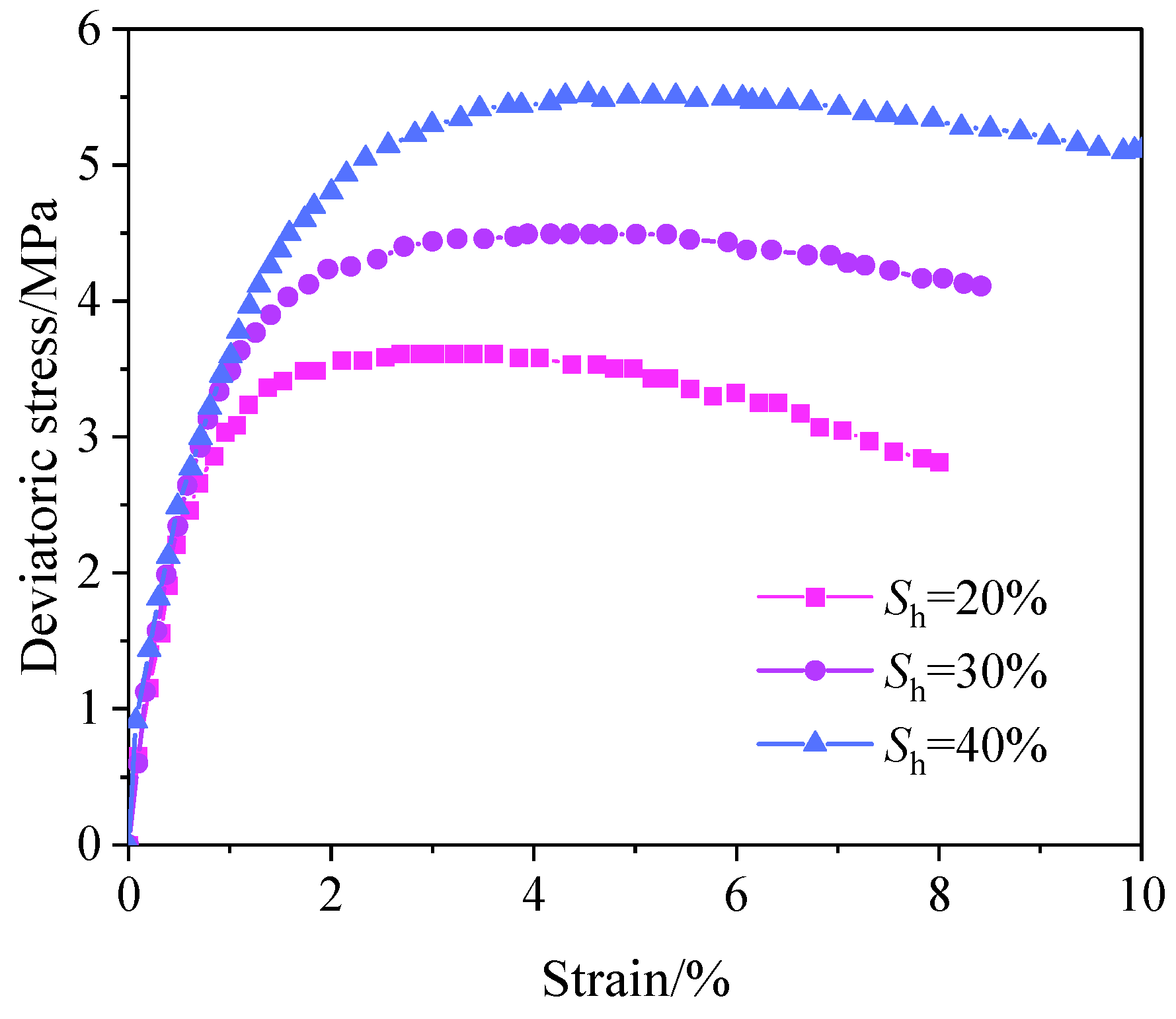
The bias stress–strain curves of HBSS at different saturation levels are shown in Figure 2. The y-axis represents the bias stress, while the x-axis represents the strain. The test results indicate that under three-dimensional stress, the HBSS specimens exhibited significant axial deformation, with peak strain generally exceeding 0.04. As the saturation degree increased, there was a corresponding rise in the peak strength of the specimens. Additionally, the residual strength of the hydrate-bearing sandy sediment (HBSS) specimens became increasingly pronounced at higher saturation levels. This trend suggests that, as the sediment became more saturated, its ability to withstand shear forces improved significantly. This observation underscores the importance of saturation in determining the mechanical properties of HBSS. Specifically, during the process of resisting sliding at the hydrate-sediment interface under applied confining pressure, the sediments developed a stable residual strength. This stable residual strength is crucial for maintaining structural integrity and stability in environments where these sediments are present.

3.2. Triaxial Creep Test Results

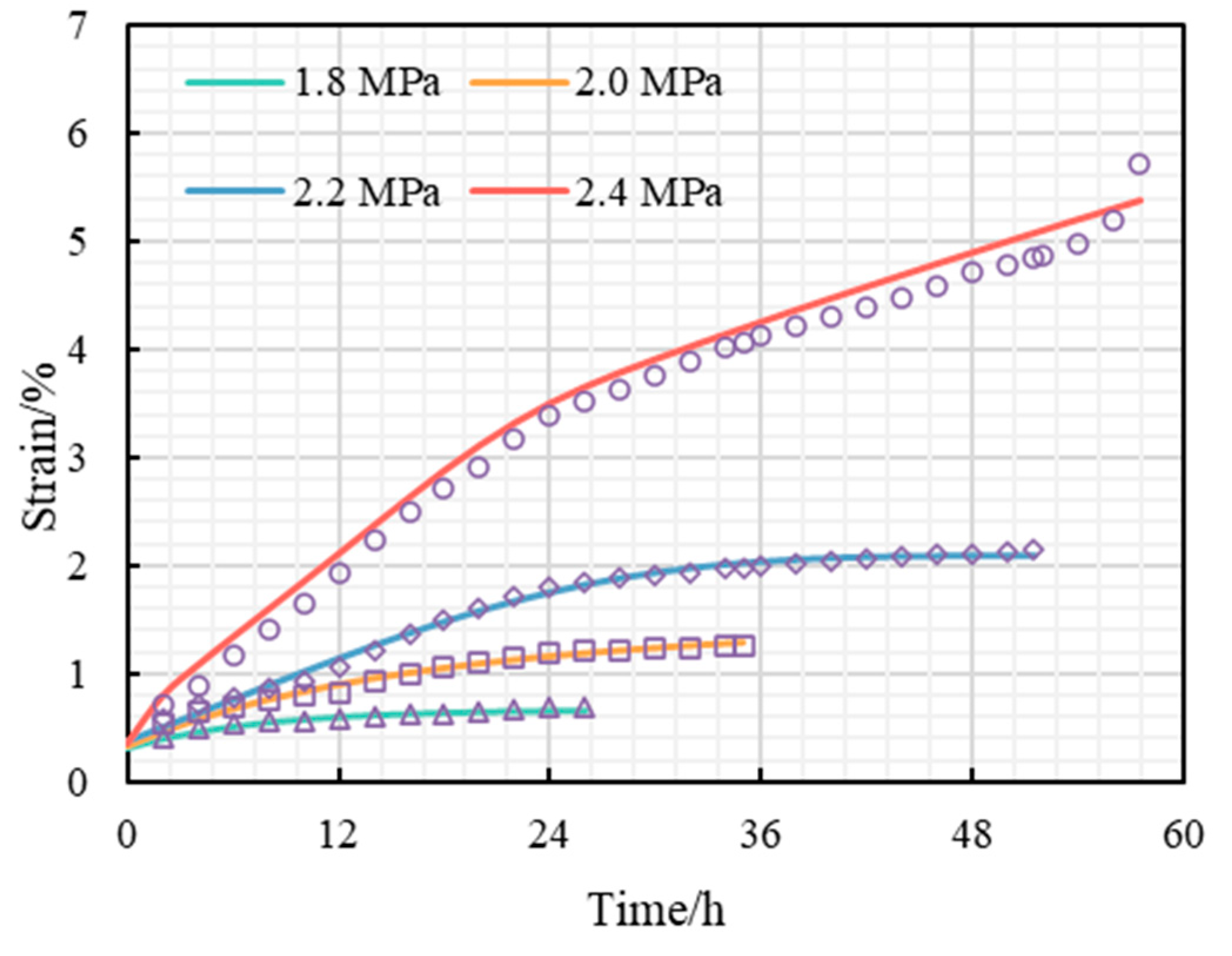
Figure 3 presents the creep curves of sandy sediments containing hydrates at various saturation degrees. The curves indicate that, under triaxial-loading conditions, the initial creep strain was relatively small and exhibits a rapid decay, which signifies the presence of a stable creep stage. This stage was characterised by a gradual deformation response to the applied load, suggesting that the sediments were able to maintain a certain level of stability despite the stress. As the axial load was increased, the creep curve transitioned from this stable creep stage to an accelerated creep stage, where the creep rate began to rise significantly. This acceleration indicates that the sediment was experiencing greater strain in response to the increased load, leading to a more pronounced deformation behaviour. Importantly, it has been observed that the amount of deformation corresponding to this accelerated creep phase decreased as the saturation level increased. This finding suggests that higher levels of hydrate saturation played a crucial role in enhancing the brittleness of the methane-containing hydrate sediments. In other words, as the saturation of the hydrate increased, the sediments became less capable of undergoing significant deformation before failure, resulting in a more brittle response.
The creep properties of sandy sediments containing hydrate sediments at different saturation levels were basically the same. Taking the 20% saturation specimen as an example, the axial strain was 0.69% after 26 h of loading at an axial load of 1.8 MPa. At an axial load of 2.0 MPa, the axial strain was 1.26% after 35 h of loading, and at an axial load of 2.2 MPa, the axial strain was 2.16% after 52 h of loading. When the axial load was 2.4 MPa, after 36 h of loading, the specimen creep rate region was stable, the axial strain was 4.13%, and after 54 h of loading, the specimen creep rate began to grow, when the axial strain was 4.95%. The specimen began to creep damage.

3.3. Long-Term Strength

The long-term strength of a hydrate-bearing sandy sediment (HBSS) deposit represents its capacity to withstand damage under prolonged loading conditions. This long-term strength serves as the stratigraphic limit strength, ensuring the safe development of hydrate resources over extended periods. Consequently, accurately calculating the long-term strength is crucial for the sustainable and secure extraction of hydrates. Several methods can be employed to calculate long-term strength, including the excessive creep method, creep rate method, and isochronous stress–strain curve method. In this study, we utilised the excessive creep method to determine the long-term strength of sandy sediments that contain hydrate. The results of these calculations are presented in Table 1. From the data shown in the table, it is evident that the long-term strength of the HBSS increased linearly as hydrate saturation rose. This finding underscores the importance of hydrate saturation in enhancing the stability and strength of the formation. Conversely, it also indicates that the long-term strength of the deposit significantly decreased when hydrate decomposition occurred. In the design of the development programme, the decrease in formation strength due to hydrate decomposition should be fully considered. The long-term strength of sandy sediments containing HBSSs is typically defined by their triaxial strength, which serves as an indicator of their strength class. This is expressed as a parameter that ignores the danger level of the effects of creep for the design of the development programme. A lower strength class also indicates a greater difference between the two and a higher risk of development after neglecting creep. As can be seen in Table 1, the intensity level of sandy sediments with hydrate sediments under different saturation was basically the same, 0.61~0.62, which indicates that the risk of geological hazards was basically the same for different saturated strata after ignoring the creep. However, it is not negligible that the difference between the two increased significantly, which indicates that the damage to the hydrate structure in the long-term loading process was the main factor causing the strength decline.

4. Description of Full Creep Regions in HBSS: A New Creep Constitutive Model

From the creep curves of the HBSSs, it is obvious that they have accelerated creep. Therefore, we developed a new nonlinear creep constitutive model by concatenating the Burgers model with a fractional-order viscoplastic body model.

4.1. One-Dimensional Creep Constitutive Model

4.1.1. Fractional-Order Viscoplastic Body Models

In linear viscoelastic theory, the mechanical analogue of a purely elastic solid can be represented by a spring, and the mechanical analogue of a purely viscous fluid can be represented by a damper. Various combination models (e.g., Maxwell’s model, Kevin’s model) can be obtained by connecting the two in series and in parallel to derive the corresponding strain-versus-time relationship. For elastic and viscous units, Hooke’s and Newton’s laws are obeyed. From the derivative point of view, it can be expressed as follows:
σ t = E d 0 ε t d t 0 σ t = η d 1 ε t d t 1
where σ(t) is the stress; ε(t) is the strain; E is the modulus of elasticity of the spring; and η is the coefficient of the viscosity of the viscous element.
For elastic solids, the stress is proportional to the zero-order derivative of the strain, which means the stress is directly proportional to the strain itself. For viscous bodies, the stress is proportional to the first-order derivative of the strain, which means the stress is proportional to the rate of change in the strain, or the strain rate. The stress and strain of a viscoelastic body is intermediate between that of a purely elastic solid and that of a purely viscous fluid, i.e., the stress is proportional to a non-integer of the strain. The intrinsic equation of a viscoelastic body can be described as follows:
σ t = η d a ε t d t a 0 a 1
where a is the fractional order and the above equation is known as the Scott–Blair fractional-order component.
Based on the Rieman–Liouville fractional-order calculus theory, the creep constitutive model can be expressed as follows:
D t a 0 f t = d a ε t d t a = 1 Γ a a t t τ a 1 f τ d τ
Differential transformations are obtained:
D t a 0 f t = d a ε t d t a = 1 Γ n a d d t n a t f τ t τ a n + 1 d τ
where 0 D t a is the fractional-order derivative operator; t is the time variable; n is the smallest integer greater than a; f(t) is a function of time; and Γ is the Gamma function, defined as follows:
Γ z = 0 e x x z 1 d x ( R e z > 0 )
where a precondition for the equation to hold, z is a complex number with real part greater than 0. That is, Re(z) > 0.
When σ(t) is constant, it can be back-calculated from the Rieman–Liouville fractional-order calculus:
ε t = σ η t a Γ 1 + a 0 < a < 1
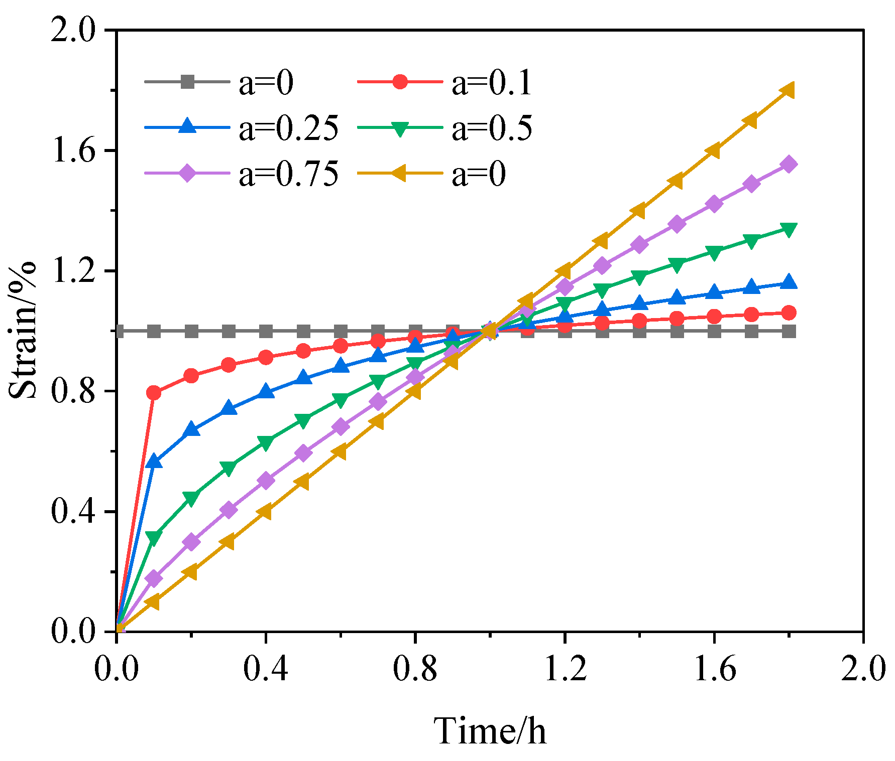
When σ and η are set to the same value, different fractional-order creep curves are shown in Figure 4. The figure illustrates that as the fractional order (a) gradually increases to one, the creep behaviour of the fractional-order viscoplastic body becomes increasingly consistent with the creep curve of a Newtonian body. Conversely, as the fractional order (a) decreases step by step to zero, the creep curve of the fractional-order viscoplastic body approaches the creep curve of an elastic element. Between zero and one, the strain characteristics expressed by the fractional-order viscoplastic body are not like the strain of the elastic element that is constant with time, nor like the strain of the Newtonian body that shows a linear relationship with time, but show a nonlinear increment. The creep curves at different creep rates and stress levels can be reflected by setting different parameters. When both σ and η are assigned the same value, a variety of fractional-order creep curves emerge, as depicted in Figure 4. This figure demonstrates that as the fractional order (a) gradually approaches one, the creep behaviour of the fractional-order viscoplastic body increasingly aligns with the creep curve typical of a Newtonian fluid. This indicates that, at this stage, the sediment exhibits characteristics similar to those of a classic Newtonian body, where the strain response is linear over time. On the other hand, as the fractional order (a) is systematically reduced to zero, the creep curve of the fractional-order viscoplastic body begins to resemble that of an elastic element. In this scenario, the sediment behaves in a more rigid manner, with strain characteristics that are distinctly different from those of a viscous fluid. Importantly, for values between zero and one, the strain behaviour demonstrated by the fractional-order viscoplastic body is neither consistent with the constant strain behaviour of an elastic element over time nor with the linear strain behaviour of a Newtonian body. Instead, it exhibits a nonlinear increment, reflecting a more complex relationship between stress and strain. This unique response underscores the versatility of the fractional-order model in capturing a wide range of sediment behaviours. Moreover, by adjusting various parameters, the creep curves can be tailored to represent different creep rates and stress levels, thereby allowing for a comprehensive analysis of the sediment’s performance under diverse conditions. This flexibility makes the fractional-order viscoplastic model a powerful tool for studying the creep characteristics of sediments across different loading scenarios.

4.1.2. Nonlinearisation of Viscous Elements

In the creep-element model, the creep parameter is constant and cannot qualitatively describe the nonlinear properties of HBSS. During decelerated creep, the viscosity coefficient of HBSS increases with time. Therefore, the viscosity coefficient in the Kelvin model is assumed to be a function of time as shown in Equation (7):
η t = η 1 e λ t
where η is the viscosity coefficient of the viscous element, in MPa·h, and λ is the creep parameter, in dimensionless.
The derivatives of Equation (7) are executed to obtain the first-order derivative equation of the viscous parameter as shown in Equation (8).
η ˙ t = η 1 λ e λ t
The modified viscosity parameters were substituted into the Kelvin model to obtain the modified eigenstructural equations as shown in Equation (9):
σ = E 1 ε + η t ε ˙
where σ is the stress, in MPa, E1 is the elastic model, in MPa, and ε is the creep strain, in dimensionless.
This is obtained by substituting Equation (8) into Equation (9) and solving the differential equation.
ε 1 = σ E 1 A E 1 exp E 1 η λ e λ t + B E 1
Substituting the boundary conditions t = 0 and ε = 0 into Equation (10) yields the modified Kelvin model creep equation as shown in Equation (11).
ε 1 = σ E 1 1 exp E 1 e λ t 1 η 1 λ

4.1.3. Fractional-Order Nonlinear Creep Modelling

A nonlinear fractional-order creep model (Figure 5) was developed by connecting the Burgers model in series with the fractional-order viscoplastic body model, which can comprehensively describe the nonlinear creep characteristics of HBSS. The model includes a Kelvin body (I), a nonlinear Maxwell body (II), and a fractional-order viscoplastic body (III).
The Kelvin body model creep equation, as shown in Equation (12).
ε 0 = σ E 0 + σ η 0 t
The fractional-order nonlinear creep model is obtained by superimposing Equations (6), (11) and (12) as shown in Equation (13):
ε t = σ E 0 + σ η 0 t + σ E 1 1 exp E 1 e λ t 1 η 1 λ , σ < σ s ε t = σ E 0 + σ η 0 t + σ E 1 1 exp E 1 e λ t 1 η 1 λ + σ σ s η 2 t a Γ 1 + a , σ σ s
where E0 is the instantaneous modulus of elasticity, in MPa.

4.2. Three-Dimensional Creep Constitutive Model

In the three-dimensional stress state, the stress tensor inside the material can be decomposed into the spherical stress tensor σm and the deviatoric stress tensor Sij, which are expressed as follows:
σ m = 1 3 σ 1 + σ 2 + σ 3 = 1 3 σ k k S i j = σ i j δ i j σ m = σ i j 1 3 δ i j σ k k
where δij is the Kronecker function. It is generally accepted that the spherical stress tensor can only change the volume of the material but not its shape. And the bias stress tensor Sij can only cause shape change. Similarly, the strain tensor can be decomposed into the ball strain tensor εm and the bias strain tensor eij accordingly, with the expression:
ε m = 1 3 ε 1 + ε 2 + ε 3 = 1 3 ε k k e i j = ε i j δ i j ε m = ε i j 1 3 δ i j ε k k
From the above equation:
ε i j = e i j + δ i j ε m
For the three-dimensional stress state the Hook body has
σ m = 3 K ε m S i j = 2 G e i j
where K is the bulk modulus and G is the shear modulus. To satisfy the isotropic conditions of the material, it is assumed that the elastic strain is caused by the spherical stress tensor, while the creep is caused by the deviatoric stress tensor. The creep equation of the material under a three-dimensional stress state is
ε m = σ m 3 K e i j = S i j 2 G 1 + S i j 2 η 1 t + S i j 2 G 2 1 exp G 2 η 2 t
where G1, G2 is the shear modulus. K, G1, G2, η1, and η2 are model parameters, which are determined by fitting the test results.
Maxwell body in a three-dimensional state of stress:
e i j M = S i j 2 G 0 + S i j 2 H 0 t
Kelvin body in a three-dimensional state of stress:
e i j K = S i j 2 G 2 1 exp G 2 H 2 t
Fractional-order viscoplastic bodies under three-dimensional stress states:
e i j L = S i j σ s 2 H 2 t a Γ 1 + a
Superimposing Equations (19)–(21), the total strain in three-dimensional stress is obtained and can be expressed as Equation (22).
ε t = S i j 2 G 0 + S i j 2 H 0 t + σ m δ i j 3 K 0 + S i j 2 G 1 1 exp G 1 e λ t 1 H 1 λ , σ < σ s ε t = S i j 2 G 0 + S i j 2 H 0 t + σ m δ i j 3 K 0 + S i j 2 G 1 1 exp G 1 e λ t 1 H 1 λ + S i j σ s 2 H 2 t a Γ 1 + a , σ σ s
According to the theory of plastic mechanics, we can obtain the following relationship:
S i j = σ i j σ m δ i j σ m = 1 3 σ 1 + σ 2 + σ 3
where σm is the average stress, in MPa, σ1, σ2 and σ3 are the first, second, and third principal stresses, in MPa, respectively.
In the conventional triaxial test, σ2 = σ3 and Equation (23) is deformed as Equation (24) (Liu et al.) [38].
S 11 = 2 3 σ 1 σ 3 σ m = 1 3 σ 1 + 2 σ 3
Bringing Equation (24) into Equation (22), the HBSS three-dimensional creep constitutive equation is obtained as Equation (25).
ε t = σ 1 σ 3 3 G 0 + σ 1 σ 3 3 H 0 + σ 1 + 2 σ 3 9 K 0 + σ 1 σ 3 3 G 1 1 exp G 1 e λ t 1 H 1 λ , σ 1 σ 3 < σ s ε t = σ 1 σ 3 3 G 0 + σ 1 σ 3 3 H 0 + σ 1 + 2 σ 3 9 K 0 + σ 1 σ 3 3 G 1 1 exp G 1 e λ t 1 H 1 λ + σ 1 σ 3 σ s 3 H 2 t + σ 1 σ 3 σ s 3 G 2 t a Γ 1 + a , σ 1 σ 3 σ s

4.3. Model Parameter Identification

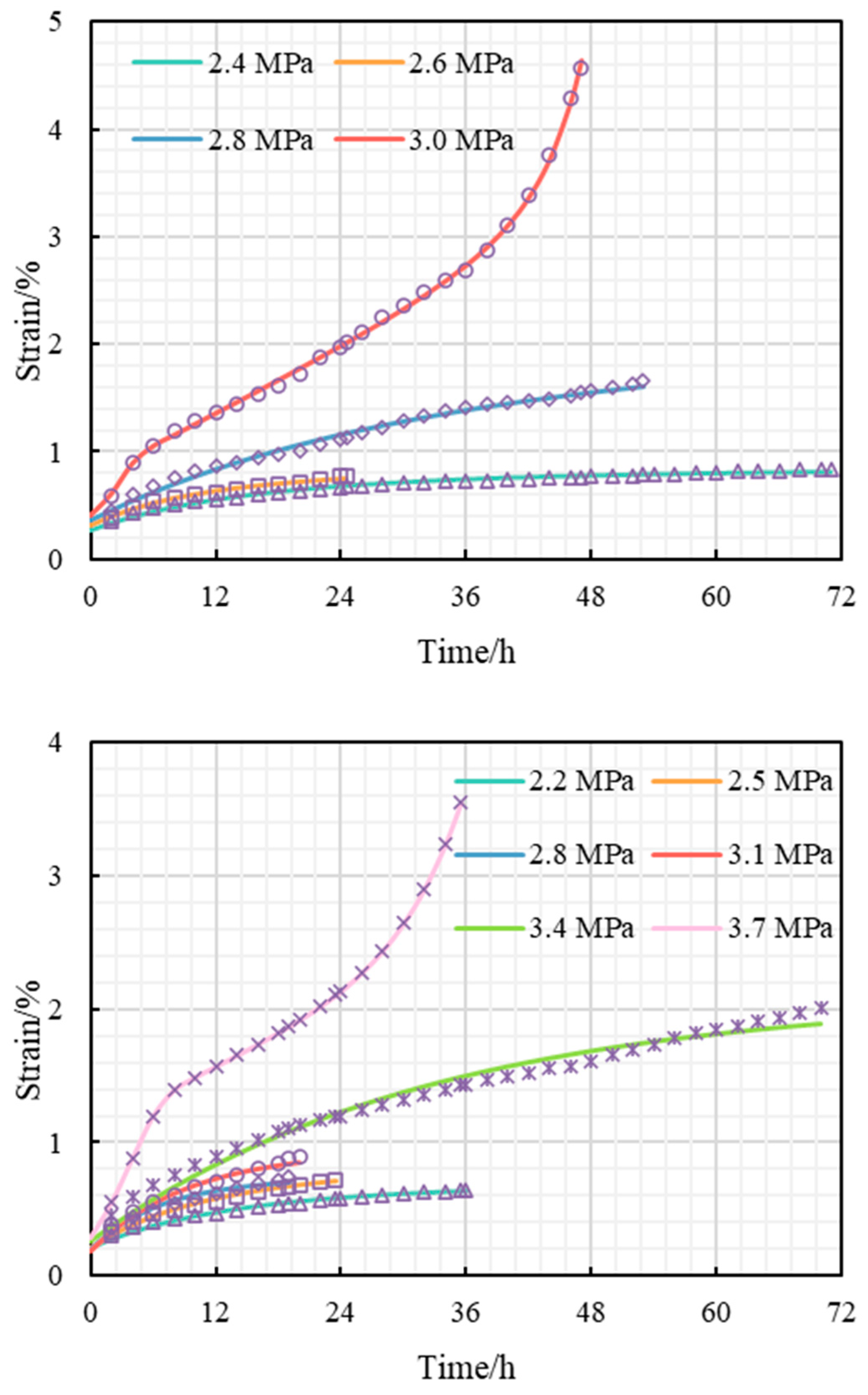
In this study, we utilised a planned solution function for nonlinear regression analysis. By fitting the creep curve, we were able to obtain the parameters for the optimal fractional-order nonlinear creep model specific to hydrate-bearing sandy sediments (HBSSs), as shown in Table 2. The results of the curve fitting for the experimental data are presented in Figure 6. In Figure 6, the solid line illustrates the fitting results, while the scattered points correspond to the experimental data depicted in Figure 3. Remarkably, the average correlation coefficient for the model’s fit reaches a high value of 0.98. This strong correlation indicates that the parameters in Table 2 effectively represent the creep behaviour of HBSSs throughout all testing stages.

4.4. Model Verification

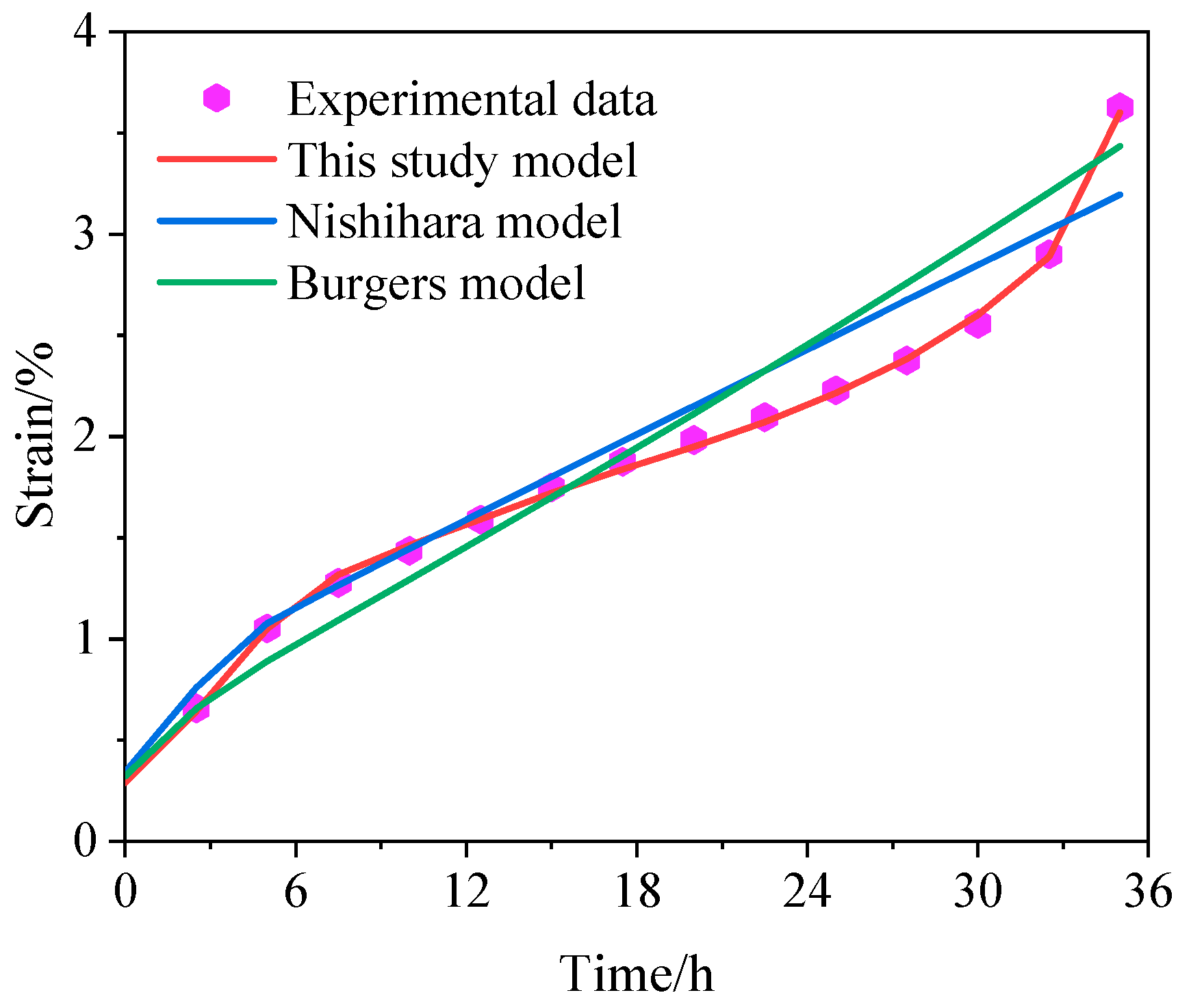
The model comparison work is based on the experimental data of creep strain with a saturation of 40%. We compared the model developed in this study with the Nishihara model and the Burgers model. The calculation results are shown in Figure 7. The fit correlation coefficient of the Nishihara model to the experimental data was 0.971, and the fit correlation coefficient of the Burgess model to the experimental data was 0.971. Both of them were smaller than the fit correlation coefficients of the models developed in this study, which were 0.989. It can be seen that the model developed in this study can better express the nonlinear acceleration behaviour of the HBSS, and is more suitable for conducting the deformation analysis of the HBSS [39].

5. Conclusions and Prospects

The long-term strength of HBSS is measured by their triaxial strength, which shows their strength class. A lower strength class means a bigger difference and higher risk if creep is ignored. The strength of sandy sediments with hydrates is similar under different saturation levels, indicating similar geological hazard risks. However, the difference between the two increases significantly, suggesting that damage to the hydrate structure during long-term loading is the main cause of strength decline.
This study creatively introduces the fractional-order nonlinear creep model by utilising the Riemann–Liouville fractional calculus framework and nonlinear damage theory, aiming to accurately determine the damage characteristic structure under three-dimensional stress conditions. To verify the effectiveness and reliability of this model, we apply it to the fracturing stage of the nonlinear creep model and compare it with the triaxial creep experimental results. The results show a high degree of consistency between the two, thus fully demonstrating the accuracy and reliability of this model in practical applications.
This study compares a new model with the traditional Burgers model and the Nishihara model in terms of their ability to replicate the creep behaviour of HBSS. Through comparative analysis, the new model exhibits significant advantages over the other two models in replicating the creep behaviour.
However, there are still deficiencies in this study, such as the lack of correlation equations between model parameters and saturation/stress, etc., and the inability of the model to be extended for applications. These are limited by the size of the experimental sample. In the next step, we will carry out more experiments to enrich the parameter samples, establish the relationship between the saturation/stress and the model parameters, and improve the applicability and dexterity of using the model.

Author Contributions

Methodology, S.S.; validation, Y.Z. and X.Z.; formal analysis, X.Z.; writing—original draft preparation, S.S.; writing—review and editing, Y.Z. All authors have read and agreed to the published version of the manuscript.

Funding

This research was funded by Open-ended Fund of State Key Laboratory of National Gas Hydrates (Grant No. 2022-FKJJ-SHW).

Data Availability Statement

Data is contained within the article.

Conflicts of Interest

Authors Xiaohan Zhang and Yunjian Zhou were employed by the company CNOOC Research Institute Co., Ltd. The remaining authors declare that the research was conducted in the absence of any commercial or financial relationships that could be construed as a potential conflict of interest.

References

  1. Li, A.; Deng, H.; Zhang, H.; Jiang, M.; Liu, H.; Xiao, Y.; Wen, J. Developing a Two-Step Improved Damage Creep Constitutive Model Based on Soft Rock Saturation-Loss Cycle Triaxial Creep Test. Nat. Hazards 2021, 108, 2265–2281. [Google Scholar] [CrossRef]
  2. Li, Y.; Liu, L.; Jin, Y.; Wu, N. Characterization and Development of Marine Natural Gas Hydrate Reservoirs in Clayey-Silt Sediments: A Review and Discussion. Adv. Geo-Energy Res. 2021, 5, 75–86. [Google Scholar] [CrossRef]
  3. Wu, P.; Li, Y.; Wang, L.; Wang, L.; Sun, X.; Liu, W.; Song, Y. Triaxial Tests on the Overconsolidated Methane Hydrate-Bearing Clayey-Silty Sediments. J. Pet. Sci. Eng. 2021, 206, 109035. [Google Scholar] [CrossRef]
  4. Dong, L.; Li, Y.; Liao, H.; Liu, C.; Chen, Q.; Hu, G.; Liu, L.; Meng, Q. Strength Estimation for Hydrate-Bearing Sediments Based on Triaxial Shearing Tests. J. Pet. Sci. Eng. 2020, 184, 106478. [Google Scholar] [CrossRef]
  5. Li, J.; Ye, J.; Qin, X.; Qiu, H.; Wu, N.; Lu, H.; Xie, W.; Lu, J.; Peng, F.; Xu, Z.; et al. The First Offshore Natural Gas Hydrate Production Test in South China Sea. China Geol. 2018, 1, 5–16. [Google Scholar] [CrossRef]
  6. Priest, J.A.; Hayley, J.L. Strength of Laboratory Synthesized Hydrate-Bearing Sands and Their Relationship to Natural Hydrate-Bearing Sediments. JGR Solid. Earth 2019, 124, 12556–12575. [Google Scholar] [CrossRef]
  7. Sun, X.; Yao, D.; Qu, J.; Sun, S.; Qin, Z.; Tao, L.; Zhao, Y. A Novel Transient Hole Cleaning Algorithm for Horizontal Wells Based on Drift-Flux Model. Geoenergy Sci. Eng. 2024, 233, 212517. [Google Scholar] [CrossRef]
  8. Morshedifard, A.; Masoumi, S.; Abdolhosseini Qomi, M.J. Nanoscale Origins of Creep in Calcium Silicate Hydrates. Nat. Commun. 2018, 9, 1785. [Google Scholar] [CrossRef]
  9. Zhu, Y.; Chen, C.; Luo, T.; Song, Y.; Li, Y. Creep Behaviours of Methane Hydrate-Bearing Sediments. Environ. Geotech. 2019, 9, 199–209. [Google Scholar] [CrossRef]
  10. Königsberger, M.; Irfan-Ul-Hassan, M.; Pichler, B.; Hellmich, C. Downscaling Based Identification of Nonaging Power-Law Creep of Cement Hydrates. J. Eng. Mech. 2016, 142, 04016106. [Google Scholar] [CrossRef]
  11. Sun, X.; Luo, T.; Wang, L.; Wang, H.; Song, Y.; Li, Y. Numerical Simulation of Gas Recovery from a Low-Permeability Hydrate Reservoir by Depressurization. Appl. Energy 2019, 250, 7–18. [Google Scholar] [CrossRef]
  12. Lei, L.; Seol, Y. Pore-Scale Investigation Of Methane Hydrate-Bearing Sediments Under Triaxial Condition. Geophys. Res. Lett. 2020, 47. [Google Scholar] [CrossRef]
  13. Gao, Y.; Chen, Y.; Zhao, X.; Wang, Z.; Li, H.; Sun, B. Risk Analysis on the Blowout in Deepwater Drilling When Encountering Hydrate-Bearing Reservoir. Ocean. Eng. 2018, 170, 1–5. [Google Scholar] [CrossRef]
  14. Fereidounpour, A.; Vatani, A. An Investigation of Interaction of Drilling Fluids with Gas Hydrates in Drilling Hydrate Bearing Sediments. J. Nat. Gas. Sci. Eng. 2014, 20, 422–427. [Google Scholar] [CrossRef]
  15. Li, Y.; Liu, C.; Liu, L.; Sun, J.; Liu, H.; Meng, Q. Experimental Study on Evolution Behaviors of Triaxial-Shearing Parameters for Hydrate-Bearing Intermediate Fine Sediment. Adv. Geo-Energy Res. 2018, 2, 43–52. [Google Scholar] [CrossRef]
  16. Miyazaki, K.; Yamaguchi, T.; Sakamoto, Y.; Aoki, K. Time-Dependent Behaviors of Methane-Hydrate Bearing Sediments in Triaxial Compression Test. Int. J. JCRM 2011, 7, 43–48. [Google Scholar] [CrossRef]
  17. Hu, Q.; Li, Y.; Sun, X.; Chen, M.; Bu, Q.; Gong, B. Integrating Test Device and Method for Creep Failure and Ultrasonic Response of Methane Hydrate-Bearing Sediments. Rev. Sci. Instrum. 2023, 94, 025105. [Google Scholar] [CrossRef]
  18. Zhu, Z.; Luo, F.; Zhang, Y.; Zhang, D.; He, J. A Creep Model for Frozen Sand of Qinghai-Tibet Based on Nishihara Model. Cold Reg. Sci. Technol. 2019, 167, 102843. [Google Scholar] [CrossRef]
  19. Deng, H.; Dai, G.; Azadi, M.R.; Hu, Y. Drained Creep Test and Creep Model Evaluation of Coastal Soft Clay. Indian Geotech. J. 2021, 51, 1283–1298. [Google Scholar] [CrossRef]
  20. Liu, B.; Zhan, L.; Lu, H.; Zhang, J. Advances in Characterizing Gas Hydrate Formation in Sediments with NMR Transverse Relaxation Time. Water 2022, 14, 330. [Google Scholar] [CrossRef]
  21. Wu, Q.; Lin, N.; Li, L.; Chen, F.; Zhang, B.; Wu, Q.; Xv, X.; Wang, X. Experimental Study on the Kinetics of the Natural Gas Hydration Process with a NiMnGa Micro-/Nanofluid in a Static Suspension System. Water 2022, 14, 1–17. [Google Scholar] [CrossRef]
  22. Lin, H.; Zhang, X.; Wang, Y.; Yong, R.; Fan, X.; Du, S.; Zhao, Y. Improved Nonlinear Nishihara Shear Creep Model with Variable Parameters for Rock-Like Materials. Adv. Civ. Eng. 2020, 2020, 7302141. [Google Scholar] [CrossRef]
  23. Li, G.; Wang, Y.; Hu, Y.; Wang, D.; Yang, X.; Li, Y.; Zhou, Z.; Zhang, S. Shear Creep Mechanical Properties and Damage Model of Mudstone in Open-Pit Coal Mine. Sci. Rep. 2022, 12, 5148. [Google Scholar] [CrossRef]
  24. Zhou, H.W.; Wang, C.P.; Han, B.B.; Duan, Z.Q. A Creep Constitutive Model for Salt Rock Based on Fractional Derivatives. Int. J. Rock Mech. Min. Sci. 2011, 48, 116–121. [Google Scholar] [CrossRef]
  25. Yan, B.; Guo, Q.; Ren, F.; Cai, M. Modified Nishihara Model and Experimental Verification of Deep Rock Mass under the Water-Rock Interaction. Int. J. Rock Mech. Min. Sci. 2020, 128, 104250. [Google Scholar] [CrossRef]
  26. Cheng, H.; Zhang, Y.; Zhou, X. Nonlinear Creep Model for Rocks Considering Damage Evolution Based on the Modified Nishihara Model. Int. J. Geomech. 2021, 21, 04021137. [Google Scholar] [CrossRef]
  27. Liu, J.; Wu, F.; Zou, Q.; Chen, J.; Ren, S.; Zhang, C. A Variable-Order Fractional Derivative Creep Constitutive Model of Salt Rock Based on the Damage Effect. Geomech. Geophys. Geo-Energ. Geo-Resour. 2021, 7, 46. [Google Scholar] [CrossRef]
  28. Chen, M.; Li, Y.; Zhang, Y.; Qi, M.; Wu, N. Recent Advances in Creep Behaviors Characterization for Hydrate-Bearing Sediment. Renew. Sustain. Energy Rev. 2023, 183, 113434. [Google Scholar] [CrossRef]
  29. Li, Y.; Hu, Q.; Wu, N.; Wang, H.; Sun, X.; Hu, G.; Sun, Z.; Jiang, Y. Acoustic Characterization for Creep Behaviors of Marine Sandy Hydrate-Bearing Sediment. Sci. Rep. 2023, 13, 22199. [Google Scholar] [CrossRef]
  30. Liu, X.; Liu, L.; Li, Z.; Yao, Z. Experimental Analysis on Creep Properties of Frozen Silty Mudstone Considering Conservation of Energy. J. Test. Eval. 2021, 49, 417–434. [Google Scholar] [CrossRef]
  31. Liu, W.; Zhou, H.; Zhang, S.; Jiang, S.; Yang, L. A Nonlinear Creep Model for Surrounding Rocks of Tunnels Based on Kinetic Energy Theorem. J. Rock Mech. Geotech. Eng. 2023, 15, 363–374. [Google Scholar] [CrossRef]
  32. Chen, W.; Wan, W.; Xie, S.; Kuang, W.; Peng, W.; Wu, Q.; Tong, S.; Wang, X.; Tang, X. Features and Constitutive Model of Gypsum’s Uniaxial Creep Damage Considering Acidization. Geofluids 2020, 2020, 8874403. [Google Scholar] [CrossRef]
  33. Nguyen, N.N.; Nguyen, A.V.; Dang, L.X. The Inhibition of Methane Hydrate Formation by Water Alignment underneath Surface Adsorption of Surfactants. Fuel 2017, 197, 488–496. [Google Scholar] [CrossRef]
  34. Shan, R.; Bai, Y.; Ju, Y.; Han, T.; Dou, H.; Li, Z. Study on the Triaxial Unloading Creep Mechanical Properties and Damage Constitutive Model of Red Sandstone Containing a Single Ice-Filled Flaw. Rock Mech. Rock Eng. 2021, 54, 833–855. [Google Scholar] [CrossRef]
  35. Shukla, A.; Joshi, Y.M. Boltzmann Superposition Principle for a Time-Dependent Soft Material: Assessment under Creep Flow Field. Rheol. Acta 2017, 56, 927–940. [Google Scholar] [CrossRef]
  36. Qin, X.; Liang, Q.; Ye, J.; Yang, L.; Qiu, H.; Xie, W.; Liang, J.; Lu, J.; Lu, C.; Lu, H.; et al. The Response of Temperature and Pressure of Hydrate Reservoirs in the First Gas Hydrate Production Test in South China Sea. Appl. Energy 2020, 278, 115649. [Google Scholar] [CrossRef]
  37. Yamamoto, K.; Wang, X.-X.; Tamaki, M.; Suzuki, K. The Second Offshore Production of Methane Hydrate in the Nankai Trough and Gas Production Behavior from a Heterogeneous Methane Hydrate Reservoir. RSC Adv. 2019, 9, 25987–26013. [Google Scholar] [CrossRef]
  38. Liu, H.Z.; Xie, H.Q.; He, J.D.; Xiao, M.L.; Zhuo, L. Nonlinear Creep Damage Constitutive Model for Soft Rocks. Mech. Time-Depend. Mater. 2017, 21, 73–96. [Google Scholar] [CrossRef]
  39. Tian, Z.; Liu, Y.; Zhang, X.; Zhang, Y.; Zhang, M. Formation Mechanisms and Characteristics of the Marine Nepheloid Layer: A Review. Water 2022, 14, 678. [Google Scholar] [CrossRef]
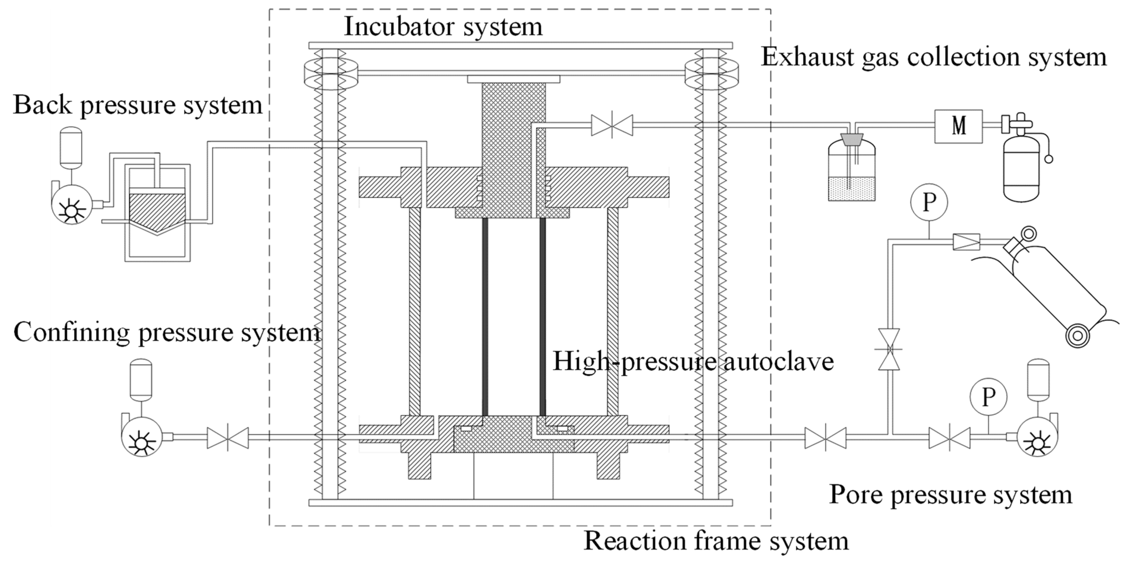
Figure 1. Testing device structural diagram of HBSS (M is the flow meter, P is the pressure gauge).
Water 16 02947 g001
Figure 2. Deviatoric stress–strain curves under different hydrate saturation (20%, 30%, and 40%) of HBSS.
Water 16 02947 g002
Figure 3. Triaxial creep curves of HBSS (From Ref. [29]).
Water 16 02947 g003
Figure 4. Creep strain variation curves of fractional-order viscoplastic body with different fractional-order parameters (a).
Water 16 02947 g004
Figure 5. The mechanical model of the HBSS nonlinear creep constitutive model. (I) Kelvin body, (II) nonlinear Maxwell body, (III) fractional-order viscoplastic body.
Water 16 02947 g005
Figure 6. The curve fitting for the experimental data.
Water 16 02947 g006aWater 16 02947 g006b
Figure 7. Comparison of this study model with the Nishihara model and Burgers model calculations.
Water 16 02947 g007
Table 1. Creep test stress path.
Sh/%Long-Term Strength/MPaTriaxial Strength/MPaStrength Level
202.23.610.61
302.84.490.62
403.45.520.62
Table 2. Model parameter fitting results.
Sh/%σ1σ3
/MPa
G0
/MPa
K0
/MPa
H0
/MPa·h
G1
/MPa
λ
/10−2
H1
/MPa·h
H2
/MPa·h
G2
/MPa
aR2
201.836542524151680.011235///0.984
2456431121440−3.59942///0.982
2.24294261240434.611159///0.995
2.445644224057513.1542084293.640.630.999
302.414341664461119−2.822183///0.997
2.69961061530127−4.391819///0.994
2.82246206332839−1.521920///0.995
312701060102219455.5912321327.938.010.999
402.2812799137571−5.602127///0.995
2.59418771727103−4.351572///0.994
2.8107195521131760.011203///0.984
3.11264109924571360.011277///0.990
3.414771366898620.011976///0.999
3.76382400191415535.2417542495.666.430.989
Disclaimer/Publisher’s Note: The statements, opinions and data contained in all publications are solely those of the individual author(s) and contributor(s) and not of MDPI and/or the editor(s). MDPI and/or the editor(s) disclaim responsibility for any injury to people or property resulting from any ideas, methods, instructions or products referred to in the content.