
Influence of Scour Protection on the Vertical Bearing Behaviour of Monopiles in Sand

 ,
, 
 and
and 
Abstract
1. Introduction
2. Centrifuge Modelling
2.1. Model Pile and Soil Characterisation
2.2. Centrifuge Loading Technique and Test Program
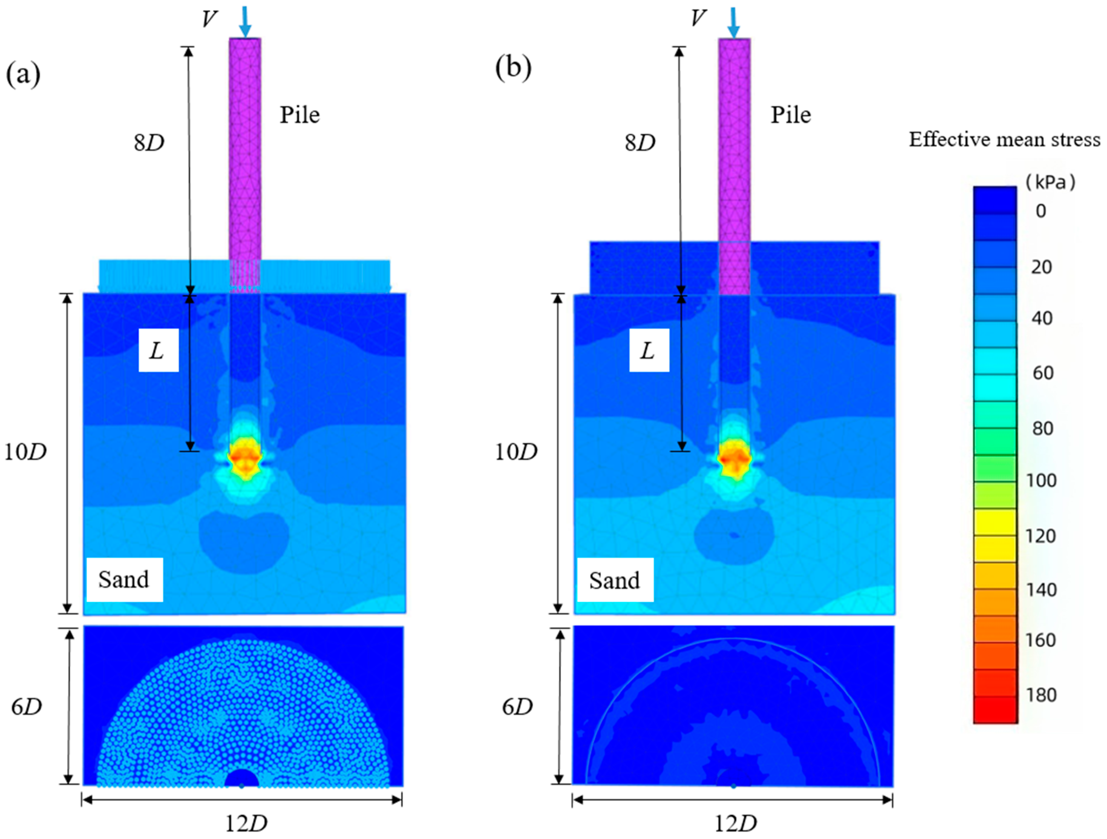
3. Finite Element Analysis
3.1. Mesh Details
3.2. Material Properties
3.3. Parametric Case Studies
4. Interpretation of Measured and Computed Results
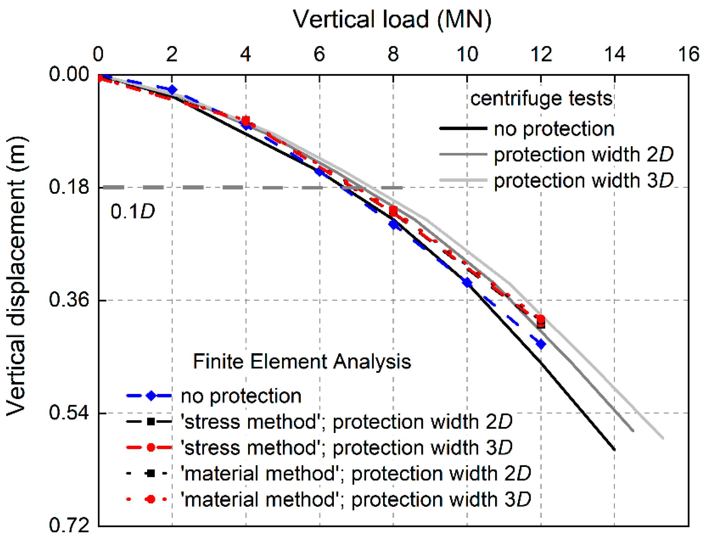
4.1. Influence of Scour Protection on Vertical Load–Vertical Displacement Relationships
4.2. Influence of Scour Protection on Vertical Capacity
4.3. Integration of ‘Stress Method’ and ‘Material Method’ in Evaluation of Scour Protection Effect on Pile Vertical Loading Behaviour
4.4. Designing Example
5. Conclusions
- Scour protection can increase the vertical capacity of the pile. At a scour protection width of 2D and an applied scour protection pressure of 30 kPa, the vertical capacity of the pile increases by 8% compared with that in the absence of scour protection.
- The scour protection material can not only provide the subsoil overburden pressure but also directly create vertical resistance to the pile structure. By using the ‘material method’, the added protection material plays a role in enlarging the embedment length of the pile, making the Vertical Capacity Increase Ratio under the ‘material method’ about 2.6% larger than that obtained using the ‘stress method’.
- The contact coefficient δ in the ‘material method’ could be incorporated into the design methodology of the pile to reflect and compare the effectiveness in increasing the vertical capacity between the ‘material method’ and ‘stress method’. The centrifuge tests and FEA results show good agreement, which proves the reliability of calibrated material parameters of the HS model.
6. Limitations
Author Contributions
Funding
Data Availability Statement
Acknowledgments
Conflicts of Interest
List of Notation
| CU | uniformity coefficient of sand | reference stress for stiffness | |
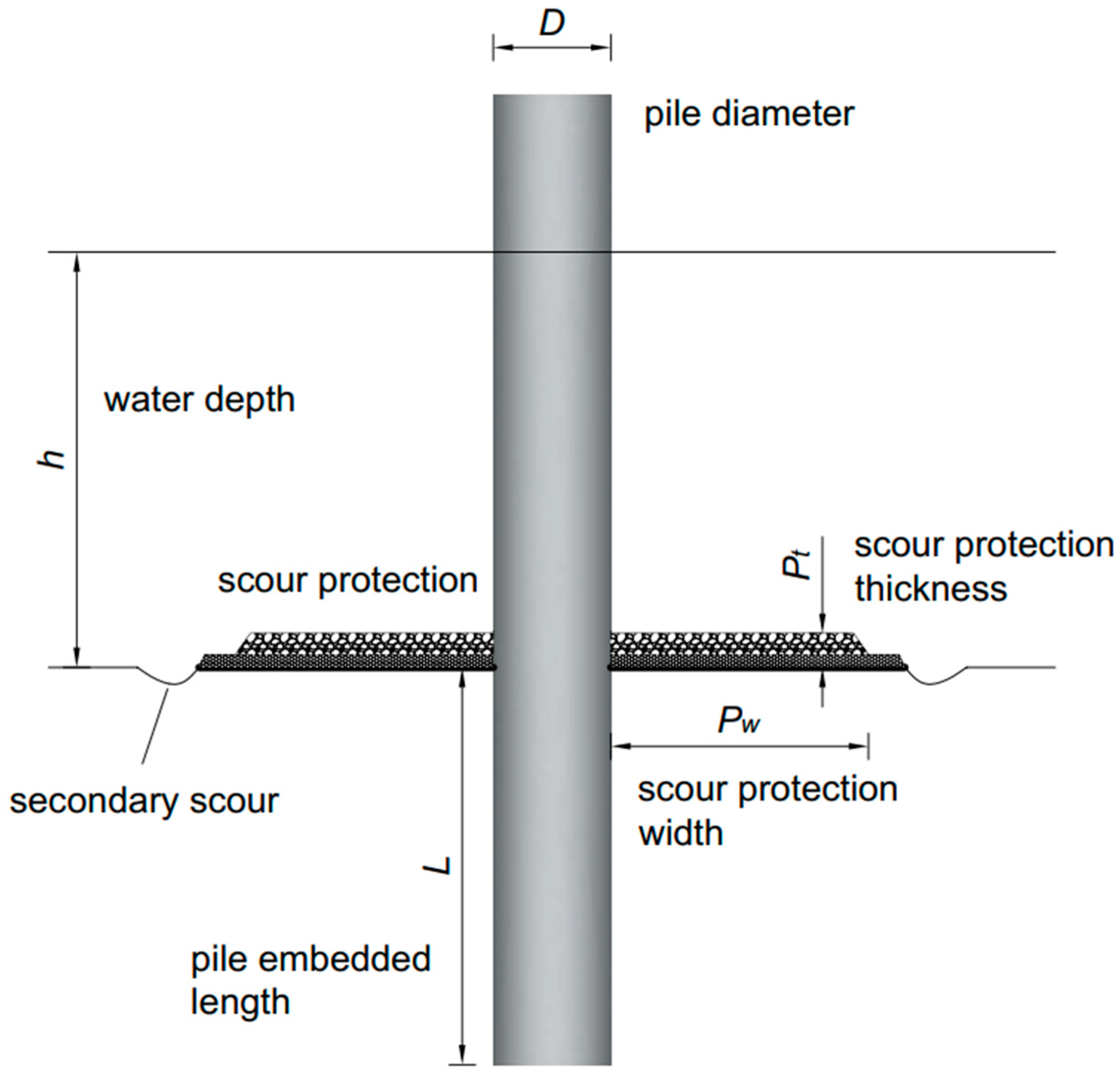
| (effective) cohesion | Pt | scour protection thickness | |
| D | pile outer diameter | equivalent scour protection pressure | |
| D50 | average grain size of sand | Pw | scour protection width |
| Dr | relative density of sand | failure ratio | |
| Ds | scour depth | t | pile wall thickness |
| E | Young’s modulus | actual vertical capacity under scour protection | |
| secant stiffness for CD triaxial test | vertical capacity without scour protection | ||
| tangent oedometer stiffness | V | vertical load | |
| unloading reloading stiffness | γ | unit weight of sand | |
| e | loading eccentricity | δ | ‘material method’ contact coefficient |
| emax | maximum void ratio of sand | ψ | angle of dilation |
| emin | minimum void ratio of sand | vertical reinforcement factor | |
| g | gravitational acceleration rate | (effective) angle of internal friction | |
| Vertical Capacity Increase Ratio by ‘material method’ | ν | Poisson’s ratio | |
| Vertical Capacity Increase Ratio by ‘stress method’ | Poisson’s ratio for unloading–reloading | ||
| h | water depth | FEA | Finite Element Analysis |
| —value for normal consolidation | HS | Hardening Soil | |
| L | pile embedded length | OWT | Offshore Wind Turbine |
| m | power of stress-level dependency of stiffness |
References
- Komusanac, I.; Brindley, G.; Fraile, D.; Ramirez, L. Wind Energy in Europe. In 2021 Statistics and the Outlook for 2022–2026; Technical report; Wind Europe: Brussels, Belgium, 2022; Available online: https://www.anev.org/wp-content/uploads/2022/02/220222-Stats-Outlook.pdf (accessed on 8 November 2023).
- Topham, E.; Gonzalez, E.; McMillan, D.; João, E. Challenges of decommissioning offshore wind farms: Overview of the Eu-ropean experience. J. Phys. Conf. Ser. 2019, 1222, 012035. [Google Scholar] [CrossRef]
- Kerkvliet, H.; Polatidis, H. Offshore wind farms’ decommissioning: A semi quantitative Multi-Criteria Decision Aid framework. Sustain. Energy Technol. Assess. 2016, 18, 69–79. [Google Scholar] [CrossRef]
- Ortegon, K.; Nies, L.F.; Sutherland, J.W. Preparing for end of service life of wind turbines. J. Clean. Prod. 2013, 39, 191–199. [Google Scholar] [CrossRef]
- Nielsen, A.W.; Liu, X.; Sumer, B.M.; Fredsøe, J. Flow and bed shear stresses in scour protections around a pile in a current. Coast. Eng. 2013, 72, 20–38. [Google Scholar] [CrossRef]
- Petersen, T.U.; Sumer, B.M.; Fredsøe, J.; Raaijmakers, T.C.; Schouten, J.-J. Edge scour at scour protections around piles in the marine environment—Laboratory and field investigation. Coast. Eng. 2015, 106, 42–72. [Google Scholar] [CrossRef]
- Sumer, B.M.; Fredsøe, J.; Christiansen, N. Scour Around Vertical Pile in Waves. J. Waterw. Port Coast. Ocean Eng. 1992, 118, 15–31. [Google Scholar] [CrossRef]
- Li, Q.; Prendergast, L.J.; Askarinejad, A.; Chortis, G.; Gavin, K. Centrifuge Modeling of the Impact of Local and Global Scour Erosion on the Monotonic Lateral Response of a Monopile in Sand. Geotech. Test. J. 2020, 43, 1084–1100. [Google Scholar] [CrossRef]
- Lin, C.; Bennett, C.; Han, J.; Parsons, R.L. Scour effects on the response of laterally loaded piles considering stress history of sand. Comput. Geotech. 2010, 37, 1008–1014. [Google Scholar] [CrossRef]
- Qi, W.G.; Gao, F.P.; Randolph, M.F.; Lehane, B.M.; Amini, S.A.; Mohammad, T.A.; Aziz, A.A.; Ghazali, A.H.; Huat, B.B.K.; Day, R.A.; et al. Scour effects on p–y curves for shallowly embedded piles in sand. Géotechnique 2016, 66, 648–660. [Google Scholar] [CrossRef]
- Askarinejad, A.; Wang, H.; Chortis, G.; Gavin, K. Influence of scour protection layers on the lateral response of monopile in dense sand. Ocean Eng. 2021, 244, 110377. [Google Scholar] [CrossRef]
- Li, Q.; Askarinejad, A.; Gavin, K. Impact of scour on lateral resistance of wind turbine monopiles: An experimental study. Can. Geotech. J. 2021, 58, 1770–1782. [Google Scholar] [CrossRef]
- Zhang, W.; Askarinejad, A. Centrifuge modelling of submarine landslides due to static liquefaction. Landslides 2019, 16, 1921–1938. [Google Scholar] [CrossRef]
- Doherty, P.; Gavin, K. Laterally loaded monopile design for offshore wind farms. Proc. Inst. Civ. Eng. Energy 2012, 165, 7–17. [Google Scholar] [CrossRef]
- Wu, X.; Hu, Y.; Li, Y.; Yang, J.; Duan, L.; Wang, T.; Adcock, T.; Jiang, Z.; Gao, Z.; Lin, Z.; et al. Foundations of offshore wind turbines: A review. Renew. Sustain. Energy Rev. 2019, 104, 379–393. [Google Scholar] [CrossRef]
- Li, Q.; Gavin, K.; Askarinejad, A.; Prendergast, L.J. Experimental and numerical investigation of the effect of vertical loading on the lateral behaviour of monopiles in sand. Can. Geotech. J. 2022, 59, 652–666. [Google Scholar] [CrossRef]
- Byrne, B.W.; MCadam, R.; Burd, H.J.; Houlsby, G.T.; Martin, C.M.; Gavin, K.; Doherty, P.; Igoe, D.; Zdravkovie, L.; Taborda, D.M.G.; et al. Field testing of large diameter piles under lateral loading for offshore wind applications. In Proceedings of the XVI ECSMGE Geotechnical Engineering for Infrastructure and Development, Edinburgh, Scotland, 13–17 September 2015; pp. 1255–1260. [Google Scholar]
- Byrne, B.W.; Burd, H.J.; Zdravković, L.; McAdam, R.A.; Taborda, D.M.; Houlsby, G.T.; Jardine, R.J.; Martin, C.M.; Potts, D.M.; Gavin, K.G. PISA: New design methods for offshore wind turbine monopiles. Rev. Française Géotechnique 2019, 3, 158. [Google Scholar] [CrossRef]
- Li, Q. Response of Monopiles Subjected to Combined Vertical and Lateral Loads, Lateral Cyclic Load, and Scour Erosion in Sand. Ph.D. Thesis, Delft University of Technology, Delft, The Netherlands, 2020. [Google Scholar] [CrossRef]
- De Nicola, A. The Performance of Pipe Piles in Sand. Ph.D. Thesis, University of Western Australia, Perth, Australia, 1996. [Google Scholar]
- De Nicola, A.; Randolph, M.F. The plugging behaviour of driven and jacked piles in sand. Géotechnique 1997, 47, 841–856. [Google Scholar] [CrossRef]
- Mu, L.; Kang, X.; Feng, K.; Huang, M.; Cao, J. Influence of vertical loads on lateral behaviour of monopiles in sand. Eur. J. Environ. Civ. Eng. 2018, 22, s286–s301. [Google Scholar] [CrossRef]
- Verdure, L.; Garnier, J.; Levacher, D. Lateral Cyclic Loading of Single Piles in Sand. Int. J. Phys. Model. Geotech. 2003, 3, 17–28. [Google Scholar]
- Klinkvort, R.T.; Hededal, O. Lateral Response of Monopile Supporting an Offshore Wind Turbine. Proc. Inst. Civ. Eng. Geotech. Eng. 2013, 166, 147–158. [Google Scholar] [CrossRef]
- Leblanc, C.; Houlsby, G.T.; Byrne, B.W. Response of stiff piles in sand to long-term cyclic lateral loading. Géotechnique 2010, 60, 79–90. [Google Scholar] [CrossRef]
- Li, Z.; Haigh, S.K.; Bolton, M.D. Centrifuge Modelling of Mono-Pile under Cyclic Lateral Loads. In Proceedings of the 7th International Conference on Physical Modelling in Geotechnics, Zurich, Switzerland, 28 June–1 July 2010; Volume 2, pp. 965–970. [Google Scholar]
- Du, S. Study on Local Erosion Characteristics and Solidified Soil Protection of Single Pile Foundation for Offshore Wind Power. Master Thesis, Southeast University, Dhaka, Bangladesh, 2021. [Google Scholar]
- Matutano, C.; Negro, V.; López-Gutiérrez, J.-S.; Esteban, M.D. Scour prediction and scour protections in offshore wind farms. Renew. Energy 2013, 57, 358–365. [Google Scholar] [CrossRef]
- Lengkeek, W.; Didderen, K.; Teunis, M.; Driessen, F.; Coolen, J.W.P.; Bos, O.G.; Vergouwen, S.A.; Raaijmakers, T.; De Vries, M.B.; Van Koningsveld, M. Eco-Friendly Design of Scour Protection: Potential Enhancement of Ecological Functioning in Offshore Wind Farms: Towards an Implementation Guide and Experimental Set-Up; Bureau Waardenburg: Culemborg, The Netherlands, 2017; Volume 96. [Google Scholar]
- Schanz, T. Zur Modellierung des Mechanischen Verhaltens von Reibungsmaterialen. Ph.D. Thesis, Stuttgart University, Stuttgart, Germany, 1998. (In German). [Google Scholar]
- Brinkgreve, R.B.J.; Engin, E.; Engin, H. Validation of empirical formulas toderive model parameters for sands. In Proceedings of the 7th European Conference Numerical Methods in Geotechnical Engineering, Trondheim, Norway, 2–4 June 2010; Volume 1, pp. 137–174. [Google Scholar]


| emin | emax | Gs | D50 (mm) | CU | φ′ |
|---|---|---|---|---|---|
| 0.64 | 1.07 | 2.67 | 0.11 | 1.55 | 34° |
| Test ID | Soil | Pile Geometry | Scour Protection Width | Scour Protection Pressure |
|---|---|---|---|---|
| CT-1 | Geba sand (Dr = 80%) | D = 1.8 m, L = 5D | 0 | - |
| CT-2 | 2D | 15 kPa | ||
| CT-3 | 3D | 15 kPa |
| Parameter | Name | Brinkgreve et al. [25] | After Calibration | Unit |
|---|---|---|---|---|
| Unit weight | γ | 18.2 | 15.57 (real value) | [kN/m3] |
| (Effective) cohesion | 0 (pre-defined) | 0 (pre-defined) | [kN/m2] | |
| (Effective) angle of internal friction | 38 | 34 (real value) | [°] | |
| Angle of dilation | ψ | 8 | 4 (real value) | [°] |
| Secant stiffness for CD triaxial test | 4.8 × 10⁴ | 1.6 × 10⁴ | [kN/m2] | |
| Tangent oedometer stiffness | 4.8 × 10⁴ | 1.6 × 10⁴ | [kN/m2] | |
| Unloading reloading stiffness | 1.44 × 10⁵ | 4.8 × 10⁴ | [kN/m2] | |
| Power of stress-level dependency of stiffness | m | 0.45 | 0.45 | [-] |
| Poisson’s Ratio for unloading–reloading | 0.2 | 0.2 | [-] | |
| Reference stress for stiffness | 100 | 100 | [kN/m2] | |
| Failure ratio | 0.9 | 0.9 | [-] | |
| —value for normal consolidation | 0.4408 | 0.4408 | [-] |
| Test ID | Methodology | Pile Slenderness (L/D) | Scour Protection Width | Scour Protection Pressure/Thickness |
|---|---|---|---|---|
| FEA-0 | - | 5 | - | - |
| FEA-1 | Stress method | 5 | 1D | 15/30/45 kPa |
| FEA-2 | Stress method | 5 | 2D | 15/30/45 kPa |
| FEA-3 | Stress method | 5 | 3D | 15/30/45 kPa |
| FEA-4 | Stress method | 5 | 4D | 15/30/45 kPa |
| FEA-5 | Material method | 5 | 1D | 1/2/3 m |
| FEA-6 | Material method | 5 | 2D | 1/2/3 m |
| FEA-7 | Material method | 5 | 3D | 1/2/3 m |
| FEA-8 | Material method | 5 | 4D | 1/2/3 m |
| Scour Protection Width | Scour Protection Thickness/Pressure | Average | ||
|---|---|---|---|---|
| 1 m/15 kPa | 2 m/30 kPa | 3 m/45 kPa | ||
| 1D | 0.002 | 0.018 | 0.034 | 0.018 |
| 2D | 0.003 | 0.027 | 0.051 | 0.027 |
| 3D | 0.006 | 0.026 | 0.059 | 0.030 |
| 4D | 0.003 | 0.024 | 0.063 | 0.030 |
| Average | 0.004 | 0.024 | 0.052 | 0.026 |
Disclaimer/Publisher’s Note: The statements, opinions and data contained in all publications are solely those of the individual author(s) and contributor(s) and not of MDPI and/or the editor(s). MDPI and/or the editor(s) disclaim responsibility for any injury to people or property resulting from any ideas, methods, instructions or products referred to in the content. |
© 2024 by the authors. Licensee MDPI, Basel, Switzerland. This article is an open access article distributed under the terms and conditions of the Creative Commons Attribution (CC BY) license (https://creativecommons.org/licenses/by/4.0/).
Share and Cite
Li, Q.; Wang, X.; Gavin, K.; Jiang, S.; Diao, H.; Wang, K. Influence of Scour Protection on the Vertical Bearing Behaviour of Monopiles in Sand. Water 2024, 16, 215. https://doi.org/10.3390/w16020215
Li Q, Wang X, Gavin K, Jiang S, Diao H, Wang K. Influence of Scour Protection on the Vertical Bearing Behaviour of Monopiles in Sand. Water. 2024; 16(2):215. https://doi.org/10.3390/w16020215
Chicago/Turabian StyleLi, Qiang, Xinquan Wang, Kenneth Gavin, Shengxiang Jiang, Hongguo Diao, and Kangyu Wang. 2024. "Influence of Scour Protection on the Vertical Bearing Behaviour of Monopiles in Sand" Water 16, no. 2: 215. https://doi.org/10.3390/w16020215
APA StyleLi, Q., Wang, X., Gavin, K., Jiang, S., Diao, H., & Wang, K. (2024). Influence of Scour Protection on the Vertical Bearing Behaviour of Monopiles in Sand. Water, 16(2), 215. https://doi.org/10.3390/w16020215