Article

Grout Ground Leakage Caused by the Development of Separation Layer in a Case Study of Muduchaideng Coal Mine

1
The Second Exploration Team of Jiangsu Coal Geology Bureau, Xuzhou 221000, China
2
School of Resources and Geosciences, China University of Mining and Technology, Xuzhou 221116, China
*
Author to whom correspondence should be addressed.
Water 2024, 16(2), 211; https://doi.org/10.3390/w16020211
Submission received: 6 December 2023 / Revised: 31 December 2023 / Accepted: 5 January 2024 / Published: 7 January 2024
(This article belongs to the Special Issue Innovative Technologies for Mine Water Treatment)

Abstract

:
A lot of grout ground leakage occurred during Muduchaideng coal mine separation layer grout work, resulting in serious pollution. To find the mechanism of grout leakage, this paper carried out indoor experiments and on-site measurements. Through the indoor scale model test, the deformation of overburden stratum was captured, which reflected that the horizontal shear band developed at the depths of 289.67–322.48 m, 386.42–431.18 m, and 474.95–524.07 m. Then, these positions were verified through on-site drilling. It was found that the mud slurry consumption increased, the water level dropped, and the borehole wall was seriously deformed in these disturbed positions. Therefore, the reason for this grout leakage was that the overlying separation layer continued to develop upwards, and the borehole was destroyed in the location where the separation layer developed. Then, the grout pipeline was destroyed, and some grout flew towards the ground surface along the pipeline and the borehole wall. This article reveals a kind of grout ground leakage phenomenon in a case study of Muduchaideng coal mine, which can provide a warning for engineering projects.

1. Introduction

During mining, a series of disturbances will occur on the overlying strata, forming caving zones, fractured zones, and bending zones [1,2,3]. Separation layers develop above the underground excavations through the uneven subsidence of overlying strata [4,5,6,7,8]. Filling the separation layers through grouting can effectively prevent ground subsidence [9]. However, during the grout process, grout leakage is very common, and has a serious effect on grout effectiveness, cost, and environment [10].
In the concealed development of separation layers, the problem of grouting in separation layers has become very complex [11]. Some researchers focused on the flow pattern of grout in a single bed separation space [12,13]. Actually, ground grout leakage has more serious negative impacts. There are various types of grout leakage, and the most common phenomenon is that caused by non-standard construction technology. In addition, due to the complex hydrogeological conditions, grout spreads unevenly underground along the weak structural planes, dominant fissures, and faults [14,15,16]. The grout behavior is very complex in these pathways [17,18,19]. Sometimes, grout propagates to unpredicted ground areas through these channels, affecting the grout effect and causing pollution. From the perspective of Zhang [20], grout leakage phenomena could be generated as the grouts’ heterogeneous penetration into pathways of different widths. Jiang [21] then found that the grout will penetrate along the direction of large crack openings through experimental research. Subsequently, the influence of this opening on the slurry diffusion was further studied by Zheng [22], who confirmed that factors such as crack opening played an important role in the uneven diffusion of slurry. Therefore, when these structural planes exist in the underground space, they can be considered the preferred diffusion channels for grout [23,24]. When these advantageous cracks or faults lead to the ground, this will cause serious ground leakage. Kou [25] used a numerical simulation to simulate the grout ground leakage caused by the longitudinal transport of slurry along a channel such as a fault.
As more and more separation grouting settlement reduction projects were implemented, grouting leakage problems became more valued [26,27,28,29]. However, there is one kind of grout ground leakage case, which occurs during some separation layer grouting projects, which is totally different from previous studies. Grout flows back along the grouting borehole, causing the grout to expand at the surface and large-scale ground grout leakage. Moreover, it often causes pipeline fractures and damage to equipment. When this kind of ground leakage occurs, the progress of the project will be greatly delayed. This phenomenon is very common, especially in the process of separation layer grouting in Muduchaideng coal mine (Figure 1).
In order to find the mechanism of the grout ground leakage in Muduchaideng coal mine in Inner Mongolia, this paper first carried out an indoor model test and on-site drilling to found the position where the stratum was disturbed. Then, the deformation of the borehole wall was observed through downhole TV. Finally, the mechanism of grout ground leakage caused by separation development was analyzed, which has warning significance for preventing slurry leakage and guiding the implementation of the project.

2. Materials and Methods

As the grout ground leakage occurred during mining, the deformation characteristics of the overlying rock under the influence of mining were first simulated through a model test. Then, the failure of overlaying stratum was verified through on-site drilling. Finally, a comprehensive analysis was conducted and the mechanism of the grout ground leakage in the Muduchaideng coal mine was proposed.

2.1. The Study Area

Muduchaideng Coal Mine is located in the territory of Ordos City, Inner Mongolia Autonomous Region, China. Its extreme geographical coordinates are as follows: east longitude: 109°25′29″~109°31′00″, north latitude: 38°47′52″~38°52′25″. The research area is located in the southeast of the Ordos Plateau, with an overall trend of higher terrain in the northeast and lower terrain in the southwest. The elevation ranges from 1296.2 m to 1277.1 m and the maximum terrain elevation difference is nearly 20 m. Figure 2 shows the location of the study area.
The study area is located on the edge of the temperate southern monsoon zone, belonging to a temperate continental climate with extreme cold air control, low rainfall, frequent droughts, strong wind evaporation, sufficient sunshine, a short frost-free period, and a dry climate. According to historical data from the Meteorological Bureau of Ordos City, the highest temperature in the area is 35.2 °C, and the lowest temperature is −30.1 °C. The annual precipitation ranges from 194.7 to 531.6 mm, with an average of 396.0 mm, mainly concentrated in July, August, and September, accounting for about 70% of the annual precipitation. The annual evaporation ranges from 2297.4 to 2833 mm, with an average of 2534.2 mm, which is from 5 to 10 times the annual precipitation. The region experiences strong winds and low rainfall, with a maximum wind speed of 28.7 m/s and a general wind speed of from 2.3 to 4.5 m/s, mostly from the northwest direction. The freezing period usually starts from October of the current year and lasts until May of the following year, with a maximum frozen depth of 1.74 m, and the maximum number of sandstorms occurring per year is 40 days. There have never been major destructive earthquakes or adverse geological hazards such as mudslides, landslides, or ground collapses in this area.

2.1.1. Mining Conditions

The coal-bearing strata in the oilfield are the Middle Jurassic Yan’an Formation. The coal-bearing rock series is a continental sedimentary formation composed of terrigenous clastic rocks, deposited in a large inland basin mainly characterized by river–lake and peat swamp facies. The first mining face in the Muduchaideng coal mine is panel 30201, with a strike length of 3417 m and a dip width of 241 m. The open offcut was opened in December 2016, and the mining period was from December 2016 to March 2018. To the west of panel 30201, there is panel 30202, with the open offcut opened in March 2018, a strike length of 3718.5 m, and a dip width of 268 m. The mining of panel 30202 was completed on 1 February 2021
Both panels use the fully mechanized mining method with a high mining height and apply the full caving method to manage the roof. The coal seam thickness exposed in the roadway of the panel 30202 ranges from 2.90 m to 6.22 m, with an average mining thickness of 4.95 m for the 3-1 coal seam, which contains an intercalated gangue, and the structure is simple. Figure 3 shows the positions of the mining panels and the distribution of boreholes. The coal seam occurrence is higher in the south and lower in the north, with a maximum elevation of 648.32 m, a minimum elevation of 624.20 m, a maximum height difference of 24.12 m, and an inclination angle from 1° to 2°. The coal seam in panel 30202 is stable with a simple structure, which is conducive to coal mining and provides favorable geological conditions for separation layer grouting.

2.1.2. Adaptability of Separation Layer Grouting

Before the influence of mining, water is pumped through surface boreholes into the designated grouting strata using a high-pressure pump. As the underground coal mining face advances, rock layers beneath the grouting hole begin to move and deform, leading to the development of separation layer. Then, grout rapidly fills the separation space to prevent surface subsidence. The factors affecting separation layer development are diverse and can be categorized into two main types: geological structure factors and mining technical conditions factors. The factors that influence separation layer development at Muduchaideng coal mine are shown in Table 1, and the geological conditions there are suitable for the implementation of separation layer grouting.

2.2. Indoor Scale Model Experiment

The main panels are 30202 and 30201, which are also key areas for separation layer grouting. Therefore, a bar chart of the nearby borehole TC 1 (Figure 4b) was selected as the prototype to establish the indoor scale model.

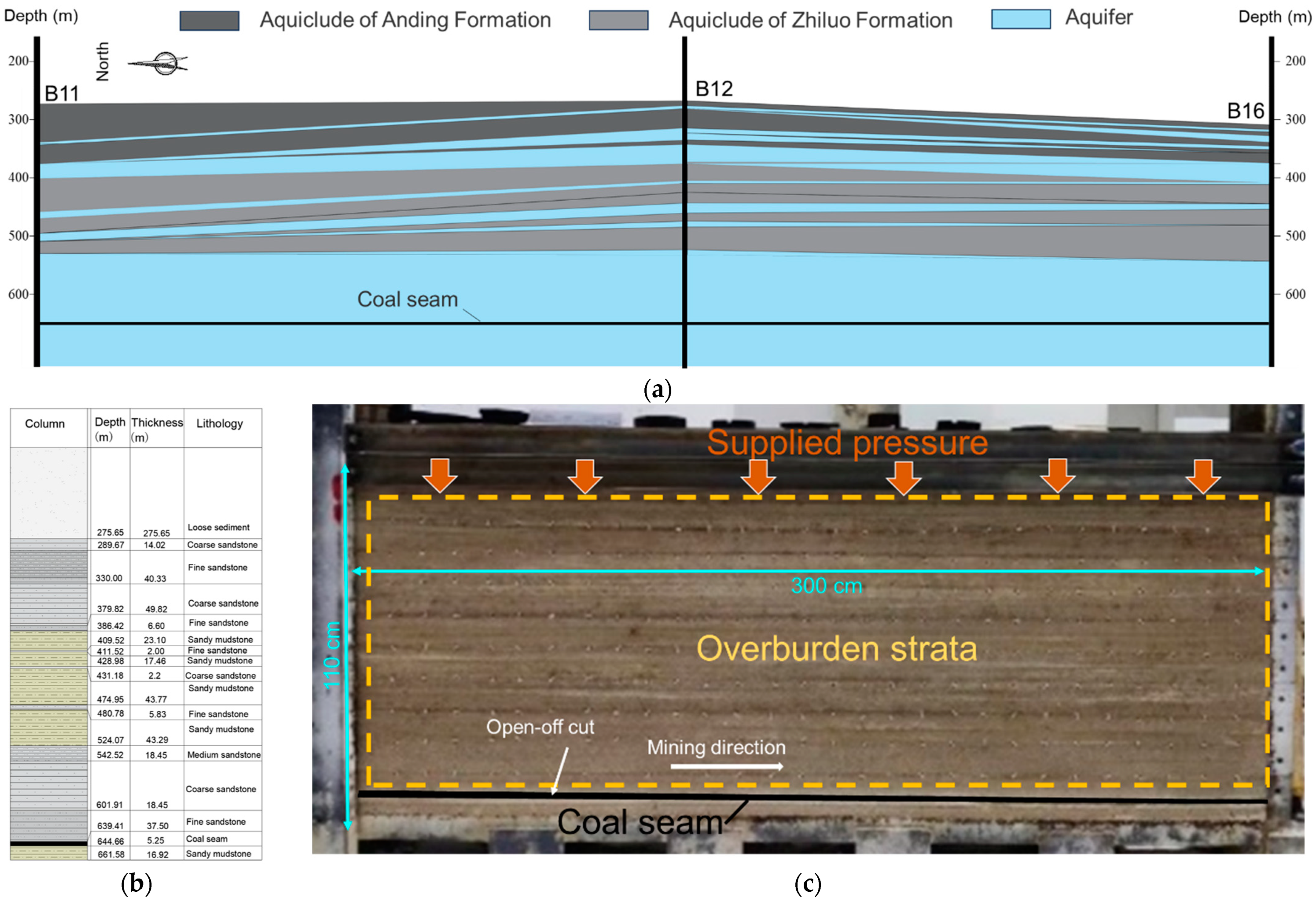
2.2.1. Scale Model Establishment
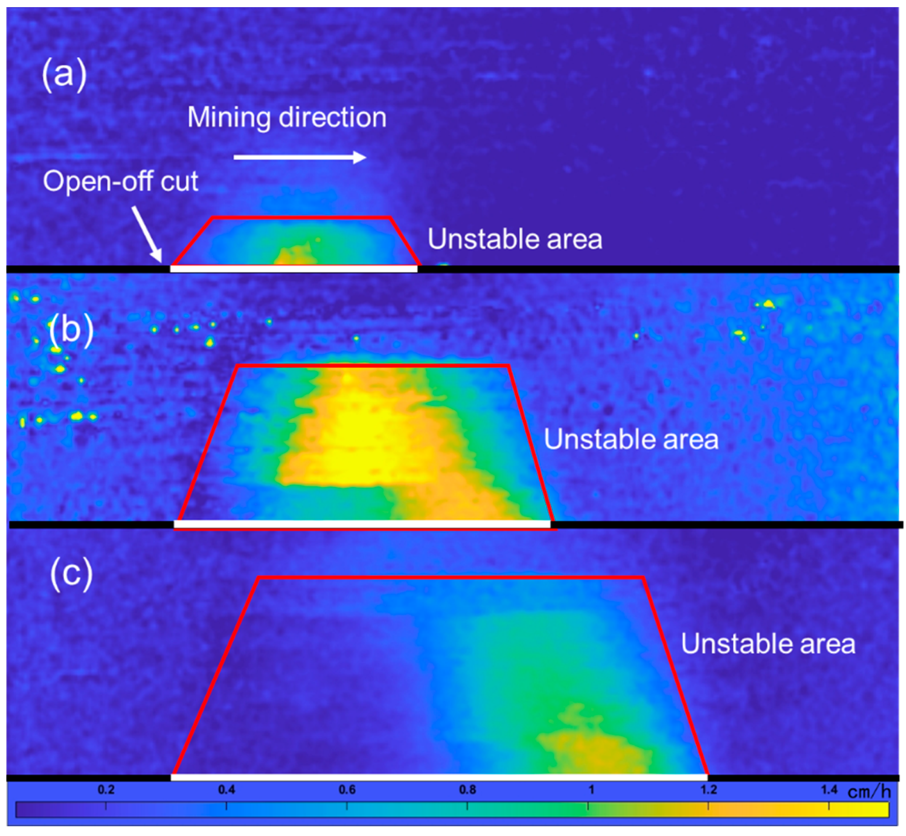
Due to the large burial depth, a similarity model with a geometric similarity ratio of 1:500 was established in the laboratory to simulate the development and evolution process of the separation layer during the mining of the Muduchaideng coal mine.
To achieve similarities between the experimental phenomena and actual on-site phenomena, three conditions must be met: geometric similarity, dynamic similarity, and motion similarity [30]. The similarity ratio, calculated according to experimental requirements, is shown in Table 2.
The elevation of the coal seam with a thickness of 5.25 m varies from −639 m to −644 m. The size of the model is 300 cm × 30 cm × 119 cm, with a distribution load of 216 kN applied on the top of the scale model to simulate the gravitational pressure of the soil layers, which was calculated by the following formula:
q m = γ ( H H m ) C γ C l l b
where q m is the applied distribution load; H is the buried depth of the coal seam; H m is the height of the overlying strata in the scale model; γ is the average unit weight of the overlying strata; l is the length of the model; b is the width of the scale model; C γ and C l are the similarity ratios for the unit weight and geometry of the model
As the strata is relatively flat in the study area (Figure 4a), an experimental model (Figure 4c) was simplified based on the stratum in borehole TC 1. Moreover, the scale model was free in the vertical direction on both side boundaries and fixed in the bottom and horizontal directions, which provide a lateral restraint.

2.2.2. PIV

As the geometric similarity ratio used in this article is 1:500, the displacement of overburden strata is very small when reflected in the experiment model. In order to capture such small changes, this study combined PIV technology to process the displacement images of the overlying strata to analyze the displacement and deformation characteristics that occur during mining. The PIV method is mainly used to determine the transient displacement of the flow field by comparing sequential photographs [31]. In geotechnical laboratory tests, the PIV method has also recently been used by some researchers in geotechnical mechanics for the displacement analysis of materials subjected to deformation as loading progresses [32,33,34]. A two-dimensional PIV system was used in this study. Through analyzing the distribution of the velocity and strain band during mining, the deformation of the overlaying stratum can be studied.

2.3. Field Measurement

Two boreholes were completed in the field construction: borehole TC1 and borehole TC2 (Figure 3). The construction lasted from 27 May 2020 to 17 October 2020. The figure shows the on-site drilling work.
During the implementation of the project, the 30202 panel was used for mining. In order to detect the maximum height of the water-flowing fracture zone and the mining-induced overburden separation, TC1 was arranged in the middle of the 30202 panel. Borehole TC2 was located at least 97 m behind the 30202 panel, close to the maximum subsidence area expected after mining the 30202 panel. The depth of TC1 was 620.66 m and the depth of TC2 was 583.31 m.
Tc1 was mainly used as a reference hole to take original rock samples of the formation and send samples for testing, so as to provide basic data for subsequent exploration and research work.
The purpose of TC2 is not only to detect the height and development of the water-flowing fracture zone, but also to detect the horizon, number of layers and distribution characteristics of the separation layer.
Mud slurry consumption, water level observation and downhole TV were determined for each hole. The downhole TV method utilizes an underground color TV system consisting of an underground camera, system controller, dedicated cable, automatic winch, color monitor, and recorder to observe the interior of the borehole. This enables the direct observation of cracks, voids, weak interlayers, and other conditions inside the borehole on the color monitor on the surface, and the data can be saved on recorded discs for further reference.

3. Results and Analysis

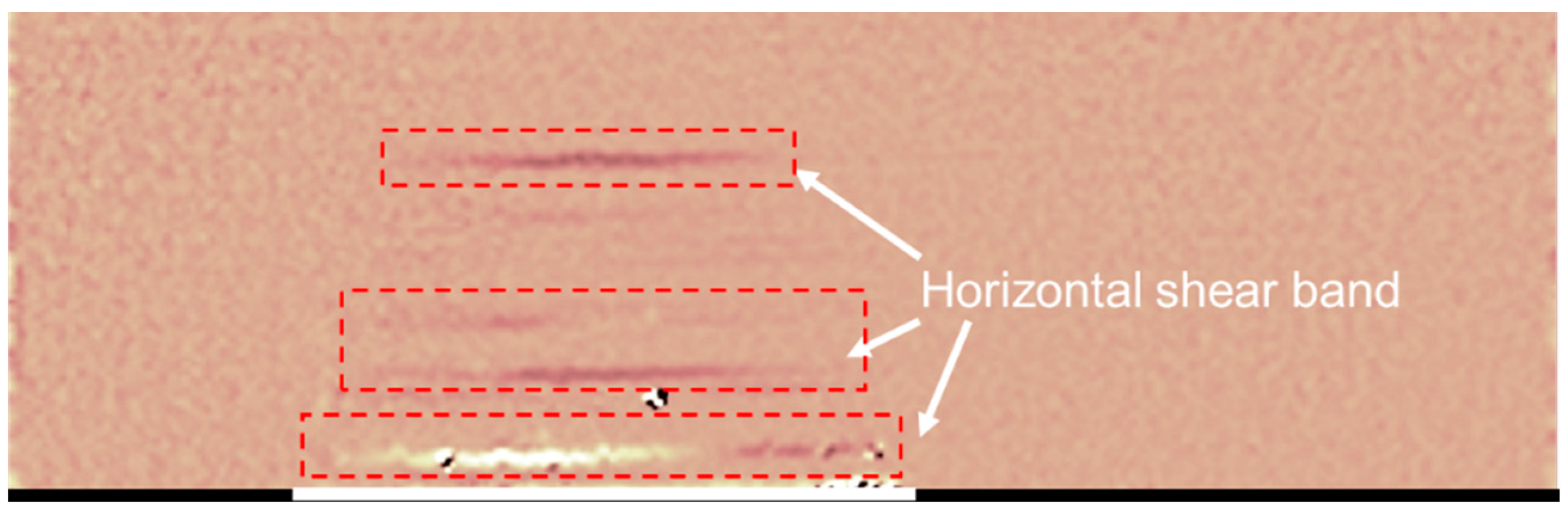
3.1. Development Characteristics of Separation Layer

In the real-time monitoring of the excavation process, the velocity field cloud image presented a trapezoidal shape, wherein the area moved downwards, indicating an unstable area. The stratum above the unstable area remained in a stable state. The trapezoidal-shaped unstable area continued to develop forward with advances in excavation. At the same time, as the unstable area collapsed, stratum above the unstable area lost support and also trended to move downwards, and the trapezoidal unstable area further developed upwards.
Figure 5 shows the evolution of the velocity field cloud image of the damage to the overlying strata during the excavation of the coal seam. When there is no excavation, the strata remain stable. When the excavation reached 70 cm, the height of the unstable area is approximately 25 cm, corresponding to an actual formation height of 125 m. As excavation continues, the unstable area further develops upwards. When the excavation reaches 120 cm, the height of the unstable area reaches 56 cm, corresponding to an actual formation height of 280 m. With continued mining, when the excavation spacing reaches 160 cm, the height of the unstable area reaches 70 cm, corresponding to an actual formation height of 350 m.
After further extracting the shear zones of the strata during the excavation process, it was found that the shear band mainly extended horizontally and was distributed below the unstable area. Figure 6 showed the distribution of shear zones with an excavation width of 100 cm.
Based on the trapezoidal instability area that occurs during these deeply buried excavations, the upper edge of the trapezoid is far beyond the influence range of the cave zone and fracture zone, and can be regarded as the development position of the separation layer.
Therefore, it was thought that the horizontal shear zones were mainly concentrated in the depths of 289.67–322.48 m, 386.42–431.18 m, and 474.95–524.07 m.

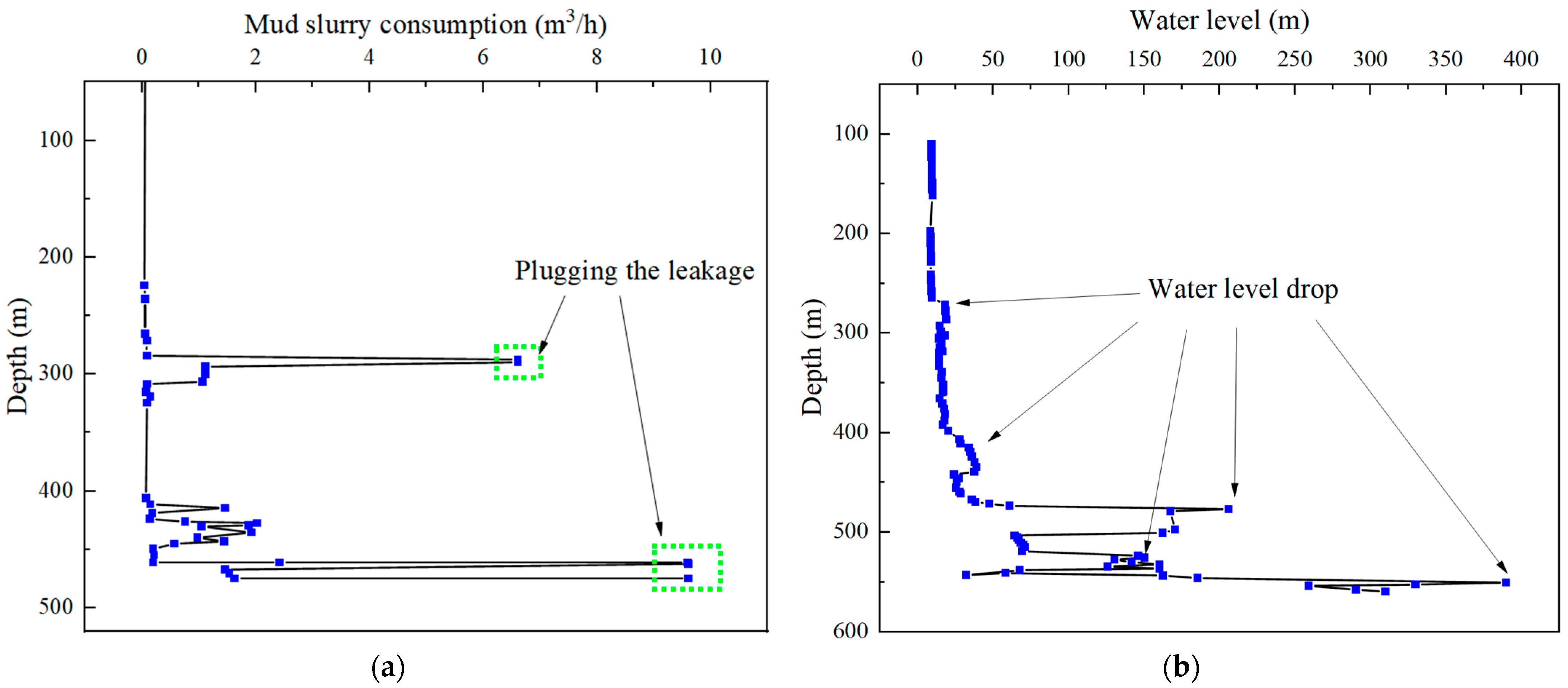
3.2. Mud Slurry Consumption and Water Level during Drilling

Figure 7a showed the variation in mud slurry consumption with depth during the drilling process. The normal mud consumption during drilling is between 0.02 to 0.04 m3/h, and a consumption greater than 1 m3/h was considered abnormal. When drilling to a depth of 286.64 to 290.55 m, the mud slurry began to leak, with a loss of 6.6 m3/h. After plugging the leak, normal drilling resumed. When drilling to a depth of 415.19 m, the leakage suddenly increased from 0.12 m3/h to 1.44 m3/h. As the drilling continued to a depth of from 422 to 464.91 m, the leak gradually increased, with a total pump loss of 9.6 m3/h, ranging from 461.97 to 464.91 m. After plugging the leakage point again, the drilling continued. From 465 m to 473 m, the leak gradually increased, and at 474 m, it started to leak completely. From 474 m to 536.70 m, various materials, such as sawdust, a high-efficiency sealing agent, limestone powder, and plant glue, were used to plug the leakage. Therefore, it can be inferred that the locations where the crack area occurred were around 286 to 304 m, 415 to 434 m, 461 to 474 m, and there was also a serious collapse area that developed below 474 m due to the complete mud slurry loss.
Figure 7b showed the water level observations. The water level decreased at depths of from 264.78 to 271.13 m and 398.49 to 406.89 m. At a depth of from 473.79 to 477.12 m, the water level suddenly dropped from 61 m to 285.40 m (a complete leak occurred at a depth of 474 m, and plugging was carried out). At depths of from 519.44 to 536.70 m, the water level decreased from 69.50 m to 146.90 to 160.30 m. Plugging drilling was conducted from a depth of 474 m to 536.70 m. At depths of from 546.26 to 551.00 m, the water level suddenly dropped from 185.40 m to 389.40 m. The decrease in water level indicated significant formation leakage and fractures developed at that location.
According to the comprehensive analysis of mud consumption and water level changes in borehole TC2, the separation layers are mainly concentrated in the segments of from 271.23 to 304.66 m, 398.49 to 434 m, and 461 to 477 m, which is consistent with the results of indoor experiments.

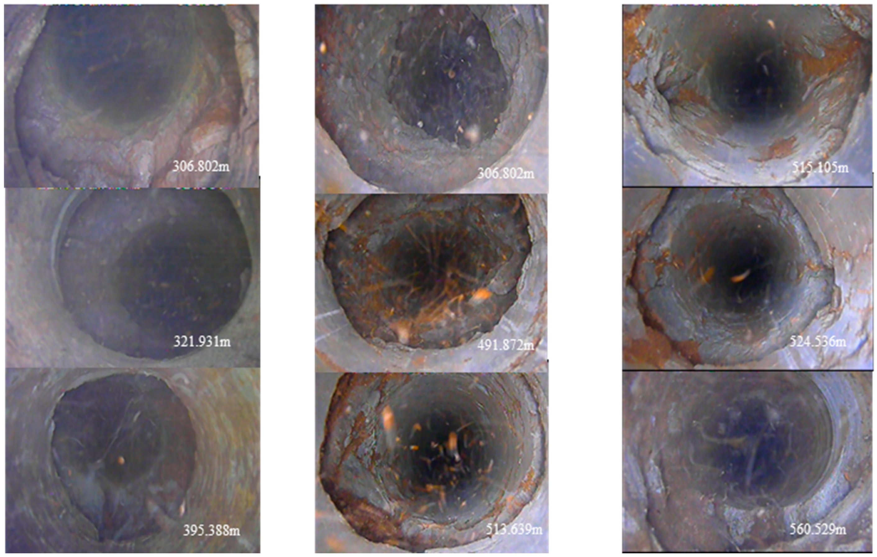
3.3. Borehole Damage at the Locations of Laminated Fracture Development Layers

Based on the model experiments and drilling results, we conducted downhole television observations of fracture development in the target layers. On 29 August 2020, the first downhole television survey was conducted in the TC2 borehole, revealing the presence of laminated fractures in 11 locations, mainly concentrated between 302–322 m and 395.5–433 m. The downhole television images showed significant development of transverse fractures at multiple depths, including 307 m, 321 m, 328 m, and 395 m. At 395 m, longitudinal and oblique fractures started to appear, while the number and width of fractures increased. Between 436 and 460 m, longitudinal fractures developed, along with a few oblique fractures. On 19 September 2020, the second downhole television logging was carried out in the depth range of 411–583 m. This revealed the presence of 21 horizontal laminated fractures and detachments, concentrated mainly between 419 and 426 m, 473 and 495.5 m, 513.6 and 524.7 m, and 534 and 548 m. Between 513 and 583 m, longitudinal, transverse, and oblique fractures developed in an irregular and chaotic manner, while the number and width of fractures continuously increased. Figure 8 depicts the state of borehole wall damage at the locations with laminated fracture development.
According to the verification from the two downhole television surveys, the more developed layers with laminated fractures and detachments were found at the depth of 302–322 m, 395–433 m, 473–495.5 m, 513.6–524.7 m, and 534–548 m. These findings are consistent with the model experiments and drilling results, and different forms of damage were observed in the borehole walls at the locations of laminated fracture development.

4. Discussion

In order to determine the mechanism of grout ground leakage in Muduchaideng coal mine, and the position of the grout layer, borehole wall deformation was discussed, combining the results from experiments and on-site observation.

4.1. Separation Layer Grout Position Selection

Principle of grouting layer selection:
(1) The grouting layer is located above the water-flowing fracture zone;
(2) The grouting layer should avoid the underground drinking-water source;
During grouting, in order to prevent the separation zone from penetrating the water flowing fracture zone, a maintenance zone of about five times the mining height of the coal seam should be reserved, with a thickness of 5 × 4.9 = 24.5 m, and the layer of separation grouting should be more than 157.5 m away from the coal seam. Furthermore, the separation layers at the 513.6~524.7 m and 534~548 m obviously developed longitudinal fissures. Therefore, this position cannot be used as the grouting layer.
The separation layer located around 300 m depth is in the lower part of the Zhidan group, which has good water abundance and is the drinking water source for residents. Grouting in this layer easily pollutes the drinking water source and this layer is also not suitable for grouting.
Separation layers developed at 400 m depth are located in the upper part of the Zhiluo formation, which is separated from the drinking water source of Zhidan group by good aquifuge. Grouting in the separation zone will not pollute the groundwater. There are also multi-layer aquifuges between the water flowing fracture zone. Grouting in these layers also does not pose a threat to the underground. Therefore, the grouting layer is at this position was selected.

4.2. Impact of Mining on Borehole Integrity

From the experimental results and the observation from surrounding drilling, it was obvious that the disturbances caused by mining were located above the grout position. On 27 September 2020, the panel was just below the TC 1 borehole, and the first downhole television logging was conducted in the TC 1 borehole (depth range: 289.6–452 m). On 3 October, as the panel advanced beyond the mining front by 33 m, the second downhole television logging was carried out. However, severe horizontal displacement at 393 m caused a reduction in the borehole diameter, making it impossible to insert the instruments, leading to termination of the logging.
Both downhole television images demonstrated that the borehole walls were relatively intact. However, compared to the first logging, the deformation of the strata was more significant during the second logging, due to mining. Figure 9 showed the deformation of the borehole wall at the depth of 393 m during the first and second logging in the TC1 borehole. In addition, it can also be clearly observed that there were some other forms of damage to drilling holes when conducting an underground television exploration. The damage forms included the following: cracks, dislocation, separation, collapse, block falling, and hole shrinkage. Furthermore, the borehole damage will further lead to the destruction of grouting pipelines. According to on-site statistics, there were three main forms of pipeline failure, which correspond to the borehole failure (Table 3).

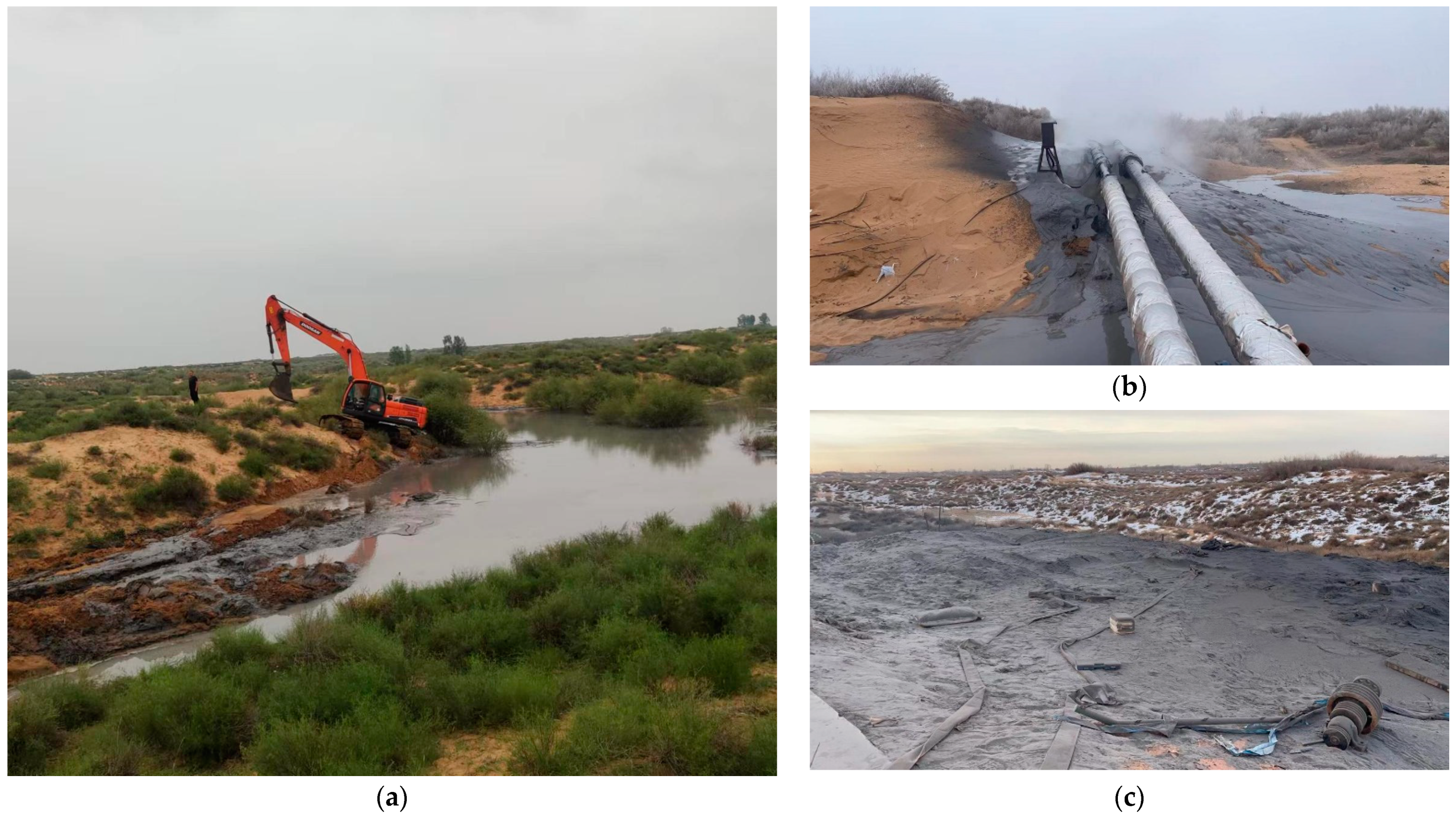
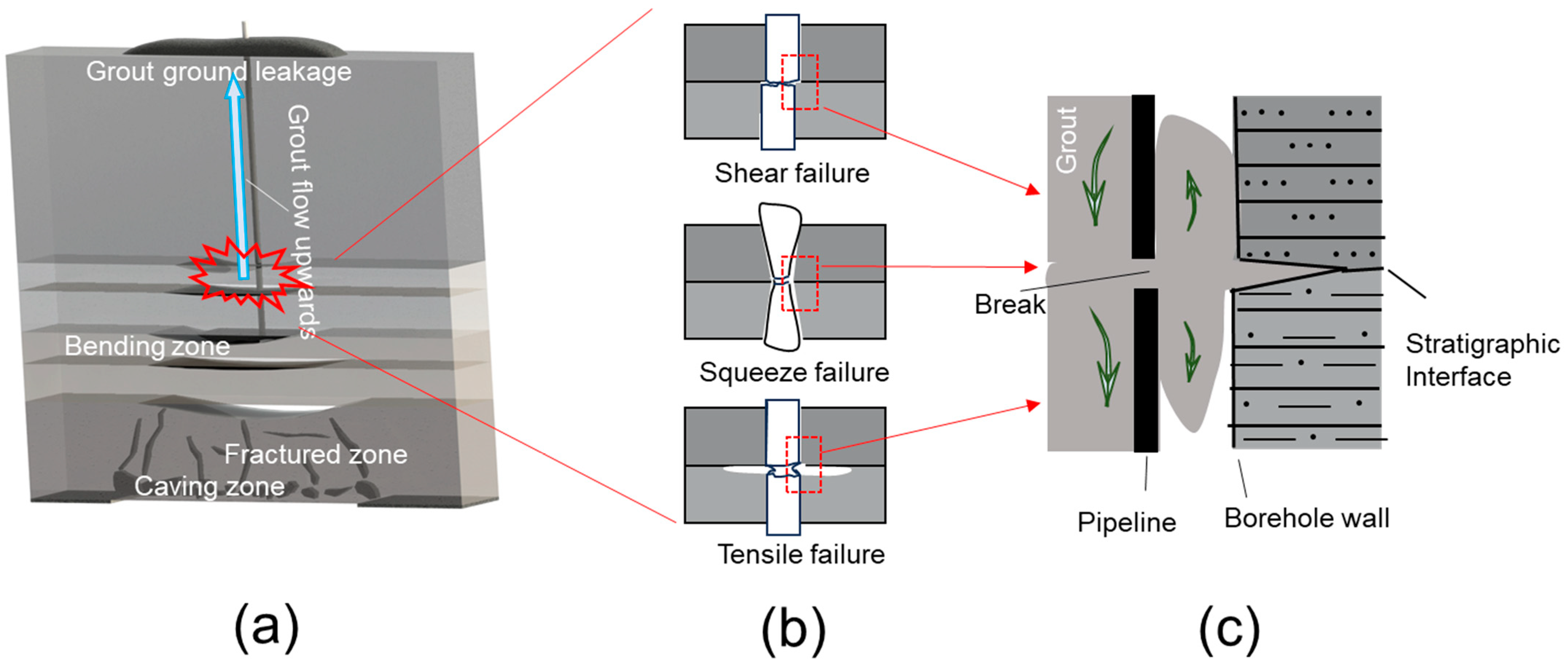
4.3. Mechanism of the Grout Ground Leakage in Muduchaideng Coal Mine

In the Muduchaideng coal mine separation layer grout project, the grout pipeline was seriously destroyed. As the coal seam continues to be excavated, the overlying strata become unstable, resulting in collapse, fracture, and separation layers. The strata above the separation layer lose support, moving downward. The development height of the separation layer increases with the panel’s advancement [26,27].
Injecting grout into the separation layer can prevent the overlying strata from continuing to subside, but once the grouting efficiency is not ideal, the overlying strata will continue to collapse, and the separation layer will continue to develop upwards. In the area where the separation layer developed, the borehole is destroyed, as well as the inside grout pipeline. The grout will leak from the break point of the pipeline. Then, the leaked grout will backflow along the borehole walls to the ground surface, resulting in ground grout leakage, as shown in Figure 10.

5. Conclusions

  • This study revealed the mechanism of grout ground leakage caused by the development of separation layers during mining in a case study of Muduchaideng coal mine. The conclusions are as follows:
  • Through laboratory experiments and field drilling verification, the position of the separation layer at the Muduchaideng coal mine was validated at the depths of 289.67–322.48 m, 386.42–431.18 m, and 474.95–524.07 m. These positions are above the grout layer and the borehole wall was seriously disturbed.
  • A mechanism of grout ground leakage was proposed. The position of the separation layer develops upwards due to poor settlement control. The development of separation will result in borehole integrity damage, which will further lead to breaks in the grout pipeline. Then, the grout will backflow along the borehole walls to the surface, eventually resulting in surface slurry leakage.
  • This study has implications for providing a warning to prevent grout ground leakage.

Author Contributions

Conceptualization, B.X., W.S. and X.M.; methodology, B.X. and X.M.; validation, W.S.; formal analysis, B.X., W.S. and X.M.; investigation, B.X. and X.M.; resources, B.X. and X.M.; data curation, B.X. and X.M.; writing—original draft preparation, B.X., W.S. and X.M.; writing—review and editing, W.S., X.M., S.Y. and Y.H.; visualization, X.M.; supervision, W.S.; project administration, W.S. All authors have read and agreed to the published version of the manuscript.

Funding

This research was funded by the National Key R&D Program of China (Grant No. 2023YFC3012103).

Data Availability Statement

Data are contained within the article.

Conflicts of Interest

The authors declare no conflicts of interest.

References

  1. Cheng, G.W.; Ma, T.H.; Tang, C.N.; Liu, H.Y.; Wang, S.J. A zoning model for coal mining-induced strata movement based on microseismic monitoring. Int. J. Rock. Mech. Min. Sci. 2017, 94, 123–138. [Google Scholar] [CrossRef]
  2. Chen, L.W.; Feng, X.Q.; Xie, W.P.; Xu, D.Q. Prediction of water-inrush risk areas in process of mining under the unconsolidated and confined aquifer: A case stud from the Qidong coal mine in China. Environ. Earth Sci. 2016, 75, 706. [Google Scholar] [CrossRef]
  3. He, J.H.; Li, W.P.; Fan, K.; Qiao, W.; Wang, Q.; Li, L. A method for predicting the water-flowing fractured zone height based on an improved key stratum theory. Int. J. Min. Sci. Technol. 2023, 33, 61–71. [Google Scholar] [CrossRef]
  4. He, J.H.; Li, W.P.; Liu, Y.; Yang, Z.; Liu, S.L.; Li, L.F. An improved method for determining the position of overlying separated strata in mining. Eng. Fail. Anal. 2018, 83, 17–29. [Google Scholar] [CrossRef]
  5. Majdi, A.; Hassani, F.P.; Nasiri, M.Y. Prediction of the height of destressed zone above the mined panel roof in longwall coal mining. Int. J. Coal Geol. 2012, 98, 62–72. [Google Scholar] [CrossRef]
  6. Das, S.K. Observations and classification of roof strata behaviour over longwall coal mining panels in India. Int. J. Rock. Mech. Min. Sci. 2000, 37, 585–597. [Google Scholar] [CrossRef]
  7. Meng, Z.P.; Shi, X.C.; Li, G.Q. Deformation, failure and permeability of coal-bearing strata during longwall mining. Eng. Geol. 2016, 208, 69–80. [Google Scholar] [CrossRef]
  8. Mark, C.; Molinda, G.M. Coal mine roof rating: A decade of experience. Int. J. Coal Geol. 2005, 64, 85–103. [Google Scholar] [CrossRef]
  9. Xuan, D.; Xu, J.; Wang, B. Borehole Investigation of the Effectiveness of Grout Injection Technology on Coal Mine Subsidence Control. Rock. Mech. Rock. Eng. 2015, 48, 2435–2445. [Google Scholar] [CrossRef]
  10. Xu, J.; Xuan, D. Cost Investigation of the Coalmine Subsidence Control Technology of Isolated Overburden Grout Injection. Geotech. Geol. Eng. 2019, 37, 4251–4258. [Google Scholar] [CrossRef]
  11. Wang, B.; Xu, J.; Xuan, D. Time function model of dynamic surface subsidence assessment of grout-injected overburden of a coal mine. Int. J. Rock. Mech. Min. Sci. 2018, 104, 1–8. [Google Scholar] [CrossRef]
  12. Zou, L.; Håkansson, U.; Cvetkovic, V. Analysis of Bingham fluid radial flow in smooth fractures. J. Rock. Mech. Geotech. 2020, 12, 1112–1118. [Google Scholar] [CrossRef]
  13. Xuan, D.; Li, J.; Zheng, K. Experimental Study of Slurry Flow in Mining-Induced Fractures during Longwall Overburden Grout Injection. Geofluids 2020, 2020, 8877616. [Google Scholar] [CrossRef]
  14. Jin, L.; Sui, W. Experimental investigation on chemical grouting in rough 2D fracture network with flowing water. Bull. Eng. Geol. Environ. 2021, 80, 8519–8533. [Google Scholar] [CrossRef]
  15. Sui, W. Experimental investigation on sealing efficiency of chemical grouting in rock fracture with flowing water. Tunn. Undergr. Space Technol. 2015, 50, 239–249. [Google Scholar] [CrossRef]
  16. Jin, L.; Sui, W. Experimental Investigation on Chemical Grouting in a Permeated Fracture Replica with Different Roughness. Appl. Sci. 2019, 9, 2762. [Google Scholar] [CrossRef]
  17. He, S.; Lai, J.; Wang, L.; Wang, K. A literature review on properties and applications of grouts for shield tunnel. Constr. Build. Mater. 2020, 239, 117782. [Google Scholar] [CrossRef]
  18. Jiang, C.; Wang, Y.; Duan, M.; Guo, X.; Chen, Y.; Yang, Y. Experimental study on the evolution of pore-fracture structures and mechanism of permeability enhancement in coal under cyclic thermal shock. Fuel 2021, 304, 121455. [Google Scholar] [CrossRef]
  19. Jin, Y.; Han, L.; Xu, C.; Meng, Q.; Zong, Y. Cement Grout Nonlinear Flow Behavior through the Rough-Walled Fractures: An Experimental Study. Geofluids 2020, 2020, 9514691. [Google Scholar] [CrossRef]
  20. Zhang, G.L. Mechanism of deflection propagation for grouting in fractured rock mass with flowing water and mining effect on grouted curtain: A review. J. Eng. Geol. 2022, 30, 987–997, (In Chinese, Abstract in English). [Google Scholar]
  21. Jiang, X.; Zheng, G.; Sui, W. Anisotropic propagation of chemical grouting in fracture network with flowing water. ACS Omega 2021, 6, 4672–4679. [Google Scholar] [CrossRef]
  22. Zheng, G.; Sui, W.; Zhang, G. Propagation and sealing efficiency of chemical grouting in a two-dimensional fracture network with flowing water. Int. J. Min. Sci. Technol. 2023, 33, 903–917. [Google Scholar] [CrossRef]
  23. Wang, Y.; Yang, P.; Li, Z.; Wu, S.; Zhao, Z. Experimental-numerical investigation on grout diffusion and washout in rough rock fractures under flowing water. Comput. Geotech. 2020, 126, 103717. [Google Scholar] [CrossRef]
  24. Yan, C.; Tong, Y.; Luo, Z.; Ke, W.; Wang, G. A two-dimensional grouting model considering hydromechanical coupling and fracturing for fractured rock mass. Eng. Anal. Bound. Elem. 2021, 133, 385–397. [Google Scholar] [CrossRef]
  25. Kou, T.; Wen, S.; Mu, W.; Xu, N.; Gao, Z.; Lin, Z.; Liu, H. Slurry leakage channel detection and slurry transport process simulation for overburden bed separation grouting project: A case study from the wuyang coal mine, northern China. Water 2023, 15, 996. [Google Scholar] [CrossRef]
  26. Zhang, Z.J. Overburden abscission layer spatial-temporal evolution pattern and grouting mining practice—A case study of 3117 working face in Xiadian coal mine. Coal Geol. China 2023, 35, 33–40, (In Chinese, Abstract in English). [Google Scholar]
  27. Xu, L.J.; Zhang, K.; Liu, X.P. Deformation characteristic of key strata and control effect of surface subsidence in mining with grouting into overburden bed-separation. J. China Coal Soc. 2023, 48, 931–942, (In Chinese, Abstract in English). [Google Scholar]
  28. Wang, K. Development status of technology studies of grouting into overburden bed-separation of coal mine in China. Coal Technol. 2016, 35, 42–44, (In Chinese, Abstract in English). [Google Scholar]
  29. Yao, W.T.; Kou, T.H.; Fan, B. Influence evaluation of mining-induced strata separation grouting on mine safety. Coal Technol. 2022, 41, 170–174, (In Chinese, Abstract in English). [Google Scholar]
  30. Liu, J.; Sui, W.; Zhao, Q. Environmentally sustainable mining: A case study of intermittent cut-and-fill mining under sand aquifers. Environ. Earth Sci. 2017, 76, 562. [Google Scholar] [CrossRef]
  31. White, D.J.; Take, W.A.; Bolton, M.D. Soil deformation measurement using particle image velocimetry (PIV) and photogrammetry. Geotechnique 2003, 53, 619–631. [Google Scholar] [CrossRef]
  32. Bi, Z.Q.; Gong, Q.M.; Guo, P.J.; Chen, Q. Experimental study of the evolution of soil arching effect under cyclic loading based on trapdoor test and particle image velocimetry. Can. Geotech. J. 2020, 57, 903–920. [Google Scholar] [CrossRef]
  33. Khatami, H.; Deng, A.; Jaksa, M. The arching effect in rubber–sand mixtures. Geosynth. Int. 2020, 4, 432–450. [Google Scholar] [CrossRef]
  34. Zhao, Y.; Gong, Q.M.; Wu, Y.J.; Tian, Z.Y.; Zhou, S.H.; Fu, L.L. Progressive failure mechanism in granular materials subjected to an alternant active and passive trapdoor. Transp. Geotech. 2021, 28, 100529. [Google Scholar] [CrossRef]
Figure 1. (a) River filling caused by grout ground leakage. (b) Grout flow back in borehole. (c) Grout spread on the ground surface.
Water 16 00211 g001
Figure 2. Location of the study area.
Water 16 00211 g002
Figure 3. Layout of the panel and boreholes.
Water 16 00211 g003
Figure 4. (a) Geological profile; (b) stratum column in borehole TC 1; (c) experimental model.
Water 16 00211 g004
Figure 5. Velocity field of the overlaying stratum when mining (a) 70 cm, (b) 120 cm, (c) 160 cm.
Water 16 00211 g005
Figure 6. Position of the horizontal shear band when mining 100 cm.
Water 16 00211 g006
Figure 7. (a) Mud slurry consumption during drilling and (b) water level observations in TC2 borehole.
Water 16 00211 g007
Figure 8. Borehole conditions at the location of separation layers.
Water 16 00211 g008
Figure 9. Underground television of TC 1 borehole at 393 m (a) before mining and (b) after mining.
Water 16 00211 g009
Figure 10. (a) Mechanism of grout ground leakage. (b) Grout pipeline failure pattern. (c) Grout leakage in the pipeline break point.
Water 16 00211 g010
Table 1. Adaptation conditions for the development of separation strata in Muduchaideng coal mine.
FactorsAdaptation ConditionsMuduchaideng Coal Mine Conditions
Strata structureInterbedsInterbedding of sandstone, sandy mudstone and mudstone
LithologyLarge difference in hardnessLarge difference in hardness
Geological structureNo faultNo fault
Mining methodFully mechanized mining and complete collapse in longwall panelFully mechanized mining and complete collapse in longwall panel
Coal seam occurrenceHorizontal or gently inclined coal seamAngle 1–3°
Table 2. Similarity ratio of the model.
Geometry RatioDensity RatioStrength RatioTime Ratio
1:5001:1.671:8351:22.36
Table 3. Pipeline failure pattern.
Failure Type of the PipelineCause
Shear failureStrata slide along the interface, pipeline is subjected to radial force, resulting in shear failure
Squeeze failureThe pipeline yields and deforms under the pressure of the formation.
Tensile failureSeparation layer develops and the pipeline is stretched; obvious tensile deformation occurs at this position.
Disclaimer/Publisher’s Note: The statements, opinions and data contained in all publications are solely those of the individual author(s) and contributor(s) and not of MDPI and/or the editor(s). MDPI and/or the editor(s) disclaim responsibility for any injury to people or property resulting from any ideas, methods, instructions or products referred to in the content.

