Article

Steady-State Shape Factor for a Slug Test in an Unconfined Aquifer

by
Florimond De Smedt
Department of Water and Climate, Vrije Universiteit Brussel, Pleinlaan 2, 1050 Brussels, Belgium
Water 2024, 16(19), 2853; https://doi.org/10.3390/w16192853
Submission received: 2 August 2024 / Revised: 21 September 2024 / Accepted: 1 October 2024 / Published: 8 October 2024

Abstract

:
A new solution is presented for the steady-state shape factor of a partially penetrating well in an unconfined aquifer. The problem is solved by taking into account mixed boundary conditions at the well, i.e., zero flux at the well casing and constant head at the well screen equal to the head in the well so that the flow through the well screen is non-uniform. The new method is compared with established methods, such as those of Bouwer and Rice and Zlotnik et al., demonstrating that the new approach provides more accurate results under certain conditions. The comparison highlights that the new method is particularly effective in scenarios where the assumptions of uniform flow through the well screen do not hold. This study assumes idealized conditions, such as homogeneity, isotropy, and negligible storativity in the aquifer, which may limit the method’s applicability in more complex environments. The computational demands of the iterative solution process may pose challenges for practical use, especially in resource-constrained settings.

1. Introduction

The slug test is a simple method to estimate the hydraulic conductivity of a water-bearing formation by measuring the recovery of head (water level) in a well after an instantaneous removal or injection of a small amount of water [1]. There are two approaches for analyzing a slug test, depending on whether aquifer storage is taken into account. The traditional way is to ignore aquifer storage [2,3,4,5] so that groundwater flow can be considered as a quasi-steady-state, which largely simplifies the analysis, while the other way [6] is more complicated and less applied in practice. In this study, the classical approach is followed because a slug test usually causes only a small amount of groundwater flow, and the contrast between the changes in water storage in the well and in the soil is so large that the latter can be ignored.
Hvorslev [2] and Bouwer and Rice [3] have shown that when changes in water storage in the aquifer are negligible, the difference in head in the well varies exponentially with time, as
H = H 0 e x p 2 K L t r c 2 l o g R e / r w ,
where H [L] is the head change in the well at time t [T] since the start of the test, H 0 is the initial change in head in the well at time zero, L [L] is the length of the well screen, K [LT–1] is the hydraulic conductivity of the soil, r c [L] is the inner radius of the well casing where the changes in head are observed, R e [L] is the effective radius of the slug test, r w [L] is the outer radius of the well screen or gravel pack, if present, and log is the natural logarithm. Recordings of changes in head with time can thus be used to estimate the hydraulic conductivity of the soil around the well screen. This is usually achieved by plotting the logarithm of the head change against time and calculating the slope of a straight line fit to the data, so that the hydraulic conductivity can be derived as
K = r c 2 2 L l o g R e r w d l o g H d t .
In order to apply Equation (2), the effective radius R e needs to be known. This can be estimated as the distance from the well where the head change in the soil becomes negligible; however, it is more convenient in practice to estimate l o g R e / r w , denoted as the shape factor. The shape factor is determined by the distribution of the flow around the well screen and depends on the size of the well screen and the boundary conditions of the aquifer. Exact values of shape factors are not known, but several approximations are reported in the literature, e.g., [2,3,4,5,7,8,9,10,11,12,13,14,15,16]. Discussions and reviews on the derivation of shape factors for slug tests have also been reported in the literature, e.g., [1,5,9,17,18,19,20,21], but no single approach has been proven to be conclusive.
A commonly used and very simple approach proposed by Hvorslev [2] ignores the boundary conditions of the aquifer and assumes that, for large aspect ratios of the well screen, the effective radius equals the well screen length. In practice, the method of Bouwer and Rice [3] is also widely used. This method gives empirical shape factor values for slug tests in unconfined aquifers that are obtained by interpolation of electric–analog simulations. It also takes into account the distance of the well screen to the water table and the impermeable bottom of the aquifer. Recently, Zlotnik et al. [5] presented an approximate analytical solution to the same problem by assuming that the flow through the well screen is uniform.
The purpose of this work is to present a solution for the shape factor of slug tests performed at a partially penetrating well in an unconfined aquifer with negligible storativity, assuming non-uniform flow through the well screen and taking into account the effects of aquifer boundaries. This method is shown to be superior to previous approaches.

2. Materials and Methods

The basic setup of a slug test performed at a partially penetrating well is shown in Figure 1. The aquifer is assumed to be homogeneous, isotropic, unconfined, and of uniform thickness.
The quasi-steady-state groundwater flow equation is given by
1 r r r h r + 2 h z 2 = 0 ,         r > r w ,     0 < z < b ,
where h ( r , z ) [L] is the hydraulic head in the aquifer, r [L] is the radial distance from the center of the well, z [L] is the elevation measured from the water table, and b [L] is the saturated thickness of the aquifer. Appropriate boundary conditions are
h r , 0 = 0 ,
h z r , b = 0 ,
h ( r w , d l < z d + l ) = H ,
h r r w , z < d l = h r r w , z > d + l = 0 ,
h ( r , z ) = 0 ,
where d [L] is the depth from the water table to the center of the well screen and l = L / 2 [L] is the half-length of the well screen. The main assumptions of the model are a homogeneous, isotropic aquifer with negligible storativity (Equation (3)); a fixed, constant-head boundary at the water table (Equation (4)); and mixed boundary conditions at the well (Equations (6) and (7)).
The shape factor is obtained from the linear relationship between the drawdown H in the well and the discharge Q [L3/T] to or from the well [4,5] as follows
l o g R e r w = 2 π K L H Q = H / r w 1 2 l d l d + l h r r w , z d z ,
where the expression in the denominator on the right-hand side is the average hydraulic gradient at the well screen.

3. Results

The solution is obtained by means of the finite Fourier sine transform
h r , z = n = 1 h n r   s i n ( α n z ) ,
h n ( r ) = 2 b 0 b h ( r , z )   s i n ( α n z ) d z ,
where
α n = ( n 1 2 ) π / b .
Equation (3) becomes
1 r r r h n r α n 2 h n = 0 ,
which can be solved, and at the well ( r = r w ) results in
h n = K 0 ( α n r w ) α n K 1 ( α n r w ) h n r ,
where h n and h n / r are finite Fourier sine transforms of h r w , z and h ( r w , z ) / r , and K 0 and K 1 are modified Bessel functions of the second kind of order zero and one, respectively. Inverse finite Fourier sine transform of Equation (14) gives
h r w , z = m = 1 K 0 ( α m r w ) α m K 1 ( α m r w ) h m r sin α m z .
Multiplication by 2 s i n ( α n z ) / b and integration over the well screen using Equation (6) yields
f n = m = 1 ( c n m c n + m 1 ) β m q m ,
where
f n = 4 sin α n d sin α n l α n b ,
c n = 2 cos ( n π d / b ) sin n π l / b n π ,
β n = K 0 α n r w α n r w K 1 α n r w ,
q n = r w H h n r .
Note that n in Equation (18) can be zero and that c 0 = 2 l / b .
Equation (16) forms a system of linear equations that can be solved for q n . Equation (16) can be rewritten in matrix form as
F = C Q ,
where F = f n , C = ( c n m c n + m 1 ) β m / β 1 , and Q = β 1 q n . The solution is obtained by matrix inversion using a Neumann series
Q = C 1 F = i = 0 I C i F ,
where I is the identity matrix. Note that the β m terms are scaled by β 1 so that all elements of C are smaller than one in absolute value, allowing convergence of the Neumann series.
The practical solution procedure goes as follows. From Equation (22), it follows that
Q = F + I C i = 0 I C i F = F + I C Q ,
which can be rearranged as
Q = Q + F C Q .
This enables one to obtain a solution by successive approximation as
Q i t + 1 = Q i t + E i t ,
where i t is the iteration level and E i t = F C Q i t are errors. Iteration starts with Q 0 = 0 and ends when all absolute errors become smaller than a tolerance. Because the system is infinite, calculations are truncated at a level that is large enough to ensure accurate results. Note that matrix C does not need to be fully constructed or stored because its elements are completely determined by the c n and β n coefficients.
The shape factor is then obtained from Equation (9) as
l o g R e r w = 4 β 1 l / b F · Q ,
where the expression in the denominator on the right-hand side is a dot product. Note that the shape factor depends on only three parameters: r w / b , l / b , and d / b .

4. Discussion

The solution presented here is verified by considering some case studies and field examples and by comparing the results with other methods. The shape factor is calculated with Equation (26) using a computer code in the form of a function written in FORTRAN 95, presented in Appendix A.

4.1. Case Studies

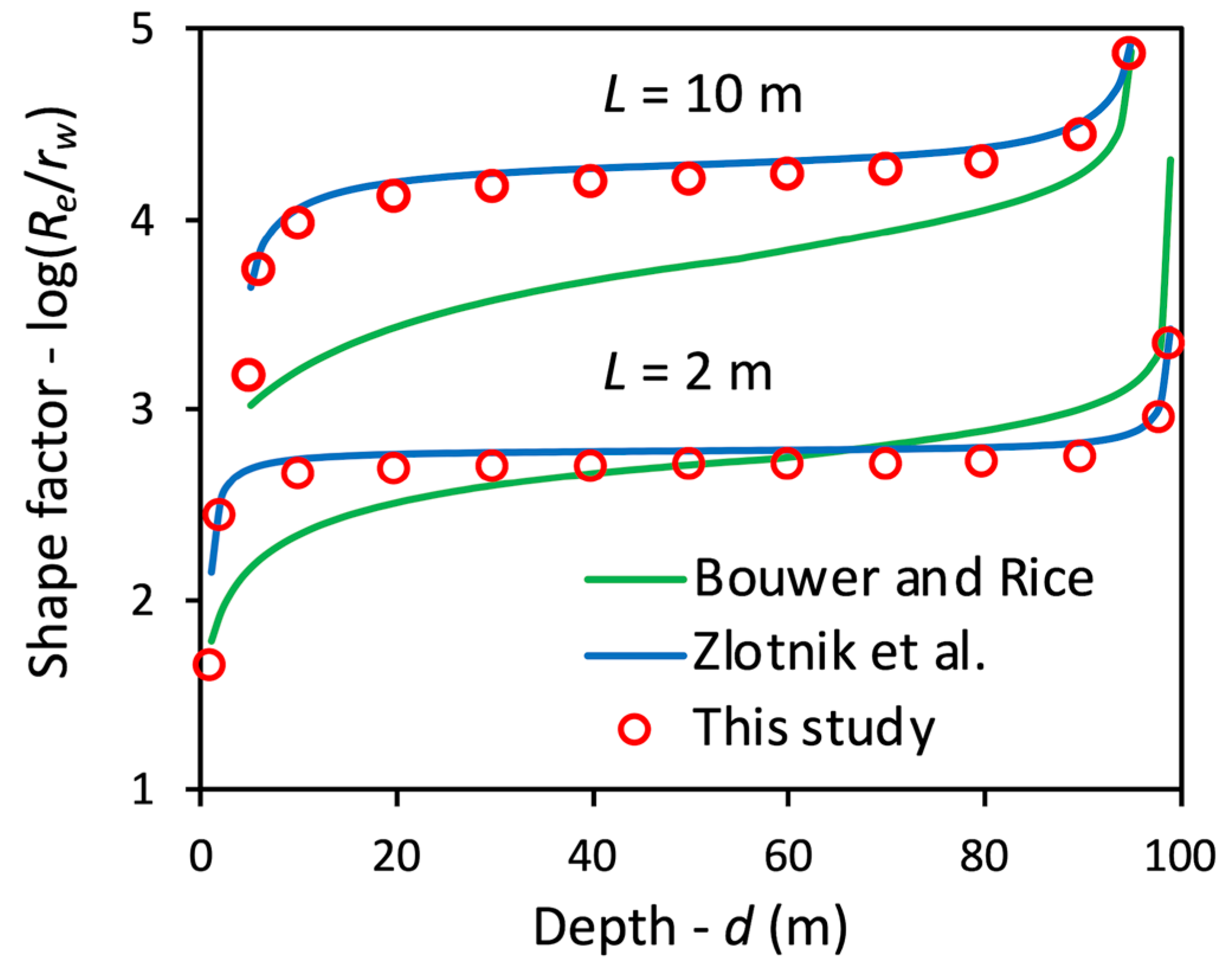
Consider an unconfined aquifer with a saturated thickness of 100 m and a partially penetrating well that has a screen with a radius of 0.1 m and a length of 2 m or 10 m that is placed at different depths in the aquifer. Figure 2 shows the shape factor obtained with the empirical approach of Bouwer and Rice [3], the approximate analytical solution of Zlotnik et al. [5], and the current solution. The first results are obtained using computer codes from Zlotnik et al. [5]. The shape factor l o g R e / r o is plotted against depth d of the well screen. The results of this study appear to be very close to Zlotnik et al.’s method, except when the screen is located at the top of the aquifer, close to the water table. Differences are approximately 3%, except at the water table where the difference is about 30%. Results obtained with the Bouwer and Rice approach clearly differ from the other methods as differences can be 20% and more. At some specific locations, such as directly below the water table, in the middle of the aquifer with the 2 m screen, or at the bottom of the aquifer with the 10 m screen, there is more agreement with the current method. A plausible explanation is that the experimental results that Bouwer and Rice obtained with the analog model were accurate but were poorly interpolated.
When the well screen is located in the middle of the aquifer, the shape factor does not vary much with depth, meaning that the aquifer boundary conditions have little influence. As such, the shape factor can be derived using the Hvorslev approach [2]. This yields shape factors of 4.61 for a screen of 10 m and 3.00 for a screen of 2 m. However, these shape factors differ by about 10% from the values of 4.21 and 2.71 obtained with the current method. This observation is consistent with De Smedt’s [16] findings that the shape factors predicted with Hvorslev’s approach are generally about 10% too large. De Smedt therefore proposed a more accurate predictor, l o g ( R e / r w ) = s i n h 1 ( L / r w ) 1 + r w / L , which in this case leads to shape factors of 4.31 and 2.74, respectively, which are close to the current results.
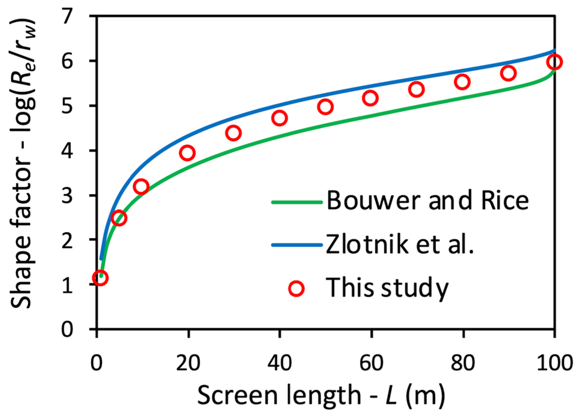
To further illustrate the differences in shape factor values for wells with screens at the water table, Figure 3 shows shape factor values for a well with a radius rw = 0.1 m and a screen length varying from 1 to 100 m. The corresponding shape factors range from 1 to 6, while the absolute differences between the current method and the methods of Bouwer and Rice and Zlotnik et al. amount to about 0.5 at most. For small screen lengths, the relative differences are thus quite large, about 20–30%, but become smaller as the screen length increases. These findings again demonstrate the influence of the water table on the groundwater flow around the well screen, and more specifically, on the non-uniformity of the flow through the well screen. Interestingly, for small screen lengths, the method of Bouwer and Rice agrees better with the current method than the method of Zlotnik et al., while for large screen lengths, Zlotnik et al.’s method is in better agreement.

4.2. Effects of Flow Distribution at the Well Screen

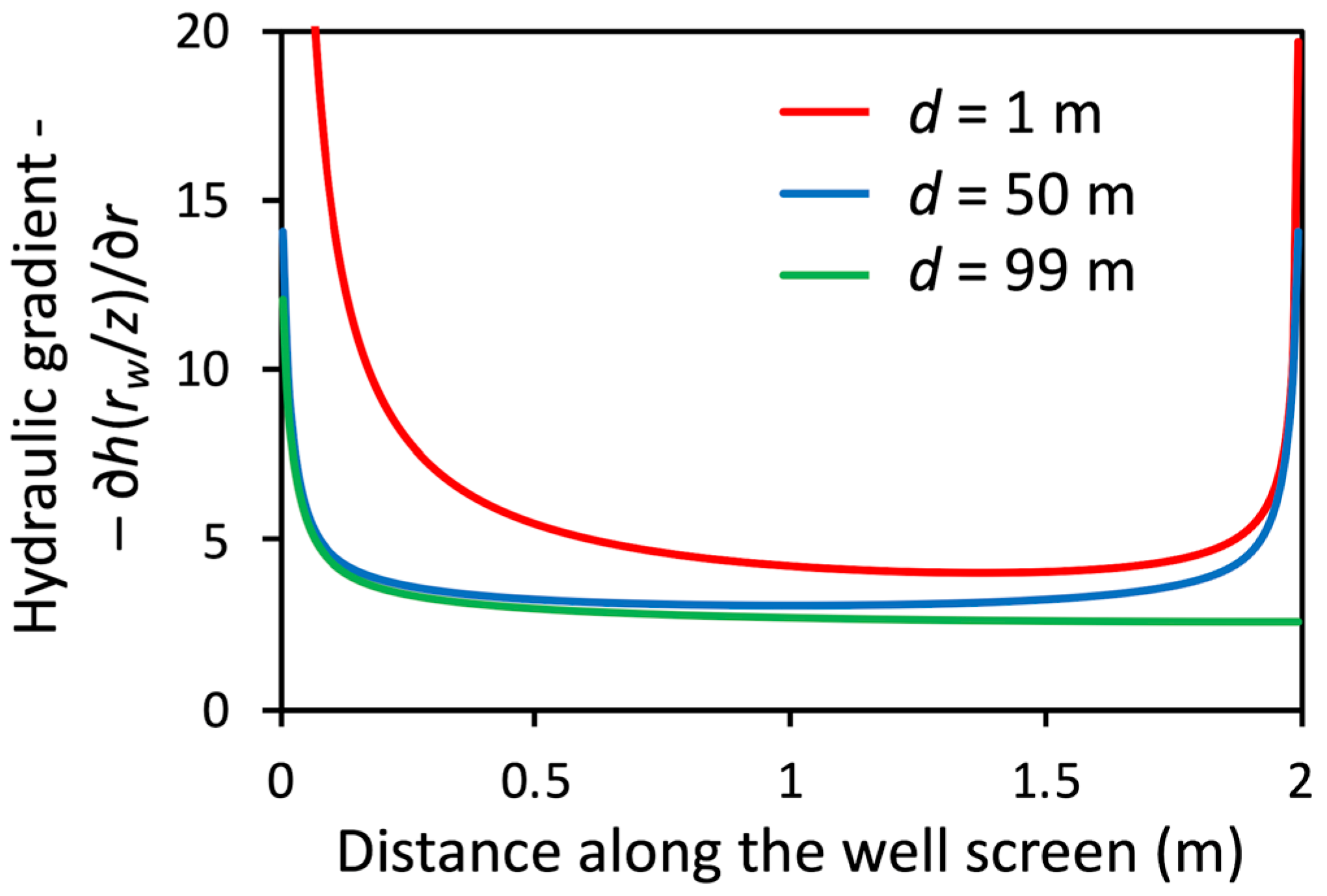
The findings discussed above indicate a possible relationship between the effects of boundary conditions and the distribution of the flow through the well screen. The distribution of the flow through the screen is determined by the hydraulic gradient h ( r w , z ) / r , which can be obtained by the inverse finite Fourier sine transform of h n / r . Figure 4 shows the profiles of the hydraulic gradient along the well screen in the case where H = 1 m and where a screen is 2 m long at depths of 1 m (just below the table), 50 m (middle of the aquifer), and 99 m (just above the impervious base), respectively. The hydraulic gradient for a well screen in the center of the aquifer is fairly uniform, except at the edges of the screen where it tends to infinity. De Smedt [16] examined slug tests not affected by boundary conditions and concluded that in such a case assuming uniform flow does not introduce much error in the derivation of the shape factor. This explains why shape factors derived in this study are very close to what is obtained with the method of Zlotnik et al. [5] in the case where the well screen is far from the aquifer boundaries. If the screen is at the bottom of the aquifer, the hydraulic gradient at the base of the aquifer does not tend to infinity, making the flow even more uniform. This case also explains why shape factors derived with the current method and with Zlotnik et al.’s method closely agree. Conversely, for a well screen at the top of the aquifer and just below the water table, the flow through the well screen becomes very asymmetric and highly non-uniform; therefore, shape factors derived with the current method and with Zlotnik et al.’s method differ significantly.
The proximity to a water table therefore has a profound influence on the shape factor, but only locally. This can be noticed in Figure 2 by the rather abrupt decrease of the shape factor values near the water table. The influence of the water table decreases rapidly and becomes negligible at a depth of approximately three times the screen length. However, the assumption of uniform flow is still acceptable up to a distance of approximately one screen length from the water table. The latter is also true for well screens close to the impervious boundary. These findings may explain the inaccurate interpolation of Bouwer and Rice’s experimental results, i.e., the interpolation of the experiment data is too smooth without taking into account abrupt deviations near aquifer boundaries.
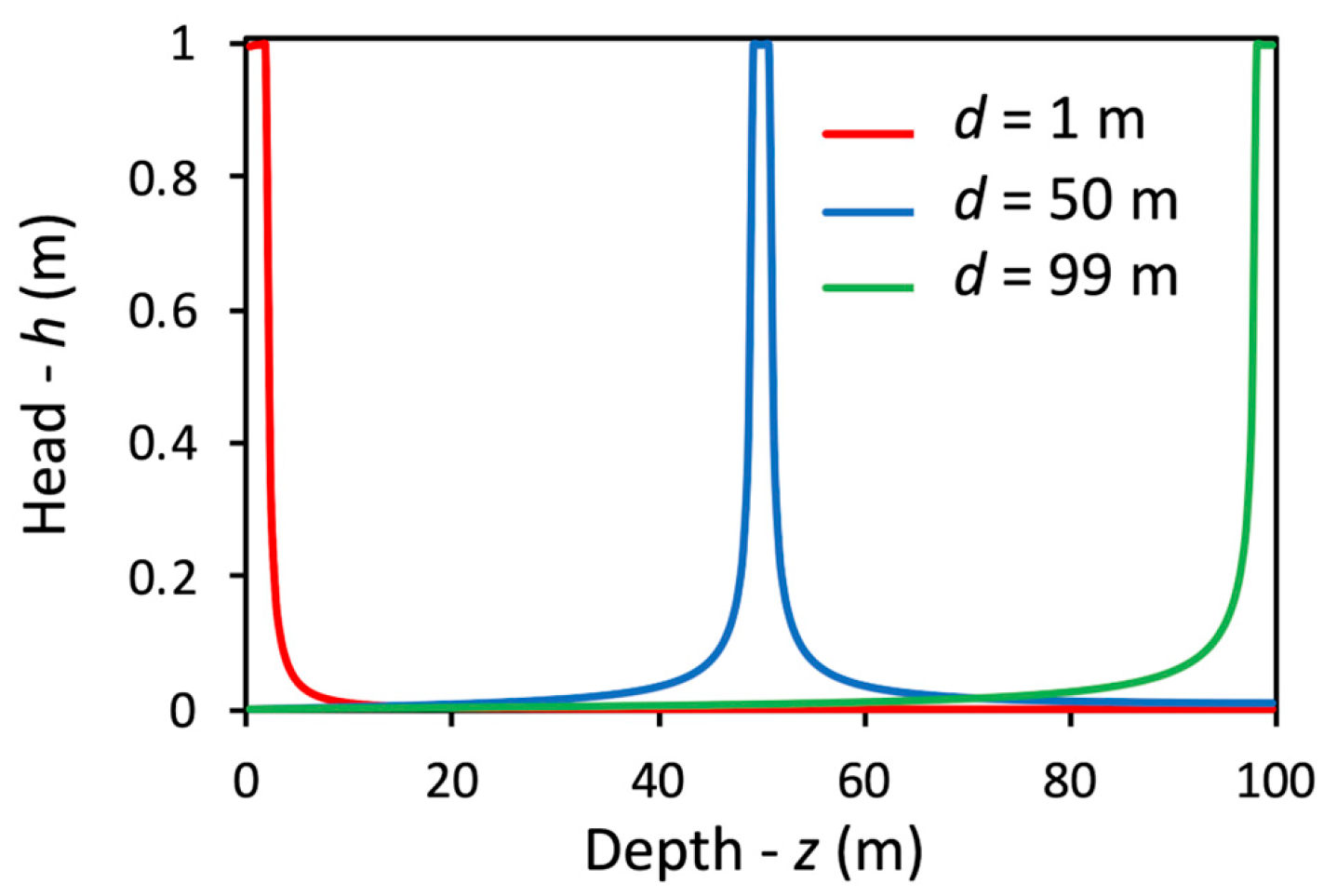
Figure 5 shows the profiles of the head h ( r w , z ) along the well, obtained by inverse finite Fourier sine transform of h n , for the same cases as above. Note the abrupt decrease of the head at the edges of the well screen. The head distribution is fairly symmetrical for a well screen in the center of the aquifer. For a screen at the top of the aquifer, just below the water table, the decrease in head is steeper, while for a screen at the bottom of the aquifer, just above the impervious base, the decrease in head is milder. These findings agree and complement the findings regarding the flow distributions discussed above.

4.3. Effects of Truncation Value and Tolerance

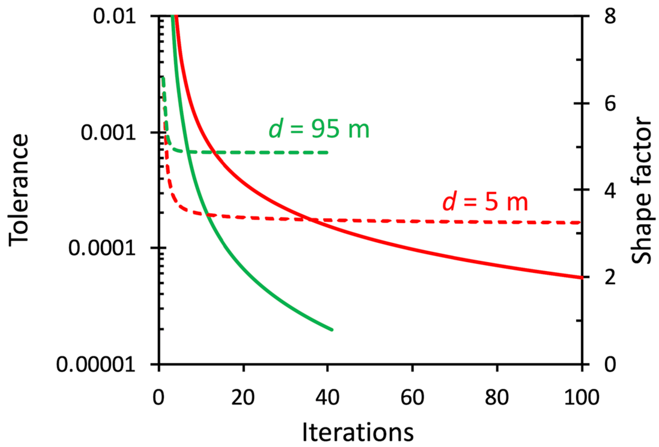
The present results are obtained with a truncation value of 20,000 and a tolerance of 2.10–5. Figure 6 shows the tolerance and shape factor values versus the number of iterations in the solution procedure for a well screen with a length of 10 m that is placed just below the water table (d = 5 m) and just above the impervious base of the aquifer (d = 95 m). The total number of iterations required to reach a tolerance of 2.10–5 is 41 for a depth of 95 m and 446 for a depth of 5 m (note that the x-axis is truncated to 100). The numerical procedure is thus more demanding for shape factors near the water table than near the impervious boundary. For intermediate depths, the number of iterations required to meet the tolerance is between these values. However, Figure 6 shows that shape factor values converge much faster, and thus can be obtained accurately with fewer iterations and a smaller tolerance. The reason for this is that the shape factor mainly depends on the total flow through the well screen, while the distribution of the flow through the screen is less important. De Smedt [16] also noted that the asymptotic behavior of the flux at the edges of the screen has little influence on the overall flow through the well screen.
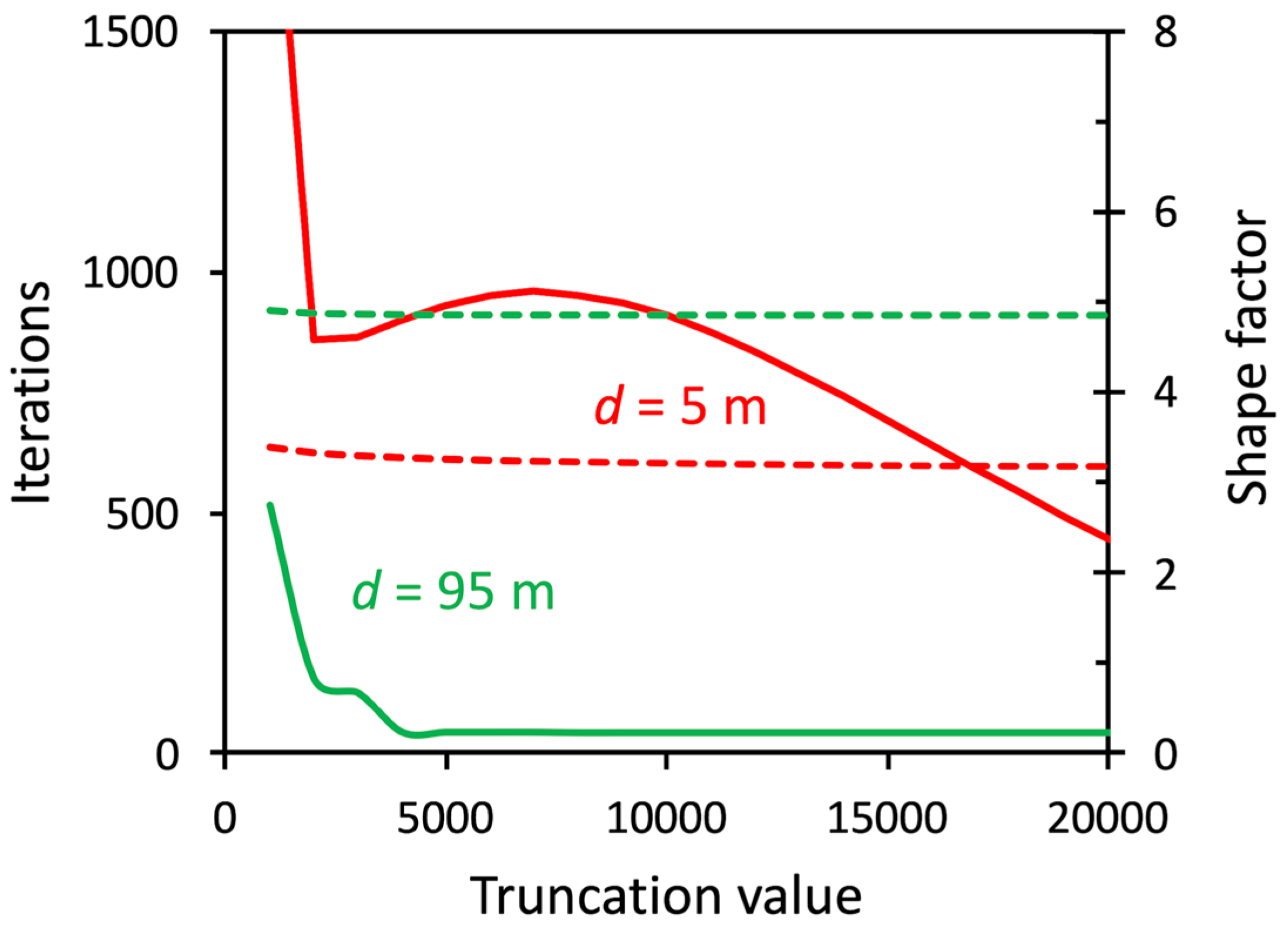
Figure 7 shows the total number of iterations required to meet a tolerance of 2.10–5, and the resulting shape factor values versus truncation value used in the solution procedure for the same conditions as above. It appears that the higher the truncation number, the lower the number of iterations that are required to meet the tolerance, suggesting there is a tradeoff in computational effort. However, truncation values that are too low lead to inaccurate shape factors, especially when the derivation is difficult, such as close to the water table. For a 95 m depth, a truncation number of 8000 and approximately 41 iterations are sufficient to obtain an accurate shape factor value, while for a 5 m depth, a truncation number of 20,000 and 446 iterations are needed to achieve an accurate shape factor value.

4.4. Field Examples

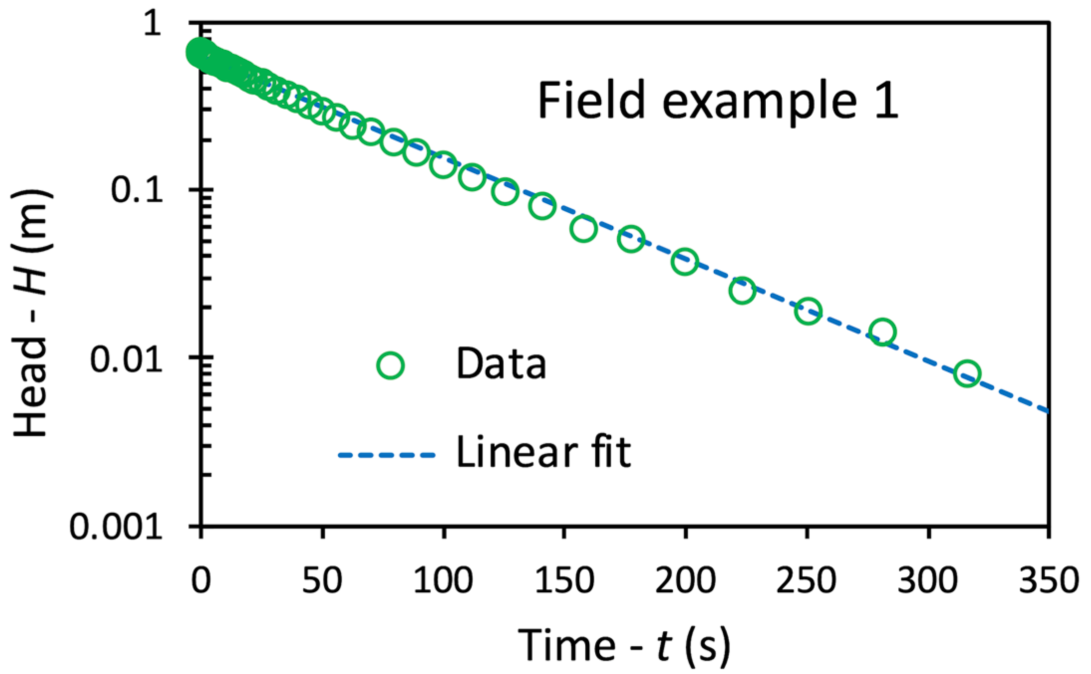
To demonstrate the usefulness in practice, some field examples are considered. The first example is taken from Butler [1] (p. 108). The slug test was performed in an unconfined aquifer with a thickness of 50.6 m. The well screen had a radius of 0.125 m and a length of 1.52 m, and the top of the well screen was at a depth of 18.59 m below the water table so that the well screen was far from the aquifer boundaries. The well and aquifer parameters are summarized in Table 1. The initial head displacement in the well was 0.67 m and the differences in head were monitored for about 6 min. A plot of the log head data versus time is given in Figure 8 and shows a nearly linear decline, indicating that aquifer storage can be ignored. The slope of the fitted straight line is –0.014 s–1. Table 2 shows the shape factor values obtained using different methods and the resulting hydraulic conductivity values obtained using Equation (2). The results are comparable. The differences confirm the previous findings suggesting that Bouwer and Rice’s method is less accurate, Zlotnik et al.’s method is accurate because the well screen is far from the water table and the lower impermeable boundary, and Hvorslev’s method is inaccurate, but that the correction given by De Smedt [16] gives a better agreement, indicating that aquifer boundaries have little effect.
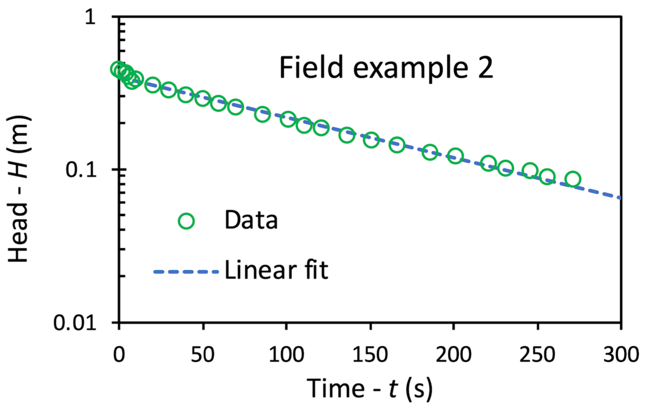
The second example is taken from Batu [22] (p. 654). A falling-head slug test was performed in an unconfined aquifer close to the water table. The thickness of the aquifer was 9.93 m. The well screen had a radius of 0.127 m and a length of 4.21 m, and the top of the well screen was 0.14 m below the water table. All relevant parameters are listed in Table 1. The initial head displacement in the well was 0.45 m and the differences in head were monitored for about 5 min. The plot of the log head data versus time, given in Figure 9, shows that the data can be fitted by a straight line with a slope of –0.006 s–1. Shape factor values obtained using different methods and the resulting hydraulic conductivity values are listed in Table 2. The differences indicate that the method of Bouwer and Rice and the method of Zlotnik et al. deviate by 7–8%, which can be explained by the fact that the well screen is located very close to the water table. This also explains the large differences resulting from the methods of Hvorslev and De Smedt [16]. The proximity to the water table therefore has a marked influence on the shape factor.
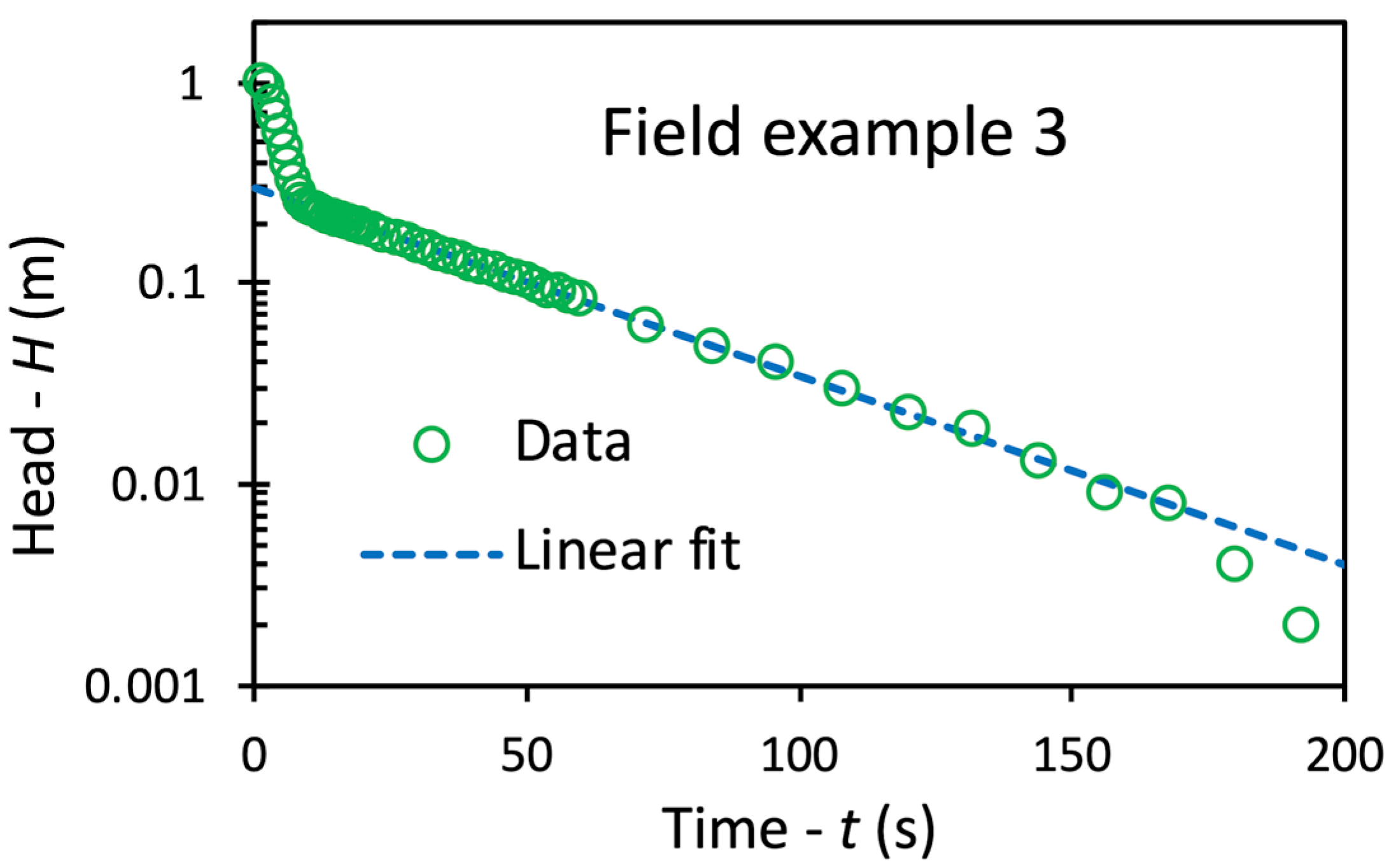
The third example is from Butler [1] (p. 125). This slug test was performed at a former landfill with a saturated thickness of 2.44 m. The well screen, with a radius of 0.026 m and surrounded by an artificial filter pack with an outer radius of 0.105 m, extended over the entire thickness of the landfill and above the water table. All relevant parameters are given in Table 1. Water was removed from the well to a depth of about 1 m and the subsequent rise of the water level in the well was monitored for about 6 min. In a first phase, water drained very quickly from the filter pack to the well until the water levels in the well and the filter pack were equal. This was followed by a second phase in which the water levels rose together due to the inflow of water from the drainage of the landfill. As such, the inner radius r c , used in Equation (2) to derive the hydraulic conductivity of the landfill, must be corrected to include the pore space of the filter pack, as shown by Butler [1] (pp. 124–125).
The plot of the log head data versus time, given in Figure 10, clearly shows the very rapid rise in head due to drainage of the filter pack and the subsequent much slower rise in head due to the drainage of the landfill, with the latter being a function of the hydraulic properties of the landfill. The second phase can thus be used to estimate the hydraulic conductivity of the landfill. These data can be fitted by a straight line with a slope of –0.022 s–1 as shown in Figure 10. The resulting shape factors and estimates of the hydraulic conductivity are given in Table 2. The differences between the results obtained with the method presented in this study and the other methods are substantial, i.e., 40–90%. It is clear that these differences are due to the fact that the well screen and filter pack extend from the bottom to the top of the landfill, resulting in a very non-uniform flow into the well.

5. Conclusions

In this study, an exact solution was presented to derive shape factors for slug tests performed in partially penetrating wells in unconfined aquifers, assuming aquifer storativity can be ignored. The main improvement is that the solution is based on mixed boundary conditions with zero flux at the well casing and constant head at the well screen equal to the head in the well. Comparison with other methods shows that the results are very close to Zlotnik et al. [5], with the exception of the slug tests near the water table because flow through the well is strongly non-uniform. The differences with the Bouwer and Rice [3] method are larger, suggesting that their experimental results, although accurate, were poorly interpolated because abrupt variations near aquifer boundaries were ignored. The effects of boundary conditions are very local and can be ignored when the distance is greater than about three times the screen length. In such a case, shape factors can be approximated with Hvorslev’s approach [2], or better yet, with De Smedt’s [16] method.
The method is based on several simplifying assumptions, such as homogeneous and isotropic aquifer conditions, negligible storage in the aquifer, and no resistance due to well skin. Such conditions are not guaranteed in practice, limiting this method’s utility for a broader range of hydrogeological settings. Furthermore, a more detailed uncertainty analysis would be useful to fully understand the reliability of the method’s outcomes in view of possible errors in input parameters or the impact of assumptions. The study mainly focuses on unconfined aquifers with negligible storativity, limiting its relevance to other types of aquifers or more complex hydrogeological conditions. A more extensive validation across different types of aquifers and geological settings is therefore needed to establish the method’s robustness and versatility. The computational method requires an iterative process to achieve accurate shape factor estimates, especially near the water table. This computational complexity may limit the applicability of the method, particularly in field applications where resources and computational power may be constrained.

Funding

This research received no external funding.

Data Availability Statement

No new data were created.

Conflicts of Interest

The author declares no conflicts of interest.

Appendix A

The computer code to evaluate the shape factors according to the method discussed in the paper is presented in the form of a function written in FORTRAN 95. The arguments of the function (input parameters) are as follows:
  • r: outer radius of the well screen or gravel pack;
  • l: half-length of the well screen;
  • d: depth from the water table to the center of the well screen;
  • b: saturated thickness of the aquifer (depth from the water table to the impervious base);
  • tol: tolerance for the maximum error in the iteration procedure;
  • nmax: truncation number used in the solution procedure.
Notes and guidelines:
  • The unit of the length parameters (r, l, d, b) must be consistent, preferably in meters.
  • The program requires external functions “bessel_K0” and “bessel_K1”, which must be provided by the user.
  • Instruction “parameter:: itmax = 2000” sets the maximum number of iterations of the solution procedure to 2000, but this can be changed by the user.
  • The approximation “beta(n) = (1.0 − (0.5−…)” was obtained from WolframAlpha.
  • Instruction “print*, it, emax, shapefactor” prints the maximum error and the shape factor during the iteration process, but it can be deleted by the user.
  • Instruction “print*, ‘Maximum iterations reached’” informs the user that the maximum number of iterations has been reached before the tolerance is met, but it can be deleted by the user.
  • The program needs sufficient computation time, which depends on the input parameters and the capacity of the computer.
  • The user is advised to repeat calculations with different tolerance and truncation values to verify the results.
Computer code for function shape factors written in FORTRAN 95:


Real function shapefactor(r,l,d,b,tol,nmax)

!Calculate the shape factor of a partially penetrating well
!in an unconfined aquifer
!22/07/2024 Florimond De Smedt
!r: well filter radius
!l: well filter half-lenght
!d: depth to well filter center
!b: aquifer thickness
!tol: error tolerance
!nmax: truncation number

implicit none
integer, intent(in) :: nmax
integer :: it,n,m
integer, parameter :: itmax = 2000 !Can be changed by the user
real, intent(in) :: b,d,l,r,tol
real :: an,beta(nmax),beta1,c(0:2*nmax),e(nmax),emax,f(nmax),q(nmax),sumq
real, parameter :: pi = 4.0*atan(1.0)
real :: bessel_K0,bessel_K1 !External functions provided by the user

!Coefficients
do n=1,nmax
     an = pi*(n−0.5)/b
     f(n) = 4.0*sin(an*d)*sin(an*l)/(an*b)
     q(n) = 0.0
     if(an*r < 40.0) then
          beta(n) = bessel_K0(an*r)/(an*r*bessel_K1(an*r))
     else
          beta(n) = (1.0-(0.5–3.0/(8.0*an*r))/(an*r))/(an*r)
     end if
end do
beta1 = beta(1)
do n=1,nmax
     beta(n) = beta(n)/beta1
enddo
c(0) = 2.0*l/b
do n=1,2*nmax
     an = (n*pi)/b
     c(n) = 2.0*cos(an*d)*sin(an*l)/(an*b)
end do

!Iteration
do it=1,itmax
     do n=1,nmax
          e(n) = f(n)
          do m=1,nmax
              e(n) = e(n)-(c(abs(n-m))-c(n+m−1))*beta(m)*q(m)
          end do
     end do
     emax = 0.0
     sumq = 0.0
     do n=1,nmax
          q(n) = q(n)+e(n)
          emax = max(abs(e(n)),emax)
          sumq = sumq+f(n)*q(n)
     end do
     shapefactor = 4.0*beta1*l/(b*sumq)
     print*,it,emax,shapefactor !Optional (can be deleted)
     if(emax < tol) exit
end do
if(it > itmax) print*,‘Maximum iterations reached’
                                   !Optional (can be deleted)
return
end function shapefactor

References

  1. Butler, J.J., Jr. The Design, Performance, and Analysis of Slug Tests, 2nd ed.; CRC Press: Boca Raton, FL, USA, 2020; p. 266. [Google Scholar]
  2. Hvorslev, M.J. Time Lag and Soil Permeability in Ground-Water Observations; Bulletin 36; Waterways Experimental Station, Corps of Engineers, U.S. Army: Vicksburg, MS, USA, 1951; 50p. [Google Scholar]
  3. Bouwer, H.; Rice, R.C. A slug test for determining hydraulic conductivity of unconfined aquifers with completely or partially penetrating wells. Water Resour. Res. 1976, 12, 423–428. [Google Scholar] [CrossRef]
  4. Dagan, G. A note on packer, slug, and recovery tests in unconfined aquifers. Water Resour. Res. 1978, 14, 929–934. [Google Scholar] [CrossRef]
  5. Zlotnik, V.A.; Goss, D.; Duffield, G.M. General steady-state shape factor for a partially penetrating well. Groundwater 2010, 48, 111–116. [Google Scholar] [CrossRef] [PubMed]
  6. Hyder, Z.; Butler, J.J., Jr.; McElwee, C.D.; Liu, W. Slug tests in partially penetrating wells. Water Resour. Res. 1994, 30, 2945–2957. [Google Scholar] [CrossRef]
  7. Brand, E.W.; Premchitt, J. Shape factors of cylindrical piezometers. Géotechnique 1980, 30, 369–384. [Google Scholar] [CrossRef]
  8. Wilkinson, D.; Hammond, P.S. A perturbation method for mixed boundary-value problems in pressure transient testing. Transp. Porous Media 1990, 5, 609–636. [Google Scholar] [CrossRef]
  9. Widdowson, M.A.; Molz, F.J.; Melville, J.C. An analysis technique for multilevel and partially penetrating slug test data. Groundwater 1990, 28, 937–945. [Google Scholar] [CrossRef]
  10. Ratnam, S.; Soga, K.; Whittle, R.W. Revisiting Hvorslev’s intake factors with the finite element method. Géotechnique 2001, 51, 641–645. [Google Scholar] [CrossRef]
  11. Demir, Z.; Narasimhan, T.N. Improved interpretation of Hvorslev tests. J. Hydraul. Eng. 1994, 120, 477–494. [Google Scholar] [CrossRef]
  12. Mathias, S.A.; Butler, A.P. An improvement on Hvorslev’s shape factors. Géotechnique 2006, 56, 705–706. [Google Scholar] [CrossRef]
  13. Mathias, S.A.; Butler, A.P. Shape factors for constant-head double-packer permeameters. Water Resour. Res. 2007, 43, W06430. [Google Scholar] [CrossRef]
  14. Klammler, H.; Hatfield, K.; Nemer, B.; Mathias, S.A. A trigonometric interpolation approach to mixed-type boundary problems associated with permeameter shape factors. Water Resour. Res. 2011, 47, W03510. [Google Scholar] [CrossRef]
  15. Silvestri, V.; Abou-Samra, G.; Bravo-Jonard, C. Shape Factors of Cylindrical Piezometers in Uniform Soil. Groundwater 2012, 50, 279–284. [Google Scholar] [CrossRef] [PubMed]
  16. De Smedt, F. Shape Factor for Analysis of a Slug Test. Water 2023, 15, 2551. [Google Scholar] [CrossRef]
  17. Chapuis, R.P. Shape factors for permeability tests in boreholes and piezometers. Groundwater 1989, 27, 647–654. [Google Scholar] [CrossRef]
  18. Zlotnik, V.A. Interpretation of Slug and Packer Tests in Anisotropic Aquifers. Groundwater 1994, 32, 761–766. [Google Scholar] [CrossRef]
  19. Hyder, Z.; Butler, J.J., Jr. Slug tests in unconfined formations: An assessment of the Bouwer and Rice technique. Groundwater 1995, 33, 16–22. [Google Scholar] [CrossRef]
  20. Brown, D.L.; Narasimhan, T.N.; Demir, Z. An evaluation of the Bouwer Rice method of slug test analysis. Water Resour. Res. 1995, 31, 1239–1246. [Google Scholar] [CrossRef]
  21. Rupp, D.E.; Selker, J.S.; Simunek, J. A Modification to the Bouwer and Rice Method of Slug-Test Analysis for Large-Diameter, Hand-Dug Wells. Ground Water 2001, 39, 308–314. [Google Scholar] [CrossRef] [PubMed]
  22. Batu, V. Aquifer Hydraulics: A Comprehensive Guide to Hydrogeological Data Analysis; John Wiley & Sons Inc.: Hoboken, NJ, USA, 1998; p. 727. [Google Scholar]
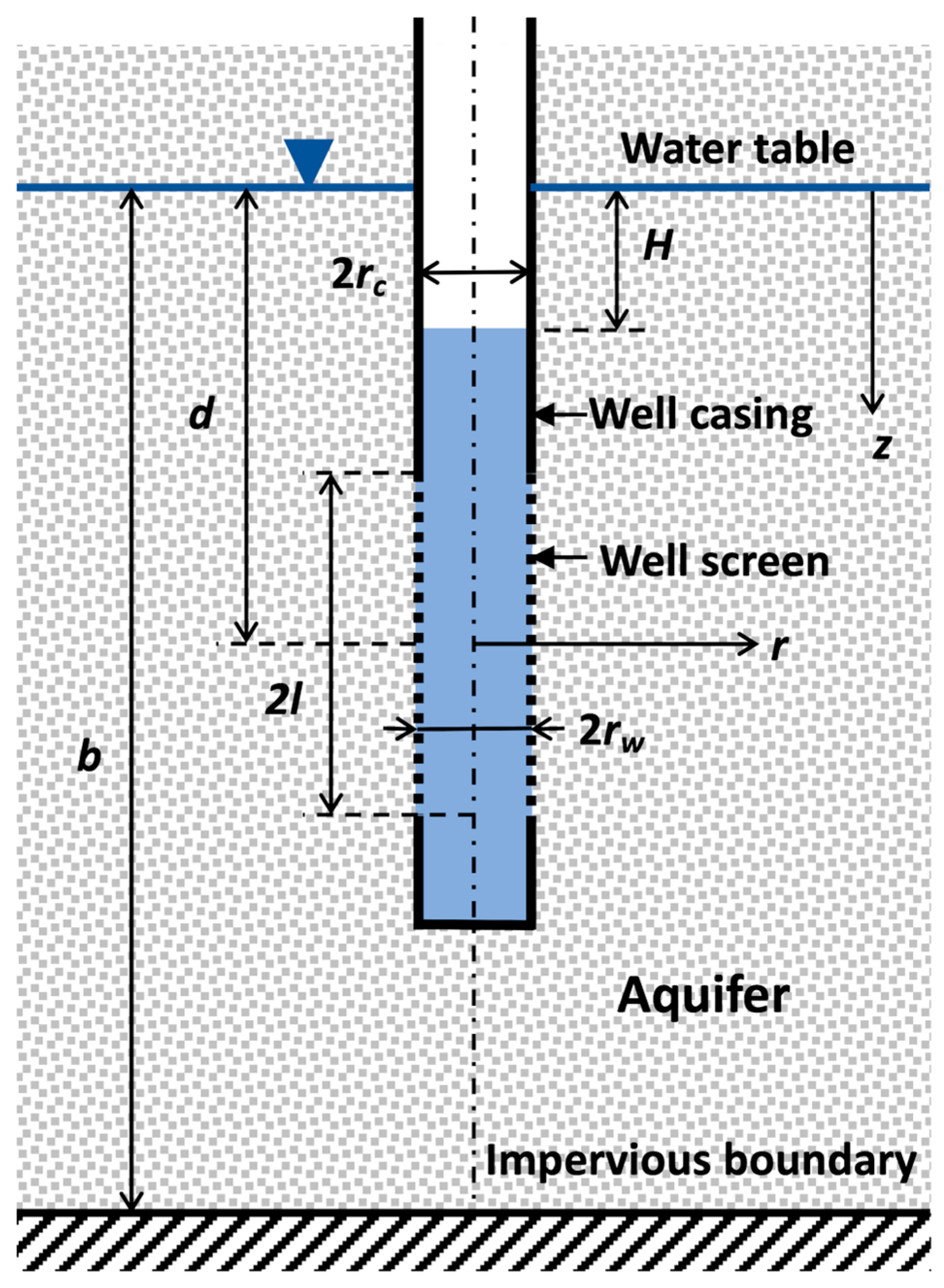
Figure 1. Schematic diagram of a partially penetrating well in an unconfined aquifer: rc, inner radius of the well casing; rw, outer radius of the well screen; l, half-length of the screen; d, depth from the water table to the center of the well screen; b, saturated thickness of the aquifer; H, difference in head in the well; and r and z, radial and vertical coordinates.
Water 16 02853 g001
Figure 2. Plot of shape factor l o g R e / r w versus depth d to the center of the well screen for a partially penetrating well in an unconfined aquifer of 100 m thickness. Results are shown for a screen with a radius rw = 0.1 m and a length L = 2 m (bottom) or L = 10 m (top), obtained using the methods of Bouwer and Rice [3], Zlotnik et al. [5], and this study.
Water 16 02853 g002
Figure 3. Plot of shape factor l o g R e / r w versus screen length L for a partially penetrating well in an unconfined aquifer of 100 m thickness. Results are shown for a screen with a radius rw = 0.1 m positioned at the top of the aquifer just below the water table, obtained using the methods of Bouwer and Rice [3], Zlotnik et al. [5], and this study.
Water 16 02853 g003
Figure 4. Plot of the hydraulic gradient h ( r w , z ) / r at the well screen for head change in the well H = 1 m and a screen with a radius rw = 0.1 m and a length L = 2 m that is placed just below the water table (d = 1 m), in the middle of the aquifer (d = 50 m), or just above the impervious base (d = 99 m).
Water 16 02853 g004
Figure 5. Plot of head h ( r w , z ) along the well for head change in the well H = 1 m and a screen with a radius rw = 0.1 m and a length L = 2 m that is placed just below the water table (d = 1 m), in the middle of the aquifer (d = 50 m), or just above the impervious base (d = 99 m).
Water 16 02853 g005
Figure 6. Plot of tolerance (solid lines) and shape factor values (dashed lines) versus number of iterations used in the solution procedure for a screen with a length of 10 m that is placed just below the water table (d = 5 m) or just above the impervious base (d = 95 m).
Water 16 02853 g006
Figure 7. Plot of the total number of iterations (solid lines) needed to meet a tolerance of 2.10–5 and shape factor values (dotted lines) versus the truncation value used in the solution procedure, for a screen with a length of 10 m, placed just below the water table (d = 5 m) or just above the impervious base (d = 95 m).
Water 16 02853 g007
Figure 8. Plot of the logarithm of observed head H versus time for field example 1, taken from Butler [1] (p. 108).
Water 16 02853 g008
Figure 9. Plot of the logarithm of observed head H versus time for field example 2, taken from Batu [22] (p. 654).
Water 16 02853 g009
Figure 10. Plot of the logarithm of observed head H versus time for field example 3, taken from Butler [1] (p. 125).
Water 16 02853 g010
Table 1. Parameter information for the field examples.
Parameter Field Example
123
Aquifer thickness: b (m)50.69.932.44
Screen outer radius: rw (m)0.1250.1270.105
Screen inner radius: rc (m)0.0640.0520.052
Screen half-length: l (m)0.762.101.22
Screen depth: d (m)19.350.941.22
Table 2. Results of the field examples showing the shape factors obtained with different methods, estimated hydraulic conductivity values, and percentage differences with the current solution.
Field
Example
MethodShape FactorHydraulic
Conductivity
K (m/day)
Difference
(%)
1This study2.253.68-
Bouwer and Rice [3]2.013.50–11
Zlotnik et al. [5]2.333.803
Hvorslev [2]2.504.0711
De Smedt [16]2.283.711
2This study2.50.73-
Bouwer and Rice [3]2.320.67–7
Zlotnik et al. [5]2.690.788
Hvorslev [2]3.501.0240
De Smedt [16]3.220.9429
3This study1.671.73-
Bouwer and Rice [3]2.392.4843
Zlotnik et al. [5]2.562.6553
Hvorslev [2]3.153.2689
De Smedt [16]2.882.9973
Disclaimer/Publisher’s Note: The statements, opinions and data contained in all publications are solely those of the individual author(s) and contributor(s) and not of MDPI and/or the editor(s). MDPI and/or the editor(s) disclaim responsibility for any injury to people or property resulting from any ideas, methods, instructions or products referred to in the content.