Article

Diffusion Mechanism of Variable-Rate Grouting in Water Prevention and Control of Coal Mine

1
School of Resources and Geosciences, China University of Mining and Technology, Xuzhou 221116, China
2
China Coal Hydrology Bureau Group Co., Ltd., Handan 056000, China
3
School of Earth Science and Engineering, Hebei University of Engineering, Handan 056000, China
*
Author to whom correspondence should be addressed.
Water 2024, 16(19), 2814; https://doi.org/10.3390/w16192814
Submission received: 18 September 2024 / Revised: 26 September 2024 / Accepted: 1 October 2024 / Published: 2 October 2024

Abstract

:
Regional grouting treatment is an effective technical means to prevent mine water disasters, and the grouting effect is affected by many factors. In actual grouting engineering, the single constant-rate grouting method is often transformed into a variable-parameter grouting process. However, research on grouting rates has been insufficient. This investigation focused on the issue of “the diffusion law of variable-rate grouting slurry in regional governance”. Methods such as theoretical analysis, numerical simulation, and field verification were used to evaluate the diffusion mechanism of variable-rate fracture grouting. The results indicated that the key parameters of variable-rate grouting, such as slurry diffusion distance and grouting pressure, were affected by the grouting rate. The decrease in the grouting rate reduced the migration speed of the slurry and the grouting pressure. The time for constant-velocity grouting and variable-velocity grouting to reach the same diffusion distance was 60 s and 108 s, respectively, which can be achieved with lower grouting pressure. When the grouting rate was 7.5 L/min and 30 L/min, the maximum grout diffusion distance was 2.81 m and 5.64 m, respectively, which required greater grouting pressure. The slurry diffusion rate decreased with the reduction in the grouting rate. Under the same diffusion distance conditions, variable-rate grouting took longer than constant high-rate grouting. In variable-rate grouting, the grouting pressure decreased stepwise with the grouting rate, with a final pressure drop of 77.4%. In grouting practice, the innovative use of the rate-reducing grouting method can greatly reduce the final grouting pressure under the premise of changing the slurry diffusion distance less, which can not only ensure the stability of surrounding rock but also reduce the cost of high-pressure grouting and the risk of grouting operation. The investigation results can provide scientific guidance for ground grouting renovation projects in deep coal mine water hazard areas.

1. Introduction

Fossil fuels will still be an important source of energy in the future, but there will be a series of problems that threaten their safe development in the development process [1,2]. The hydrogeological conditions of the Carboniferous–Permian coalfields in North China are complex, with frequent water inrush accidents. Coal resource extraction is severely threatened by water hazards, which intensify with increased mining depth, intensity, speed, and scale [3]. To safely extract coal resources, regional grouting reinforcement or transformation of aquifers in the coal seam floor was carried out to seal fissures between the coal seam and the aquifer, enhance the tensile strength of water-resistant rock layers, and prevent water hazards from coal seam floor inrushes [4,5]. In recent years, the application of regional advanced governance technology based on horizontal directional drilling has provided new solutions for controlling Ordovician limestone karst water hazards (Figure 1). This technology has been widely applied in the prevention and control of coalfield floor karst water hazards [6]. Extensive engineering practices have been conducted in the thick limestone water control in the coal seam floors of North China and thin limestone water control in the eastern regions [7,8,9,10]. The “Coal Mine Water Prevention and Control Regulations” issued in 2018 further promoted the application of advanced governance technology by suggesting the use of ground regional governance or local grouting reinforcement of the floor water-resistant layer and transformation of aquifers when conditions for drainage pressure reduction and curtain grouting are not met [11].
The effectiveness of regional grouting governance in controlling coal seam floor karst water hazards is influenced by factors such as hydrogeological conditions, grouting materials, grouting processes, and engineering layout. Previous studies have established theoretical models for slurry diffusion in different grouting hole structures (vertical and horizontal) [12], different fissure properties (horizontal and inclined, smooth and rough) [13,14], and different slurry types (Newtonian and Bingham fluids) [15,16,17]. Experimental studies on grouting materials such as cement, clay, and fly ash-based slurries under various mix ratios have been conducted to examine slurry strength, time dependence, and stone rate [18,19,20]. However, in actual grouting engineering, the underground conditions are complex, and there is difficulty in accurately detecting fissure sizes and scales. In particular, the coal seam floor has multiple layers of water-rich limestone and is close to the coal seam, which is easily affected by faults and other factors to produce a close hydraulic connection (the Yeqing limestone aquifer is about 44 m away from the 2# coal seam floor). The North China coalfield structure type is complicated; the grouting parameters must be adjusted at all times to avoid higher grouting pressure destroying the integrity of the structural zone and the rock layer during the grouting process. The single constant-rate grouting method transforms into a more complex variable-parameter grouting process, directly impacting important aspects such as grouting branch hole spacing, density design, and slurry diffusion range [10,21]. While parameters like grouting pressure, grouting amount, and water–cement ratio are often pre-designed, their impact on slurry diffusion distance has been studied [22]. Lin et al. studied the optimization of grouting efficiency in goaf by three-dimensional numerical simulation [23]. Zhu et al. studied the random fracture grouting mechanism considering the time-varying characteristics of viscosity [24]. Liu et al. studied the mechanism of diffusion and the plugging of dynamic water grouting slurry in karst pipelines [25]. However, there has been little exploration of the grouting rate during the grouting process.
The grouting rate refers to the volume of grouting mixture injected per unit of time, usually measured in liters per minute (L/min). In civil engineering, grouting is a common process used for foundation, tunnel, pit, and traffic tunnel reinforcement projects. By filling existing structural gaps or defects with the mixture, a solid structural system is formed. The grouting rate directly determines the reinforcement effect. Generally, a higher grouting rate allows the mixture to flow into the structure more quickly but also affects the mixture quality. Therefore, appropriate grouting rates must be chosen based on actual conditions in engineering practice. For instance, to prevent excessive grouting pressure from causing rock fractures and creating new fissure networks—or from causing rock fractures leading to sudden pressure drops, increased grouting costs, or even collapses and water inrushes—a reduced grouting rate method is typically used to lower the final grouting pressure and protect rock stability. Compared to constant-rate grouting, reasonable variable-rate grouting can avoid the phenomenon of blockage and slurry leakage in the grouting process and prevent the phenomenon of slurry stratification caused by the constant rate. More importantly, it is very likely to cause the failure of grouting engineering and even secondary disasters by using traditional constant-rate grouting in the more developed areas. The key parameters such as slurry diffusion distance, grouting pressure, or grouting rate in variable-parameter fracture grouting exhibit different variation patterns.
Therefore, focusing on the key scientific issue of “the diffusion law of variable-rate grouting slurry in regional governance,” this study investigated the impact of grouting rates on slurry diffusion in actual grouting projects. According to the principles of combining theory with practice, combining indoor and field, and carrying out repetitive tests, the methods of theoretical analysis, numerical simulation, and field verification were comprehensively adopted. The commonly used “stagewise descending rate” variable-parameter grouting method was selected for studying the diffusion mechanism of variable-rate fracture grouting. A new variable-rate grouting control method was proposed, which was more in line with the engineering practice, and the slurry diffusion model was constructed. The innovative use of the reduced-rate grouting method can greatly reduce the final pressure of grouting under the premise of a small change in the slurry diffusion distance, which can not only achieve the purpose of ensuring the stability of surrounding rock, but also reduce the cost of high-pressure grouting and the risk of grouting operation. The research results can provide scientific guidance for ground grouting renovation projects in deep-mine water hazard areas.

2. Methodology

In this study, theoretical analysis was used to construct the slurry diffusion control equation, numerical simulation of slurry diffusion rate and distance under constant slurry viscosity, and on-site grouting engineering verification to study the slurry diffusion law under variable-rate grouting conditions.

2.1. Construction of Slurry Diffusion Control Equation

The core of grouting design is to determine key grouting parameters, including slurry properties, fracture width, and grouting rate. Grouting design is primarily based on experiments and theoretical analysis. By establishing a grouting diffusion model and solving the grouting control equation, the diffusion process of grouting slurry in rock fractures was analyzed. Based on an in-depth analysis of factors such as the rheological properties of grouting materials and grouting control methods, a diffusion control equation for single-fracture grouting was established.
(1)
Assumptions
To derive the diffusion control equation for slurry in planar fractures, the following assumptions were made considering the time-varying viscosity of the slurry:
  • The slurry is incompressible and diffuses radially in the fracture, and the flow form is laminar.
  • The upper and lower surfaces of the fracture are undeformed with no-slip boundary conditions, meaning the flow velocity of the slurry at these surfaces is zero.
  • The fracture surfaces are flat and horizontal, with a constant and equal width throughout, and gravity and inertial forces are negligible.
  • The mixing time of the slurry is considered negligible, assuming the slurry mixing time equals the grouting time.
(2)
Construction of the Diffusion Equation
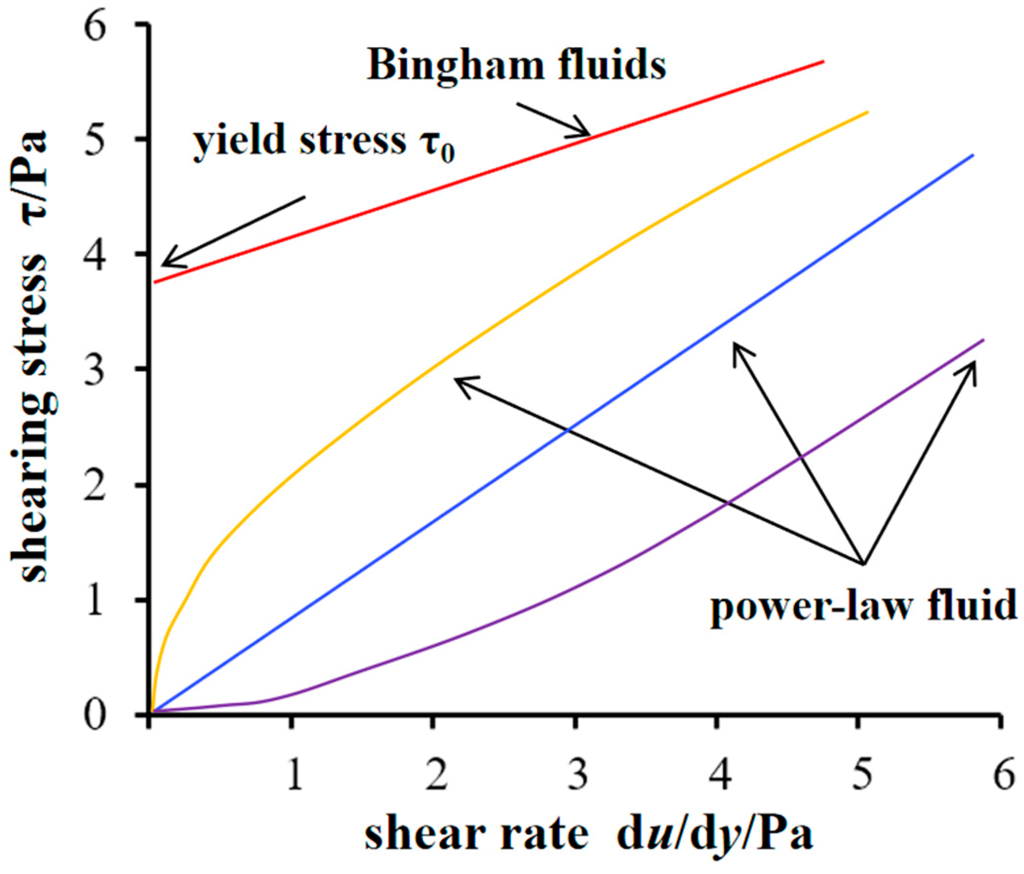
The diffusion of slurry in fractures is a complex process influenced by multiple factors, including grouting materials, fracture size, and grouting methods. To describe the motion state of the slurry, its rheological properties were first analyzed. Fluids are typically classified into Newtonian and non-Newtonian fluids, with non-Newtonian fluids further divided into power-law and Bingham fluids, as shown in Figure 2.
For Newtonian fluids, the shear stress and shear rate have the following linear relationship:
τ = μ d v d r
where τ is the shear stress, μ is the viscosity of the slurry, and dv/dh is the shear rate (velocity gradient) of the slurry.
Bingham fluid is a viscoplastic fluid, which is a rigid material at low shear stress and a viscous fluid when the shear stress is greater than the yield stress:
τ = τ 0 + μ d v d h
where τ0 is the yield stress of the slurry.
As a non-Newtonian fluid, the shear stress and shear rate of power-law fluid satisfy the following relationship:
τ = c d v d h n
where c is the consistency coefficient and n is the flow index.
Assuming that the cement slurry used is a Newtonian fluid, its shear stress and velocity relationship can be expressed using Equation (1).
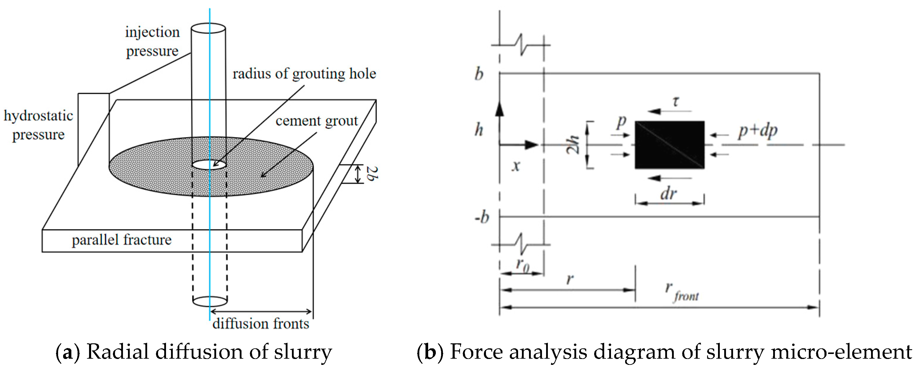
Based on these assumptions, under static water conditions, the slurry diffuses radially from the grouting hole in a planar fracture with the grouting hole as the center. As shown in Figure 3, let the vertical fracture width be 2b, the radius of the grouting hole be r0, the diffusion range of the slurry be limited by the diffusion front with a radius rfront, and the maximum grouting pressure at the grouting hole be pg.
Taking a micro-element of the slurry along the symmetrical axis of the fracture for force analysis, as shown in Figure 3b, the force balance equation for the micro-element at any r is:
2 τ d r + 2 h d p = 0
where dr is the length of the micro-element, p is the slurry pressure, dp is the pressure increment, and 2h is the height of the micro-element.
Combining Equations (1) and (4), the velocity gradient during slurry diffusion can be expressed as:
d v d h = h μ ( t ) d p d r
Given the assumption of incompressible slurry with laminar flow, integrating Equation (5) yields the velocity distribution equation. The constant term in the integration can be eliminated using the boundary condition v (r, ± b) = 0 (based on the no-slip boundary condition). The velocity distribution equation is
v = 1 μ ( t ) b 2 h 2 2 d p d r
where −dp/dr represents the slurry pressure gradient along the diffusion direction.
The average slurry velocity at any diffusion radius r can be expressed as
v m e a n = 1 2 b b b v d h
Substituting Equation (6) into Equation (7) and integrating, the average slurry velocity at any r can be expressed as
v m e a n = b 2 3 μ ( t ) d p d r
According to the principle of mass conservation, the grouting volume per unit time q (i.e., the grouting rate) can be expressed as
q = 4 π r b v m e a n
where q represents the grouting rate.
Substituting Equation (8) into Equation (9) yields the control equation for the slurry pressure gradient within the grouting zone:
d p d r = 3 μ ( t ) q 4 π r b 3
It can be seen from Equation (10) that the spatial distribution of slurry pressure in plate cracks is controlled by factors such as crack size, grouting rate, slurry diffusion distance and slurry rheological characteristics. In order to predict the spatial distribution of slurry pressure at a certain moment in the process of slurry diffusion, it is necessary to further determine the expression of grouting time t and the time-varying viscosity function μ(t).
Given that the slurry diffuses radially within the planar fracture, the slurry injection volume Q is equal to the grouting volume diffused within the fracture, and the relationship is
Q = q t = 2 b π r 2 r 0 2
where Q is the cumulative injection amount of slurry.
In engineering practice, the radius of the grouting hole r0 is very small compared with the whole slurry diffusion area, which can be ignored. Therefore, the grouting time t and its corresponding diffusion radius r can be expressed by the following formulae:
t = 2 b π r 2 q
or
r = q t 2 b π
The time-varying viscosity characteristic of the slurry can be tested using a viscometer, and the time-varying viscosity function can be obtained through data fitting. Based on previous experimental results, the time-varying viscosity equation for cement slurry can be represented by the following general formula:
μ ( t ) = μ 0 e k t
where μ0 is the initial viscosity of the slurry, k is the viscosity growth index determined by the type of slurry, and t is the grouting time.
Substituting Equations (13) and (14) into Equation (10), we obtain
d p d r = 3 μ 0 q e k t 4 π r b 3
Integrating Equation (15) within the diffusion range [r,r0], the spatiotemporal distribution equation for slurry pressure in the planar fracture can be expressed as
p ( r , t ) = 3 μ 0 q e k t 4 π b 3 ln ( R r 0 ) + p 0
where p (r,t) is the slurry pressure at any r within the diffusion zone at grouting time t, and p0 is the static water pressure.

2.2. Numerical Simulation of Slurry Diffusion

To further validate the accuracy of the diffusion control equation and explore the diffusion law of the slurry, a numerical model was constructed using the laminar two-phase flow physics field in the COMSOL Fluid Mechanics module. The interface tracking calculation between the slurry and water was performed using the level set method, and the distribution of the slurry and water within the entire computational domain was represented by the volume fraction method. The diffusion rate and distance of the slurry with constant viscosity were simulated.
(1)
Creation of the Computational Model
The finite element geometric model and mesh profile are shown in Figure 4. The finite element model was a three-dimensional model with a fracture thickness of 5 mm, a grouting hole radius of 2 cm, and a distance of 2 m from the grouting hole to the outlet boundary. The grouting hole was set as a constant flow rate boundary where the slurry was injected into the fracture at a constant rate. The left and right sides of the model were no-pressure outflow boundaries with zero pressure, allowing the slurry and water to flow out from these boundaries. The upper and lower boundaries were no-flow boundaries, satisfying the no-slip boundary condition.
(2)
Control Equations
The fluid motion equation adopts the complete form of the Navier–Stokes equation, which describes the constitutive relationship between fluid motion and forces under three-dimensional conditions:
ρ u t + ρ ( u u ) = p I + μ ( t ) ( u + ( u ) T ) + F
where ρ is the fluid density, u is the fluid velocity vector, t is time, p is the fluid pressure, μ(t) is the time-varying viscosity function, F is the body force per unit volume, ∇ is the Hamiltonian operator, and I is the identity matrix. The left side of Equation (17) represents the inertial force per unit volume of the fluid, while the right side’s first term is the viscous force term, and the second term is the body force per unit volume.
Neglecting the compressibility of the slurry and fluid during grouting, the mass conservation equation must be satisfied in any region:
· u = 0
The control equation for the two-phase flow interface is
ϕ t + u ϕ = γ ς I S ϕ ϕ ( 1 ϕ ) ϕ ϕ
where ϕ is the level set variable and ςIS is the parameter controlling the interface thickness.
In this calculation, the viscosity was a constant 3 Pa·s, the grouting rate was 15 L/min, the fracture width was 0.005 m, and the grouting time was 60 s. The calculation stopped once the set time was reached.

2.3. Field Verification of Variable-Rate Grouting

Based on the study of slurry diffusion under variable-rate grouting in fractures, the diffusion law of grouting slurry under staged descending rate grouting was studied, combined with the actual grouting rate in grouting renovation engineering. The variation curves of grouting rate over time, as well as the changes in slurry diffusion distance and grouting pressure over time, were plotted. A comparative analysis of the parameters such as diffusion distance and grouting pressure was conducted between constant-rate grouting and variable-rate grouting.
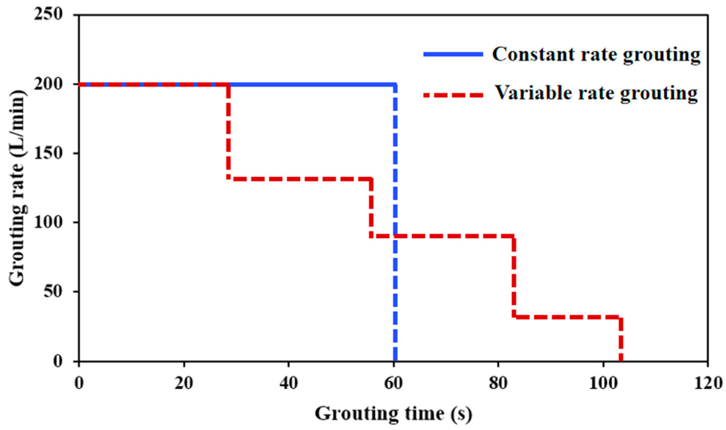
The grouting rate q(t) was set as a piecewise function with rates of 200 L/min, 130 L/min, 90 L/min, and 30 L/min, respectively. Compared to constant-rate grouting, the total grouting volume was kept constant while changing the grouting time for variable-rate grouting. The changes in the grouting diffusion process and grouting pressure under the same diffusion distance conditions were analyzed. The rate adjustment scheme is shown in Figure 5.
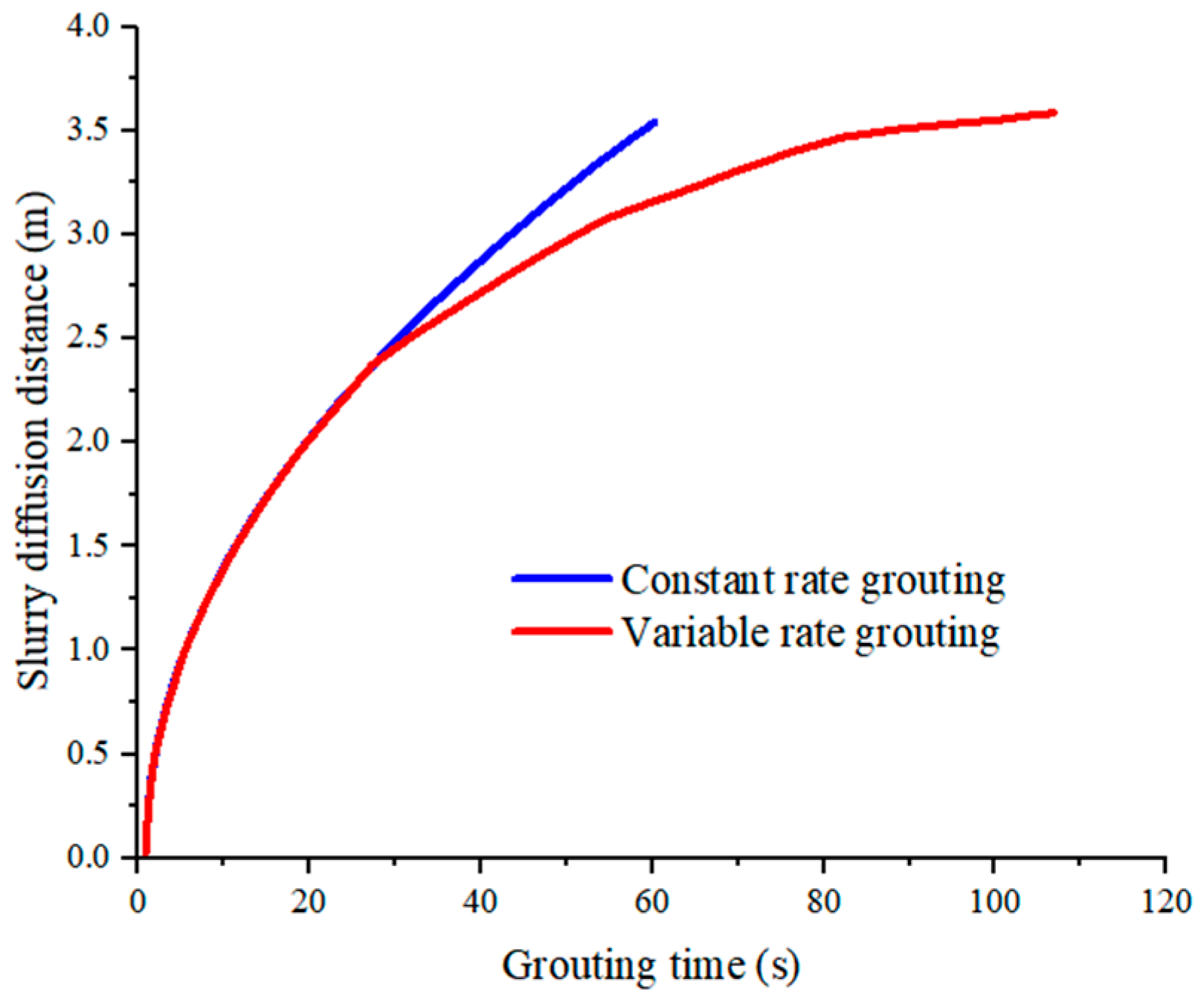
It can be seen from the figure that when the total amount of grouting remained unchanged, the grouting was completed in 60 s when the constant-speed grouting method with a grouting rate of 200 L/min was adopted. When the variable-speed grouting reached the same slurry diffusion distance, the required grouting time was 108 s. In the case of the same slurry diffusion distance, the grouting time required for variable-speed grouting was greater than the constant-speed grouting at the maximum rate, which can effectively prevent hydraulic fracturing of primary karst fractures. This was consistent with the results obtained by the previous formula (12). The grouting time increases with the increase in the grouting radius and the decrease in the grouting rate.

3. Results and Discussion

3.1. Calculation Results and Analysis of Slurry Control Equation

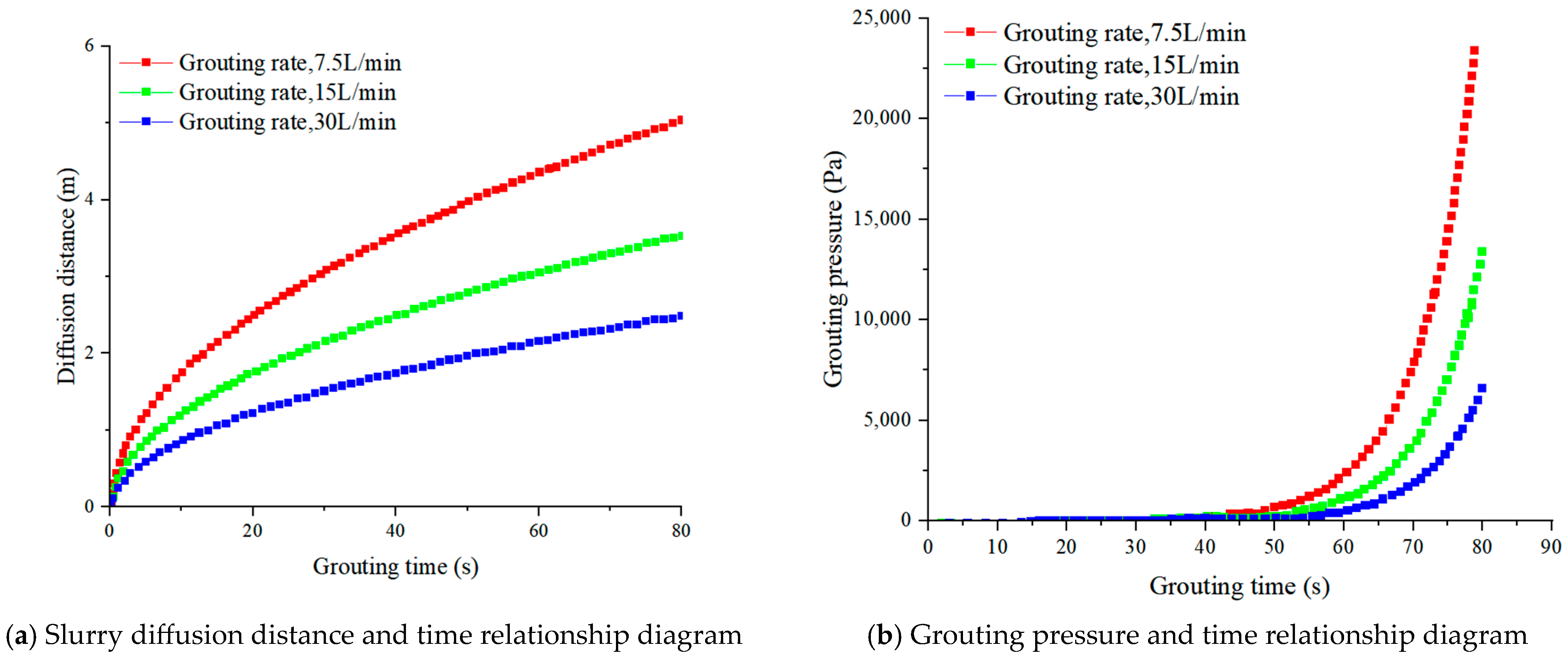
To investigate the effect of the grouting rate on slurry diffusion, the slurry diffusion control equation was used to calculate and plot the relationship between slurry diffusion distance, grouting pressure distribution, and grouting rate, keeping the grouting material and fracture width constant. Grouting rates of 7.5 L/min, 15 L/min, and 30 L/min were selected. The specific design scheme is shown in Table 1.
Analysis of Figure 6 reveals that the maximum diffusion distance of the slurry increases with the grouting rate. When the grouting rate was 7.5 L/min, the maximum diffusion distance was 2.81 m, and it increased to 5.64 m at a rate of 30 L/min. Under the same diffusion distance conditions, the slurry diffusion time was shorter at higher grouting rates, with less change in slurry viscosity and resistance. Higher grouting rates can achieve the required diffusion with lower grouting pressure. The final grouting pressure increases with the grouting rate, mainly because the slurry diffusion range expands with the grouting rate. Consequently, greater grouting pressure was needed to drive the slurry diffusion considering the combined effects of slurry diffusion length and viscosity.
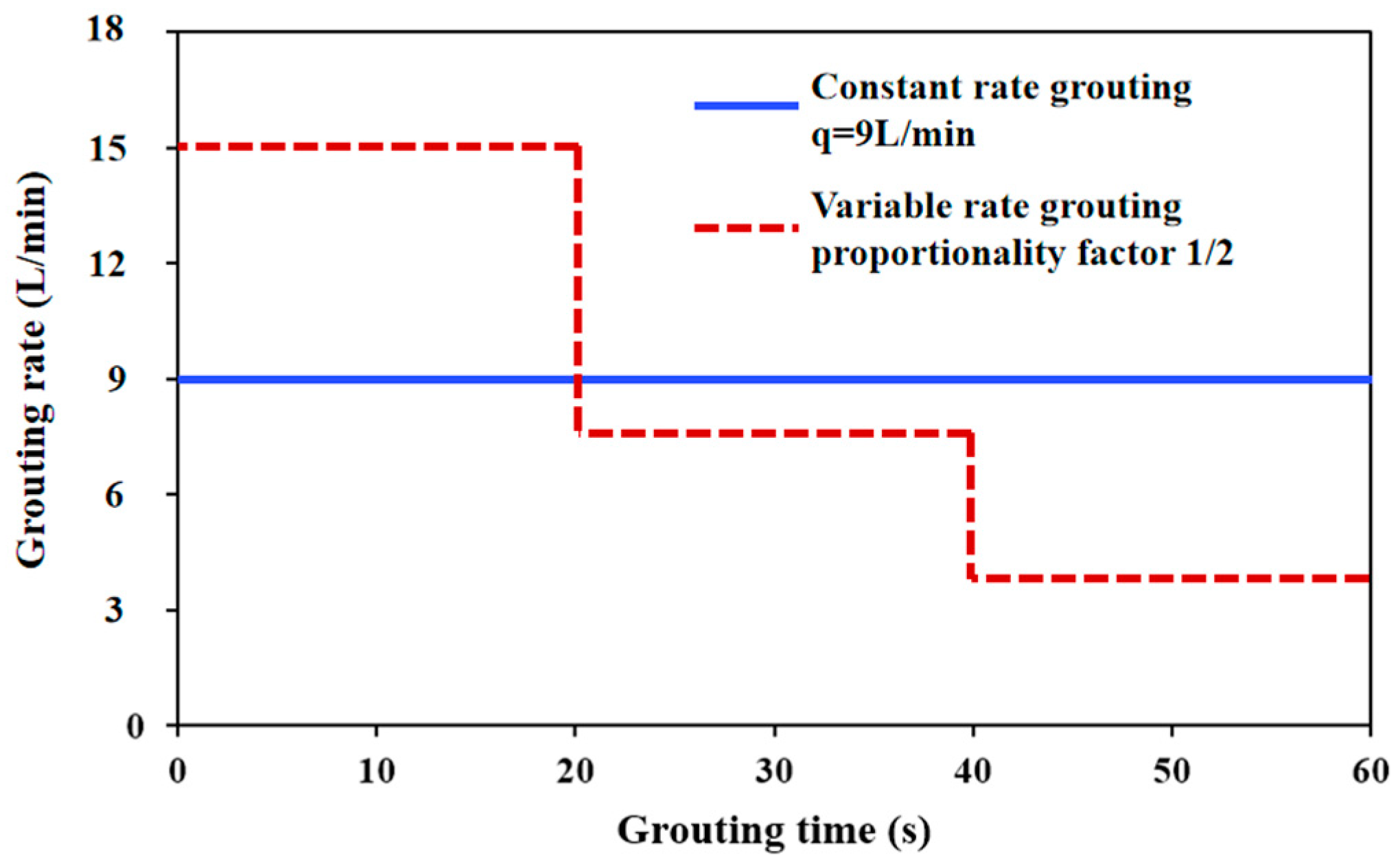
Further, the grouting rate q(t) was set as a piecewise function, dividing the grouting time into several equal intervals, with the grouting rate sequentially reduced by a certain proportional coefficient (e.g., 1/2) in each interval to simulate the actual decreasing-rate grouting process in fractures, as shown in Figure 7.
Additionally, the average grouting rate of each stage was used as a constant rate to compare and analyze the decreasing-rate grouting and constant-rate grouting processes. Specific parameters are shown in Table 2.
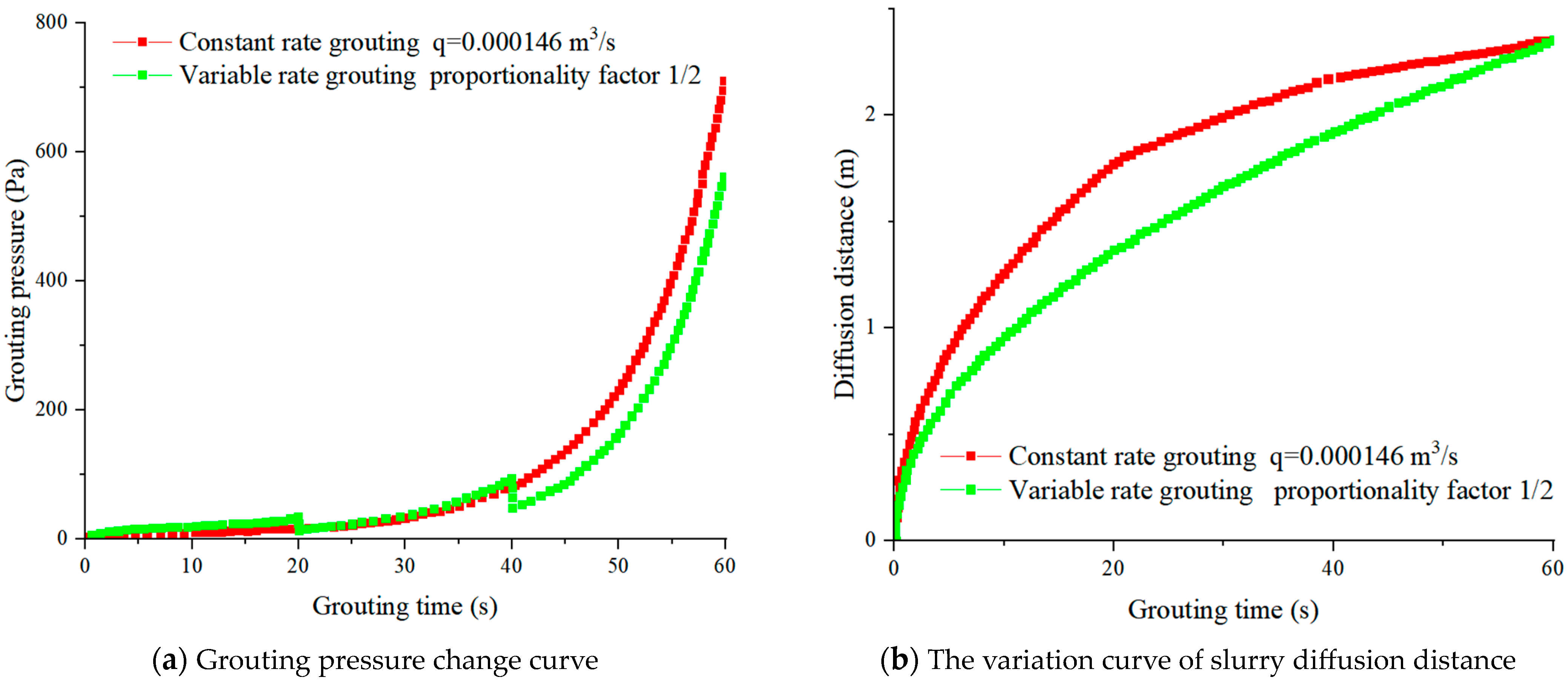
Analysis of Figure 8 indicates that during the staged decreasing-rate fracture grouting process, the slurry diffusion distance and grouting pressure show significant changes due to the varying grouting rate. Comparative analysis between the decreasing-rate grouting and constant-rate grouting processes under the same conditions reveals the following patterns:
When the total grouting time was equal, the slurry diffusion curves in both conditions exhibit a convex shape, with the growth rate of the diffusion distance gradually decreasing. During the decreasing-rate grouting process, the slope of the diffusion curve shows significant “staged” reductions, and the curves converge at the end of grouting with the constant-rate grouting diffusion curve. This indicates that the grouting rate influences the speed of slurry migration in the fracture, but the total grouting volume determines the maximum diffusion distance of the slurry. Therefore, in practical grouting processes, the maximum diffusion distance of the slurry can be calculated using the average grouting rate in staged decreasing-rate grouting.
In decreasing-rate fracture grouting, the grouting pressure increases in a “stepped” manner. Corresponding to each stage, the grouting pressure curve shows a concave shape. Under the same slurry diffusion distance, the final pressure for staged decreasing-rate fracture grouting was 568 Pa, significantly lower than the 719 Pa for constant-rate grouting, representing a reduction of 26.6%. This demonstrates that staged decreasing-rate fracture grouting effectively reduces the final grouting pressure. Thus, in grouting practices, decreasing-rate grouting can be used to reduce final grouting pressure and minimize damage to the surrounding rock.

3.2. Numerical Simulation Results and Analysis of Slurry Diffusion

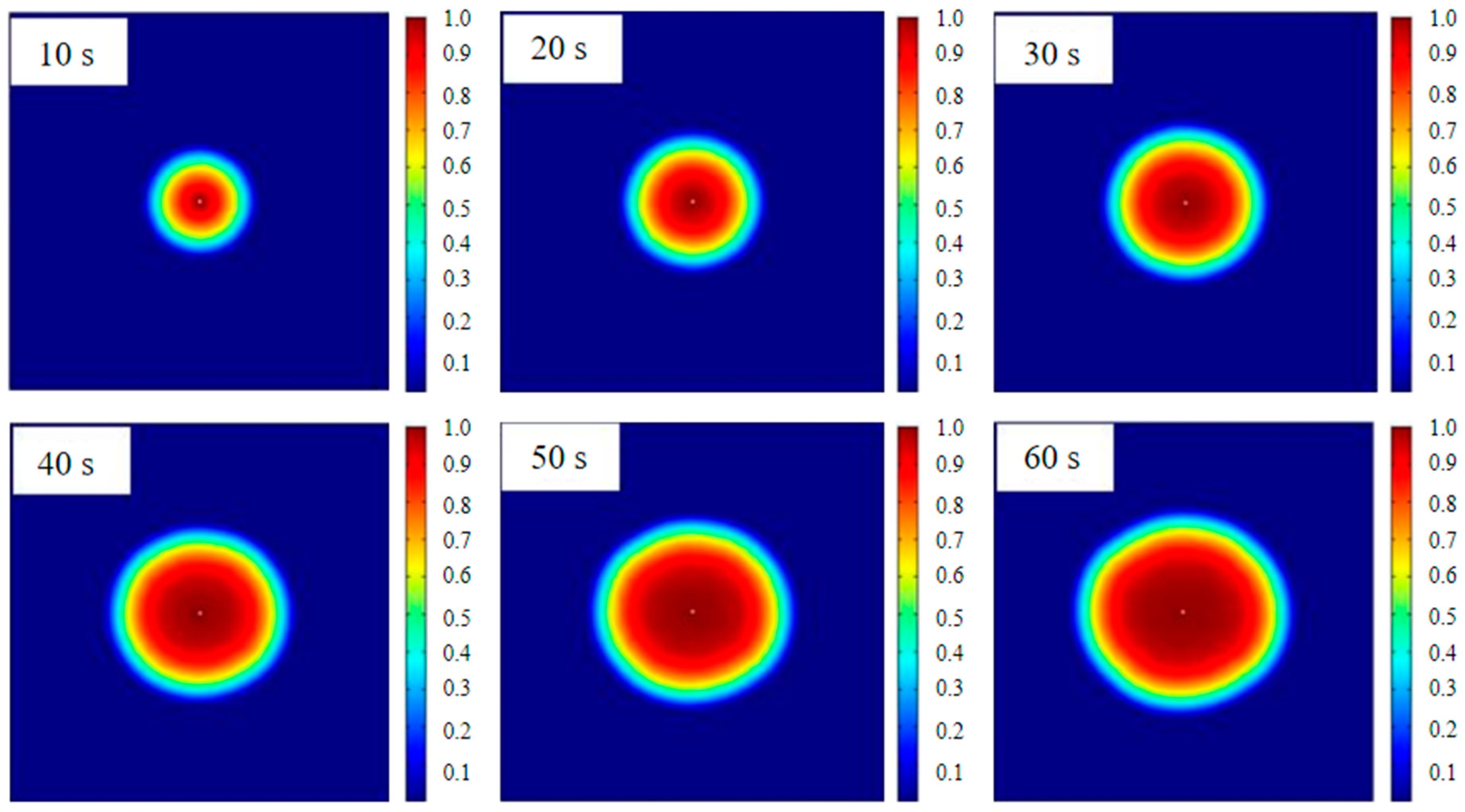
During the numerical simulation, the slurry diffusion morphology was recorded every 10 s, as shown in Figure 9. In the figure, the red area represents the slurry, while the blue area represents water.
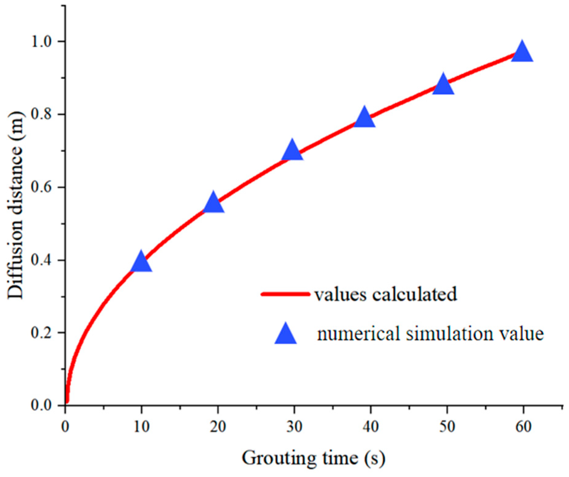
The position of the slurry front was selected as the maximum diffusion distance of the slurry, and the variation law of slurry diffusion distance with time obtained by numerical simulation of slurry diffusion was used to draw Figure 10.
The comparison of results indicates that the calculated results from the slurry diffusion control equation show good consistency with the numerical simulation results. The slurry diffusion distance increases over time in a convex shape. Under constant slurry viscosity, the diffusion rate gradually decreases, primarily due to the expanding radial diffusion radius of the slurry.

3.3. On-Site Monitoring Results and Analysis of Slurry Diffusion

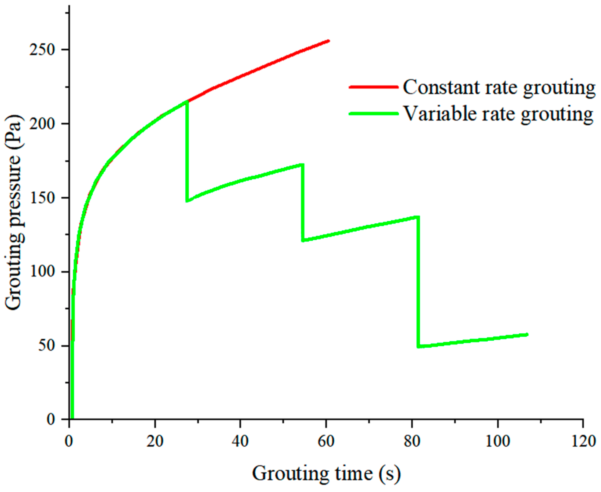
The parameter variation curves of slurry diffusion distance and grouting pressure during the on-site variable-rate grouting process are shown in Figure 11 and Figure 12.
Under constant total grouting volume, the maximum slurry diffusion distance at a constant grouting rate of 198 L/min was 3.58 m after 60 s of grouting. The variable-rate grouting required 108 s to reach the same slurry diffusion distance. Throughout the variable-rate grouting process, the slurry diffusion rate decreased with the reduction in grouting rate. When achieving the same slurry diffusion distance, the variable-rate grouting took longer than the maximum-rate constant grouting.
With a constant grouting rate, the final grouting pressure was 255.75 Pa. For variable-rate grouting, the grouting pressure decreased in a stepped manner with the decreasing grouting rate, resulting in a grouting pressure of 57.84 Pa. Under the same diffusion distance, the final grouting pressure decreased by 77.4%. This was consistent with the results obtained by the previous formula (16), and the grouting pressure is negatively correlated with the grouting time.
The above analysis indicates that during staged decreasing-rate fracture grouting, the response of the final grouting pressure to changes in grouting rate was much greater than that of the slurry diffusion distance. Therefore, in practical grouting, an appropriate decreasing-rate adjustment scheme can be used to significantly reduce the final grouting pressure with minimal changes to the slurry diffusion distance, ensuring the stability of the surrounding rock and effectively preventing hydraulic fracturing of native karst fractures.

4. Conclusions

(1)
When the diffusion distance was the same, the slurry diffusion time was shorter at higher rates. This results in smaller changes in slurry viscosity and less resistance, allowing for the achievement of the required diffusion with lower grouting pressure. As the grouting rate increases, the diffusion range of the slurry expands. Under the influence of slurry viscosity, greater grouting pressure was needed to drive the slurry diffusion.
(2)
The calculation results of the slurry diffusion control equation were similar to the numerical simulation results. The slurry diffusion distance curve exhibits a convex shape over time. With constant slurry viscosity, the diffusion rate of the slurry gradually decreases, mainly due to the expansion of the radial diffusion radius of the slurry.
(3)
The slurry diffusion rate decreases with the reduction in the grouting rate. Under the same slurry diffusion distance conditions, the time required for variable-rate grouting was longer than that for maximum-rate constant grouting. When employing variable-rate grouting, the grouting pressure decreases in a stepped manner with the grouting rate, resulting in a 77.4% reduction in final grouting pressure.
(4)
In grouting practice, a decreasing-rate grouting method can be used to significantly reduce the final grouting pressure with minimal changes to the slurry diffusion distance. This ensures the stability of the surrounding rock and effectively prevents hydraulic fracturing of native karst fractures.

Author Contributions

Author Contributions: Conceptualization, C.L. (Chong Li); resources, C.L. (Chong Li); methodology, C.L. (Chong Li); writing—original draft preparation, C.L. (Cunjin Lu); writing—review and editing, C.L. (Cunjin Lu); funding acquisition, J.X.; project administration, J.X.; data curation, K.Z.; investigation, K.Z.; supervision, S.L.; validation, S.L.; formal analysis, H.Z.; visualization, H.Z. All authors have read and agreed to the published version of the manuscript.

Funding

This project is funded by the Postdoctoral Fellowship Program of CPSF (No. GZC20233005), the General Program of the National Natural Science Foundation of China (No. 52274243), and the Fundamental Research Funds for the Central Universities (No. 2024QN11025).

Data Availability Statement

The data used to support the findings of this study are included within the manuscript.

Conflicts of Interest

Authors Chong Li and Kai Zhang were employed by the company China Coal Hydrology Bureau Group Co., Ltd. The remaining authors declare that the research was conducted in the absence of any commercial or financial relationships that could be construed as a potential conflict of interest.

References

  1. Li, Y.H.; Song, Y.C.; Liu, W.G.; Yu, F.; Wang, R. A new strength criterion and constitutive model of gas hydrate-bearing sediments under high confining pressures. J. Pet. Sci. Eng. 2013, 109, 45–50. [Google Scholar] [CrossRef]
  2. Li, Q.C.; Zhao, D.F.; Yin, J.K.; Zhou, X.Y.; Li, Y.; Chi, P.; Han, Y.; Ansari, U.; Cheng, Y.F. Sediment Instability Caused by Gas Production from Hydrate-bearing Sediment in Northern South China Sea by Horizontal Wellbore: Evolution and Mechanism. Nat. Resour. Res. 2023, 32, 1595–1620. [Google Scholar] [CrossRef]
  3. Zhang, J.L.; Le, Z.J.; Guo, M. Application of coal floor grouting consolidation in Chaochuan coalmine, Ruzhou Coalfield, Henan. Coal Geol. China 2011, 23, 38–41. [Google Scholar]
  4. Zhu, J.Z.; Liu, Y.; Liu, Q.M.; Yang, S.; Fan, J.J.; Gui, Y.; Li, L. Application and evaluation of regional control technology of limestone water hazard: A case study of the Gubei coal mine, North China. Geofluids 2021, 2021, 6661319. [Google Scholar] [CrossRef]
  5. Zhai, M.L.; Bai, H.B. Precise application of grouting technology in underground coal mining: Water inrush risk of floor elimination. Environ. Sci. Pollut. Res. 2023, 30, 24361–24376. [Google Scholar] [CrossRef] [PubMed]
  6. Wu, Q.; Guo, X.M.; Bian, K.; Du, X.; Xu, K.; Bu, W.Y.; Zeng, Y.F. Carrying out general survey of the water disaster–causing factors to prevent the occurrence of coal mine water disasters. China Coal 2023, 49, 3–15. [Google Scholar]
  7. Zhao, Q.B. Technology of Regional Advance Water Prevention and Control Applied to Pressurized Coal Mining Zone Above Ordovician Limestone Karst Water. Coal Sci. Technol. 2014, 42, 253–2336. [Google Scholar]
  8. Zheng, L.G.; Sun, R.Y.; Hintelmann, H.; Zhu, J.M.; Wang, R.W.; Sonke, J.E. Mercury stable isotope compositions in magmatic-affected coal deposits: New insights to mercury sources, migration and enrichment. Chem. Geol. 2018, 479, 86–101. [Google Scholar] [CrossRef]
  9. Zheng, S.T.; Ma, H.W.; Ji, Y.D. Optimization of regional advanced coal floor water hazard prevention and control technology and its application. Coal Geol. Explor. 2021, 49, 167–173. [Google Scholar]
  10. Wang, Q.; Zheng, S.T.; Shi, Z.Y.; Wu, P.; Lv, H.Y.; Wang, G. Mechanism of and prevention technology for water inrush from coal seam floor under complex wtructural conditions-a case study of the Chensilou mine. Processes 2023, 11, 3319. [Google Scholar] [CrossRef]
  11. Zhang, W.J.; Wu, F.X.; Han, C.H.; Li, X.F.; Peng, Z.Y.; Ren, Q.; Yang, F.; Zhang, D.Y. Criterion of Grouting Pressure in Regional Advance Grouting Treatment to Prevent Water Disaster from Karst Aquifers in Coal Seam Floors. ACS Omega 2022, 7, 29274–29286. [Google Scholar] [CrossRef] [PubMed]
  12. Hu, W.Y.; Lv, H.J. Determination method of key parameters of grouting in water saturated karst fracture. J. China Coal Soc. 2012, 37, 596–601. [Google Scholar]
  13. Liu, Z.X.; Dong, S.N.; Wang, H. Law of grout diffusion of horizontal hole grouting in inclined crack. J. China Coal Soc. 2022, 47, 135–151. [Google Scholar]
  14. Ruan, W.J. Spreading model of grouting in rock mass fissures based on time-dependent behavior of viscosity of cement-based grouts. Yanshilixue Yu Gongcheng Xuebao/Chin. J. Rock Mech. Eng. 2005, 24, 2709–2714. [Google Scholar]
  15. Li, S.C.; Liu, R.T.; Zhang, Q.S.; Sun, Z.Z.; Zhang, X.; Zhu, M.T. Research on C-S slurry diffusion mechanism with time-dependent behavior of viscosity. Chin. J. Rock Mech. Eng. 2013, 32, 2415–2421. [Google Scholar]
  16. Zhai, M.L.; Ma, D.; Bai, H.B. Diffusion mechanism of slurry during grouting in a fractured aquifer: A case study in Chensilou coal mine, China. Mathematics 2022, 10, 1345. [Google Scholar] [CrossRef]
  17. Wang, X.S.; Cheng, H.; Yao, Z.S.; Rong, C.X.; Huang, X.W.; Guo, L.H. Based on the cylindrical diffusion model of radial tube flow. Geofluids 2022, 2022, 1302260. [Google Scholar]
  18. Liu, Z.X.; Dong, S.N.; Wang, H. Analysis on grout selection and control of reformation grouting material in advance area of ordovician limestone top. Chin. J. Undergr. Space Eng. 2022, 18, 910–924. [Google Scholar]
  19. Liu, Z.X.; Dong, S.N.; Wang, H.; Shang, H.B. Mechanism and control of grout propagation in horizontal holes in fractured rock. Water 2022, 14, 4062. [Google Scholar] [CrossRef]
  20. Xiong, L.C.; Zhang, Z.Y.; Wan, Z.J.; Zhang, Y.; Wang, Z.Q.; Lv, J.K. Optimization of grouting material mixture ratio based on multi-objective optimization and multi-attribute decision-making. Sustainability 2022, 14, 399. [Google Scholar] [CrossRef]
  21. Zhai, X.R.; Bi, Y.S.; Hu, R.; Wu, J.W.; Hao, H.J. Surface pre-grouting borehole arrangement and division of the broken roof of the lower seam of a bifurcated coal seam. Energy Explor. Exploit. 2023, 41, 802–820. [Google Scholar] [CrossRef]
  22. Guo, Y.; Gui, H.R.; Wei, J.C.; Hong, H.; Guo, X.D.; Cui, Y.L.; Ye, S.; Li, J. Numerical simulation of grout diffusion under coal seam floor and analysis of influencing factors. Coal Geol. Explor. 2023, 51, 5. [Google Scholar]
  23. Teng, L.; Xing, X.S.; Sun, C.Z.; Liu, Z.J.; Li, X.S.; Dong, M.L. Research on optimization of grouting treatment for underground mining goaf collapse based on 3-dimensional simulation. Front. Earth Sci. 2024, 12, 1392320. [Google Scholar] [CrossRef]
  24. Zhu, S.; Shao, J.F.; Zhu, H.X.; Zhu, Z.D.; Wang, F.Y.; Wu, J.Y. Grouting mechanism of quick-setting slurry in fracture with random fracture opening considering time–space characteristics of viscosity. Acta Geotech. 2024. [Google Scholar] [CrossRef]
  25. Liu, S.; Peng, B.; Liu, J.; Wang, M.Y.; Li, G. Research on the diffusion plugging mechanism of flowing water grouting slurry in karst pipelines. Sci. Rep. 2024, 14, 19246. [Google Scholar] [CrossRef] [PubMed]
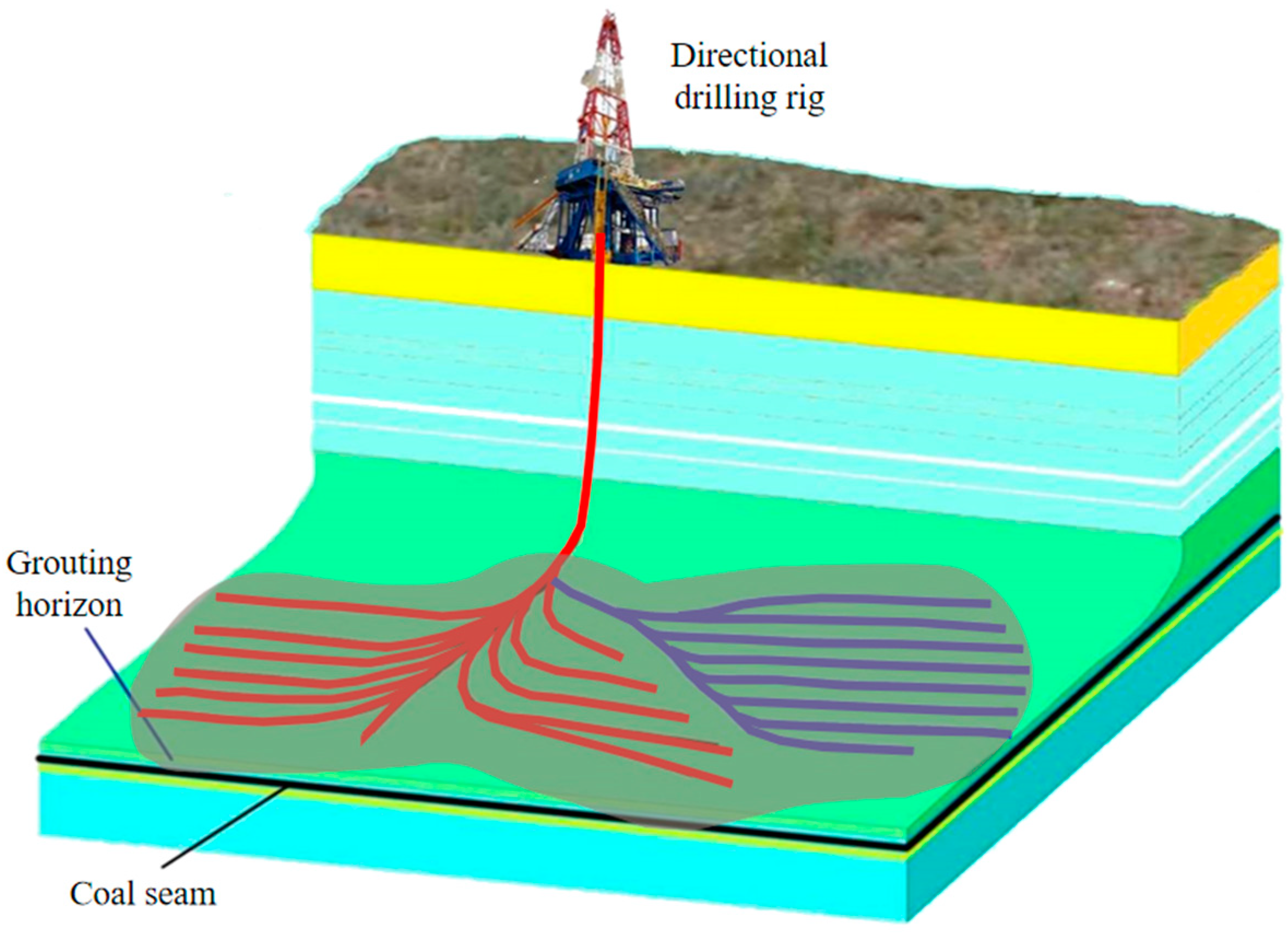
Figure 1. Schematic diagram of ground horizontal hole regional grouting governance.
Water 16 02814 g001
Figure 2. Curves of different rheological models.
Water 16 02814 g002
Figure 3. Radial diffusion of cement slurry in planar fracture.
Water 16 02814 g003
Figure 4. Geometric model of single-fracture grouting diffusion.
Water 16 02814 g004
Figure 5. Variation curve of grouting rate over time.
Water 16 02814 g005
Figure 6. Key parameter–time relationships under different grouting rates.
Water 16 02814 g006
Figure 7. Grouting rate–time variation curve.
Water 16 02814 g007
Figure 8. Grouting parameter–time variation curve.
Water 16 02814 g008
Figure 9. Slurry diffusion morphology.
Water 16 02814 g009
Figure 10. Comparison of slurry diffusion distance.
Water 16 02814 g010
Figure 11. Slurry diffusion distance–time variation curve.
Water 16 02814 g011
Figure 12. Grouting pressure–time variation curve.
Water 16 02814 g012
Table 1. Variable-rate grouting slurry diffusion calculation table.
ParameterScheme 1Scheme 2Scheme 3
Gap width, 2b0.005 m0.005 m0.005 m
Radius of grouting hole, r00.02 m0.02 m0.02 m
Grouting rate, q7.5 L/min15 L/min30 L/min
Total grouting time, T1000 s1000 s1000 s
w/c1.01.01.0
Hydrostatic pressure, pw0 Pa0 Pa0 Pa
Table 2. Parameters for staged decreasing-rate fracture grouting.
Type of GroutingGrouting StageGrouting Rate, q/(L/min)Grouting Time, T/s
Constant speed/8.76600
Staged decreasing ratestage 115200
stage 27.5200
stage 33.75200
Note: Fracture width b = 0.0025 m, grouting pipe radius r0 = 0.01 m, grouting material is cement slurry with a time-varying viscosity function μ(t) = 0.001137e0.0138t.
Disclaimer/Publisher’s Note: The statements, opinions and data contained in all publications are solely those of the individual author(s) and contributor(s) and not of MDPI and/or the editor(s). MDPI and/or the editor(s) disclaim responsibility for any injury to people or property resulting from any ideas, methods, instructions or products referred to in the content.