Article

The Sandwich-Structured PVA/PA/PVA Tri-Layer Nanofiltration Membrane with High Performance for Desalination and Pollutant Removal

by
Weibin Cai
1,*,
Yuzhe Wang
1,
Yuannan Li
1,
Hong Ye
2,3,*,
Fuyuan Xiao
1,
Lei Wang
1 and
Hengjun Gai
1
1
School of Chemical and Environmental Engineering, China University of Mining and Technology, Beijing 100083, China
2
School of Light Industry Science and Engineering, Beijing Technology and Business University, Beijing 100048, China
3
Key Laboratory of Geriatric Nutrition and Health, Beijing Technology and Business University, Ministry of Education, Beijing 100048, China
*
Authors to whom correspondence should be addressed.
Water 2024, 16(19), 2752; https://doi.org/10.3390/w16192752
Submission received: 29 August 2024 / Revised: 25 September 2024 / Accepted: 25 September 2024 / Published: 27 September 2024

Abstract

:
Nanofiltration (NF) has become a widely used technology in water treatment due to its environmental friendliness, energy efficiency, cost-effectiveness, and operational simplicity. However, polyamide (PA) NF membranes still face challenges, including low permeate flux, limited resistance to organic pollutants, and inadequate resilience to residual chlorine. To address these issues, this study developed a thin-film composite (TFC) NF membrane featuring a separation layer of sandwich structure. Initially, a single separation layer of polyvinyl alcohol (PVA) NF membrane was prepared, followed by the fabrication of a PA layer on its surface, and ultimately, a second PVA layer was constructed on the PA layer. The experimental results show that the PVA/PA/PVA sandwich structure TFC exhibits high permeability to pure water and robust resistance to both pollution and residual chlorine. The PVA-0.20/PA/PVA-0.20 TFC, prepared with a 0.20%w/v PVA solution, achieved a pure water flux of up to 22.05 L m−2 h−1 bar−1 (LMH/bar), which was 2.92 times higher than that of the control TFC membrane. Additionally, it demonstrated a salt rejection rate exceeding 96% for Na2SO4 and over 99% for Congo Red (CR) and Victoria Blue B (VB). In comparison with the control TFC membrane, the PVA-0.20/PA/PVA-0.20 membrane exhibited significantly enhanced resistance to pollution. Following immersion in a 1000 ppm NaClO solution for 4 h, the rejection rate of the control TFC membrane decreased markedly and that of the PVA-0.20/PA/PVA-0.20 membrane decreased marginally, indicating excellent resistance to residual chlorine. Due to the robust overall performance of the PVA/PA/PVA membrane, it holds potential advantages for application in treating reclaimed water or slightly polluted water.

1. Introduction

In recent years, with the growth of population and industrial development, climate change and pollution have become increasingly serious, leading to a particularly prominent water shortage problem in developing countries [1,2,3,4]. Currently, approximately 30% of the global population is experiencing inadequate access to safe drinking water, and it is projected that this figure will increase to 66% by 2025 [5,6]. Water contamination has had a significant impact on the daily lives of individuals, as the majority of identified heavy metals present substantial health hazards [7,8]. Common water treatment technologies include chemical coagulation [9], gravity separation [10], and filtration [11]. However, these methods are plagued by challenges such as intricate operational procedures, elevated operational expenditures, emissions of secondary pollutants, and suboptimal treatment efficacy [12,13]. Due to its environmentally friendly properties, high efficiency, cost-effectiveness, and ease of operation, NF has been widely utilized in the field of water treatment, encompassing seawater desalination, drinking water purification, softening water, wastewater treatment, and recycled water utilization [14,15,16,17,18].
At present, the predominant type of NF membranes in commercial use is composite membrane. The composite membrane consists of a porous base membrane and an ultra-thin separation layer, wherein the support layer and separation layer are typically fabricated from distinct materials [19,20,21]. Conventional NF membranes typically feature a separation layer composed of PA, which is prepared through interfacial polymerization (IP) using amine monomers and carbonyl chloride monomers on a porous support layer [22,23]. The flux of nanofiltration membrane prepared using the conventional IP method, however, is relatively low. For instance, the widely utilized NF90 NF membrane exhibits a flux rate of merely 7–8 LMH/bar [24]. One of the primary factors is that the thickness of the PA separation layer, prepared by the conventional IP method, results in increased resistance to permeation and diminished permeate flux [25]. In addition, the hydrophilicity of PA is insufficient, which also has an adverse effect on water penetration [26].
To tackle this issue, researchers have endeavored to enhance permeability by selecting suitable monomers. Yuan et al. [27] synthesized 1,2,3,4-cyclobutane tetracarboxylic acid chloride (BTC) as a novel oil-phase monomer. In comparison with the commonly utilized trimesoyl chloride (TMC), BTC exhibits a smaller molecular volume, enabling the molecules situated at the interface to react with more water-phase monomers and form a denser PA NF membrane. The resulting separation layer thickness measures only 15 nm. This ultra-thin separation layer structure has significantly enhanced the flux and rejection performance of the NF membrane. Li et al. [28] chose 3,3′,5,5′-biphenyl tetra acyl chloride (mm-BTEC) as the organic phase monomer and piperazine (PIP) as the initiator for the fabrication of NF membranes. Due to the higher carboxyl content of mm-BTEC, the resulting separation layer exhibits enhanced hydrophilicity, leading to improved NF flux. However, the mm-BTE molecule possesses a larger volume, resulting in slightly increased pore sizes within the separation layer, thereby leading to a reduction in the separation efficiency of the NF membrane. In addition to selecting the appropriate reactive monomer, surface modification represents a straightforward approach for enhancing membrane permeability. Huang et al. [29] modified the surface of the PA membrane with betaine, resulting in a distinctive leaf-like structure that increased the permeable area and enhanced hydrophilicity. This modification led to a 1.2-fold increase in permeability compared to the unmodified membrane while maintaining excellent rejection of Na2SO4. In addition, when the surface of the porous support layer contains large holes, it will lead to pore intrusion and the defects of the separation layer, which is also one of the reasons for the small permeate flux [30,31,32]. Fang et al. [33] introduced a novel covalent organic frameworks (COFs) material on the support layer to mitigate the permeation of the PA layer, resulting in a double-layered modified nanocomposite membrane with a pure water permeate flux of 27.3 LMH/bar, which is three times that of the unmodified membrane, and the Na2SO4 rejection rate of 98.40%. Bai et al. [34] fabricated a cellulose nanocrystal (CNC) intermediate layer on the support layer using a two-step method, followed by polymerization of PA on the intermediate layer and subsequent surface modification with polydopamine (PDA). After undergoing this two-step modification process, the NF membrane exhibits a rejection rate of 98.2% for Na2SO4, with a permeate flux of 23.1 LMH/bar.
In recent years, PVA has been widely employed in the fabrication of NF membranes due to its abundant hydroxyl groups and excellent separation performance. Zhang et al. [35] utilized PVA and modified graphene oxide (GO) as the intermediate layer, followed by cross-linking with glutaraldehyde (GA) for post-cross-linking. Subsequently, they fabricated a NF membrane with a PA layer thickness of merely 15 nm via IP, leading to a significant enhancement in the separation performance of the NF membrane. Under optimized conditions, the membrane achieved an impressive salt rejection rate of 99.70% for Na2SO4. Zhu et al. [36] fabricated a NF membrane featuring a PA layer thickness of merely 9.6 nm, utilizing polyether sulfone (PES) as the support layer and PVA as the intermediate layer. The NF membrane incorporating a PVA intermediate layer exhibited a high permeate flux of 31.4 LMH/bar and an impressive rejection rate of 99.40% for Na2SO4. Januario et al. [37] reported a remarkable retention rate exceeding 99.9% for dyes utilizing a microfiltration (MF)/PVA60+GO1+PVA30 membrane, which was constructed through layer-by-layer (LBL) self-assembly on the surface of the MF membrane with PVA, GO, and PVA applied sequentially. The flux recovery rate was approximately 80%, while the retention rate remained above 94% even after multiple cycles of use.
To enhance the permeate flux of the NF membrane, in this study, we developed a novel preparation method for NF membranes with PVA/PA/PVA sandwich structure separation layers. First, a PVA intermediate layer is applied to the surface of the polysulfone (PS) ultrafiltration membrane. This layer not only exhibits certain separation performance but also provides a dense support surface, which can greatly inhibit the defects of the PA separation layer. Subsequently, a PA separation layer was prepared on the surface of the PVA layer, and the separation performance of the composite membrane was significantly improved by the PA layer. Finally, a secondary PVA layer is applied to the PA surface, leveraging PVA’s excellent hydrophilicity and specific separation properties to further enhance membrane performance. Moreover, the PVA layer can bolster the membrane’s resistance to pollution and tolerance to residual chlorine. To further improve the permeability of the composite membrane, the PA layer was synthesized via IP using PIP and triethanolamine (TEOA) as co-solvents with TMC to augment the hydrophilicity of the PA layer [38]. The effect of the concentration of PVA casting solution on the separation performance of the composite membrane was studied, and the membranes’ permeation performance, rejection performance, anti-pollution performance, and resistance to residual chlorine were comprehensively investigated.

2. Materials and Methods

2.1. Materials

The flat-sheet nonwoven-reinforced PS ultrafiltration membrane was procured from AnD Membrane Separation Technology Engineering Co., Ltd. (Beijing, China). PIP (99.5% purity) was procured from Beijing Bailingwei Technology Co., Ltd. (Beijing, China). N-hexane (98% purity) was procured from Tianjin Kangkede Technology Co., Ltd. (Tianjin, China). TMC (98% purity), PVA (99.5% purity), anhydrous ethanol (99.9% purity), sulfuric acid (H2SO4, 99.8% purity), sodium dodecyl sulfate (SDS, 99.7% purity), sodium hypochlorite (NaClO, 99.7% purity), and CR (98% purity) were procured from Shanghai McLin Biochemical Technology Co., Ltd. (Shanghai, China). Anhydrous sodium sulfate (Na2SO4, 99.7% purity), sodium chloride (NaCl, 99.7% purity), magnesium sulfate (MgSO4, 99.7% purity), and sodium alginate (SA, 99.5% purity) were procured from Guoyao Group Chemical Reagents Co., Ltd. (Shanghai, China). Magnesium chloride (MgCl2, 99.7% purity), trimellitic anhydride (TMA, 98% purity), and VB (80% purity) were procured from Aladdin Reagents Co., Ltd. (Shanghai, China). TEOA (97% purity) was procured from Xilong Chemical Industry Co., Ltd. (Shantou, China). Barium chloride (BaCl2, 97% purity) was procured from Beijing Mairaida Technology Co., Ltd. (Beijing, China). Neutral red (NR) was procured from Shanghai Yuanye Biological Technology Co., Ltd. (Shanghai, China). Rhodamine B (Rh B, 95% purity) was procured from Beijing Yinghai Fine Chemical Factory (Beijing, China). Eriochrome black T (EBT, 90% purity) was procured from Modern East Science and Technology Development Co., Ltd. (Beijing, China). Bovine serum albumin (BSA, 98% purity) was obtained from Beijing Huawi Ruike Chemical Technology Co., Ltd. (Beijing, China).

2.2. Membrane Preparation

2.2.1. Preparation of PVA Interlayer

The PVA interlayer was fabricated using a gradient cross-linking approach [39]. Initially, the PS ultrafiltration membrane was securely positioned between a glass plate and a silicone rubber spacer. Subsequently, the cross-linking solution, comprising a blend of ethanol and deionized water in an equal volume ratio (1:1), containing 0.2%w/v TMA, 0.5%w/v SDS, and 0.05%w/v H2SO4, was applied onto the surface of the ultrafiltration membrane. After allowing it to stand for 10 min to remove excess solution, the sample was subjected to electric hot-air drying at 35 °C for 8 min. After undergoing heat treatment, the PVA solution at concentrations of 0.05%w/v, 0.10%w/v, 0.15%w/v, 0.20%w/v, and 0.25%w/v was uniformly applied onto the membrane surface, respectively, followed by removal of excess solution after a standing period of 5 min. Subsequently, membranes were returned to an electric hot-air drying oven at 80 °C for 10 min to yield a support membrane with a PVA intermediate layer. The membranes mentioned above were designated as PVA-0.05, PVA-0.10, PVA-0.15, PVA-0.20, and PVA-0.25 based on the varying concentrations of PVA.

2.2.2. Preparation of PA/PVA Membrane

Prepare a 0.05%w/v PIP solution and a 0.95%w/v TEOA solution in water, apply them onto the membrane surface with an intermediate layer of PVA, allow to stand for 2 min, remove excess liquid, and subject to heat treatment at 35 °C for 8 min. After the removal process, a 0.2%w/v TMC hexane solution is uniformly applied onto the membrane surface and allowed to stand for 30 s before promptly draining off the excess liquid and subsequently rinsing the membrane with hexane multiple times. The prepared membrane underwent heat treatment at 60 °C for 15 min to yield the PA/PVA NF membrane. The membranes mentioned above were designated as PA/PVA-0.05, PA/PVA-0.10, PA/PVA-0.15, PA/PVA-0.20, and PA/PVA-0.25.

2.2.3. Preparation of PVA/PA/PVA Membrane

In accordance with the steps detailed in Section 2.2.1., a second PVA separation layer was fabricated on the surface of the PA/PVA membranes; the concentration of PVA solution used was the same as that used in the preparation of the intermediate PVA layer. The membranes prepared were designated as PVA-0.15/PA/PVA-0.15, PVA-0.20/PA/PVA-0.20, and PVA-0.25/PA/PVA-0.25 based on the concentration of PVA used in the preparation process. Figure 1 illustrates the procedure for fabricating the PVA/PA/PVA sandwich structure NF membrane.

2.2.4. Preparation of Control TFC Membrane

A control TFC membrane was fabricated using conventional IP. Prepare a 1%w/v PIP aqueous solution, apply it to the surface of the PS substrate, and allow it to stand for 2 min. Subsequently, remove the excess liquid and uniformly apply the 0.2%w/v TMC hexane solution onto the membrane surface, allowing it to sit for 30 s before promptly removing any surplus liquid and repeatedly rinsing with n-hexane. The prepared membrane was subsequently subjected to a heat treatment at 60 °C for 15 min to yield the control TFC membrane.

2.3. Characterization of Membrane Physicochemical Properties

Attenuated total reflection Fourier-transform infrared (ATR-FTIR, Nicolet 6700, Thermo Fisher Scientific, Waltham, MA, USA) and X-ray photoelectron spectroscopy (XPS, Escalab 250Xi, Thermo Fisher Scientific) were employed for the analysis of the surface chemical structure and composition of the membrane. Membrane morphologies were characterized by scanning electron microscopy (SEM, SU8600, Hitachi, Tokyo, Japan). To determine the surface roughness of the membranes, atomic force microscopy (AFM, Dimension Icon, Bruker, Billerica, MA, USA) in tapping mode was used. The water contact angle of membrane surfaces was measured using a contact angle goniometer (WCA, OCAH 200, Data-physics, Filderstadt, Germany).

2.4. Membrane Performance Testing

2.4.1. Permeability and Rejection Performance of the Membranes

This study employed a crossflow apparatus to evaluate the separation and permeability characteristics of the membrane [40]. In order to minimize experimental error, each membrane was measured three times, and the average was calculated. Prior to the test, the membrane was rinsed with ultrapure water and operated at 0.8 MPa for 30 min to stabilize its performance. Subsequently, under a pressure of 0.8 MPa, the permeate passing through the membrane per unit time was collected, and the filtration flux (J) of the NF membrane was determined using Formula (1) as follows:
J = m ρ S t
where J denotes the filtration rate (LMH), S denotes the effective membrane area (m2), Δt is the duration for collecting the filtrate (h), Δm(g) is the increase in filtrate mass during Δt, and ρ stands for the density of the filtrate (approximately 1 g/mL when the salt concentration is low).
The permeate flux refers to the volume of liquid that permeates through a unit area of membrane under unit pressure in a given time period. The relationship between permeate flux and filtration flux is depicted in Equation (2) as follows:
F l u x = J P
where ∆P denotes the test pressure (bar), while the permeate flux is expressed in units of LMH/bar.
The electrical conductivity of the feed liquid and the filtrate was measured using a conductivity meter [35]. As the electrical conductivity of a dilute, strong electrolyte solution is directly proportional to its concentration, the ratio of conductivities can be approximated by the concentration ratio. The feed liquid was maintained at a concentration of 0.5 g/L, and the test was conducted at an ambient temperature. The equation for calculating the rejection rate is presented in Equation (3) as follows:
R = 1 C P C F × 100 %
where R denotes the rejection rate (%), CP denotes the concentration of the filtrate, and CF denotes the concentration of the feed liquid.
Meanwhile, NR, Rh B, VB, EBT, and CR (0.1 g/L) were selected to evaluate the dye retention performance of the composite membrane. The operating pressure is 0.8 MPa, and the concentrations of dye in the feed liquid and permeate are individually measured, and the dye rejection rate of the composite membrane is calculated using Equation (3). The dye concentration is determined utilizing a spectrophotometric method [41].
And static adsorption tests were carried out on the dye [42]. For the static adsorption tests, the membrane samples (50.24 cm2) were immersed in dye solutions (0.1 g/L, Ci) for 2 h. Equilibrium concentrations of dye (Ce) were measured by UV-vis spectrophotometry. The adsorbed mass of dye per unit area of membrane (Q, mg/cm2) was calculated using Equation (4) as follows:
Q = C i C e V A
where A is the effective membrane area (cm2), V is the volume of dye solution (mL), and Ci and Ce are the initial and equilibrium dye concentrations (g/L), respectively.

2.4.2. Antifouling Performance

The anti-pollution performance test was carried out at 25 °C and 0.8 MPa using BSA and SA solution (0.5g/L). The test was conducted for 1.5 cycles with the following cycle process: deionized water solution was used as the feed solution to obtain the filtration flux J0 during the initial 3 h. Then, the BSA/SA solution was applied for 6 h, during which the filtration flux Jt was measured at 0.5 h intervals. And subsequently replaced with deionized water to rinse the membrane for 3 h, and the measured filtration flux was denoted as Jr. The obtained time-dependent normalized flux (Jt/J0) profiles were used to investigate the fouling behaviors of the tested membranes. The flux recovery ratio (FRR, %) and flux decline ratio (FDR, %) were determined through the following Equations (5) and (6), respectively:
FRR = J t J 0 × 100 %
FDR = J 0 J r J 0 × 100 %
The higher FRR value indicates the higher cleaning efficiency, while the lower FDR value means the better antifouling property.

2.4.3. Chlorine Resistance Test

The membrane was dipped into a 1.0 g/L NaClO solution (pH = 4) for 10 h. The performance of the membrane was measured every 2 h. In order to ensure the concentration of NaClO in the solution remained unchanged, we replaced the soaked solution of NaClO every 5 h [43,44].

3. Results and Discussion

3.1. Surface Chemistry

Figure 2 depicts the infrared spectra of PVA-0.20, PA/PVA-0.20, and PVA-0.20/PA/PVA-0.20 membranes. The absorption peaks at 1487 cm−1 correspond to the C-C bond, while the peak at 1238 cm−1 is assigned to the C-O-C bond, both of which are characteristic peaks of the PS membrane [45]. The intensity of the characteristic peak at 1710 cm−1 in the PA/PVA-0.20 membrane increased, attributed to the ester formed by the reaction between TMC and TEOA. Additionally, a new characteristic peak is observed at 1040 cm−1 due to the C-N bond in PIP and TEOA. The increase in intensity of the peak at 1710 cm−1 and the observation of a new peak at 1040 cm−1 were attributed to the formation of the PA layer [46,47]. The characteristic peak intensity at 1710 cm−1 in the PVA-0.20/PA/PVA-0.20 membrane is further enhanced due to the cross-linking of the PVA and TMA onto the surface of the PA layer, leading to increased production of ester. Moreover, the strength of the O-H stretching at 3200~3600 cm−1 for the PA/PVA-0.20 membrane is much greater than that of the PVA-0.20 and PVA-0.20/PA/PVA-0.20 membranes, due to the abundant hydroxyl groups in TEOA. The utilization of TEOA as a co-solvent effectively enhances the hydrophilicity of the PA layer [48].
To further validate the elemental composition of the membranes’ surface, XPS analysis was performed. The peaks at 532 eV, 401 eV, and 285 eV correspond to oxygen (O), nitrogen (N), and carbon (C) elements, respectively [48]. The XPS elemental spectrum in Figure 3a reveals an increased intensity of the N1s peak on the surface of PA/PVA-0.20, attributable to the presence of C-N bonds within the amide bonds in the PA layer. The N1s peak intensity on the surface of the PVA-0.20/PA/PVA-0.20 membrane decreased, while the O1s peak intensity increased. This result is due to the introduction of more hydroxyl groups by PVA, thereby enhancing the membrane’s hydrophilicity [49]. In Figure 3c, a lower proportion of C-O-C bonds resulting from the cross-linking of PVA and TMA is observed compared to Figure 3b, while an increase in the proportion of C=O bonds is noted. This is attributed to the C=O bonds in PVA-0.20 primarily originating from the unreacted carboxyl (-COOH) group on TMA, whereas the C=O bonds in PA/PVA-0.20 arise from the isocyanate group (N-C=O) within the amide group and the ester formed through the reaction between TEOA and the anhydride [50]. A new characteristic peak at 286eV is observed, corresponding to the carbon atoms bonded by amide linkage, unreacted amine, and the C-N bond in the TEOA molecular chain. Figure 3d illustrates an increase in the proportion of C-O-C bonds due to the presence of a PVA layer on the surface of the PA layer, accompanied by a decrease in the proportion of C=O and C-N bonds. A relatively small N1s peak was observed on the surface of the PVA-0.20 membrane, and the trace amount of nitrogen detected on the surface of the PVA-0.20 membrane may be attributed to the adsorption of atmospheric pollutants onto the sample surface [51].

3.2. Morphologies

Figure 4 is the surface and cross-section morphology of PS substrate and various composite membranes by SEM imaging, as well as the AFM images of the membrane surface. Figure 4a,e shows the surface and cross-section SEM images of the PS substrate, revealing its smooth and flat surface characteristics. After the application of the PVA layer, as depicted in Figure 4b, the floc-like particulate architecture of the PVA gradient cross-linked layer is distinctly observable. Table 1 shows the surface roughness of the membranes. In comparison to the PS substrate, a slight increase in surface roughness is observed for PVA-0.20, with Ra rising from 3.5 nm to 11.3 nm. Figure 4c depicts the membrane surface following the IP, showing a distinct ridged structure characteristic of the PA layer [52] and an elevated surface roughness Ra of 16.5 nm. Figure 4d is the surface of the membrane subsequent to the application of a PVA layer onto the PA layer, wherein we once again discern the floc-like particulate architecture characteristic of the PVA layer. Following the formation of the second PVA separation layer, it partially filled the ridges on the surface of the PA layer, resulting in a reduction in roughness to some extent [48], with Ra decreasing to 8.8 nm. As depicted in Figure 4f–h, the separation layer thicknesses of PVA-0.20, PA/PVA-0.20, and PVA-0.20/PA/PVA-0.20 membranes measure 62 nm, 111 nm, and 186 nm, respectively.

3.3. Hydrophilicity

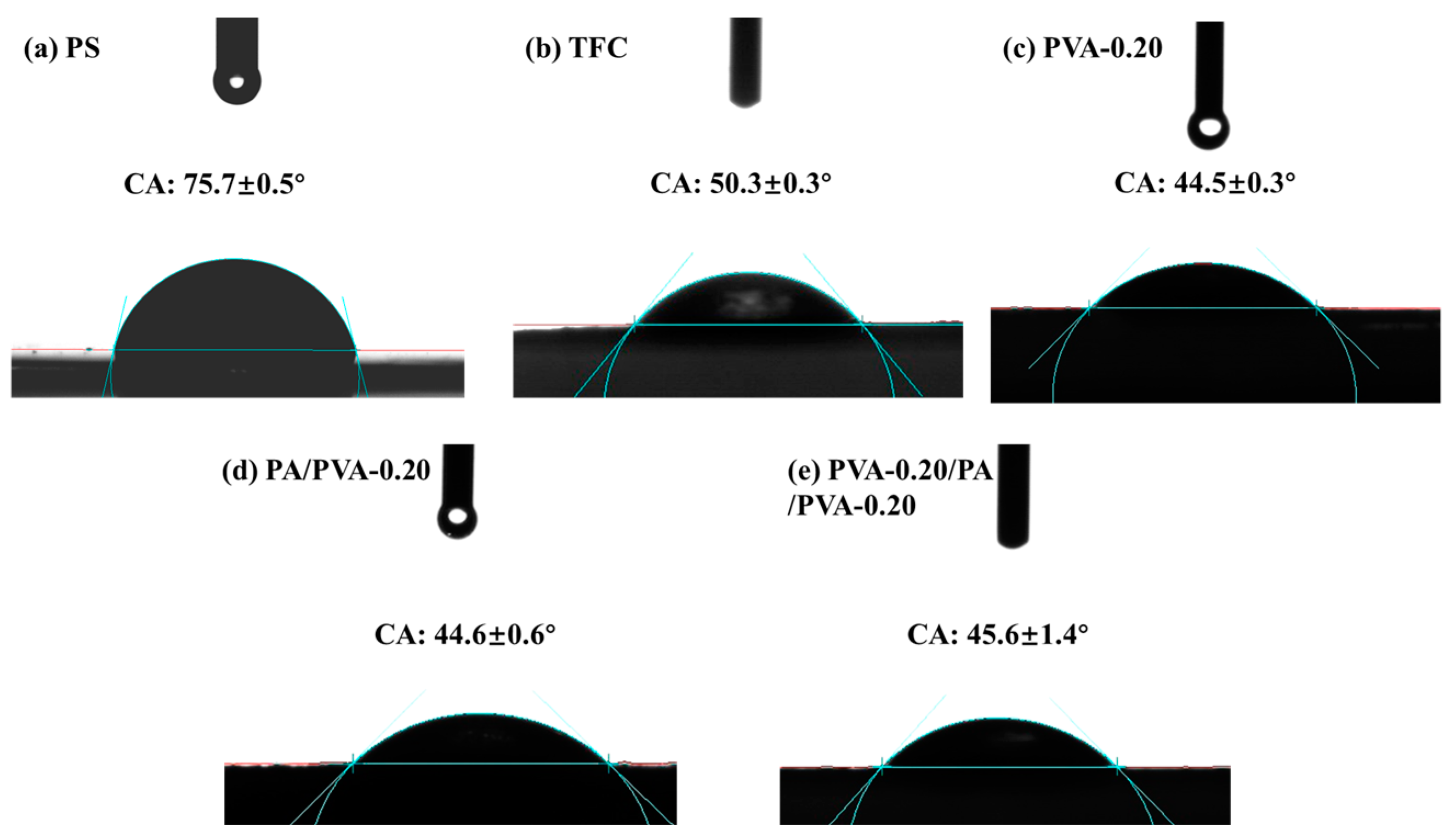
Static water contact angle tests were performed to investigate the hydrophilicity of the membranes, as shown in Figure 5. The water contact angle of the PS substrate is 75.7°, while for the control TFC membrane, PVA-0.20, PA/PVA-0.20, and PVA-0.20/PA/PVA-0.20 membrane are 50.3°, 44.5°, 44.6°, and 45.6°, respectively. Due to the abundant hydroxyl group in both PVA and TEOA, they exhibit strong hydrophilic properties.

3.4. Permeability and Salt Rejection

A PVA single-layer NF membrane was fabricated on a PS substrate, and the impact of varying PVA concentrations on the permeate flux and rejection rates of Na2SO4 and NaCl was investigated. The results are depicted in Figure 6. It is evident that with the increase in PVA concentration from 0.05% to 0.25%, there is a gradual decrease in the pure water flux of the membrane, accompanied by a corresponding gradual increase in the rejection rates of Na2SO4 and NaCl. The increase in PVA concentration leads to an increase in the thickness of the PVA layer, resulting in elevated permeability resistance and salt retention. However, the overall salt rejection rate for this series of membranes is relatively low. Due to the trade-off effect, it is hard to identify a single or dual membrane with consistently excellent overall performance. Additionally, determining superior performance when combined with the PA layer presents further complexity. Consequently, a series of dual separation layer NF membranes, named PA/PVA-0.05, PA/PVA-0.10, PA/PVA-0.15, PA/PVA-0.20, and PA/PVA-0.25, were fabricated via interfacial polymerization on PVA-based single-layer membranes ranging from PVA-0.05 to PVA-0.25 for comparison.
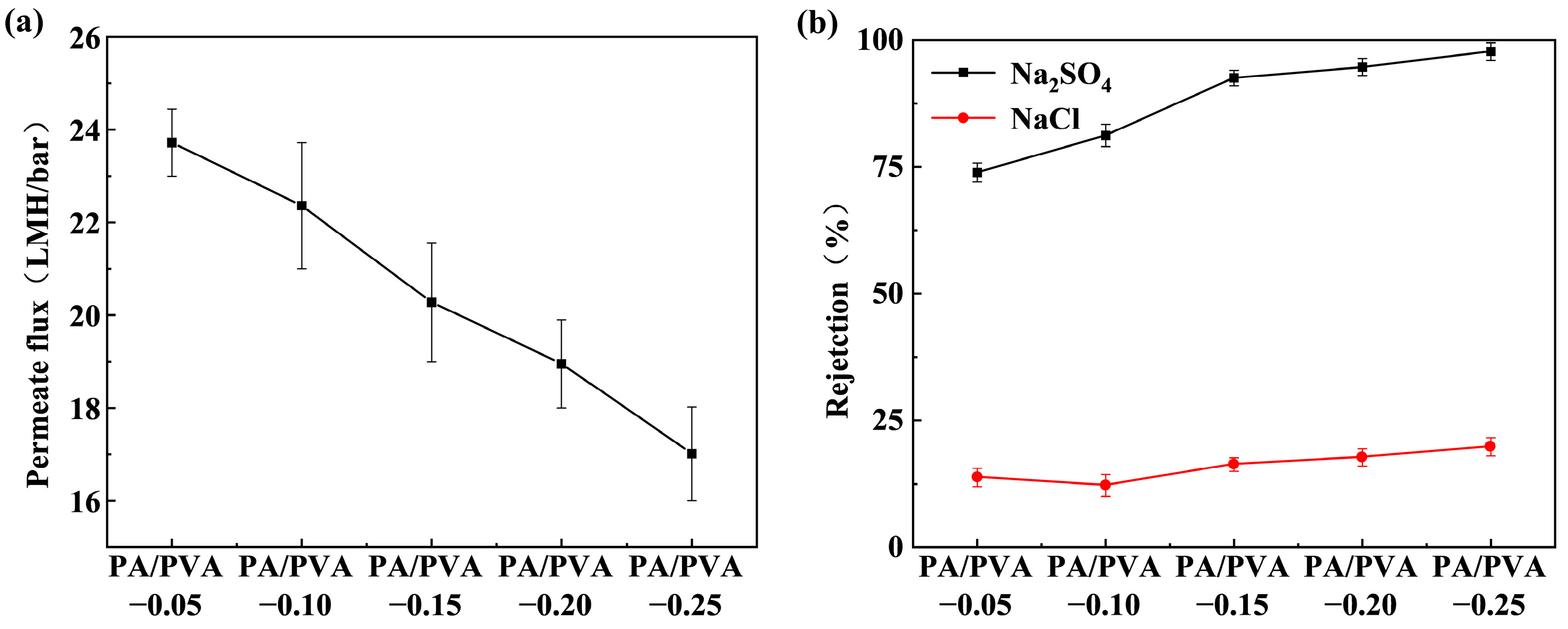
Figure 7 illustrates the NF performance of the PA/PVA series composite membrane. It is evident that with the increase in bottom PVA concentration from 0.05% to 0.25%, the flux of the PA/PVA series membranes decreases from 23.72 LMH/bar to 17.01 LMH/bar, while the rejection rate of Na2SO4 increases from 73.88% to 97.75%, and the rejection rate of NaCl ranges between 10% and 20%. This is attributed to the PA layer, which increases the permeability resistance and enhances the rejection rate of Na2SO4. Although the permeate flux of the PA/PVA membranes has slightly decreased compared to the PVA membrane, the rejection rate of Na2SO4 has increased by approximately 10%, while the rejection rate of NaCl has decreased by about 10%. The performance in separating monovalent and divalent salts has been enhanced. Due to the superior comprehensive separation performance, PA/PVA-0.15, PA/PVA-0.20, and PA/PVA-0.25 were chosen for further investigation.
PVA layers were once again fabricated on the surfaces of PA/PVA-0.15, PA/PVA-0.20, and PA/PVA-0.25 to fabricate a series of sandwich structure NF membranes: PVA-0.15/PA/PVA-0.15, PVA-0.20/PA/PVA-0.20, and PVA-0.25/PA/PVA-0.25. The permeate flux and rejection rate are illustrated in Figure 8.
As can be seen from Figure 8, with the increase in PVA concentration from 0.15% to 0.25%, the permeate flux of the PVA/PA/PVA membranes gradually decreases from 26.27 LMH/bar to 19.33 LMH/bar. The rejection rate of Na2SO4 shows a slight increase, reaching approximately 96.62% at the highest concentration, attributed to the progressive thickening of the PVA separation layer. Compared with the PA/PVA membranes, the PVA/PA/PVA membranes exhibit enhanced separation performance, with a 14–20% increase in permeate flux and a slight improvement in the rejection rate of Na2SO4. PVA itself exhibits strong hydrophilicity, and the addition of SDS to the casting solution further enhances the hydrophilicity of the PVA layer. Simultaneously, PVA layer undergoes gradient cross-linking, resulting in a loose upper layer and a dense lower layer in the PVA layer. This gradient cross-linked structure reduces the resistance of water when entering the PVA layer. All these attributes collectively contribute to augmenting the water’s permeability. Since the permeability flux increases after the PVA separation layer is coated on the PA surface, it can be inferred that the resistance of water entering the PA separation layer from the feed solution is larger and greater than the resistance of water entering the PVA layer from the feed solution and continuing to penetrate the PVA layer and entering the PA layer. Zhao [53] fabricated NF membranes via LBL assembly of hydrophobic TpTGCl and hydrophilic TpPa-SO3H. The results indicate that the membrane featuring a hydrophilic surface layer of TpPa-SO3H exhibits higher permeability compared to the membrane with a hydrophobic surface layer of TpTGCl.
Overall, the performance of PVA-0.20/PA/PVA-0.20 demonstrates superiority, exhibiting a pure water flux of up to 22.05 LMH/bar, a salt rejection rate exceeding 96% for Na2SO4, and a salt rejection rate below 20% for NaCl. It exhibits excellent separation performance for monovalent and divalent salts while maintaining high flux, and the simultaneous improvement in flux and rejection rate of PVA-0.20/PA/PVA-0.20 compared to PA/PVA-0.20 overcomes the “trade-off” effect.
Table 2 presents a separation performance comparison between the control TFC and the PVA-0.20/PA/PVA-0.20. It is apparent that compared with the control TFC, the PVA-0.20/PA/PVA-0.20 exhibited a significant increase in water flux while the retention rate of Na2SO4 experienced a slight decrease, and that of NaCl underwent a substantial decrease. This is attributed to the formation of the PA layer in the PVA/PA/PVA series membranes through the IP reaction between TMC and TEOA as the co-aqueous phase. The surface of TEOA is abundant in hydroxyl groups, which serve to enhance the hydrophilicity of the PA layer. Additionally, the presence of a grafted PVA layer on top of the PA layer further diminishes water permeability.
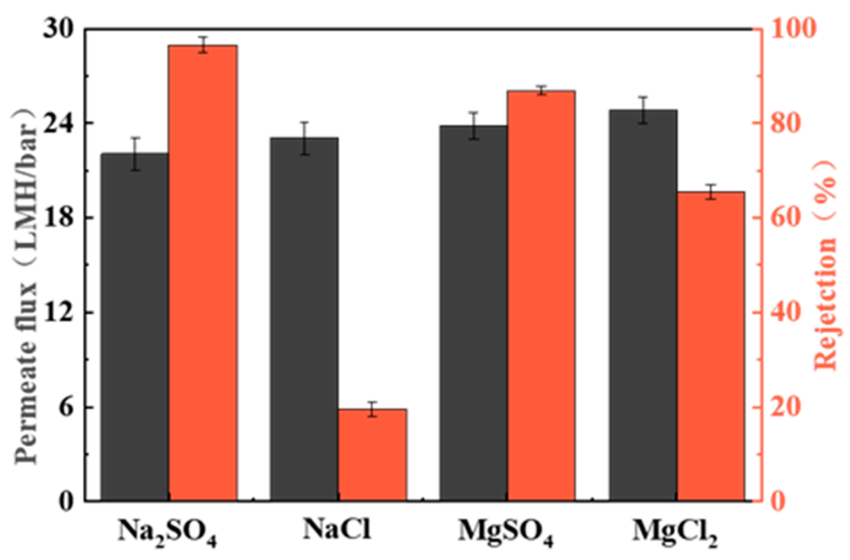
Figure 9 illustrates the separation performance of the PVA-0.20/PA/PVA-0.20 membrane for four inorganic salts (Na2SO4, MgSO4, MgCl2, and NaCl) at a 0.5 g/L solution, where a test pressure of 0.8 MPa and room temperature were applied. The PVA-0.20/PA/PVA-0.20 membrane exhibits a rejection rate of 96.57% for Na2SO4, 86.52% for MgSO4, and 65.53% for MgCl2, while demonstrating a rejection rate of less than 20% for NaCl. The sequence of rejection rates for inorganic salts (R(Na2SO4) > R(MgSO4) > R(MgCl2) > R(NaCl)) aligns with the findings of Ren [54] and Guo [55], and this phenomenon may be caused by the negatively charged nature of the membrane surface [56].

3.5. Dye Removal by the Membranes

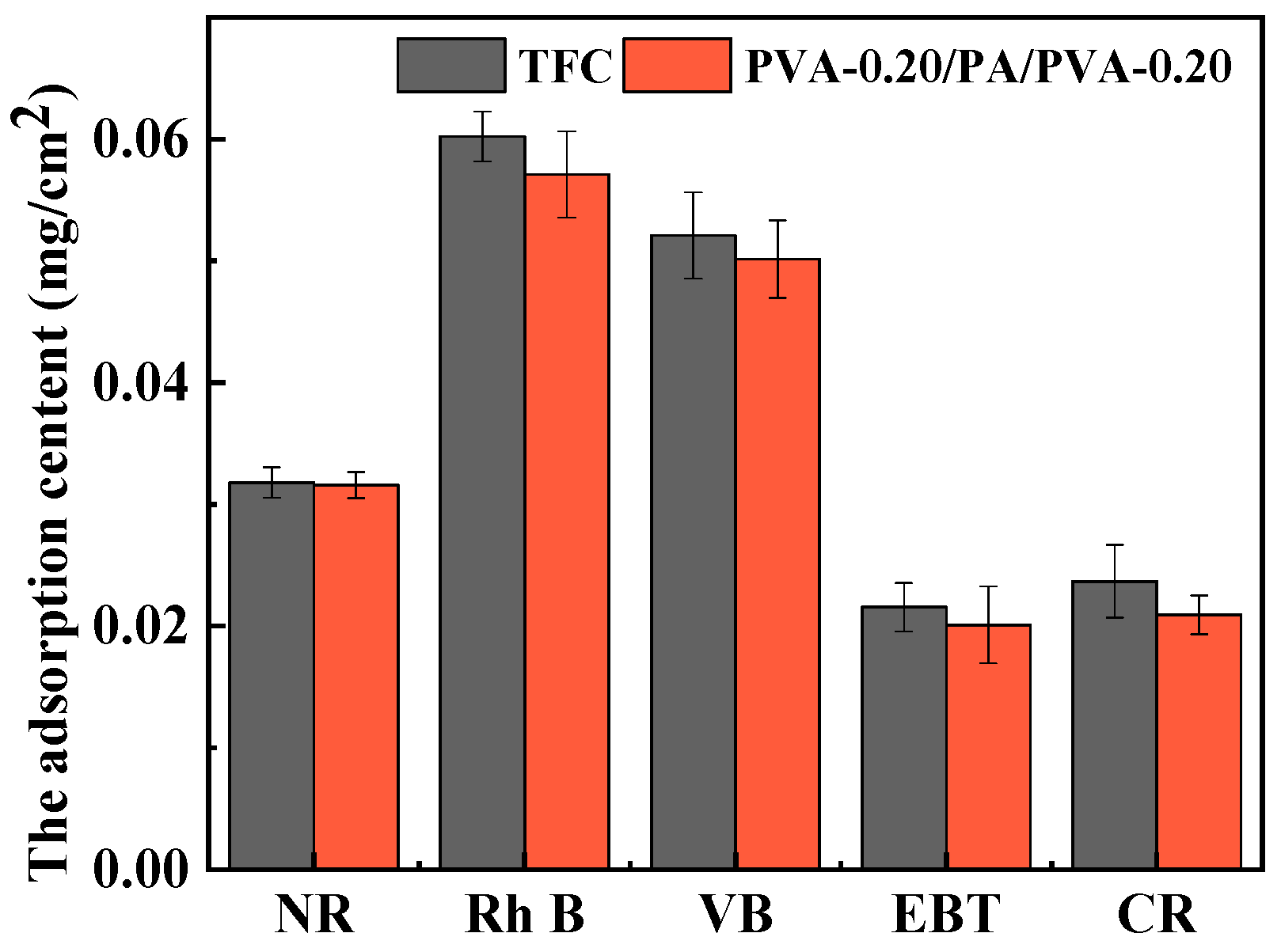
To assess the membrane’s retention performance for dyes, five dyes—NR, Rh B, VB, EBT, and CR—were further tested. The results were then compared with the control TFC membrane, as detailed in Table 3. The rejection rates of both membranes for positive dyes are in the order of R(VB) > R(Rh B) > R(NR), and for negative dyes, the retention order is R(CR) > R(EBT). Table 4 presents the molecular weight and charge characteristics of five dyes. In cases where dyes exhibit similar charge properties, the dominant factor for NF separation is the pore size sieving effect. The rejection rates of VB and CR both exceed 99.95%, indicating nearly complete removal, possibly attributed to the higher molecular weights of these dyes compared to the membranes’ retention molecular weight. It is also evident that R(EBT) > R(Rh B) attributed to the combined impact of size exclusion and Donnan exclusion. Both the control TFC and the PVA-0.20/PA/PVA-0.20 membrane exhibit negative surface charges due to the charge repulsion against EBT, which also carries negative charges. Henceforth, the smaller molecular weight of EBT results in a higher rejection rate compared to the larger molecular weight of Rh B [57,58]. The results of static adsorption experiments for five dyes on TFC and PVA-0.20/PA/PVA-0.20 membranes are shown in Figure 10. It can be observed that the adsorption capacity of the PVA-0.20/PA/PVA-0.20 membrane for the five dyes is all lower than that of the TFC membrane. The adsorption capacities of the two membranes for the positively charged NR, Rh B, and VB are far greater than those of the negatively charged EBT and CR. This phenomenon can be ascribed to the electrostatic repulsion between the negatively charged EBT and CR and the negative charges on the surfaces of the TFC membrane and the PVA-0.20/PA/PVA-0.20 membrane [42]. In comparison with the TFC membrane, the PVA-0.20/PA/PVA-0.20 membrane exhibits significantly enhanced permeability for five dyes while maintaining a high rejection rate.

3.6. Antifouling Properties

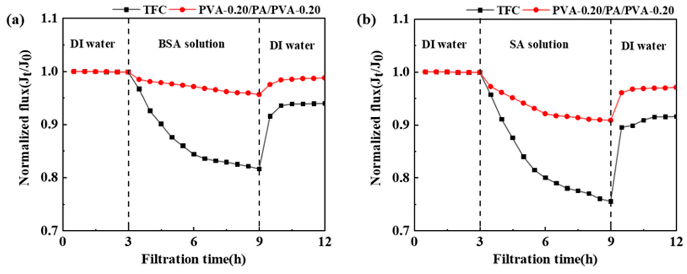
Membrane fouling is a prevalent issue encountered in the operation of NF membranes, leading to diminished separation performance and reduced service life, thereby impacting long-term operation. To assess the antifouling efficacy of the PVA-0.20/PA/PVA-0.20 membrane, two model pollutants, BSA and SA, were employed with the control TFC membrane for comparative analysis. Figure 11a,b depict the normalized water flux curves for BSA and SA contamination, respectively. It is evident that both contaminants exert a discernible influence on the normalized flux of the membranes. BSA is a protein-like model contaminant with substantial molecular volume. Its accumulation on the membrane surface can lead to the obstruction of membrane pores, resulting in decreased membrane permeability. SA, a model pollutant composed of polysaccharides, is inclined to form a substantial water gel layer on the membrane surface, resulting in a rapid decrease in the permeate flux. Compared with the TFC membrane, the anti-pollution performance of the PVA-0.20/PA/PVA-0.20 membrane has been significantly enhanced. After 0.5 h of exposure to pollution, the permeate flux of both the TFC membrane and the PVA-0.20/PA/PVA-0.20 membrane decreased; however, the decrease in permeate flux was significantly greater for the TFC membrane compared to that of the PVA-0.20/PA/PVA-0.20 membrane. After 6 h of exposure to BSA and SA contamination, the permeate flux of the PVA-0.20/PA/PVA-0.20 membrane only exhibited a marginal decrease of approximately 5% and 10%, respectively, whereas the TFC membrane experienced a reduction of around 20%. After a 3 h deionized water cleaning process, the permeate flux of the PVA-0.20/PA/PVA-0.20 membrane also recovered to over 95%, exhibiting significantly enhanced anti-pollution performance compared to the TFC membrane. Table 5 presents the FDR and FRR results for control TFC and PVA-0.20/PA/PVA-0.20 in the presence of BSA and SA contaminant solutions. For both solutions, the FDR of the PVA-0.20/PA/PVA-0.20 is lower than that of the control TFC, while the FRR is higher than that of the control TFC. This further underscores the superior antifouling performance and more significant cleaning efficiency of the PVA-0.20/PA/PVA-0.20. The membrane hydrophilicity is widely regarded as one of the most important factors for fouling control [59]. The antifouling performance of the control TFC and PVA-0.20/PA/PVA-0.20 aligns with the hydrophilic data shown in Figure 5. The PVA-0.20/PA/PVA-0.20 membrane exhibits a high density of -OH groups on its surface, contributing to its pronounced hydrophilicity and exceptional antifouling performance. Furthermore, reduced surface roughness also exerts a beneficial influence on the membranes’ resistance to pollution [60]. A PVA layer was grafted onto the surface of the PA layer, effectively filling in the surface ridges and reducing Ra to 8.8 nm. This enhancement contributes to the superior anti-pollution performance of the PVA-0.20/PA/PVA-0.20 membrane.

3.7. Chlorine Resistance

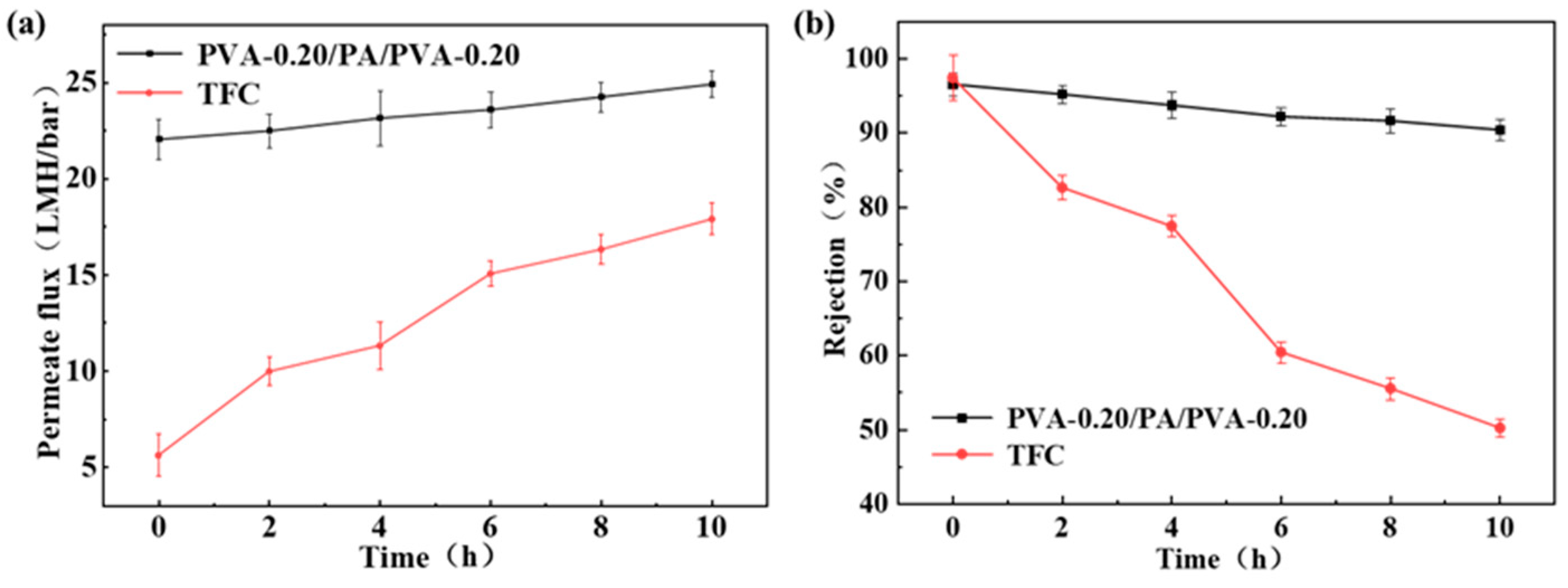
At room temperature, PVA-0.20/PA/PVA-0.20 and the control TFC membrane were immersed in a NaClO solution (pH = 4) for 0 to 10 h, and then the permeate flux and Na2SO4 rejection rate were assessed. The experimental results are depicted in Figure 12. In Figure 12a, the pure water permeate flux of the control TFC membrane exhibited a significant increase after the 4 h turning point. And the permeate flux of PVA-0.20/PA/PVA-0.20 showed a gradual increment within the 10 h. As depicted in Figure 12b, the rejection rates of Na2SO4 by PVA-0.20/PA/PVA-0.20 and the control TFC both exhibited a decrease within the 10 h. Notably, the decline in rejection for PVA-0.20/PA/PVA-0.20 was relatively gradual, decreasing from 96.57% to 90.41%. Conversely, the decline rate for the control TFC membrane increased after 4 h. When immersed for 10 h, the rejection rate of Na2SO4 decreased to 50.19%. This phenomenon can be attributed to the transformation of N-H bonds on the surface of the PA layer to N-Cl bonds after prolonged immersion in NaClO solution. This transformation led to Orton rearrangement and chlorination of the aromatic ring, ultimately disrupting the effective separation structure of the PA layer. The addition of a PVA layer onto the surface of the PA layer functions as a protective barrier, effectively reducing the permeation of residual chlorine into the PA layer and suppressing Orton rearrangement, thereby significantly bolstering resistance to residual chlorine [61].

3.8. Comparison with Other Studies

Table 6 shows the performance comparison of the PVA-0.20/PA/PVA-0.20 membrane fabricated in this research with the multilayer separation NF membranes prepared in the other literature. Evidently, the membrane fabricated in this study possesses a relatively high pure water permeate flux and concurrently maintains a high rejection rate of Na2SO4, being far superior to the majority of multilayer separation NF membranes.

4. Conclusions

In this study, PVA/PA/PVA TFC NF membranes with sandwich structure separation layer were prepared, exhibiting exceptional separation performance. By employing PS ultrafiltration membrane as the support layer, a series of PVA/PA/PVA membranes were fabricated with sequential preparation of PVA, PA, and PVA separation layers. The influence of PVA concentration on separation performance was investigated, and the removal efficiency for dyes, anti-pollution capability, and residual chlorine resistance were also conducted. The experimental results demonstrate that the permeate flux and Na2SO4 rejection rate of the TFC NF membrane increased following preparation of a PVA layer on the surface of PA/PVA membrane. As the PVA concentration in the cast solution increased from 0.15% to 0.25%, the permeation flux of PVA/PA/PVA membranes decreased from 26.27 LMH/bar to 19.33 LMH/bar, while the rejection rate of Na2SO4 slightly increased, reaching a maximum of 96.62%. The separation performance of PVA-0.20/PA/PVA-0.20 is better compared with the control TFC membrane; pure water flux increased from 5.62 LMH/bar to 22.05 LMH/bar, demonstrating a significant enhancement, while the rejection rate of Na2SO4 was basically the same. The rejection rates of CR and VB were surpassed by 99.9%, while Rh B and EBT were exceeded by 97%. Additionally, NR exhibited a rejection rate of 84.03% due to its relatively low molecular weight. Moreover, the PVA-0.20/PA/PVA-0.20 membrane exhibited higher resistance to fouling and chlorine residual compared to the TFC reference membrane. Even though the current methodology for fabricating the PVA/PA/PVA sandwich structure membrane developed by our institute is relatively complex, posing challenges for its large-scale production. However, due to its superior comprehensive performance, it has great practical application prospects in the fields of water softening, reclaimed water reuse, and dyeing wastewater treatment.

Author Contributions

Conceptualization: W.C.; methodology: Y.W. and Y.L.; investigation: Y.W., Y.L., F.X., and L.W.; data curation: Y.W., Y.L., F.X., and L.W.; writing–original draft: Y.W.; writing—review and editing: W.C., H.Y., and H.G.; supervision: W.C., H.Y., and H.G.; funding acquisition: W.C., H.Y., and H.G. All authors have read and agreed to the published version of the manuscript.

Funding

This research was funded by the National Key R&D Program of China (2023YFC3207202), the General Program of National Natural Science Foundation of China (52270084 and 32172299), the Key R&D Plan Projects of Shanxi Province of China (202102090301006), the Open Research Fund, the Program of Cultivation Project of Double First-Class Disciplines of Light Industry Technology and Engineering, and Beijing Technology & Business University (BTBU).

Data Availability Statement

The data used in this paper are contained within it. They have been supplemented with data from previous studies.

Conflicts of Interest

The authors declare no conflicts of interest.

Abbreviations

AFMatomic force microscopy
ATR-FTIRattenuated total reflection Fourier-transform infrared
BaCl2barium chloride
BSAbovine serum albumin
BTC1,2,3,4-cyclobutane tetracarboxylic acid chloride
Ccarbon
CAcontact angle
CNCcellulose nanocrystal
COFscovalent organic frameworks
-COOHcarboxyl
CRCongo red
EBTEriochrome black T
FDRflux decline ratio
FRRflux recovery ratio
GAglutaraldehyde
GOgraphene oxide
H2SO4sulfuric acid
IPinterfacial polymerization
LBLlayer-by-layer
LMH/barL·m−2·h−1·bar−1
mm-BTEC3,3′,5,5′-biphenyl tetra acyl chloride
MFmicrofiltration
MgCl2magnesium chloride
MgSO4magnesium sulfate
Nnitrogen
NaClsodium chloride
NaClOsodium hypochlorite
Na2SO4anhydrous sodium sulfate
N-C=Oisocyanate
NFnanofiltration
NRneutral red
Ooxygen
PApolyamide
PDApolydopamine
PESpolyether sulfone
PIPpiperazine
PSpolysulfone
PVApolyvinyl alcohol
Rrejection
Rh BRhodamine B
SAsodium alginate
SDSsodium dodecyl sulfate
SEMscanning electron microscopy
TEOAtriethanolamine
TFCthin-film composite
TMAtrimellitic anhydride
TMCtrimesoyl chloride
VBVictoria Blue B
XPSX-ray photoelectron spectroscopy

References

  1. Goh, P.S.; Ismail, A.F. A review on inorganic membranes for desalination and wastewater treatment. Desalination 2018, 434, 60–80. [Google Scholar] [CrossRef]
  2. Angelakis, A.N.; Tchobanoglous, G.; Capodaglio, A.G.; Tzanakakis, V.A. The Importance of Nonconventional Water Resources under Water Scarcity. Water 2024, 16, 1015. [Google Scholar] [CrossRef]
  3. Liu, J.G.; Yang, H.; Gosling, S.N.; Kummu, M.; Flörke, M.; Pfister, S.; Hanasaki, N.; Wada, Y.; Zhang, X.X.; Zheng, C.M.; et al. Water scarcity assessments in the past, present, and future. Earths Future 2017, 5, 545–559. [Google Scholar] [CrossRef]
  4. Xing, S.; Du, S.; Huang, Y.; Qi, X.; Sui, M. Advances in High-Performance Nanofiltration Membranes Facilitated by Two-Dimensional Materials. Water 2024, 16, 988. [Google Scholar] [CrossRef]
  5. Lively, R.P.; Sholl, D.S. From water to organics in membrane separations. Nat. Mater. 2017, 16, 276–279. [Google Scholar] [CrossRef]
  6. Li, J.; See, K.F.; Chi, J. Water resources and water pollution emissions in China’s industrial sector: A green-biased technological progress analysis. J. Clean. Prod. 2019, 229, 1412–1426. [Google Scholar] [CrossRef]
  7. Meng, W. System engineering for water pollution control at the watershed level in China. Front. Environ. Sci. Eng. China 2009, 3, 443–452. [Google Scholar] [CrossRef]
  8. Ogbozige, F.J.; Toko, M.A. Adsorption Isotherms and Kinetics of Lead and Cadmium Ions: Comparative Studies Using Modified Melon (Citrullus colocynthis) Husk. Iran. J. Energy Environ. 2020, 11, 157–162. [Google Scholar]
  9. Alazaiza, M.Y.D.; Albahnasawi, A.; Ali, G.A.M.; Bashir, M.J.K.; Nassani, D.E.; Al Maskari, T.; Amr, S.S.A.; Abujazar, M.S.S. Application of Natural Coagulants for Pharmaceutical Removal from Water and Wastewater: A Review. Water 2022, 14, 140. [Google Scholar] [CrossRef]
  10. Kundua, P.; Mishra, I.M. Treatment and reclamation of hydrocarbon-bearing oily wastewater as a hazardous pollutant by different processes and technologies: A state-of-the-art review. Rev. Chem. Eng. 2019, 35, 73–108. [Google Scholar] [CrossRef]
  11. Panagopoulos, A.; Haralambous, K.J.; Loizidou, M. Desalination brine disposal methods and treatment technologies—A review. Sci. Total Environ. 2019, 693, 133545. [Google Scholar] [CrossRef]
  12. Adetunji, A.I.; Olaniran, A.O. Production and potential biotechnological applications of microbial surfactants: An overview. Saudi J. Biol. Sci. 2021, 28, 669–679. [Google Scholar] [CrossRef]
  13. Nishat, A.; Yusuf, M.; Qadir, A.; Ezaier, Y.; Vambol, V.; Khan, M.I.; Ben Moussa, S.; Kamyab, H.; Sehgal, S.S.; Prakash, C.; et al. Wastewater treatment: A short assessment on available techniques. Alex. Eng. J. 2023, 76, 505–516. [Google Scholar] [CrossRef]
  14. Guo, H.; Li, X.H.; Yang, W.L.; Yao, Z.K.; Mei, Y.; Peng, L.E.; Yang, Z.; Shao, S.L.; Tang, C.Y. Nanofiltration for drinking water treatment: A review. Front. Chem. Sci. Eng. 2022, 16, 681–698. [Google Scholar] [CrossRef]
  15. Joseph, T.M.; Al-Hazmi, H.E.; Sniatala, B.; Esmaeili, A.; Habibzadeh, S. Nanoparticles and nanofiltration for wastewater treatment: From polluted to fresh water. Environ. Res. 2023, 238, 117114. [Google Scholar] [CrossRef] [PubMed]
  16. Tian, J.Y.; Zhao, X.R.; Gao, S.S.; Wang, X.Y.; Zhang, R.J. Progress in Research and Application of Nanofiltration (NF) Technology for Brackish Water Treatment. Membranes 2021, 11, 662. [Google Scholar] [CrossRef] [PubMed]
  17. Zhang, Y.R.; Bu, X.D.; Dong, X.; Wang, Y.J.; Chen, Z.Q. Nanofiltration combined with membrane capacitive deionization for efficient classification and recovery salts from simulated coal chemical industrial wastewater. Sep. Purif. Technol. 2023, 322, 124156. [Google Scholar] [CrossRef]
  18. Fonseka, C.; Ryu, S.; Devaisy, S.; Kandasamy, J.; McLod, L.; Ratnaweera, H.; Vigneswaran, S. Application of Low-Pressure Nanofiltration Membranes NF90 and NTR-729HF for Treating Diverse Wastewater Streams for Irrigation Use. Water 2024, 16, 1971. [Google Scholar] [CrossRef]
  19. Zhang, Z.; Kang, G.D.; Yu, H.J.; Jin, Y.; Cao, Y.M. Fabrication of a highly permeable composite nanofiltration membrane via interfacial polymerization by adding a novel acyl chloride monomer with an anhydride group. J. Membr. Sci. 2019, 570, 403–409. [Google Scholar] [CrossRef]
  20. Lü, Z.H.; Hu, F.; Li, H.Y.; Zhang, X.R.; Yu, S.C.; Liu, M.H.; Gao, C.J. Composite nanofiltration membrane with asymmetric selective separation layer for enhanced separation efficiency to anionic dye aqueous solution. J. Hazard. Mater. 2019, 368, 436–443. [Google Scholar] [CrossRef] [PubMed]
  21. Xu, P.; Wang, W.; Qian, X.M.; Wang, H.B.; Guo, C.S.; Li, N.; Xu, Z.W.; Teng, K.Y.; Wang, Z. Positive charged PEI-TMC composite nanofiltration membrane for separation of Li and Mg from brine with high Mg/Li ratio. Desalination 2019, 449, 57–68. [Google Scholar] [CrossRef]
  22. Hu, D.; Ren, X.M.; Fu, H.Y.; Wang, Y.; Feng, X.D.; Li, H.H. Constructing highly rough skin layer of thin film (nano)composite polyamide membranes to enhance separation performance: A review. J. Appl. Polym. Sci. 2022, 139, 52692. [Google Scholar] [CrossRef]
  23. Zhang, X.Y.; Zhang, H.H.; Wang, L.; Wang, J.; Wang, X.D.; Hao, J.J. Probing the construction mechanism of polyamide membranes regulated by interfacial polymerization from the novel micro- and macro- perspectives: A review. Desalination 2024, 578, 117422. [Google Scholar] [CrossRef]
  24. Yang, L.; She, Q.; Wan, M.P.; Wang, R.; Chang, V.W.C.; Tang, C.Y. Removal of haloacetic acids from swimming pool water by reverse osmosis and nanofiltration. Water Res. 2017, 116, 116–125. [Google Scholar] [CrossRef] [PubMed]
  25. Yuan, J.Q.; Wu, M.Y.; Wu, H.; Liu, Y.A.; You, X.D.; Zhang, R.N.; Su, Y.L.; Yang, H.; Shen, J.L.; Jiang, Z.Y. Covalent organic framework-modulated interfacial polymerization for ultrathin desalination membranes. J. Mater. Chem. A 2019, 7, 25641–25649. [Google Scholar] [CrossRef]
  26. Kolangare, I.M.; Isloor, A.M.; Inamuddin; Asiri, A.M.; Ismail, A.F. Improved desalination by polyamide membranes containing hydrophilic glutamine and glycine. Environ. Chem. Lett. 2018, 17, 1053–1059. [Google Scholar] [CrossRef]
  27. Yuan, B.B.; Jiang, C.; Li, P.F.; Sun, H.H.; Li, P.; Yuan, T.; Sun, H.X.; Niu, Q.J. Ultrathin Polyamide Membrane with Decreased Porosity Designed for Outstanding Water-Softening Performance and Superior Antifouling Properties. ACS Appl. Mater. Interfaces 2018, 10, 43057–43067. [Google Scholar] [CrossRef] [PubMed]
  28. Li, L.; Zhang, S.B.; Zhang, X.S. Preparation and characterization of poly(piperazineamide) composite nanofiltration membrane by interfacial polymerization of 3,3′,5,5′-biphenyl tetraacyl chloride and piperazine. J. Membr. Sci. 2009, 335, 133–139. [Google Scholar] [CrossRef]
  29. Huang, B.-Q.; Tang, Y.-J.; Zeng, Z.-X.; Xue, S.-M.; Ji, C.-H.; Xu, Z.-L. High-Performance Zwitterionic Nanofiltration Membranes Fabricated via Microwave-Assisted Grafting of Betaine. ACS Appl. Mater. Interfaces 2020, 12, 35523–35531. [Google Scholar] [CrossRef]
  30. Zhang, Q.F.; Zhang, Z.A.; Dai, L.; Wang, H.; Li, S.H.; Zhang, S.B. Novel insights into the interplay between support and active layer in the thin film composite polyamide membranes. J. Membr. Sci. 2017, 537, 372–383. [Google Scholar] [CrossRef]
  31. Lim, Y.J.; Goh, K.L.; Lai, G.S.; Zhao, Y.L.; Torres, J.; Wang, R. Unraveling the role of support membrane chemistry and pore properties on the formation of thin-film composite polyamide membranes. J. Membr. Sci. 2021, 640, 119805. [Google Scholar] [CrossRef]
  32. Gu, J.E.; Lee, J.S.; Park, S.H.; Kim, I.T.; Chan, E.P.; Kwon, Y.N.; Lee, J.H. Tailoring interlayer structure of molecular layer-by-layer assembled polyamide membranes for high separation performance. Appl. Surf. Sci. 2015, 356, 659–667. [Google Scholar] [CrossRef]
  33. Fang, Y.-X.; Lin, Y.-F.; Xu, Z.-L.; Dai, J.-Y.; Pandaya, D. Polyamide infiltration phenomenon on microfiltration support reduced by covalent organic frameworks net for faster desalination. Desalination 2023, 568, 117031. [Google Scholar] [CrossRef]
  34. Bai, L.; Ding, J.; Wang, H.; Ren, N.; Li, G.; Liang, H. High-performance nanofiltration membranes with a sandwiched layer and a surface layer for desalination and environmental pollutant removal. Sci. Total Environ. 2020, 743, 140766. [Google Scholar] [CrossRef] [PubMed]
  35. Zhang, J.; Li, S.; Ren, D.; Li, H.; Lv, X.; Han, L.; Su, B. Fabrication of ultra-smooth thin-film composite nanofiltration membrane with enhanced selectivity and permeability on interlayer of hybrid polyvinyl alcohol and graphene oxide. Sep. Purif. Technol. 2021, 268, 118649. [Google Scholar] [CrossRef]
  36. Zhu, X.; Cheng, X.; Luo, X.; Liu, Y.; Xu, D.; Tang, X.; Gan, Z.; Yang, L.; Li, G.; Liang, H. Ultrathin Thin-Film Composite Polyamide Membranes Constructed on Hydrophilic Poly(vinyl alcohol) Decorated Support Toward Enhanced Nanofiltration Performance. Environ. Sci. Technol. 2020, 54, 6365–6374. [Google Scholar] [CrossRef] [PubMed]
  37. Januario, E.F.D.; Vidovix, T.B.; Calsavara, M.A.; Bergamasco, R.; Vieira, A.M.S. Membrane surface functionalization by the deposition of polyvinyl alcohol and graphene oxide for dyes removal and treatment of a simulated wastewater. Chem. Eng. Process 2022, 170, 108725. [Google Scholar] [CrossRef]
  38. Cai, W.; Wang, M.; Yang, G.Q.; Zhang, Z.; Wang, Y.; Li, J. Study of the Dissolution and Diffusion of Propane, Propylene and Nitrogen in Polydimethylsiloxane Membranes with Molecular Dynamics Simulation and Monte Carlo Simulation. Separations 2022, 9, 116. [Google Scholar] [CrossRef]
  39. Guo, M.; Wang, S.; Gu, K.; Song, X.; Zhou, Y.; Gao, C. Gradient cross-linked structure: Towards superior PVA nanofiltration membrane performance. J. Membr. Sci. 2019, 569, 83–90. [Google Scholar] [CrossRef]
  40. Wu, H.; Wang, L.; Xu, W.; Xu, Z.; Zhang, G. Preparation of a CAB−GO/PES Mixed Matrix Ultrafiltration Membrane and Its Antifouling Performance. Membranes 2023, 13, 241. [Google Scholar] [CrossRef] [PubMed]
  41. Hassani, A.H.; Mirzayee, R.; Nasseri, S.; Borghei, M.; Gholami, M.; Torbifar, B. Nanofiltration process on dye removal from simulated textile wastewater. Int. J. Environ. Sci. Technol. 2008, 5, 401–408. [Google Scholar] [CrossRef]
  42. Fang, X.F.; Wei, S.H.; Liu, S.; Li, R.; Zhang, Z.Y.; Liu, Y.B.; Zhang, X.R.; Lou, M.M.; Chen, G.; Li, F. Metal-Coordinated Nanofiltration Membranes Constructed on Metal Ions Blended Support toward Enhanced Dye/Salt Separation and Antifouling Performances. Membranes 2022, 12, 340. [Google Scholar] [CrossRef] [PubMed]
  43. Xue, J.; Jiao, Z.W.; Bi, R.; Zhang, R.N.; You, X.D.; Wang, F.; Zhou, L.J.; Su, Y.L.; Jiang, Z.Y. Chlorine-resistant polyester thin film composite nanofiltration membranes prepared with β-cyclodextrin. J. Membr. Sci. 2019, 584, 282–289. [Google Scholar] [CrossRef]
  44. Huang, L.W.; Zheng, K.; Jin, Y.T.; Zhou, S.Q. Chlorine-Resistant Loose Nanofiltration Membranes Fabricated via Interfacial Polymerization Using Sulfone Group-Containing Amine Monomer for Dye/Salt Separation. Water 2023, 15, 1456. [Google Scholar] [CrossRef]
  45. Tang, C.Y.Y.; Kwon, Y.N.; Leckie, J.O. Probing the nano- and micro-scales of reverse osmosis membranes—A comprehensive characterization of physiochemical properties of uncoated and coated membranes by XPS, TEM, ATR-FTIR, and streaming potential measurements. J. Membr. Sci. 2007, 287, 146–156. [Google Scholar] [CrossRef]
  46. Zhai, Z.; Zhao, N.; Liu, J.H.; Dong, W.J.; Li, P.; Sun, H.X.; Niu, A.O. Advanced nanofiltration membrane fabricated on the porous organic cage tailored support for water purification application. Sep. Purif. Technol. 2020, 230, 115845. [Google Scholar] [CrossRef]
  47. Zhu, X.W.; Xu, D.L.; Gan, Z.D.; Luo, X.S.; Tang, X.B.; Cheng, X.X.; Bai, L.M.; Li, G.B.; Liang, H. Improving chlorine resistance and separation performance of thin-film composite nanofiltration membranes with in-situ grafted melamine. Desalination 2020, 489, 114539. [Google Scholar] [CrossRef]
  48. Zhu, X.; Yang, Z.; Gan, Z.; Cheng, X.; Tang, X.; Luo, X.; Xu, D.; Li, G.; Liang, H. Toward tailoring nanofiltration performance of thin-film composite membranes: Novel insights into the role of poly(vinyl alcohol) coating positions. J. Membr. Sci. 2020, 614, 118526. [Google Scholar] [CrossRef]
  49. Liu, C.; Guo, Y.; Zhou, Y.; Yang, B.; Xiao, K.; Zhao, H.-Z. High-hydrophilic and antifouling reverse osmosis membrane prepared based an unconventional radiation method for pharmaceutical plant effluent treatment. Sep. Purif. Technol. 2022, 280, 119838. [Google Scholar] [CrossRef]
  50. Qin, Y.T.; Zhu, Z.H.; Kang, G.D.; Yu, H.; Cao, Y.M. Plasticizer-assisted interfacial polymerization for fabricating advanced reverse osmosis membranes. J. Membr. Sci. 2021, 619, 118788. [Google Scholar] [CrossRef]
  51. Thummar, U.G.; Saxena, M.; Ray, S.; Singh, P.S. Solvent-resistant polyvinyl alcohol nanofilm with nanopores for high-flux degumming. J. Membr. Sci. 2022, 650, 120430. [Google Scholar] [CrossRef]
  52. Zhang, X.; Dong, Y.; Wang, Q.; Yu, H.; Gao, C.; Xue, L. Structures and performance of alcohol activated thin film composite polyamide (TFC-PA) nanofiltration (NF) membranes prepared with and without Co(II) modulation. Desalination 2023, 548, 116242. [Google Scholar] [CrossRef]
  53. Zhao, X.T.; Sun, J.S.; Cheng, X.H.; Qiu, Q.Q.; Ma, G.M.; Jiang, C.Y.; Pan, J.F. Colloidal 2D Covalent Organic Framework-Tailored Nanofiltration Membranes for Precise Molecular Sieving. ACS Appl. Mater. Interfaces 2023, 15, 53924–53934. [Google Scholar] [CrossRef]
  54. Ren, Y.L.; Zhu, J.Y.; Cong, S.Z.; Wang, J.; Van der Bruggen, B.; Liu, J.D.; Zhang, Y.T. High flux thin film nanocomposite membranes based on porous organic polymers for nanofiltration. J. Membr. Sci. 2019, 585, 19–28. [Google Scholar] [CrossRef]
  55. Guo, L.H.; Zhu, Y.Z.; Hou, L.A.; Dong, D.Y.; Wang, A.Q.; Yang, Y. Enhancing the desalination performance of polyamide nanofiltration membranes via in-situ incorporation of zwitterionic nanohydrogel. Desalination 2023, 549, 116355. [Google Scholar] [CrossRef]
  56. Zhu, B.; Shao, R.; Li, N.; Guo, C.; Liu, P.; Shi, J.; Min, C.; Liu, S.; Qian, X.; Wang, L.; et al. Narrowing the pore size distribution of polyamide nanofiltration membranes via dragging piperazines to enhance ion selectivity. J. Membr. Sci. 2023, 667, 121187. [Google Scholar] [CrossRef]
  57. Han, Y.; Xu, Z.; Gao, C. Ultrathin Graphene Nanofiltration Membrane for Water Purification. Adv. Funct. Mater. 2013, 23, 3693–3700. [Google Scholar] [CrossRef]
  58. Wang, T.; He, X.P.; Li, Y.; Li, J.D. Novel poly(piperazine-amide) (PA) nanofiltration membrane based poly(-phenylene isophthalamide) (PMIA) hollow fiber substrate for treatment of dye solutions. Chem. Eng. J. 2018, 351, 1013–1026. [Google Scholar] [CrossRef]
  59. Xu, X.; Zhang, H.; Yu, M.; Wang, Y.; Gao, T.; Yang, F. Conductive thin film nanocomposite forward osmosis membrane (TFN-FO) blended with carbon nanoparticles for membrane fouling control. Sci. Total Environ. 2019, 697, 134050. [Google Scholar] [CrossRef] [PubMed]
  60. Yang, Z.; Guo, H.; Tang, C.Y.Y. The upper bound of thin-film composite (TFC) polyamide membranes for desalination. J. Membr. Sci. 2019, 590, 117297. [Google Scholar] [CrossRef]
  61. Lingaya, A.C.; Gallardo, M.R.; Huang, S.H.; Li, C.L.; Caparanga, A.R.; Lee, K.R. Advanced sulfonated polyester nanofiltration membranes for superior dye separation, desalination, and chlorine resistance. J. Membr. Sci. 2024, 706, 122982. [Google Scholar] [CrossRef]
  62. Song, Q.Q.; Lin, Y.Q.; Zhou, S.Y.; Istirokhatun, T.; Wang, Z.; Shen, Q.; Mai, Z.H.; Guan, K.C.; Matsuyama, H. Highly permeable nanofilms with asymmetric multilayered structure engineered via amine-decorated interlayered interfacial polymerization. J. Membr. Sci. 2023, 670, 121377. [Google Scholar] [CrossRef]
  63. Sun, R.; Lv, Y.; Zhang, X.; Zhao, J.; Qian, Z.Y.; Lan, Q.Q.; Wang, Z.Y.; He, F.; Liu, T.X. Silicification-interlayered nanofiber substrates regulated crumpled ultrathin polyamide nanofilms for highly enhanced nanofiltration. J. Membr. Sci. 2023, 672, 121476. [Google Scholar] [CrossRef]
  64. Dai, B.L.; Hu, Y.J.; Ding, Y.D.; Shen, L.G.; Li, R.J.; Zhao, D.L.; Jiao, Y.; Xu, Y.C.; Lin, H.J. Innovative construction of nano-wrinkled polyamide membranes using covalent organic framework nanoflowers for efficient desalination and antibiotic removal. Desalination 2024, 570, 117083. [Google Scholar] [CrossRef]
  65. Wang, D.; Zhang, N.; Zhang, J.J.; Qin, Y.Y.; Wang, S.; Tang, C.Y.; Wang, Z.N. Hydrogel-regulated interfacial polymerization: A gateway to effective nanostructure tuning of polyamide nanofiltration membranes. Desalination 2023, 556, 116593. [Google Scholar] [CrossRef]
  66. Xiao, L.Q.; Bai, J.; Lai, W.; Jiao, Y.; Wu, Q.; Liu, H.Y.; Zhang, Y.Z.; Shan, L.L.; Luo, S.J. Zwitterionic liquid hydrogel sustained-release strategy for high-performance nanofiltration membrane. Sep. Purif. Technol. 2022, 303, 122272. [Google Scholar] [CrossRef]
  67. Fu, J.W.; Xu, H.; Lin, T.; Wang, A.; Wang, A.Q.; Yao, C.; Chen, W.H.; Ding, M.M.; Geng, C.X.; Gao, L. Tailoring the crumpled structures of a polyamide membrane with a heterostructural MXene-TiO2 interlayer for high water permeability. Desalination 2023, 549, 116352. [Google Scholar] [CrossRef]
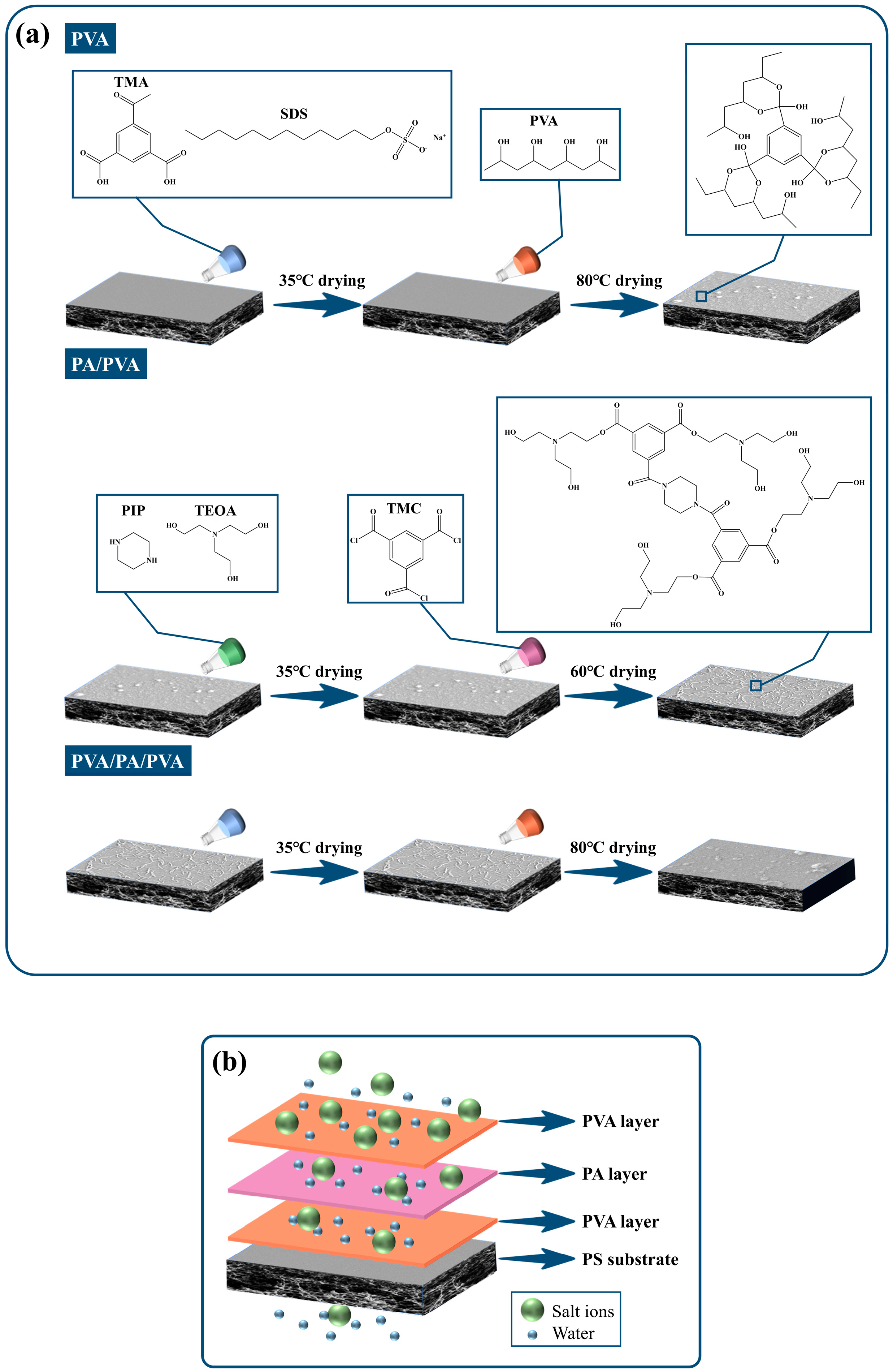
Figure 1. (a) Fabrication process of the PVA/PA/PVA membrane. (b) Schematic illustration of PVA/PA/PVA membrane with sandwich structure.
Water 16 02752 g001
Figure 2. The ATR-FTIR spectra of the membrane.
Water 16 02752 g002
Figure 3. Surface chemical characterization of the membranes by XPS: (a) XPS survey spectra; C 1s spectrum of (b) PVA-0.20, (c) PA/PVA-0.20, and (d) PVA-0.20/PA/PVA-0.20.
Water 16 02752 g003
Figure 4. SEM images of the top surfaces of (a) PS, (b) PVA-0.20, (c) PA/PVA-0.20, and (d) PVA-0.20/PA/PVA-0.20; cross-sectional images of (e) PS, (f) PVA-0.20, (g) PA/PVA-0.20, and (h) PVA-0.20/PA/PVA-0.20; and AFM images of (i) PS, (j) PVA-0.20, (k) PA/PVA-0.20, and (l) PVA-0.20/PA/PVA-0.20.
Water 16 02752 g004
Figure 5. Water contact angle of the membranes.
Water 16 02752 g005
Figure 6. The impact of PVA concentration on membrane separation performance: (a) pure water flux and (b) rejection of Na2SO4 and NaCl.
Water 16 02752 g006
Figure 7. The impact of PVA concentration on the separation performance of the PA/PVA membranes: (a) pure water flux and (b) rejection of Na2SO4 and NaCl.
Water 16 02752 g007
Figure 8. Separation performance of the PVA/PA/PVA membranes.
Water 16 02752 g008
Figure 9. Salt rejection and permeate flux of the PVA-0.20/PA/PVA-0.20 membrane.
Water 16 02752 g009
Figure 10. The dye adsorption content on TFC and PVA-0.20/PA/PVA-0.20 membranes with static adsorption for different dyes.
Water 16 02752 g010
Figure 11. Time-dependent normalized fluxes (Jt/J0) for the control TFC membrane and PVA-0.20/PA/PVA-0.20 membrane in filtration aqueous solution containing: (a) BSA and (b) SA.
Water 16 02752 g011
Figure 12. The chlorine resistance of the control TFC membrane and PVA-0.20/PA/PVA-0.20 membrane: (a) pure water flux and (b) Na2SO4 rejection.
Water 16 02752 g012
Table 1. The surface roughness of the membranes.
MembraneRq (nm)Ra (nm)
PS4.5 ± 0.13.5 ± 0.4
PVA-0.2014.5 ± 0.311.3 ± 0.1
PA/PVA-0.2024.2 ± 0.416.5 ± 0.2
PVA-0.20/PA/PVA-0.2011.2 ± 0.28.8 ± 0.3
Table 2. Comparison of the separation performance of the control TFC and PVA-0.20/PA/PVA-0.20.
Flux (LMH/bar)Na2SO4 Rejection (%)NaCl Rejection (%)
TFC5.62 ± 0.9697.47 ± 1.8948.17 ± 2.78
PVA-0.20/PA/PVA-0.2022.05 ± 1.0596.57 ± 2.5719.58 ± 0.58
Table 3. The rejection rates of different organic dyes by the control TFC and PVA-0.20/PA/PVA-0.20.
Control TFCPVA-0.20/PA/PVA-0.20
Flux (LMH/bar)Rejection (%)Flux (LMH/bar)Rejection (%)
NR5.48 ± 0.1888.50 ± 0.1121.83 ± 0.2184.03 ± 0.13
Rh B5.26 ±0.2598.10 ± 0.1321.64 ± 0.3197.91 ± 0.22
VB4.99 ± 0.1499.93 ± 0.0520.25 ± 0.2499.92 ± 0.05
EBT5.37 ± 0.3198.90 ± 0.1120.5 ± 0.1698.61 ± 0.34
CR5.01 ± 0.2399.94 ± 0.0320.23 ± 0.4199.93 ± 0.03
Table 4. Characteristics of different organic dyes.
DyeMW (g/mol)Charge
NR288.8Positive
Rh B479.0Positive
VB506.1Positive
EBT461.4Negative
CR696.7Negative
Table 5. Antifouling performance of the membranes for different solutions.
Feed SolutionControl TFCPVA-0.20/PA/PVA-0.20
FDR (%)FRR (%)FDR (%)FRR (%)
BSA18.33 ± 0.3194.01 ± 0.274.32 ± 0.1198.82 ± 0.09
SA24.43 ± 0.2691.57 ± 0.199.13 ± 0.1697.07 ± 0.12
Table 6. Comparison of the properties of the prepared multilayer separation membranes.
MembranePermeate Flux
(LMH/bar)
Na2SO4 Rejection
(%)
NaCl Rejection
(%)
Ref.
PA-PAH-0.2/PSf12.5098.9021.01[62]
TFNC-SiO2-219.6096.5065.00[63]
PA/COF2/PES13.5098.7021.80[64]
TFC-hg15.5099.1022.05[65]
Gel-PA13.2298.2311.95[66]
TFCnO-5011.1099.0041.12[67]
PVA-0.20/PA/PVA-0.2022.0596.5719.58This study
Disclaimer/Publisher’s Note: The statements, opinions and data contained in all publications are solely those of the individual author(s) and contributor(s) and not of MDPI and/or the editor(s). MDPI and/or the editor(s) disclaim responsibility for any injury to people or property resulting from any ideas, methods, instructions or products referred to in the content.