Abstract
The current literature analyzing the dynamic response of coupled pipelines neglects the crucial interplay between the pipelines themselves and these constraints. This overlooked interaction has substantial influence on the fluid–structure coupling response, particularly in scenarios involving continuous constraints. We focus on a piping system surrounded by compacted soil, which is regarded as unbounded homogeneous elastic soil that suffers from water hammer. This study established a one-dimensional model for water pipe-embedded compacted soil with fluid–structure–soil interaction. Taking fluid–structure–soil interaction into account, fluid–structure interactions (FSIs) include Poisson coupling, junction coupling emerging at the fluid–structure interface, and pipe–soil coupling (PSC) emerging at the pipe–soil interface. In this study, as soil is assumed to be a homogeneous, isotropic elastic material, the coupling responses are more complex than those of an exposed pipe, and the relevant mechanisms justify further exploration to obtain well-predicted results. To mathematically describe this system considering fluid–structure–soil interaction, the four-equation FSI model was modified to accommodate the piping system surrounded by unbounded homogeneous elastic soil, employing the finite volume method (FVM) as a means to tackle and solve the dynamic problems with FSI and PSC, which partitions the computational domain into a finite number of control volumes and discretizes governing equations within each volume. The results were validated by the experimental and numerical results. Then, dynamic FSI responses to water hammer were studied in a reservoir–pipe–reservoir physical system. The hydraulic pressure, pipe wall stress, and axial motion were discussed with respect to different parameters. With the PSC and FSI taken into account, fluid, soil, and pipe signals were obviously observed. The results revealed the structural and fluid modes. Dynamic responses have been proven to be difficult to understand and predict. Despite this, this study provides a tractable method to capture more accurate systematic characteristics of a water pipe embedded in soil.
1. Introduction
Water-conveyance pipelines have been widely used in marine engineering, petrochemical engineering, energy and power engineering, spacecraft power systems, and daily life. Stimuli inside and outside a pipe wall trigger pressure pulsations, leading to structural vibrations and new pressure pulsations; this is called fluid–structure interaction [1]. FSIs play an important role in water hammer pressure and piping vibration [2].
Many studies pay attention to the FSI problem in exposed pipes. In an exposed pipe, the forms of FSI include Poisson coupling, junction coupling, and friction coupling. Friction coupling is a weak type of coupling and can be ignored [3]. During water hammer, a four-equation model is appropriate to simulate straight piping. Regarding water hammer with FSI, scholars have obtained many achievements [3,4,5,6,7]. Poisson coupling occurs consistently in the whole pipeline, whereas junction coupling only happens locally in locations like elbows, branches, valves, boundaries, and variable cross-sections [3]. Furthermore, friction coupling has the weakest response [4]. Meanwhile, junction coupling and Poisson coupling, as two important coupling forms, produce pressure heads larger than the classical water hammer and greatly depend on the robustness of the system [4].
The FSI responses are related closely to the boundary conditions and layout forms of the piping [5,6,7]. An FSI analysis should be conducted in accordance with the operating conditions. In order to simulate different operating environments of pipes, some results have been acquired based on exposed pipe models with different boundary conditions. A literature review has shown that the complex restrictions of water pipes can be simplified to supports [8]. With regard to pipeline constraints, Li et al. [9] proposed an aggregative model of fluid boundary conditions. This model can constrain elastic supports with varying rigidities and directions, which can be simplified to fluid impedance. Liu and Li [10] analyzed an elastic multi-support pipe using six equations and simulated the restrictions on piping using six elastic spring models [11,12]. All the listed studies have been based on the assumption that the pipe restriction is discrete, and thus the influences on the pipe from restrictions are simplified as elastic supports [8,9,10,11,12,13] and the interaction between the pipe and the restriction is ignored.
The previous research endeavors have prominently incorporated continuous constraint conditions as pivotal boundary factors, meticulously discretizing them into individual computational cells. This approach has primarily illuminated how these constraints directly modulate the dynamic behavior of water-delivery systems, including pressure fluctuations and flow rate variations, thereby laying a robust foundation for understanding and predicting system responses. However, as engineering practices deepen and theoretical research progresses, there is a pressing need for a holistic evaluation of water-conveyance systems’ performance in intricate environments.
In light of this necessity, our study presents an enhanced and comprehensive analytical framework, building upon and extending prior works. For water pipes embedded in compacted soil, we transcend the conventional treatment of soil as a rigid support, which solely considers its axial behavior. This paradigm shift necessitates a model construction that better aligns with real-world physical processes.
To this end, our study innovatively incorporates the radial coordinated deformation mechanism of soil, which underscores the substantial deformation and displacement that occurs in the radial direction under the influence of multiple factors like the fluid pressure, pipeline structural stress, and soil properties. This deformation not only alters the pipeline’s geometry and constraint conditions, but also reciprocates through fluid–structure–soil interaction, fostering a complex coupling effect.
Guided by this understanding, we have theoretically derived and mathematically modeled a one-dimensional control equation tailored to describe such coupling effects. This equation integrates the continuity, momentum, and mechanical equilibrium equations of the fluid–structure system while seamlessly incorporating the radial coordinated deformation law of soil, which culminates in a mathematical tool that comprehensively captures the dynamic behavior of water-conveyance systems. By solving these control equations, we can now predict and evaluate the performance of water transport systems embedded in compacted soil with unprecedented accuracy.
2. Materials and Methods
2.1. Four-Equation Model of Fluid–Structure Interactions
This study disregards Coriolis and centripetal forces; furthermore, axial coupling in a straight pipe can be decoupled from its X–Y plane, Y–Z plane, and torsional coupling [14]. The model is designed in two dimensions and takes into account radial vibration as a primary consideration. By averaging the stress and displacement in a section, a one-dimensional, four-equation model is derived to describe a water-pipe system [4].
Motion equation for water:
Continuity equation for water:
Equation of motion for the pipe:
Constitutive equation for the pipe
where V is the average flow velocity within the interface; P is the average pressure in the interface; v(r) is the 2D flow velocity at the cross-section; p(r) is the 2D pressure at the cross-section; Vr is the radial flow velocity of the fluid; uz is the axial vibration velocity of the pipeline; σz is the axial stress on the pipe wall; σθ is the circumferential stress on the pipe wall; σr is the radial stress at the pipe wall; K is the volume modulus of incompressible fluid; E is the elastic modulus of the pipe material; R is the pipe diameter; e is the pipe wall thickness; ρf is the density of water; ρt is the density of steel; and εz is the axial strain of the pipe wall.
2.2. The Relationship of p|r=R, Pb, P, and σz in An Embedded Pipe
After the soil undergoes compaction, the interstitial spaces between its particles diminish significantly, leading to a substantial enhancement of the soil density. This, in turn, bolsters the soil’s overall strength and stability. Furthermore, the compaction process mitigates unevenness and anisotropy within the soil, fostering a more uniform and consistent macroscopic appearance. Consequently, it is reasonable to assume that compacted soil behaves as a uniform, continuous, and homogeneous medium.
When a pipe is embedded in this type of compacted soil, when hydraulic transients occur, the pipe’s deformation is minimal relative to its dimensions (in agreement with the small deformation hypothesis); this scenario permits us to overlook the nonlinear soil behaviors induced by pipeline deformation and to presume that the soil retains its inherent elastic properties in the vicinity of the pipeline.
Relying on these two fundamental assumptions—homogeneity and continuity of soil, alongside tiny but not negligible deformation—we can streamline the soil’s constitutive equation into an elastic model. This model establishes a direct, linear correlation between soil stress and strain, as defined by the generalized Hooke’s law. Critically, elastic deformation in this model is reversible; upon the removal of external forces, the soil regains its original form and dimensions. This feature makes the elastic model exceptionally suitable and accurate for modeling soil responses to hydraulic transients in pipes, as it simplifies computations while maintaining a satisfactory level of accuracy and reliability in the results [15,16].
The coupling mechanism becomes elusive because the FSIs in a water pipe embedded in compacted soil include Poisson coupling, junction coupling, and PSC. A diagram of the stress acting on the pipe wall is shown in Figure 1. When the soil is uniformly and isotropically compacted, its mechanical characteristics exhibit remarkable stability, which aligns well with the linear premise inherent in the model. Consequently, the soil’s supportive role towards the pipe can be precisely replicated via an array of linear springs. For pipe materials possessing high rigidity, the Winkler model is particularly suitable. Furthermore, the transient operations of the pipeline water-delivery system do not elicit significant nonlinear behavior from the soil or pipeline materials; thus, the linear Winkler model proves effective in capturing the intricate dynamics of pipe–soil interactions. The entire pipe ring is assumed to be subjected to a uniform Pb.
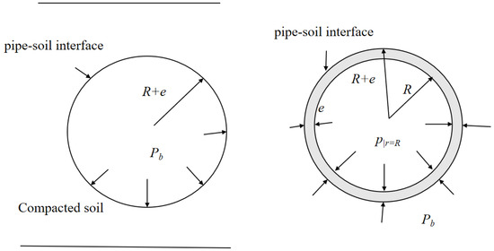
Figure 1.
Diagram of stresses acting on the pipe wall (cross-sectional view). Here, Pb and p|r=R represent the radial pressures at the outer and inner pipe walls, respectively.
The entire structure is symmetrical, and the stress is uniformly distributed along the pipe ring. Circumferential and radial stresses are functions of the radial coordinate r [17,18], and the Lame solution for stress is applied to the pipe wall [19]. The following expressions are derived:
Here, R is the internal diameter of the pipe and e is the pipe wall thickness. At the pipe–soil interface, σb = Pb and εr|r=R+e = εrm|r=R+e. Here, εrm is the radial strain of elastic soil [20]. In the radial direction of the boundless elastic soil, the relationship between stress and strain is expressed as follows [21]:
where Es is the elastic modulus of the soil; σz is the axial stress of the pipe; E is the elastic modulus of the pipe; and ν is the pipe’s Poisson ratio. In Equations (4) and (5), Pb is linearly represented by p|r=R and σz. Equation (7) can be written as:
Considering the differences between the sectional average pressure and the pressure at the pipe–soil interface, a radial motion equation for fluid is established as follows [22,23]:
where ρf is the fluid density. The radial motion equation for the pipe wall embedded in compacted soil is formulated as follows:
where ρt is the pipe wall density. The following equations obtained from Equation (10) are substituted into Equation (8). In Equations (8) and (9), Pb and p|r=R can be represented linearly by P and σz, as shown in the following:
These variables play an important role in FSI responses in a water pipe embedded in soil, as indicated in Section 2.3.
2.3. Four-Equation Model for Fluid–Structure–Soil Interactions
The radial velocity of fluid Vr at the interface is equal to the radial coupling velocity of the pipe wall ur, as follows [24]:
Using Equations (10) and (11), Equation (12) is transformed into the relationships between Vr and R and P and σz, as shown in the following:
Thus, the continuity equation for fluid in an embedded water pipe is as follows:
On the other hand, in accordance with Equations (4) and (5), the sum of the hoop and radial mean stresses in a buried pipe is as follows:
For convenience, Equation (5) is written as follows:
Thus, the constitutive equation for a pipe in an embedded water pipe is as follows:
The one-dimensional four-equation model of FSIs describing a piping system embedded into a boundless soil consists of Equations (1), (3), (15) and (18), as shown in the following:
3. Numerical Algorithm
In fluid–structure–soil interactions, mismatch between the pressure wave and stress wave makes it difficult to apply methods used to determine characteristics. In this study, the finite volume method (FVM) is found to provide an accurate solution by solving the integral equation for each control volume [25] and clarifying the physical definition of each term in the equation [26]. T555his approach is particularly advantageous in simulating FSIs, as it ensures stability even in the presence of strong coupling between the fluid and structure domains. By discretizing the equations governing the FSI model in this manner, we can accurately capture the dynamic behavior of the system and obtain reliable predictions of its response under various conditions [14]. Therefore, the FVM is adopted to determine the FSIs in the piping system. The specific derivation of Equation (19) is shown as follows:
This method discretizes Equations (21)–(26) by using the control volume integral and integrating the continuity equation from t to t +Δt in the control volume. In this way, the integral equation in the control volume can be obtained. The Crank–Nicolson implicit format for the time center difference is also adopted to process the partial differential terms and obtain the discrete format of the FSI model with second-order accuracy and unconditional stability [27].
The discretization process is carried out by dividing the fluid domain into a series of control volumes, within which the fluid properties and their temporal evolution are assumed to be uniform. This approximation allows us to represent the continuous fluid behavior within each control volume through a set of discrete equations.
By integrating the continuity equation from time t to t +Δt within each control volume, we can establish a discrete representation of the fluid flow within that volume. The Crank–Nicolson implicit format is then employed to handle the partial differential terms, ensuring both second-order accuracy and unconditional stability in the time-stepping process.
This approach is particularly advantageous in simulating fluid–structure interactions (FSIs), as it ensures stability even in the presence of strong coupling between the fluid and solid domains. By discretizing the equations governing the FSI model in this manner, we can accurately capture the dynamic behavior of the system and obtain reliable predictions of its response under various conditions [27].
The FVM is used to solve the following:
As an important component of a pipe water-delivery system, the mathematical model of ancillary buildings is solved using the finite volume method as follows:
Similarly, the values of the variables defined at the midpoint between the (n + 1/2)th and (n − 1/2)th cell are shown as follows:
where Δt is the time step and Δz is the length of each control volume.
On the basis of Equation (25), the iterative soil between adjacent time steps, for the water-conveyance system, is modeled as follows:
Here, .
As seen in Equation (25), Ci relates to the values of Qn at the ith and (i + 1)th cells; Ci is known at the (n + 1)th time step. Thus, Qi−1 at the (n + 1)th time step can be solved using Equation (24). In these equations, i = 1 ∽ N, where i =1 and N + 1 refer to the inlet and outlet of the virtual cell, respectively, and the coefficient of the soil corresponds to T1and TN.
4. Testing and Analysis
With Es/E = 0, from Equation (18) we can obtain Pb = 0, p|r=R ≠ P, which means that there is no PSC in this system and that there are still pressure differences in the radial direction of the pipe. Thus, only Poisson coupling and junction coupling are present in the system, with unavoidable piping vibrations, and our model degenerates into a four-equation model. On the other hand, with Es/E = ∞, the results display Pb = p|r=R = P. Thus, there is no pressure difference between the inside and outside of the pipe wall, and the vibration of the pipe is not considered. Our model reduces to a classical two-equation model. As shown in the above-mentioned results, this model has wide applicability and can be jointly verified using the suspension pipe experimental results and the numerical results simulated by a two-equation model.
4.1. Verification
Figure 2 shows the device implemented in [28], which is a 4.5 m double-layer pipe fixed by suspension to ensure that it is only impacted by a 5.006 m-long solid steel rod during the experiment. It is worth noting that both the inner and outer pipelines are made of elastic materials, which enable them to undergo appropriate deformation under stress and, subsequently, to restore their original state. This characteristic is highly consistent with the characteristics of pipeline materials used in engineering practices.

Figure 2.
Experimental device in [29].
It is particularly crucial that the cross-sectional area of the outer-layer pipeline is designed to be much larger than that of the inner-layer pipeline. This design makes the interaction mechanism between the inner and outer layers more similar to the complex coupling relationship between the pipeline and the compacted soil, i.e., the pipe–soil coupling effect.
Using data obtained from this experimental setup, we can effectively verify the response characteristics of water pipelines buried in compacted soil under dynamic conditions.
4.1.1. Boundary Conditions
If uz < Vr, we consider the inertia of the plug and the axial motion equation at the impact end [29]:
If uz > Vr or uz = Vr, Equation (35) can be simplified to:
4.1.2. Verification Results
Conventional modeling approaches frequently regard external constraints (encompassing soil, adjacent rock formations, and other supportive structures) as immutable boundary conditions in fluid–structure interaction problems, overlooking their dynamic responses and feedback mechanisms. This study innovatively incorporates the dynamic influence of these external, continuously evolving constraints into the dynamic system’s interplay with fluids and solid structures. This innovative processing strategy offers a more precise portrayal of the intricate multi-field coupling phenomena encountered in real-world engineering scenarios. By deepening our understanding of the coupling dynamics between the external constraints, fluids, and solids, this model enhances the capability to discern intricate and pivotal physical processes, ultimately enhancing the prediction accuracy.
The axial strike produces a high-frequency pressure fluctuation in the pipe. The time step in the simulations is as small as 10−4 s in order to capture the features of the pressure fluctuation. Figure 3 presents the experimental outcomes, alongside the simulation results, derived from both the traditional model and the advanced FSI and PSC methodologies.
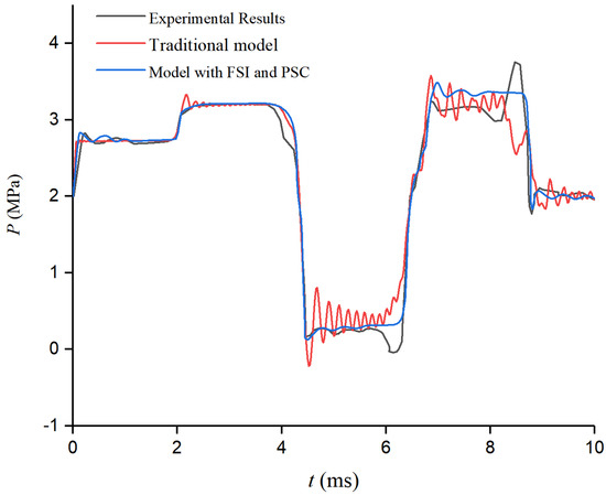
Figure 3.
Numerical and experimental results of dynamic pressure at impact end of a hanging pipe.
As Figure 3 illustrates, the traditional framework neglects the external continuous constraints and their dynamic coupling impacts, leading to unexplained high-order hydraulic oscillations in the numerical outcomes. These oscillations likely stem from model oversimplification, which fails to capture the system’s genuine dynamic nature. In stark contrast, our model, by integrating the dynamics of the external constraints and refining the coupling mechanisms, uncovers the genuine cause of these oscillations—the dynamic deformations of the pipelines and soil. This revelation not only sheds light on the discrepancies in the traditional models but also underscores the superiority of our approach in predicting intricate dynamic behaviors.
As shown in Figure 3, the predictive outcomes of our model not only align closely with the experimental data numerically but also exhibit a high degree of consistency in terms of trend evolution. This highlights the model’s precision and efficacy in depicting actual physical processes, underscoring its value in addressing complex engineering challenges.
4.2. Verification Using Numerical Simulations
A buried-pipe water-conveyance across a highway is taken as a typical example in this section; we assume that the soil is elastic. As shown in Figure 4, the length of the pipeline is L = 100 m; the thickness diameter ratio is e/R = 0.1; E = 200 GPa; ρt = 7800 kg/m3; ν = 0.3; the difference in the water level between the upstream and downstream reservoirs is 4 m; and the weight of the valve is Mv0 = 100 kg. Es is sufficiently large, and the uz and ur of the pipe wall are minimal. We assume that the vibration of the pipe is negligible by setting Es/E > 0.1 (as proven in “Section 5.1”).
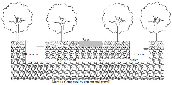
Figure 4.
Side view of the buried-pipe water-conveyance system.
Figure 5 shows that the FVM is convergent with Δt < 10−3 s, and the main frequencies of the water supply system are less than 104 Hz [19]; thus, the time step Δt = 10−4 s can display the most fluid and structural patterns. Accordingly, the length of each control volume Δx = 0.1 m.
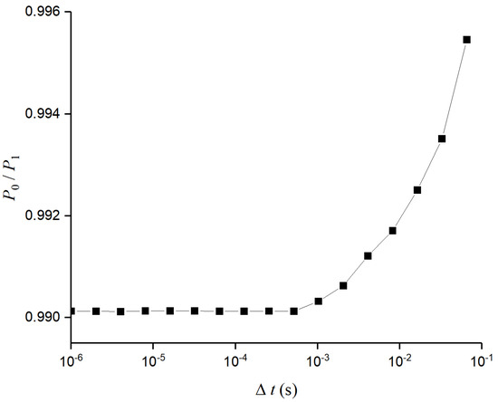
Figure 5.
Verification of mesh independent of Δt.
The dynamic response of the water-conveyance system shown in Figure 4 is caused by the closure of the valve; the boundary conditions of the valve are described as follows [30]:
Here, K is the amplification factor for the flow regulation, and τ is the valve opening. Equation (37) gives a different form of the equation:
From Equation (38), the adjacent time step iteration equation for valve operation can be obtained:
The results with Es/E = 1, simulated by the derived four-equation model, are similar to those without FSIs. The numerical results of the two-equation model and this model are presented in Figure 6. It is evident that the results of the two models are almost identical. A comparison of the results reveals that our derived model is suitable for piping systems surrounded by soil, even in extreme conditions. Based on the case shown in Figure 5, we present a detailed analysis and discussion.
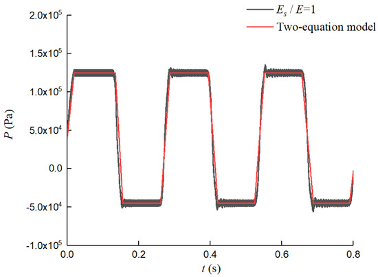
Figure 6.
Numerical dynamic pressure at the valve.
4.3. Analysis
According to Equations (14) and (17), the radial expansion of the pipe wall (from FSIs) causes the restriction of the elastic soil on the pipe wall. Thus, the PSC is an important coupling form of FSI. We obtained numerical results for Pb and p|r=R, as shown in Figure 6; it is difficult to determine the degree of PSC responses using traditional computational models.
By changing Es/E = 0 to 1, we obtain, correspondingly, a value of Pb/p|r=R, ranging from 0 to 1. According to Equations (8) and (9), and considering the FSIs, the fluid energy is transmitted to the pipe wall and soil and converted into vibration energy in the former and pressure energy in the latter. Pressure energy enhancement (i.e., Pb was enhanced) was accompanied by a weakening of the vibration energy, which reduced the differences between Pb and p|r=R, (Pb/p|r=R, enlarged). Therefore, the enhancement of the restrictions on the pipe is always accompanied by an increase in Pb/p|r=R. From this perspective, Pb/p|r=R, can reflect the degree of the PSC responses. Pb/p|r=R, varies with Es/E and σz, as shown in Figure 7 and Figure 8, respectively.
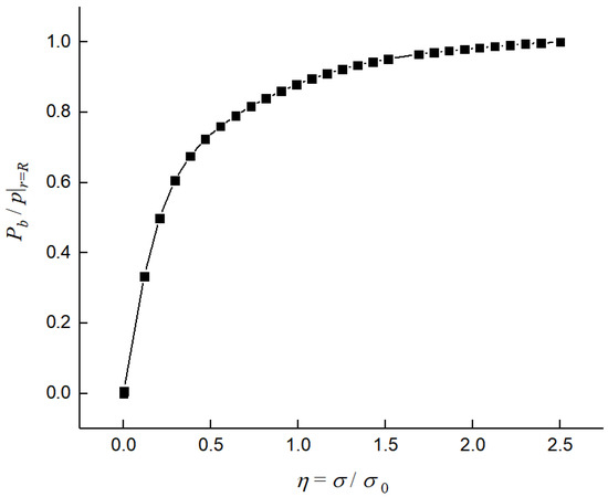
Figure 7.
Variation in Pb/p|r=R, with η in a water pipe surrounded by soil.
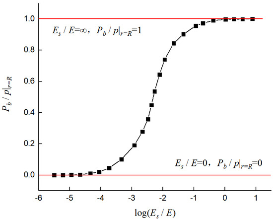
Figure 8.
Variation in Pb/p|r=R, with log(Es/E) in a water pipe surrounded by soil.
Equations (10) and (11) reveal that we acquired the waveform of Pb/p|r=R, which varies with Es/E or σz, as shown as in Figure 7 and Figure 8. From Figure 7, we found that the variation in Pb/p|r=R becomes smaller with a larger η (η = σ/σ0), which is explained as follows. In the low-stress region, the pipe has a greater stiffness and the radial vibration accelerates faster, as shown in Equation (7). Figure 6 shows that the differences between the radial pressures on the inside and outside of the pipe wall increase, i.e., Pb/p|r=R has a greater difference, and pipe–soil coupling becomes stronger. On the other hand, the level of pipe–soil coupling in the low-stress area exhibits a large change; it is 30 times that of the high-stress area. This shows that, in the weak-coupling area, the pipe–soil coupling increases rapidly and then tends to ease until it is even and stable, which also shows that it is necessary to consider fluid–pipe–soil coupling in the refined model of fluid–structure interactions.
When log(Es/E) < −4, all the coefficients, including 2m, 2n, k, and h, produced by the FSIs and pipe–soil coupling are regarded as constants under different values of Es. In this range, the wave speeds are identical; thus, the frequencies and robustness of the system can be regarded as constants. Furthermore, if the coupling responses include amplitudes, phases, and frequencies, they are regarded as identical, and the PSC is omitted; thus, the pressure wave speed is close to that in an exposed pipe, which corresponds to the left straight segment shown in Figure 8.
In the event of an accident or misoperation within a pipeline, various internal and external excitations can arise, triggering transient-flow-boosting and pressure-reducing waves that propagate across the entire system, which can lead to periods of overpressure and low pressure [31]. These pressure oscillations result in pipeline deformation, which propagates in the form of waves throughout the water-delivery system; in turn, this influences the fluid oscillations and the deformation of the pipe causes deformation of the soil–pipe interface. Due to the substantial thickness of the soil [32], the axial deformation is negligible, and only the radial deformation is considered. However, the entire water supply system undergoes deformation, leading to soil deformation in each calculation unit system along the pipeline’s axis. This process dissipates the energy transmitted from the pipeline, mitigating the pipeline deformation. In this study, the PSC–FSI relationship is taken into account; the revealed mechanisms are as follows.
A stress wave propagates approximately three times faster than a pressure wave; thus, the surge during half of the period can be split into three parts, as shown in Figure 9. In the first part, ur > 0, the expansion of the pipe wall leads to the first pressure drop. Additionally, the robustness of the pipe is strengthened by the PSC, which weakens the pressure drop. Then, in the second part, ur < 0, the pipe wall contracts and compresses the fluid; this phenomenon is called the pumping effect. At the same time, the PSC mitigates this phenomenon. Lastly, in the third part, ur > 0, the axial stress wave bounces back, extending the pipe wall again, so that a pressure drop is caused, and, for the same reason as that in part one, the pressure drop is weakened by the PSC.
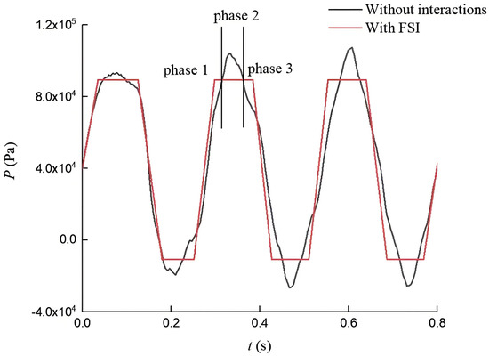
Figure 9.
Dynamic pressure with and without FSIs.
In a buried water piping system, the forms of FSI include Poisson coupling, junction coupling, and PSC, which are related to ν, Mv/Mv0, and Es/E (friction coupling is weak coupling and is ignored [1]). Figure 10 displays the differences in the dynamic water hammer pressure between two different values of ν, Mv/Mv0, and Es/E. The pressure drop and ‘pump’ effect are the most obvious variation from Es/E = 10−3 to Es/E = 10−1 and lead to the largest difference in dynamic water hammer pressure. This indicates that PSC is the most important coupling form in a water pipe embedded in elastic soil.
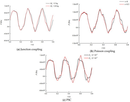
Figure 10.
Dynamic pressure at the valve varies with one of the three couplings.
From Figure 10, it can be seen that PSC emerges in the buried pipe, which causes more complex coupling responses in the buried tube. Specifically, PSC emerges at the pipe–soil interface; from the energy perspective, a portion of the water hammer energy in the system is consumed or extracted by the axial and radial vibration of the pipe, and a part of the pipe–wall energy is absorbed by the soil.
5. Results and Discussion
5.1. Wave Propagation Speed
Only stress waves and pressure waves propagate in a piping system surrounded by soil, and all the modes of the dynamic pressure and vibration of the pipe wall are attributable to these two waves, particularly the pressure wave.
The wave speed can be written as:
Equation (39) is substituted into Equation (40); here, S = 0, i.e.,
In order to obtain nonzero solutions, the determinant composed of A and B must be zero.
Equation (27) is expressed as follows:
Solving Equation (28), i.e.,
Here,
By solving Equation (44), we obtain two real solutions; they are squares of the stress waves and pressure waves. Specifically, −x/α = cs2 + cf2, θ/α = cs2cf2. Equation (44) indicates that the stress and pressure wave speeds relate to 2m, 2n, h, and k, which are coefficients that vary with Es/E in the set buried pipe
The following results were determined: Es/E= 10−5 − 10, 2m = 2.35 × 10⁻¹¹ Pa−1 − 5.36 × 10⁻¹⁵ Pa−1, 2n = 2.5 × 10⁻¹¹ Pa−1 − 1.36 × 10⁻¹³ Pa−1, h = 0 – −0.0938, and k = 0 – −0.0953. The role of these parameters in determining the pressure wave speeds cannot be ignored. Correspondingly, Figure 11 depicts the relationship between the wave speed and Es/E in detail, shown as in Figure 11.
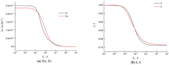
Figure 11.
Variation in 2m, 2n, k, and h with Es/E.
In this range, the added masses and stiffness in the pipe produced by PSC can be ignored. The pressure wave speed is close to that in the exposed pipe, which corresponds to the left straight segment in Figure 12. Theoretically, the complex model can degenerate into four equations for the FSIs in the exposed pipe. On the other hand, under Es/E > 1, the added masses and stiffness in the pipe produced by PSC are rigid enough for the structural vibration to be ignored; thus, dynamic water hammer pressure in this system can be simulated by the classical two-equation model.
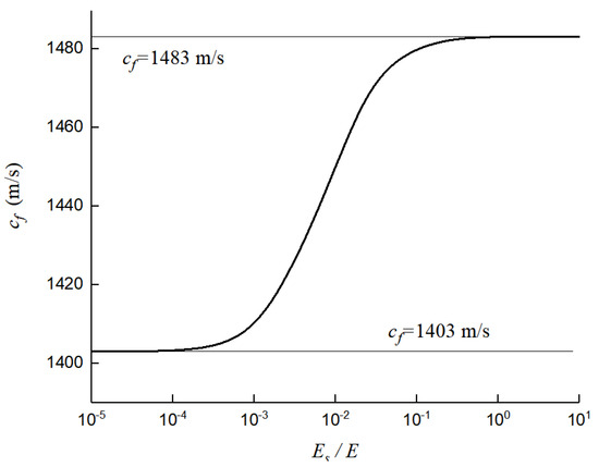
Figure 12.
Variation in pressure wave speed with Es/E.
These results are explained as follows: the buried pipe system becomes more stable and inflexible with larger values of Es/E, equaling that of a pipe showing higher stiffness; then, the fluid is subjected to faster pumping effects, and the pressure wave achieves a faster speed.
5.2. Coupling Responses with Different Es/E
In a buried pipe, the water hammer pressure shows different modes with different FSIs due to PSC [33]; furthermore, the pipe’s dynamic pressure and vibration are related to Es/E. In order to display the influences of Es/E on the coupling responses, we compared the numerical results of the dynamic pressure and the vibration of the pipe at different Es/E values.
With a larger Es/E, the water hammer pressure exhibited a pressure drop in the third stage, and the ‘pump’ effect was weakened by nearly one-third; in addition, the waveform of the dynamic pressure tended to be rectangular. The above-mentioned findings can be explained by the larger additional mass and stiffness with PSC, which weakens the FSI response. Figure 13 shows that the differences in cf between Es/E = 10−3 and Es/E = 10−1 are less than 5.4%; thus, the differences in the water hammer period T = 4L/cf between the two cases are less than 5%, and the spectral response is illustrated in Figure 14.
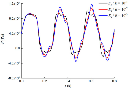
Figure 13.
Numerical dynamic pressure at the valve under different Es/E values.
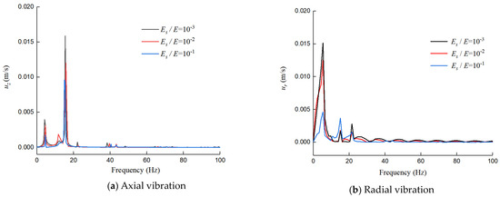
Figure 14.
Vibration velocity in axial and radial directions in the frequency domain under Es/E = 10−3 − 10−1.
Without considering the pipe–soil coupling effect, the system modes are neatly categorized into fluid and structural modes. However, upon fully embracing the intricate interplay between the fluid, structure, and soil, all the vibration modes coalesce into a cohesive system mode. A deep examination of pipeline deformation distinctly reveals the individual traits of the structural, fluid, and soil modes, enabling us to pinpoint the origins of pipeline system modes through intricate data processing techniques.
In the realm of water-conveyance systems, pressure and stress waves dominate the axial propagation. When factoring in fluid–structure–soil coupling, two prominent resonance peaks at 5.3 Hz and 16.0 Hz are highlighted (Figure 14a) which precisely align with the natural frequencies of the water column and steel pipe, respectively. Furthermore, Figure 14b reveals three additional resonance peaks, with frequencies of 5.3 Hz, 16.0 Hz, and 21.0 Hz. These peaks stem from the negligible axial deformation of the soil; however, its radial deformation intricately harmonizes with that of the pipeline. Through the pipe–soil coupling mechanism, the radial deformation frequency of the soil is captured by the pipeline vibrations. Notably, the 6.44 Hz resonance peak intimately correlates with the breathing mode of the pipe wall, mirroring the natural frequency of the water column.
Notably, each peak encapsulates the fundamental and odd harmonics of either the fluid or the structure. Unlike the conventional models, our model innovatively acknowledges the soil’s mitigating influence on the pipeline deformation, as elaborated in Equation (9). This consideration triggers radial variations in the pipe wall’s axial displacement, fostering stretching and compression among the different radial positions. Consequently, the pipeline’s axial potential energy escalates, primarily fueled by the transformation of the water hammer energy. This energy conversion signifies that the structure consumes more water hammer energy during vibrations, thereby attenuating pipeline vibrations, pressure drops, and the “pump” effect, as shown in Figure 13. This cumulative effect further dampens the axial deformation of the pipeline, underscoring its enhanced robustness. Consequently, this model’s predictions exhibit more pronounced modal peaks, particularly at higher frequencies, as clearly depicted in Figure 13.
Figure 13 and Figure 14 show that the fundamental frequency of the pipeline vibrations maintains a relatively uniform pattern across varying elastic modulus ratios (Es/E); this uniformity is primarily evident in the frequency spectrum, whereas notable disparities emerge in the manifestation of the vibration energy. Notably, alterations in the Es/E ratio significantly diminish the vibration energy within the pipeline, particularly those energies stemming from the water hammer phenomenon. Upon examining shifts in the Es/E ratio, we uncovered a transformation in the interplay due to FSIs and PSC. This transformation not only modulates the pipeline’s capacity to mitigate and disperse water hammer impacts but also directly contributes to the attenuation of vibration energy. More specifically, an augmentation in the Es/E ratio signifies an enhancement in the pipeline material’s relative stiffness compared to its internal environment. Consequently, the pipeline becomes more adept at harnessing and dissipating vibration energy through its own elastic deformation during water hammer events, thereby mitigating the transmission of energy to other pipeline segments. Conversely, a decrease in the Es/E ratio diminishes the material’s relative stiffness, weakening its ability to absorb and disperse water hammer energy, which in turn fosters the propagation and accumulation of vibration energy throughout the pipeline system.
5.3. Discussion of Limitations
When delving into the intricate dynamics of buried water pipelines within soil, it is imperative to acknowledge the system’s profound complexity as a fluid–structure–soil-coupling entity. This study endeavors to dissect the dynamic behavior of water-conveyance systems under a set of assumptions that streamline the analysis: soil is treated as an elastic, continuously deformable medium undergoing minor distortions, while the pipeline and soil deformations are linearized for simplicity. While this approach alleviates the problem’s intricacy and renders the analysis more tractable, it inherently introduces limitations that warrant consideration.
In the realm of practical engineering, particularly where geological complexities abound or pipelines endure substantial loads, soil and pipeline deformations frequently manifest pronounced nonlinear traits. This nonlinearity not only reshapes the pipeline’s geometry and constraint conditions but also intricately influences fluid flow dynamics through soil–structure interactions. Consequently, future endeavors should aspire to incorporate nonlinear constitutive models that capture the nuanced deformation behavior of both soil and pipelines, thereby enhancing the fidelity of dynamic response predictions under operational conditions.
The simplification of soil as a purely elastic continuum overlooks its multifaceted material properties, including its plasticity, viscosity, and anisotropy, which are pivotal in governing the soil’s mechanical response and significantly impact water pipeline dynamics. To address this, future research should endeavor to adopt more sophisticated soil models, such as elastoplastic and viscoelastic formulations, which holistically account for the influence of soil’s material attributes.
Moreover, while this study offers an initial glimpse into the fluid–structure–soil coupling effect, the depth of this exploration may be constrained by the simplifying assumptions employed. To achieve a more precise portrayal of the system’s dynamic behavior, future studies should refine the coupling mechanism and carefully examine the intricate interplay and feedback loops between fluid pressure, pipeline stress, and soil deformation.
6. Conclusions
Fluid–structure–soil interactions should be considered in a piping system surrounded by a boundless soil that includes FSIs and PSC. Furthermore, the nature of piping system’s mechanical behavior has long been elusive and is only partially understood. In order to study the various coupling responses in this type of piping system, while considering the two interactions, a one-dimensional, four-equation model of FSIs was derived for. The feasibility of solving this model using the FVM was verified by the experimental results and the typical numerical result.
Pipe–soil interaction represents the crucial coupling phenomenon that occurs when a pipe is embedded within compacted soil. The degree of this coupling is intimately related to the Es/E, and it exerts a significant influence on wave propagation velocities, the characteristics of the pipe vibrations, and the transient pressure. With an Es/E value from 10−3 to 10−1, the vibration velocity in the axial direction constitutes two-thirds, and the vibration velocity in the radial direction constitutes one-third.
The axial vibration of a water pipe embedded in compacted soil is predominantly influenced by the effect of the pipeline structure's stiffness and mass distribution and the fluid’s flow characteristics, as well as the soil’s axial restraint capabilities, on the pipeline. In this particular mode, the dynamic effects imparted by the fluid become paramount, particularly during transient flow conditions within the pipeline. The inertial forces and pressure waves generated by the fluid propagate vigorously within the pipeline, eliciting substantial axial vibrations. Consequently, this vibration mode is commonly designated as the “fluid mode”, as it is fundamentally governed by the dynamic behavior of the fluid itself.
Radial vibration involves deformations of a pipe in a direction perpendicular to its axis, primarily reflecting the intricate interplay between the pipeline and the surrounding soil, and the elastic properties of the compacted soil exert a prominent influence on these radial vibrations. As the pipeline undergoes internal pressure fluctuations, the soil’s supportive nature towards the pipeline alters, triggering radial vibrations. At this juncture, the structural attributes of the pipeline, encompassing factors such as the wall thickness and material composition, become paramount, as they dictate the pipeline’s resilience against deformation. Consequently, this vibration mode embodies the essence of the “structural mode”, which is predominantly shaped by the mechanical properties inherent to the pipe itself, along with the dynamic bracing conditions offered by the soil.
By incorporating additional motion modes, such as those encountered in aircraft and ships, into the analysis, we can delve deeper into solving the transient behavior of mechanical and hydraulic pipelines. This approach enables a more comprehensive understanding of the dynamic characteristics of these systems under various operational conditions.
Author Contributions
Conceptualization, Q.G. and H.X.; methodology, Q.G.; software, Q.G.; validation, Q.G., H.X. and M.X.; formal analysis, Q.G.; investigation, H.X.; resources, G.X.; data curation, H.X.; writing—original draft preparation, Q.G.; writing—review and editing, Q.G.; visualization, G.X.; supervision, M.X.; project administration, G.X. All authors have read and agreed to the published version of the manuscript.
Funding
This research received no external funding.
Data Availability Statement
The datasets generated and analyzed during the current study are available from the corresponding author upon reasonable request.
Conflicts of Interest
The authors declare that they have no competing financial interests or personal relationships that could have appeared to influence the work reported in this paper.
References
- Plouraboué, F. Review on water-hammer waves mechanical and theoretical foundations. Eur. J. Mech. B/Fluids 2024, 108, 237–271. [Google Scholar] [CrossRef]
- Bayle, A.; Plouraboué, F. Low-Mach number asymptotic analysis of fluid–structure-interaction (FSI) pressure waves inside an elastic tube. Eur. J. Mech. B/Fluids 2023, 101, 59–88. [Google Scholar] [CrossRef]
- Aliabadi, H.K.; Ahmadi, A.; Keramat, A. Frequency response of water hammer with fluid-structure interaction in a viscoelastic pipe. Mech. Syst. Signal Process. 2020, 144, 106848. [Google Scholar] [CrossRef]
- Hosseini, R.S.; Ahmadi, A.; Zanganeh, R. Fluid-Structure interaction during water hammer in a pipeline with different performance mechanisms of viscoelastic supports. J. Sound Vib. 2020, 487, 115527. [Google Scholar] [CrossRef]
- Gao, P.; Yu, T.; Zhang, Y.; Wang, J.; Zhai, J. Vibration analysis and control technologies of hydraulic pipeline system in aircraft: A review. Chin. J. Aeronaut. 2021, 34, 83–114. [Google Scholar] [CrossRef]
- Yu, Y.; Ma, W.; Li, Z.; Zhang, B.; Zeng, Q.; Ding, H.; Wang, X.; Dong, Z. Prediction of erosion defects and buckling pressure of pipe bend based on bidirectional fluid-structure interaction method. Tribol. Int. 2024, 197, 109759. [Google Scholar] [CrossRef]
- Hu, J.; Wang, X.; Wang, Y.; Huang, Y.; Chai, T.; Sun, K.; Wang, Z. Analysis of dynamic characteristics of whipping effect on l-shaped main steam pipe considering fluid-structure interaction effect. Int. J. Impact Eng. 2024, 190, 104988. [Google Scholar] [CrossRef]
- Yang, K.; Li, Q.S.; Zhang, L.X. Longitudinal vibration analysis of multi-span liquid-filled pipelines with rigid constraints. J. Sound Vib. 2004, 273, 125–147. [Google Scholar] [CrossRef]
- Li, S.; Liu, G.; Chen, H. Pressure wave propagation characteristics in fluid-filled pipes with fluid–structure interaction. J. Vib. Shock 2012, 31, 177–182. [Google Scholar]
- Liu, G.; Li, Y. Vibration analysis of liquid-filled pipelines with elastic constraints. J. Sound Vib. 2011, 330, 3166–3181. [Google Scholar] [CrossRef]
- Li, S.; Liu, G.; Kong, W. Vibration analysis of pipes conveying fluid by transfer matrix method. Nucl. Eng. Des. 2014, 266, 78–88. [Google Scholar] [CrossRef]
- Roohollah, Z.; Ahmadi, A.; Keramat, A. Fluid–Structure interaction with viscoelastic supports during waterhammer in a pipeline. J. Fluids Struct. 2015, 54, 215–234. [Google Scholar]
- Adamkowski, A.; Henclik, S.; Janicki, W.; Lewandowski, M. The influence of pipeline supports stiffness onto the water hammer run. Eur. J. Mech. B/Fluids 2016, 61, 297–303. [Google Scholar] [CrossRef]
- Xu, Z.L. Elasticity; Higher Education Press: Beijing, China, 2006. [Google Scholar]
- Firouzi, A.; Yang, W.; Shi, W.; Li, C.Q. Failure of corrosion affected buried cast iron pipes subject to water hammer. Eng. Fail. Anal. 2021, 120, 104993. [Google Scholar] [CrossRef]
- Lee, Y.J.; Feng, M.Q.; Lee, E.T. Deflection of Buried Prestressed Concrete Cylinder Pipe with Soil-Pipe Interaction. KSCE J. Civ. Eng. 2014, 18, 2191–2195. [Google Scholar] [CrossRef]
- Rajbamshi, S.; Guo, Q.T.; Zhan, M. Model updating of fluid-structure interaction effects on piping System. Dyn. Substruct. 2020, 4, 133–139. [Google Scholar] [CrossRef]
- Mahmoodi, R.; Zolfaghari, A.; Minuchehr, A. Laplace transform finite volume modeling of water hammer along fluid–structure interaction. Comput. Math. Appl. 2019, 77, 2821–2832. [Google Scholar] [CrossRef]
- Deng, Y.; Jiao, Z.X.; Xu, Y.Z. Frequency-Domain analysis of fluid-structure interaction in aircraft hydraulic pipeline systems: Numerical and experimental studies. J. Zhejiang Univ. Sci. A 2024, 25, 605–617. [Google Scholar] [CrossRef]
- Wang, F.; Zeng, Y.; Wang, W.; Chen, F.; Gao, W.; Yan, H.; Li, J. Transient flow characteristics for fluid-structure interaction on hydrogen decompression valve in high-pressure hydrogen storage systems. Int. J. Hydrogen Energy 2024, 79, 1250–1266. [Google Scholar] [CrossRef]
- Lymperopoulou, L.; Varelis, G.E. Flow Induced Forces on Pipe Elbows. In Proceedings of the Joint International Conference: 10th Textile Conference and 4th Conference on Engineering and Entrepreneurship, Tirana, Albania, 19–20 October 2023; Guxho, G., Kosova Spahiu, T., Prifti, V., Gjeta, A., Xhafka, E., Sulejmani, A., Eds.; ITC-ICEE 2023. Lecture Notes on Multidisciplinary Industrial Engineering. Springer: Cham, Switzerland, 2024. [Google Scholar] [CrossRef]
- Riedelmeier, S.; Becker, S.; Schlücker, E. Measurements of junction coupling during water hammer in piping systems. J. Fluids Struct. 2014, 48, 156–168. [Google Scholar] [CrossRef]
- Tijsseling, A.S. Exact solution of linear hyperbolic four-equation system in axial liquid-pipe vibration. J. Fluids Struct. 2003, 18, 179–196. [Google Scholar] [CrossRef]
- Tijsseling, A.S. An overview of fluid-structure interaction experiments in single-elbow pipe systems. J. Zhejiang Univ. Sci. A 2019, 20, 233–242. [Google Scholar] [CrossRef]
- Zhang, X.; Wang, X. The Hermite Finite Volume Method with Global Conservation Law. J. Sci. Comput. 2024, 98, 17. [Google Scholar] [CrossRef]
- Wang, X.; Zhang, Y.; Zhang, Z. Flexible Ultra-convergence Structures for the Finite Volume Element Method. J. Sci. Comput. 2024, 101, 15. [Google Scholar] [CrossRef]
- Zhou, L.; Wang, H.; Liu, D.; Ma, J.; Wang, P.; Xia, L. A second-Order Finite Volume Method for pipe flow with water column separation. J. Hydro-Environ. Res. 2017, 17, 47–55. [Google Scholar] [CrossRef]
- Lashkarbolok, M. Fluid-Structure interaction in thin laminated cylindrical pipes during water hammer. Compos. Struct. 2018, 24, 912–919. [Google Scholar] [CrossRef]
- Vardy, A.E.; Fan, D.; Tijsseling, A.S. Fluid-Structure Interaction in a T-piece pipe. J. Fluids Struct. 1996, 10, 763–786. [Google Scholar] [CrossRef]
- Hao, Y.; Song, X.; Wang, C.; Fan, B.; Yang, K. Dynamic characterization of water hammer in gangue fly ash slurry pipelines during valve closure. Sci. Rep. 2024, 14, 11470. [Google Scholar] [CrossRef]
- Zhou, D.X.; Zhang, W.L. Foundation of Engineering Elasticity; Hefei University of Technology Publishing House: Hefei, China, 2006. [Google Scholar]
- Ong, D.E.L.; Barla, M.; Cheng, J.W.C. Complex Soil—Pipe Interaction: Challenges in Geological Characterization and Construction. In Sustainable Pipe Jacking Technology in the Urban Environment; Cities Research Series; Springer: Singapore, 2024. [Google Scholar] [CrossRef]
- Van Nguyen, D.; Kim, D.; Choo, Y. Nonlinear seismic performance of buildings considering deep excavation-soil-structure interaction. Bull. Earthq. Eng. 2024, 22, 5119–5145. [Google Scholar] [CrossRef]
Disclaimer/Publisher’s Note: The statements, opinions and data contained in all publications are solely those of the individual author(s) and contributor(s) and not of MDPI and/or the editor(s). MDPI and/or the editor(s) disclaim responsibility for any injury to people or property resulting from any ideas, methods, instructions or products referred to in the content. |
© 2024 by the authors. Licensee MDPI, Basel, Switzerland. This article is an open access article distributed under the terms and conditions of the Creative Commons Attribution (CC BY) license (https://creativecommons.org/licenses/by/4.0/).