1. Introduction
Using a one-dimensional (1D) model to simulate flood wave propagation through hydraulic structures, like bridges or weirs, is fully acceptable for rivers in urban areas, generally presenting regular cross-sections [
1,
2,
3]. The study of flow hydrodynamics at bridges in these areas is critical due to the growing urbanization and the consequent increase in impervious surfaces, which leads to flow discharge higher than the design flow rate [
4]. In addition, such bridges can become inadequate because of climate change and related increased, or more intense, flood events [
5]. Flood propagation through bridges is often accompanied by pier scouring [
6] or by the clogging of the span due to the large wood accumulations [
7], thus highlighting the need for a procedure capable of considering bridge geometry modification and its effect on flood hydrodynamics.
The unsteady flow through a hydraulic structure like a bridge is a complex phenomenon. Flow can initially be supercritical through the contraction given by the piers, establishing the control section at the bridge location and subcritical flow conditions upstream of it. The water level upstream of the bridge can increase up to the bridge’s low chord, leading to pressure flow. When the bridge is overtopped, the overflowing discharge must also be considered.
Simple 1D steady flow models are still frequently applied for backwater analysis [
8]. The propagation through a hydraulic structure is often simulated like in steady-state models, even in 1D unsteady applications, with energy and momentum balance solved in steady conditions. Although the conservative formulation of 1D de Saint-Venant Equations (DSVEs) is needed to properly propagate discontinuities originating in the flow field, commonly employed software often relies on a non-conservative formulation [
9] or, if supercritical flow occurs, neglects the inertial term, as in Mike 11 [
10]. The flow through bridges is often simulated by introducing minor losses in the mathematical model. HEC-RAS evaluates energy losses due to the contraction and the expansion of the flow using different techniques. Among the proposed methods, only the Energy and the Momentum methods are valid in the case of critical flow [
11,
12,
13,
14,
15,
16]. MIKE 11 gives the choice of various afflux estimation formulae. Some (Nagler, Yarnell, Daubisson, and WSPRO) are valid only for subcritical flows, and the solution is obtained iteratively. Other methodologies included in MIKE 11 (Arch Bridges, Arc Bridges Wallingford) solve the simplified unsteady equations in the bridge reach with rating curves [
17,
18]. Some models also consider the opening blockage and the flow over the bridge deck [
19]. All these models evaluate overflow by assuming the bridge as a broad-crested weir. As an alternative, in [
20], the Riemann problem is applied, and its unique solution is demonstrated, both for subcritical and supercritical flow conditions. The proposed approach succeeds in replicating water level profiles from 2D simulations of different in-line structures (abutments, piers, and channel constriction) despite not coping with pressure flow and overflow conditions.
Some applications of 2D models for the computation of the backwater effect are found in the literature, including the implementation of the cellular automata approach [
21], the simulation of flow around bridge abutments in compound channels with a 2D depth-averaged k-ε turbulence model [
22], an extension of the Preissmann Slot model [
23], or a new formulation of the Borda Carnot energy losses [
24,
25]. In [
25], two additional approaches, that is, mesh discretization and internal boundary conditions, are also applied. The Internal Boundary Conditions (IBCs) approach is widely used in 2D models, allowing one to model the presence of an inline structure thanks to empirical relations between head loss and water discharge or including local head loss coefficients [
26]. Such an approach is also suitable for implementing High Performance Computing (HPC)software [
27]. An extension of the two-component pressure approach has demonstrated its good performance in modeling backwater under different flow conditions in 2D finite-volume modeling [
26].
Besides hydrodynamic models, artificial neural networks are employed to estimate the backwater effect [
28,
29]. To gather data for the neural network training, as well as for the validation of the abovementioned approaches, the availability of reliable water level measurements at bridges is required. In the literature, several laboratory experiments are available to this aim, performed in steady flow, and with different flow regimes [
8,
22,
26,
27,
30]. The overflow over the bridge deck is also investigated [
8,
31].
The present contribution focuses on simulating flood wave propagation through hydraulic structures using a 1D unsteady flow model, named ORSADEM, based on 1D DSVE written in conservative form. A 1D IBC model is here proposed, which solves the mass conservation and the total head equation, including local losses, coupled to the 1D DSVE to simulate all the flow regime transitions.
Section 2 displays the governing equations of the models, specifying the formulation of the IBC model for different flow conditions (subcritical, supercritical, critical, pressure flow, and overflow). The same paragraph reports details about the tests used for the model validation.
Section 3 displays the results of the application of the proposed model and the comparison with the performance of a standard 1D model.
2. Materials and Methods
ORSADEM solves the DSVE written in conservative form, expressing mass and momentum conservation as follows [
32]:
where
x is the spatial coordinate measured along the channel,
t is the time,
g is the gravitational acceleration,
A is the cross-section wetted area, and
Q is the discharge. The term
I1 accounts for the hydrostatic pressure,
S0 is the bed slope, and
Sf is the friction slope. The function
I2 accounts for the width-variation effects, and
q is a continuous lateral inflow, or outflow, per unit length, while Δ
H represents the local head losses related to the presence of the bridge and computed according to [
33]. Note that the variable
q is continuous between the cross-sections among which the inflow/outflow occurs, while it can be discontinuous along the reach. The multiplying parameter
α is set to zero in the classical DSVE model and is set to 1 if head losses are considered.
The latter formulation permits the simulation of the flow through a hydraulic structure in free-flow conditions despite neglecting the proper representation of the bridge geometry (piers and deck) within the model. However, the cross-section width is reduced to partially account for the narrowing induced by the structure. By adopting such an approximation, we expect that the results slightly diverge from the actual hydraulic behavior of the flow through the bridge while ensuring that the same cross-section width is employed for both the DSVE with head losses model and the IBC model.
The results obtained with this formulation (DSVE with α = 1) can be thus compared with the results obtained through the proposed IBC model.
The governing Equation (1) is solved using a first-order upwind finite-volume explicit scheme [
34,
35,
36,
37,
38]. For the numerical simulations, a constant value of the Courant-Friedrich-Levy number, CFL = 0.8, is adopted to guarantee stability.
2.1. 1D Internal Boundary Conditions Model
Internal Boundary Conditions are usually employed to simulate flow through structures [
39,
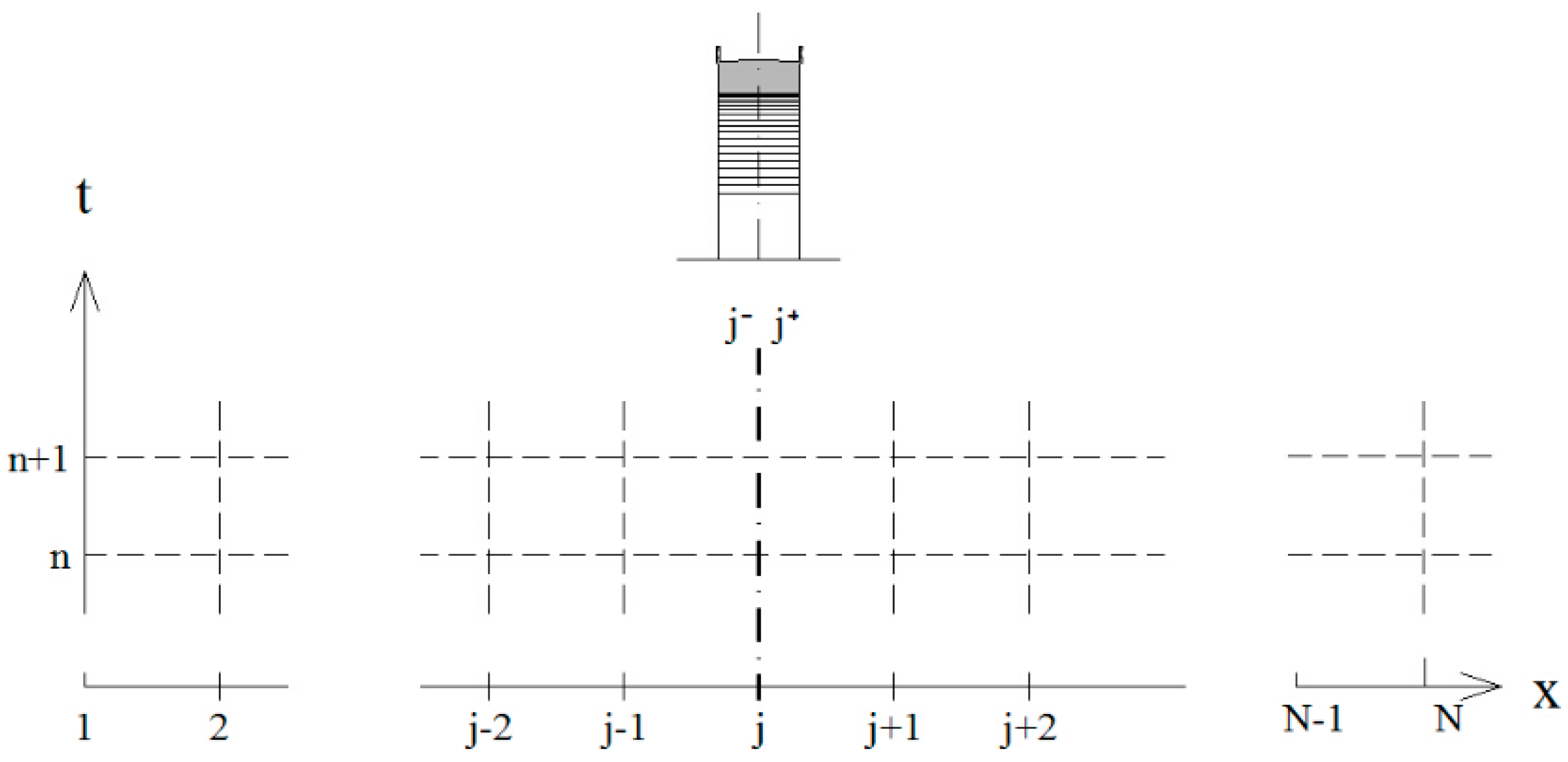
40]. Let us consider a generic structure (e.g., sluice-gate, sharp channel contraction, and bridge) located at the cross-section
j (
Figure 1), which represents the transversal axis of the structure, whose effective length is neglected. The upstream and downstream sides of the hydraulic structure are defined as cross-sections
j− and
j+. The cross-section
j also represents a disconnection between the upstream reach (from section 1 to
j−) and the downstream reach (from section
j+ to section
N).
The solution at cross-sections j − 1–j− and j+–j + 1 is evaluated by coupling the IBC model (at sections j+ or j−) with the mass balance equation solved with the Roe scheme.
In the following, the methodology description considers that the flow is moving from section 1 to section N. In the case of an opposite flow direction, the methodology direction must be reversed, too.
The proposed IBC model does not represent the actual shape of the bridge but uses a simplified rectangular opening obtained by considering the actual open span of the bridge and the position of its soffit and parapet.
2.1.1. Subcritical Flow
If the flow is in subcritical conditions, the hydraulic variables are evaluated at the upstream side of the bridge, cross-section
j+, by solving Equation (1) with the Roe scheme. The solution at
j− is then determined according to the IBC method by writing the mass balance at the two sides of the bridge (Equation (2)):
that is, neglecting the time variation of the water volume between the bridge’s sides and by applying the total energy balance through the singularity (Equation (3)):
The term
includes the minor losses due to the contraction and the expansion of the flow through the structure, evaluated implicitly, with the lateral contraction coefficient introduced as a function of the pier geometry, according to [
33].
2.1.2. Supercritical Flow
In the case of supercritical flow, the hydraulic variables at cross-section j− are computed by solving Equation (1) with the Roe scheme. The same procedure described for the Subcritical Flow is applied, that is, assigning the same discharge upstream and downstream of the bridge, (Equation (2)) and solving Equation (3). This time, however, the equations are employed to get the solution at the downstream side of the bridge, that is, at cross-section j+.
Once the hydraulic conditions at the bridge are determined, the downstream reach can be solved by applying Equation (1), noting that, if the flow energy is not sufficient to maintain supercritical flow conditions, critical flow is established at the bridge cross-section
j. In addition, if the flow is subcritical in cross-section
j + 1, a hydraulic jump can occur, and its position has to be determined. Defining as Σ the total momentum fluxes plus the total hydrostatic pressure [
41]:
the following conditions are considered to distinguish among the two above-described situations:
In Equation (4), besides the variables already introduced, ρ is the density of water, V is the velocity at the considered cross-section, computed with Equation (1), γ is the specific weight of water, and h is the water level.
2.1.3. Critical Flow Condition
Critical flow at the structure occurs if the flow energy at the upstream side (
j−) is insufficient for the flow to pass through the structure. The critical flow condition at cross-section
j (Equation (5)) is linked with the energy balance (Equation (6)), considering only the minor losses due to the contraction of the flow (Δ
HU):
Equation (5) is solved with Equation (6) to compute the hydraulic variables at the upstream side of the bridge. Once the hydraulic variables at
j− are computed, the solution at cross-section
j+ is evaluated in a direct way by imposing the discharge of cross-section
j− (Equation (7)) and by writing the energy balance between cross-sections
j+ and
j− considering the contraction and the expansion of the flow through the structure (Equation (8)):
The energy balance equation can also be written between cross-section j and cross-section j+, considering the expansion losses and evaluating the solution from downstream to upstream.
2.1.4. Pressure Flow
When the water level upstream of the bridge reaches the bridge’s low chord, at the downstream cross-section j+, the wetted area is imposed equal to the bridge span. The IBC is given by the energy equation applied between the upstream, j−, and the downstream, j+, cross-sections of the structure, including minor losses (Equation (8)).
The solution at the cross-section
j+ is obtained by following the procedure described in
Section 2.1.3 (Equations (7) and (8)).
In the case of submerged or drowned flow, a jet of water issuing from beneath the structure opening is assumed to be overlaid by a mass of water that has no net motion in any direction. The internal boundary condition can be expressed by the energy Equation (8), where the hydrostatic term is given by the subcritical solution at the
j + 1 cross-section and the inertial term is evaluated with the moving water depth (
), where
a =
bh is the bridge width (
b) multiplied by the water depth (
h) (see
Figure 2).
2.1.5. Overflow
An overtopped bridge can be considered a broad-crested or a sharp-crested weir depending on the ratio between the height of the water surface above the crest of the bridge,
Δ, and the length of the bridge,
l. If the ratio is in the range of 0.08 <
Δ/
l < 0.44, a broad-crested weir can be considered, while if
Δ/
l > 0.4, the bridge can be considered a sharp-crested weir. Bridges that are very long with respect to the overtopping water level (
Δ/
l < 0.08) can be considered as horizontal channels [
40].
The flow under the structure is computed as described for the pressure flow conditions, Equation (7), while the overflowing discharge (
) is evaluated using the classical weir formula [
42]:
where
μ is the weir coefficient and
bj−1 is the channel width upstream of the bridge.
The overflowing discharge is added in cross-section
j + 1 thanks to the source vector S (Equation (1)), by computing a lateral inflow,
qo, as follows:
where
is the distance between cross-section
j+ and cross-section
j + 1. In this way, the conservation of the discharge is assumed while the energy of the overflowing flow is dissipated. This assumption is not valid in cases of overflow with partially submerged hydraulic jumps or if the overflowing discharge leaves the domain.
2.2. Application of the 1D Internal Boundary Conditions Model
The proposed 1D unsteady IBC model is applied to an exhaustive laboratory campaign of dam break experiments carried out at the LIFTEC-CSIC laboratory of the University of Zaragoza [
25]. In the experimental campaign, water level measurements are carried out for a series of bridges with different designs in a rectangular horizontal flume, 6 m long, 0.24 m wide, and with vertical walls 0.16 m high. A pneumatic gate separates the flume from the upstream reservoir, whose bottom is 0.12 m lower than the bottom of the flume. The downstream end of the flume is closed. Continuous measurements of the water depth were recorded at the axis of the bridge and at the upstream and downstream cross-sections (
j− and
j+). These tests represent a complete set of flow conditions since free flow, pressure flow, and overflow occur at the bridge section.
Table 1 shows a summary of the simulated tests and of the initial conditions. In the Table,
B is the channel width,
b is the contraction width under the bridge,
l is the bridge length,
hreservoir is the water level in the upstream reservoir before the opening of the pneumatic gate, and
hdownstream is the initial water depth downstream of the gate. Test numbers and bridge types refer to the definition by [
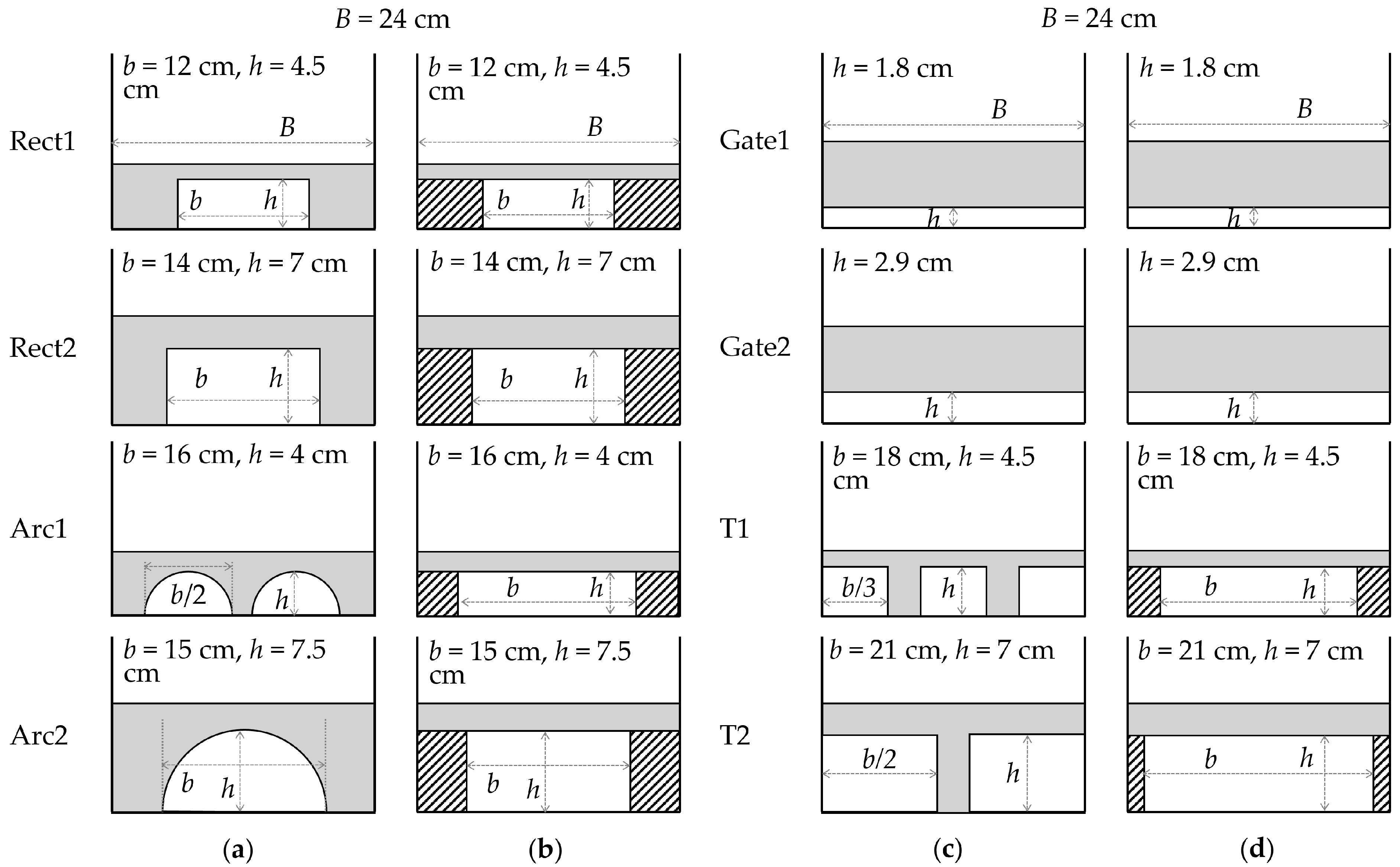
25]. Bridges Rect1 and Rect2 are standard bridges with two abutments; bridge T1 has two rectangular piers, while bridge T2 has a central rectangular pier. Bridge Arc1 has two circular openings and one pier, while Arc2 has one circular opening with two abutments. Gate1 and Gate2 are two gates without piers.
As the geometry implemented in the model is slightly simplified with respect to the actual geometry, a comparison of the two geometries is shown in
Figure 2.
Figure 2.
Frontal-view schemes of the modeled bridges. All four types of bridges are presented, with the geometry used in [
25] (
a,
c) and the simplified geometry for the 1D IBC model (
b,
d).
B,
b, and
h are the flume width, the contraction width, and the maximum vertical span, respectively.
Figure 2.
Frontal-view schemes of the modeled bridges. All four types of bridges are presented, with the geometry used in [
25] (
a,
c) and the simplified geometry for the 1D IBC model (
b,
d).
B,
b, and
h are the flume width, the contraction width, and the maximum vertical span, respectively.
3. Results
All 16 tests in
Table 1 were simulated, both with the standard 1D model (Equation (1), with
α = 1) and with the proposed 1D IBC model. The 1D geometry was described by cross-section spacing of 0.1 m. Close to the bridge, the spatial discretization step was reduced to better represent the bridge cross-sections since, in most tests, the length of the bridge is 0.06 m. A solid wall condition was imposed at the downstream end. Since no data of the discharge hydrograph entering the channel were available, the reservoir and the sudden release of the water in the flume were simulated in the 1D model. The Manning coefficient used to represent the flume roughness was 0.011 m s
−1/3, as indicated by the authors of the experiments.
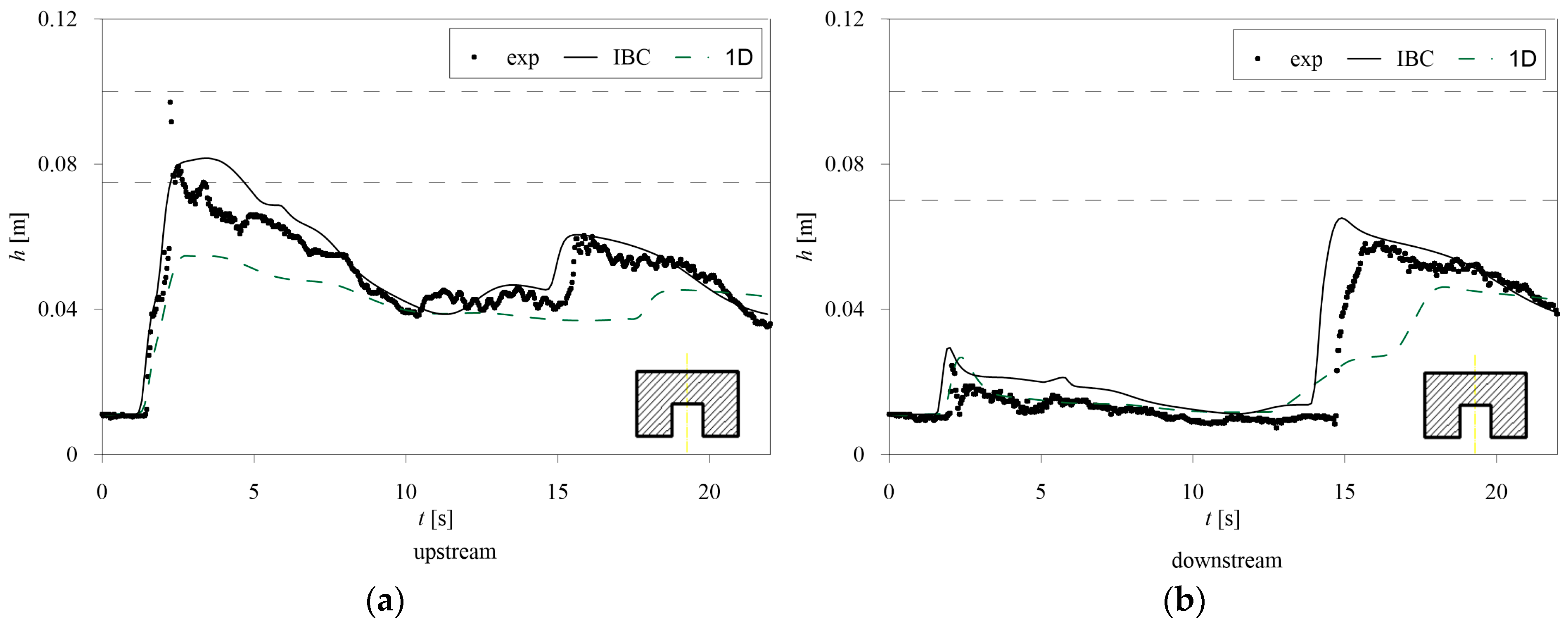
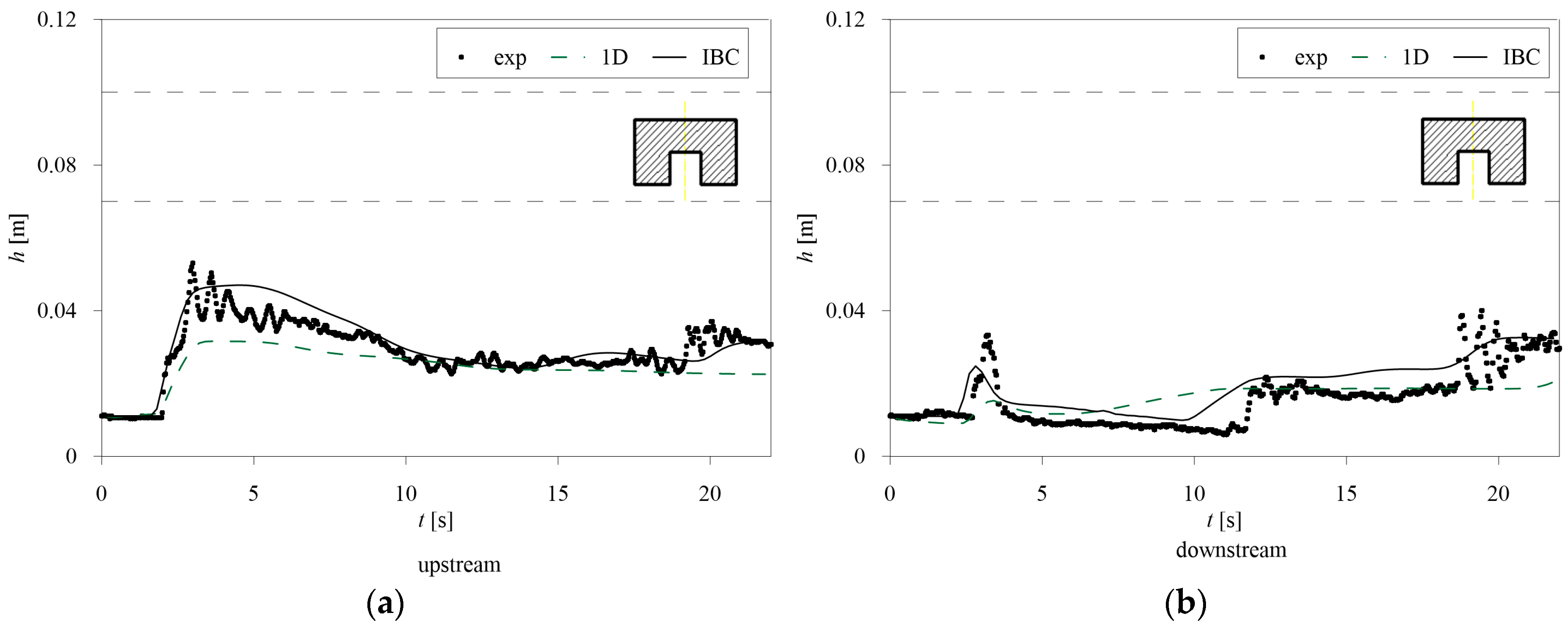
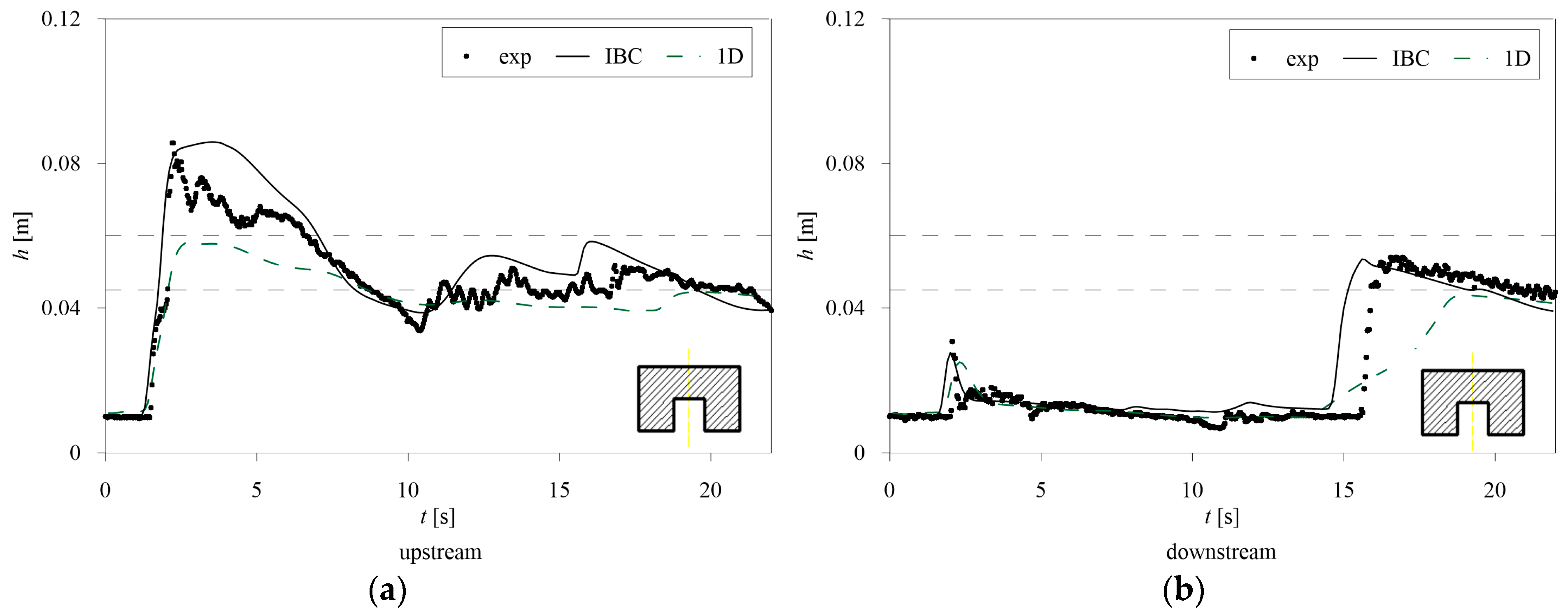
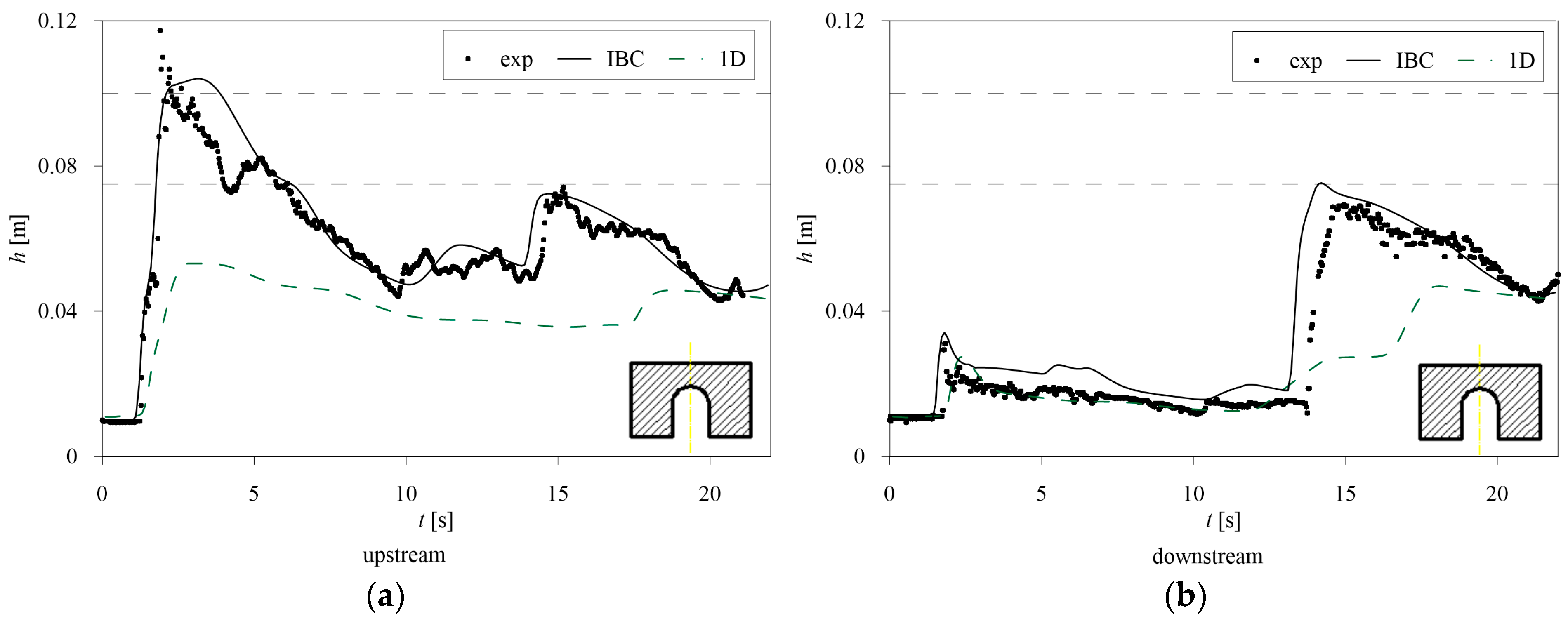
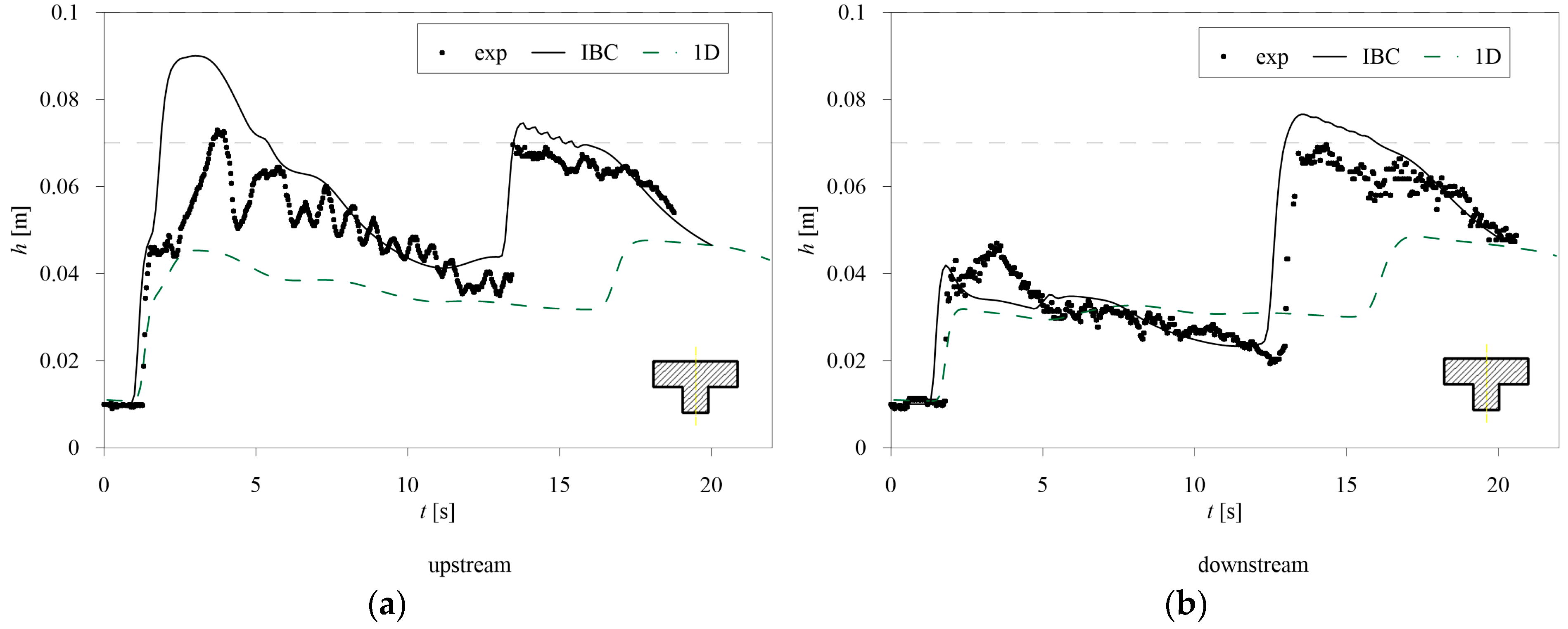
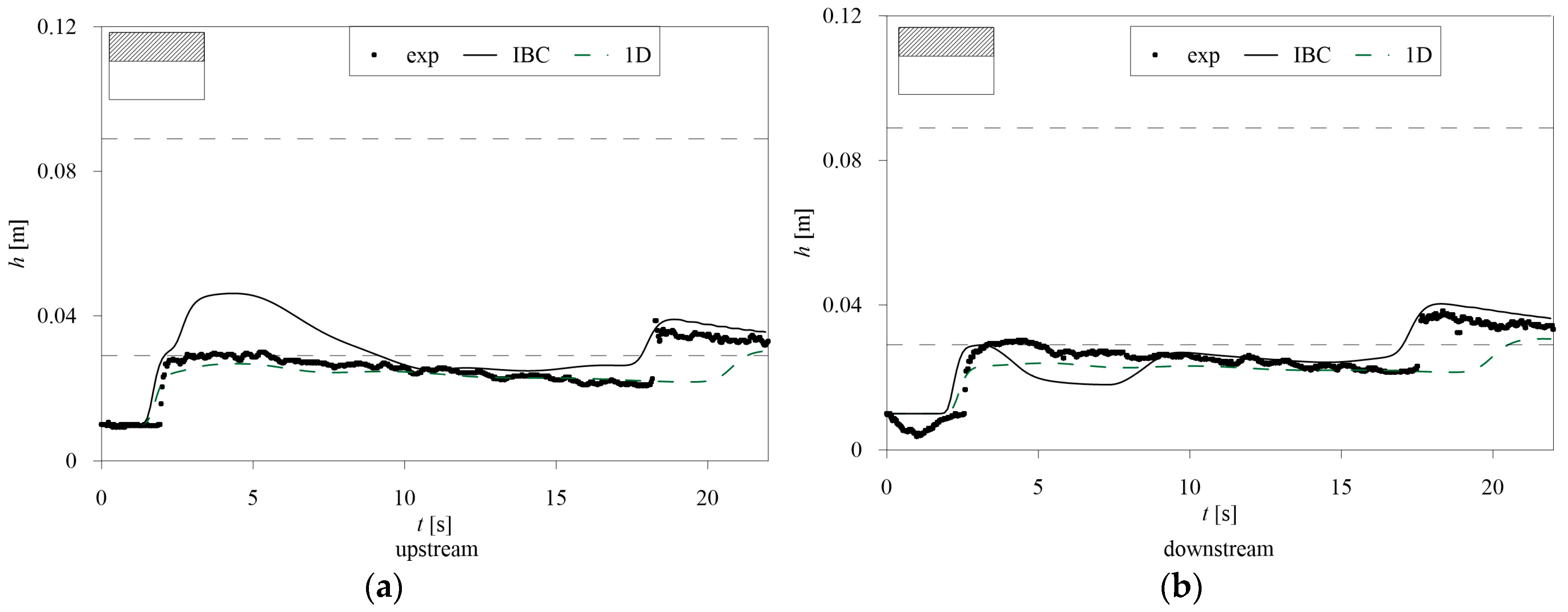
The comparison between the simulated water depths upstream and downstream of the bridge and the experimental data is shown for 6 selected tests, representative of all the bridges and all the flow conditions. The results for the other tests are available in the
Supplementary Material. The horizontal dashed lines indicate the bridge’s low chord and parapet. For arch bridges, the maximum elevation of the bridge’s low chord is considered, as shown in
Figure 2.
The numerical results include the 1D unsteady flow model with the IBC, indicated with a continuous line, and the 1D unsteady flow model where only energy losses are added (Equation (1), with parameter α equal to 1), indicated with a dashed line.
Figure 3,
Figure 4,
Figure 5,
Figure 6,
Figure 7 and
Figure 8 show that the Internal Boundary Conditions (IBCs) model can represent the different types of flow obtained during the experimental campaign (Free Surface Flow, Pressure Flow, or Overflow).
Among the presented tests, Free Surface Flow occurs in P3 and P15, Pressure Flow occurs in P2 and P12, and Overflow occurs in P4 and P10.
Even in the case of Free Surface Flow (
Figure 4 and
Figure 8), only the 1D IBC model can properly represent the measured phenomenon. The 1D unsteady model with energy losses (Equation (1), with
α = 1, named 1D in the figures) fails in replicating the maximum water levels and the effects of the reflection waves, especially in the downstream cross-sections, probably due to the lack of the flow contraction through the bridge.
Focusing on the Pressure Flow tests (
Figure 3 and
Figure 7), the higher capability of the 1D IBC model in catching both the water elevations and the timing of the waves is evident. The 1D model does not represent the blockage of the bridge opening, simulating free flow conditions for both test cases, independently of the bridge type. As a result, the water level is underestimated, especially at the upstream cross-sections. In addition, also in this case, poor capability in replicating the reflection waves is shown. Overflow occurs for both P4 and P10 tests (
Figure 5 and
Figure 6). The IBC model can represent the backwater effect given by both types of bridges, slightly overestimating the maximum water level for T2 bridge type (
Figure 7). The model can also replicate the reflection of the wave against the downstream end, even if it is slightly anticipated, especially in the downstream cross-section. The 1D classical model, where only energy losses are added, underestimates the upstream water depth and the downstream hydraulic jump.
Figure 7 and
Figure 8 show an overestimation of the maximum water level by the IBC model in the upstream cross-section, while for the downstream one, both the main peak and the reflection wave are well simulated.
Even if the correct shape of the bridge opening is not represented by the 1D IBC model, since only an equivalent narrowing width is considered, it can represent the upstream and downstream water depth hydrographs in a satisfactory way.
In all the tests, the 1D IBC model accurately simulates the arrival time of the front and can reproduce the first reflection of the shock wave, even if it is slightly anticipated in the downstream cross-section. Both the 1D IBC and the 1D models fail to reproduce the large number of small oscillations of the experimental data, the former model being generally more consistent with the measurements than the latter in the upstream and downstream cross-sections.
Many metrics can be used to quantify the error in replicating measured water elevations [
43]. The RMSE (Root Mean Square Error) was calculated for all the tests for both models, and it was also divided by the maximum experimental water depth for each test to evaluate a relative value.
Table 2 and
Table 3 show the RMSE and the relative RMSE for all the tests with the 1D IBC model and 1D model, respectively, for the upstream and downstream cross-sections.
For the 1D IBC model, the minimum RMSE for the upstream cross-section was 0.004 m (P3), corresponding to a relative RMSE of 6%. For the downstream cross-section, the minimum is slightly higher, that is 0.005 m (for tests P3, P9, P14, and P15). The minimum relative value is around 8% (for test P15), while the maximum value was 19% for the upstream and 20% for the downstream cross-section (for tests P15 and P11, respectively). The average relative RMSE is slightly higher for the downstream cross-section, being less than 15% for both locations.
For the standard 1D model, higher values are observed. The average relative RMSE is 17% and 21% for the upstream and downstream cross-sections, reaching maximum values of about 34% (for test P7, upstream, and test P18, downstream). These metrics confirm that the 1D IBC model can better simulate the backwater dynamics than the standard one, providing RMSE values that are more than acceptable in real-world applications.
The relative RMSE is then computed considering groups of tests with the same type of flow or the same type of bridge.
Figure 9a shows that the relative RMSE for the 1D IBC model is similar for the three types of flow observed in the experiments, with the Overflow tests presenting an overall average slightly lower than the other two flow types for the upstream and downstream cross-sections. For the standard 1D model, Pressure Flow presents the highest values of the relative RMSE, while Free Surface Flow tests present an accuracy near the one of the IBC model. For the 1D IBC model, if the average percentage RMSE is computed according to the bridge type (
Figure 9b), the Arch ones present smaller errors in the upstream cross-section and the largest differences between the upstream and the downstream values. For the same model, Gates and T-shaped bridges have similar accuracy upstream and downstream of the structure. The results are different for the standard 1D model, which presents the largest difference between upstream and downstream for Rectangular and Gate types, while Arch and T-shaped bridge types have similar errors, although larger than the 1D IBC model.
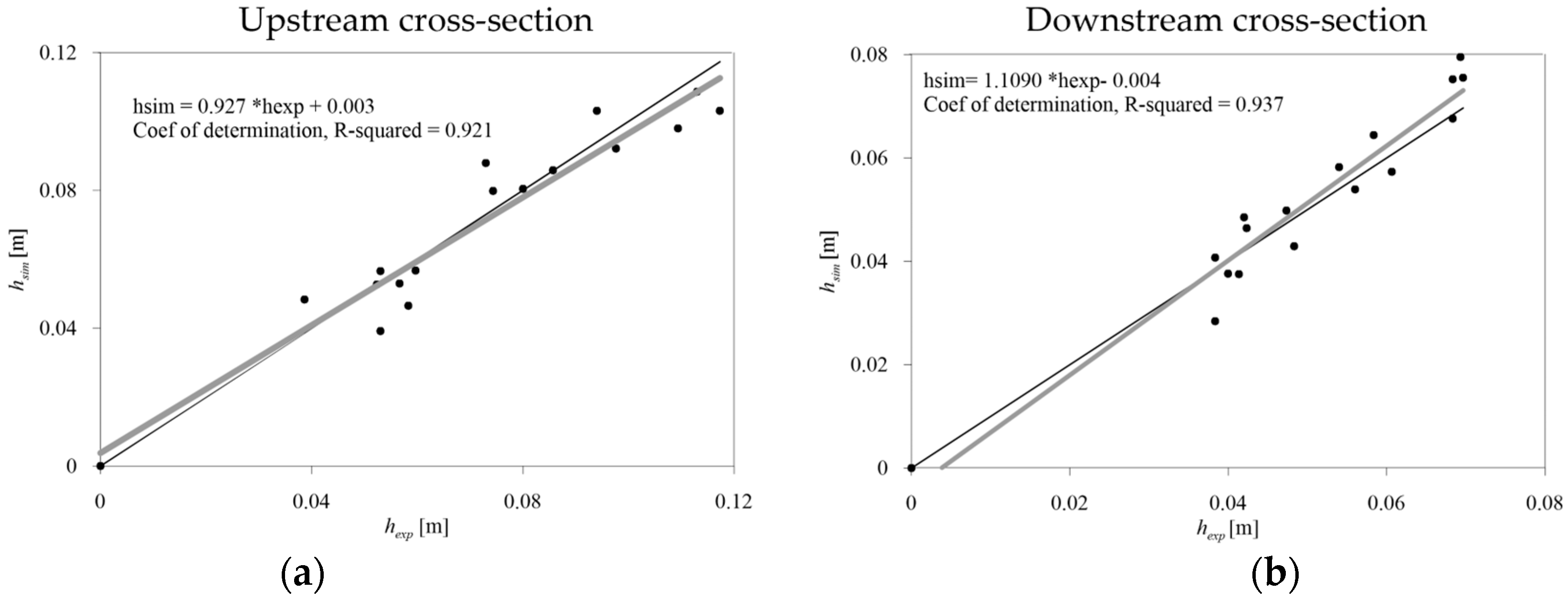
Figure 10 shows the comparison between experimental and simulated maximum water depths. The black line refers to the perfect agreement. Adequate agreement is found for the IBC model, both in the upstream and in the downstream cross-section, since the angular coefficient of the regression curve is very close to 1, and the determination coefficient R
2 is higher than 0.9 in both cases.
On the contrary,
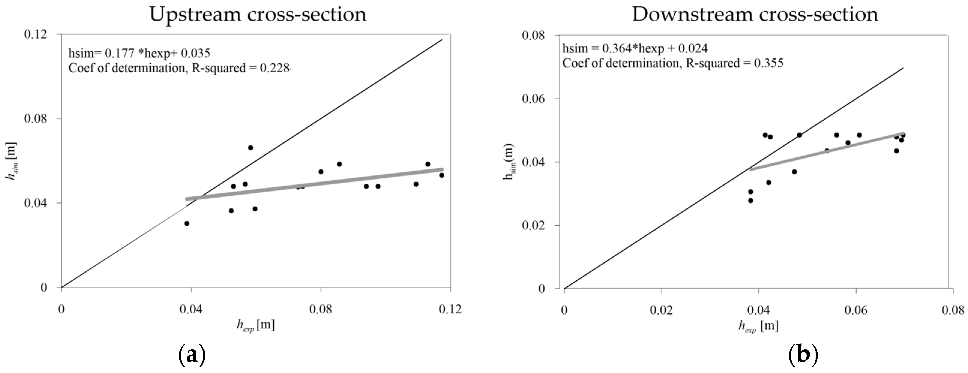
Figure 11 shows a significant underestimation of the maximum water level, especially in the upstream cross-section for the standard 1D model (Equation (1)), highlighted by the low angular coefficient of the regression curves and determination coefficient.
The PBIAS was also estimated to evaluate the differences between the observed values and the simulated ones, following the suggestions by [
44] (
Table 4). No tests fall in the Unsatisfactory rating (PBIAS > 25%) for the 1D IBC model, while 43% and 31% of the tests simulated with the 1D standard model fall in that class for the upstream and downstream cross-sections, respectively.
The 1D IBC model performs better than the standard one in both cross-sections, with nearly 69% and 75% of the simulated results presenting a PBIAS < 15% (Good and Very Good rating), upstream and downstream, respectively. Both models display a larger percentage of tests in high-rating classes for the downstream cross-sections. This highlights that some difficulties in replicating the backwater effects are present also in the 1D IBC model but are limited compared to the standard 1D model with head losses.
4. Conclusions
Unsteady flow simulation through hydraulic structures was investigated. Two 1D models are compared to simulate the flow through a bridge in unsteady conditions. One is the conservative form of the DSVE, including minor losses, while the second one is the conservative DSVE coupled with an IBC model that accounts for minor losses within the energy balance. In the latter model, flow through bridges is modeled by computing the mass balance and the energy balance with minor losses for different flow conditions (subcritical, supercritical, critical, pressure flow, and overflow). An equivalent narrowing of the structure is considered in both models. Thanks to the implemented equations, the 1D IBC model turns out to be the more flexible model since it can represent all the phenomena occurring in the flow field. The 1D unsteady model with energy losses, including the cross-section narrowing but without the complete bridge geometry, cannot simulate flow contraction at the bridge, underestimating the afflux level at the bridge location and overestimating the flow downstream of the bridge.
The proposed 1D IBC model can represent all the regimes since each flow condition can be easily modeled. In addition, only span width and elevation are needed for the computation, making the application of the model easier than standard 1D models, which require the implementation of the entire structure’s geometry. No sensitivity analysis has to be performed to calibrate the discharge coefficients in cases of pressure flow and overflow. The computation of error metrics showed that the model can replicate measured water levels with adequate accuracy, both in the upstream and downstream cross-sections.
Thanks to the application to a complete set of experimental data, the IBC model proved to represent the backwater effect in a very satisfactory way.
